WO2016190275A1 - クラッチ - Google Patents
クラッチ Download PDFInfo
- Publication number
- WO2016190275A1 WO2016190275A1 PCT/JP2016/065149 JP2016065149W WO2016190275A1 WO 2016190275 A1 WO2016190275 A1 WO 2016190275A1 JP 2016065149 W JP2016065149 W JP 2016065149W WO 2016190275 A1 WO2016190275 A1 WO 2016190275A1
- Authority
- WO
- WIPO (PCT)
- Prior art keywords
- armature
- rotor
- base material
- contact surface
- clutch
- Prior art date
- Legal status (The legal status is an assumption and is not a legal conclusion. Google has not performed a legal analysis and makes no representation as to the accuracy of the status listed.)
- Ceased
Links
Images



Classifications
-
- F—MECHANICAL ENGINEERING; LIGHTING; HEATING; WEAPONS; BLASTING
- F16—ENGINEERING ELEMENTS AND UNITS; GENERAL MEASURES FOR PRODUCING AND MAINTAINING EFFECTIVE FUNCTIONING OF MACHINES OR INSTALLATIONS; THERMAL INSULATION IN GENERAL
- F16D—COUPLINGS FOR TRANSMITTING ROTATION; CLUTCHES; BRAKES
- F16D27/00—Magnetically- or electrically- actuated clutches; Control or electric circuits therefor
- F16D27/10—Magnetically- or electrically- actuated clutches; Control or electric circuits therefor with an electromagnet not rotating with a clutching member, i.e. without collecting rings
- F16D27/108—Magnetically- or electrically- actuated clutches; Control or electric circuits therefor with an electromagnet not rotating with a clutching member, i.e. without collecting rings with axially movable clutching members
- F16D27/112—Magnetically- or electrically- actuated clutches; Control or electric circuits therefor with an electromagnet not rotating with a clutching member, i.e. without collecting rings with axially movable clutching members with flat friction surfaces, e.g. discs
-
- C—CHEMISTRY; METALLURGY
- C23—COATING METALLIC MATERIAL; COATING MATERIAL WITH METALLIC MATERIAL; CHEMICAL SURFACE TREATMENT; DIFFUSION TREATMENT OF METALLIC MATERIAL; COATING BY VACUUM EVAPORATION, BY SPUTTERING, BY ION IMPLANTATION OR BY CHEMICAL VAPOUR DEPOSITION, IN GENERAL; INHIBITING CORROSION OF METALLIC MATERIAL OR INCRUSTATION IN GENERAL
- C23C—COATING METALLIC MATERIAL; COATING MATERIAL WITH METALLIC MATERIAL; SURFACE TREATMENT OF METALLIC MATERIAL BY DIFFUSION INTO THE SURFACE, BY CHEMICAL CONVERSION OR SUBSTITUTION; COATING BY VACUUM EVAPORATION, BY SPUTTERING, BY ION IMPLANTATION OR BY CHEMICAL VAPOUR DEPOSITION, IN GENERAL
- C23C10/00—Solid state diffusion of only metal elements or silicon into metallic material surfaces
- C23C10/06—Solid state diffusion of only metal elements or silicon into metallic material surfaces using gases
- C23C10/14—Solid state diffusion of only metal elements or silicon into metallic material surfaces using gases more than one element being diffused in one step
-
- C—CHEMISTRY; METALLURGY
- C23—COATING METALLIC MATERIAL; COATING MATERIAL WITH METALLIC MATERIAL; CHEMICAL SURFACE TREATMENT; DIFFUSION TREATMENT OF METALLIC MATERIAL; COATING BY VACUUM EVAPORATION, BY SPUTTERING, BY ION IMPLANTATION OR BY CHEMICAL VAPOUR DEPOSITION, IN GENERAL; INHIBITING CORROSION OF METALLIC MATERIAL OR INCRUSTATION IN GENERAL
- C23C—COATING METALLIC MATERIAL; COATING MATERIAL WITH METALLIC MATERIAL; SURFACE TREATMENT OF METALLIC MATERIAL BY DIFFUSION INTO THE SURFACE, BY CHEMICAL CONVERSION OR SUBSTITUTION; COATING BY VACUUM EVAPORATION, BY SPUTTERING, BY ION IMPLANTATION OR BY CHEMICAL VAPOUR DEPOSITION, IN GENERAL
- C23C10/00—Solid state diffusion of only metal elements or silicon into metallic material surfaces
- C23C10/18—Solid state diffusion of only metal elements or silicon into metallic material surfaces using liquids, e.g. salt baths, liquid suspensions
- C23C10/20—Solid state diffusion of only metal elements or silicon into metallic material surfaces using liquids, e.g. salt baths, liquid suspensions only one element being diffused
- C23C10/24—Salt bath containing the element to be diffused
-
- C—CHEMISTRY; METALLURGY
- C23—COATING METALLIC MATERIAL; COATING MATERIAL WITH METALLIC MATERIAL; CHEMICAL SURFACE TREATMENT; DIFFUSION TREATMENT OF METALLIC MATERIAL; COATING BY VACUUM EVAPORATION, BY SPUTTERING, BY ION IMPLANTATION OR BY CHEMICAL VAPOUR DEPOSITION, IN GENERAL; INHIBITING CORROSION OF METALLIC MATERIAL OR INCRUSTATION IN GENERAL
- C23C—COATING METALLIC MATERIAL; COATING MATERIAL WITH METALLIC MATERIAL; SURFACE TREATMENT OF METALLIC MATERIAL BY DIFFUSION INTO THE SURFACE, BY CHEMICAL CONVERSION OR SUBSTITUTION; COATING BY VACUUM EVAPORATION, BY SPUTTERING, BY ION IMPLANTATION OR BY CHEMICAL VAPOUR DEPOSITION, IN GENERAL
- C23C10/00—Solid state diffusion of only metal elements or silicon into metallic material surfaces
- C23C10/60—After-treatment
-
- C—CHEMISTRY; METALLURGY
- C23—COATING METALLIC MATERIAL; COATING MATERIAL WITH METALLIC MATERIAL; CHEMICAL SURFACE TREATMENT; DIFFUSION TREATMENT OF METALLIC MATERIAL; COATING BY VACUUM EVAPORATION, BY SPUTTERING, BY ION IMPLANTATION OR BY CHEMICAL VAPOUR DEPOSITION, IN GENERAL; INHIBITING CORROSION OF METALLIC MATERIAL OR INCRUSTATION IN GENERAL
- C23C—COATING METALLIC MATERIAL; COATING MATERIAL WITH METALLIC MATERIAL; SURFACE TREATMENT OF METALLIC MATERIAL BY DIFFUSION INTO THE SURFACE, BY CHEMICAL CONVERSION OR SUBSTITUTION; COATING BY VACUUM EVAPORATION, BY SPUTTERING, BY ION IMPLANTATION OR BY CHEMICAL VAPOUR DEPOSITION, IN GENERAL
- C23C8/00—Solid state diffusion of only non-metal elements into metallic material surfaces; Chemical surface treatment of metallic material by reaction of the surface with a reactive gas, leaving reaction products of surface material in the coating, e.g. conversion coatings, passivation of metals
- C23C8/06—Solid state diffusion of only non-metal elements into metallic material surfaces; Chemical surface treatment of metallic material by reaction of the surface with a reactive gas, leaving reaction products of surface material in the coating, e.g. conversion coatings, passivation of metals using gases
- C23C8/28—Solid state diffusion of only non-metal elements into metallic material surfaces; Chemical surface treatment of metallic material by reaction of the surface with a reactive gas, leaving reaction products of surface material in the coating, e.g. conversion coatings, passivation of metals using gases more than one element being applied in one step
- C23C8/30—Carbo-nitriding
-
- F—MECHANICAL ENGINEERING; LIGHTING; HEATING; WEAPONS; BLASTING
- F16—ENGINEERING ELEMENTS AND UNITS; GENERAL MEASURES FOR PRODUCING AND MAINTAINING EFFECTIVE FUNCTIONING OF MACHINES OR INSTALLATIONS; THERMAL INSULATION IN GENERAL
- F16D—COUPLINGS FOR TRANSMITTING ROTATION; CLUTCHES; BRAKES
- F16D13/00—Friction clutches
- F16D13/58—Details
- F16D13/60—Clutching elements
- F16D13/64—Clutch-plates; Clutch-lamellae
-
- F—MECHANICAL ENGINEERING; LIGHTING; HEATING; WEAPONS; BLASTING
- F16—ENGINEERING ELEMENTS AND UNITS; GENERAL MEASURES FOR PRODUCING AND MAINTAINING EFFECTIVE FUNCTIONING OF MACHINES OR INSTALLATIONS; THERMAL INSULATION IN GENERAL
- F16D—COUPLINGS FOR TRANSMITTING ROTATION; CLUTCHES; BRAKES
- F16D13/00—Friction clutches
- F16D13/76—Friction clutches specially adapted to incorporate with other transmission parts, i.e. at least one of the clutch parts also having another function, e.g. being the disc of a pulley
-
- F—MECHANICAL ENGINEERING; LIGHTING; HEATING; WEAPONS; BLASTING
- F16—ENGINEERING ELEMENTS AND UNITS; GENERAL MEASURES FOR PRODUCING AND MAINTAINING EFFECTIVE FUNCTIONING OF MACHINES OR INSTALLATIONS; THERMAL INSULATION IN GENERAL
- F16D—COUPLINGS FOR TRANSMITTING ROTATION; CLUTCHES; BRAKES
- F16D3/00—Yielding couplings, i.e. with means permitting movement between the connected parts during the drive
- F16D3/50—Yielding couplings, i.e. with means permitting movement between the connected parts during the drive with the coupling parts connected by one or more intermediate members
- F16D3/76—Yielding couplings, i.e. with means permitting movement between the connected parts during the drive with the coupling parts connected by one or more intermediate members shaped as an elastic ring centered on the axis, surrounding a portion of one coupling part and surrounded by a sleeve of the other coupling part
-
- F—MECHANICAL ENGINEERING; LIGHTING; HEATING; WEAPONS; BLASTING
- F16—ENGINEERING ELEMENTS AND UNITS; GENERAL MEASURES FOR PRODUCING AND MAINTAINING EFFECTIVE FUNCTIONING OF MACHINES OR INSTALLATIONS; THERMAL INSULATION IN GENERAL
- F16D—COUPLINGS FOR TRANSMITTING ROTATION; CLUTCHES; BRAKES
- F16D13/00—Friction clutches
- F16D13/22—Friction clutches with axially-movable clutching members
- F16D13/38—Friction clutches with axially-movable clutching members with flat clutching surfaces, e.g. discs
- F16D13/40—Friction clutches with axially-movable clutching members with flat clutching surfaces, e.g. discs in which the or each axially-movable member is pressed exclusively against an axially-located member
-
- F—MECHANICAL ENGINEERING; LIGHTING; HEATING; WEAPONS; BLASTING
- F16—ENGINEERING ELEMENTS AND UNITS; GENERAL MEASURES FOR PRODUCING AND MAINTAINING EFFECTIVE FUNCTIONING OF MACHINES OR INSTALLATIONS; THERMAL INSULATION IN GENERAL
- F16D—COUPLINGS FOR TRANSMITTING ROTATION; CLUTCHES; BRAKES
- F16D2200/00—Materials; Production methods therefor
- F16D2200/0004—Materials; Production methods therefor metallic
- F16D2200/0008—Ferro
- F16D2200/0021—Steel
-
- F—MECHANICAL ENGINEERING; LIGHTING; HEATING; WEAPONS; BLASTING
- F16—ENGINEERING ELEMENTS AND UNITS; GENERAL MEASURES FOR PRODUCING AND MAINTAINING EFFECTIVE FUNCTIONING OF MACHINES OR INSTALLATIONS; THERMAL INSULATION IN GENERAL
- F16D—COUPLINGS FOR TRANSMITTING ROTATION; CLUTCHES; BRAKES
- F16D2200/00—Materials; Production methods therefor
- F16D2200/0034—Materials; Production methods therefor non-metallic
- F16D2200/0052—Carbon
-
- F—MECHANICAL ENGINEERING; LIGHTING; HEATING; WEAPONS; BLASTING
- F16—ENGINEERING ELEMENTS AND UNITS; GENERAL MEASURES FOR PRODUCING AND MAINTAINING EFFECTIVE FUNCTIONING OF MACHINES OR INSTALLATIONS; THERMAL INSULATION IN GENERAL
- F16D—COUPLINGS FOR TRANSMITTING ROTATION; CLUTCHES; BRAKES
- F16D2250/00—Manufacturing; Assembly
- F16D2250/0038—Surface treatment
- F16D2250/0046—Coating
-
- F—MECHANICAL ENGINEERING; LIGHTING; HEATING; WEAPONS; BLASTING
- F16—ENGINEERING ELEMENTS AND UNITS; GENERAL MEASURES FOR PRODUCING AND MAINTAINING EFFECTIVE FUNCTIONING OF MACHINES OR INSTALLATIONS; THERMAL INSULATION IN GENERAL
- F16H—GEARING
- F16H55/00—Elements with teeth or friction surfaces for conveying motion; Worms, pulleys or sheaves for gearing mechanisms
- F16H55/32—Friction members
- F16H55/36—Pulleys
Definitions
- This disclosure relates to clutches.
- the friction surface in the initial state in which the friction surface of the armature and the friction surface of the rotor have just been formed by cutting or polishing, has a relatively small friction coefficient, and therefore has a small transmission torque.
- both friction surfaces are oxidized to increase the friction coefficient and increase the transmission torque (see, for example, Patent Document 1).
- the torque transmission is actually repeatedly interrupted to oxidize the friction surface and increase the transmission torque of the electromagnetic clutch.
- the running-in operation is not performed before the product is shipped, and the effect of the running-in is obtained while being used in the market after the product is shipped.
- the break-in operation time becomes long in the clutch manufacturing process, and the time required for the clutch manufacture becomes long. Also, when shipping a product without running-in, it takes a long time for the transmission torque to rise and a high transmission torque to be stably obtained from the start of use of the product. End up.
- This disclosure aims to provide a clutch capable of increasing the transmission torque in a short time and obtaining a stable high transmission torque.
- the clutch is A rotor that uses a steel material as a base material and rotates by receiving a rotational driving force from a driving source; With a steel material as a base material, it is equipped with an armature to which rotational driving force is transmitted by being attracted to the rotor by magnetic force,
- the armature has a contact surface side region including a contact surface that comes into contact with the counterpart when the armature is attracted to the rotor,
- the contact surface side region has a plurality of holes opened at the contact surface, and a nitriding compound of an element in the base material is generated by a nitriding reaction of a part of the base material. Harder than the part.
- the clutch is A rotor that uses a steel material as a base material and rotates by receiving a rotational driving force from a driving source; With a steel material as a base material, it is equipped with an armature to which rotational driving force is transmitted by being attracted to the rotor by magnetic force,
- the armature has a contact surface side region including a contact surface that comes into contact with the counterpart when the armature is attracted to the rotor,
- the contact surface side region has a plurality of holes opened at the contact surface, and a nitride compound of an element in the base material is generated, and is harder than the base material.
- the clutch is A rotor that uses a steel material as a base material and rotates by receiving a rotational driving force from a driving source; With a steel material as a base material, it is equipped with an armature to which rotational driving force is transmitted by being attracted to the rotor by magnetic force,
- the rotor has a contact surface side region including a contact surface that comes into contact with the counterpart when the armature is attracted to the rotor,
- the contact surface side region has a plurality of holes opened at the contact surface, and a nitriding compound of an element in the base material is generated by a nitriding reaction of a part of the base material. Harder than the part.
- the clutch is A rotor that uses a steel material as a base material and rotates by receiving a rotational driving force from a driving source; With a steel material as a base material, it is equipped with an armature to which rotational driving force is transmitted by being attracted to the rotor by magnetic force,
- the rotor has a contact surface side region including a contact surface that comes into contact with the counterpart when the armature is attracted to the rotor,
- the contact surface side region has a plurality of holes opened at the contact surface, and a nitride compound of an element in the base material is generated, and is harder than the base material.
- the contact surface side region is worn by repeating the attachment / detachment of the armature and the rotor (that is, transmission and interruption of torque) to generate hard wear powder, and the generated wear powder is generated in the contact surface side region. Retained inside the hole. For this reason, the true contact area between the armature and the rotor at the time of adsorption (that is, when torque is transmitted) is improved, and hard wear powder is interposed between the contact surface of the armature and the contact surface of the rotor, so that the friction resistance Will improve. Therefore, according to the clutch of the present disclosure, in a short time from the start of torque transmission and interruption, the transmission torque is increased compared to the transmission torque when both contact surfaces are in the initial state, and a stable high transmission torque is obtained. be able to.
- the contact surface side region in the clutch of the present disclosure is a region in which a nitride compound of an element in the base material is generated by a nitriding reaction of a part of the base material, and is a part of the armature or the rotor. For this reason, unlike the clutch of this indication, a number of parts can be reduced compared with the case where the member equivalent to a contact surface side field is joined to a contact surface.
- a steel material is used as a base material, a rotor that rotates by receiving a rotational driving force from a drive source, and a steel material is used as a base material, and is attracted to the rotor by a magnetic force.
- a manufacturing method of a clutch including an armature to which a rotational driving force is transmitted is as follows: A machining step of forming an armature having a contact surface that comes into contact with the counterpart when the armature is adsorbed to the rotor by machining the base material; A soft nitriding step of forming a contact surface side region that has a plurality of holes that are open at the contact surface and is harder than the base material by performing soft nitriding treatment on at least the contact surface of the armature after the processing step When, After the soft nitriding step, a rust-preventing step of forming a rust-preventing film by applying a rust-preventing treatment to a region excluding at least the contact surface of the surface of the armature is provided.
- the contact surface side region formed by soft nitriding is a layer harder than an unreacted portion of the nitriding reaction in the base material, while a nitride compound of the element in the base material is generated. Therefore, according to this clutch manufacturing method, the clutch of the present disclosure can be manufactured.
- the heating temperature in soft nitriding is 550 to 600 ° C.
- the rust preventive film formed by a general rust preventive treatment is lost or deteriorated at the heating temperature of the soft nitriding treatment. For this reason, if the soft nitriding step is performed after the rust prevention step, the rust prevention film disappears or deteriorates, and the high corrosion resistance of the clutch cannot be ensured.
- the processing step includes a finishing step of forming a contact surface of the armature by cutting the surface of the base material press-molded into the shape of the armature.
- the finishing process is performed after the soft nitriding process, the porous contact surface side region formed in the soft nitriding process is scraped and disappears. Therefore, by performing the soft nitriding step after the processing step having the finishing step, it is possible to avoid the loss of the porous contact surface side region due to the finishing step.
- this clutch manufacturing method it is possible to manufacture a clutch in which a porous contact surface side region is formed on the contact surface of the armature and a rust preventive film is formed on the surface of the region excluding the contact surface of the armature. it can.
- a steel material is used as a base material, a rotor that rotates by receiving a rotational driving force from a drive source, and a steel material is used as a base material, and is attracted to the rotor by a magnetic force.
- a manufacturing method of a clutch including an armature to which a rotational driving force is transmitted is as follows: A machining process for forming a rotor having a contact surface that comes into contact with the counterpart when the armature is adsorbed to the rotor by machining the base material; A soft nitriding step of forming a contact surface side region that has a plurality of holes opened in the contact surface and is harder than the base material by performing soft nitriding treatment on at least the contact surface of the rotor after the processing step When, After the soft nitriding step, a rust-preventing step of forming a rust-preventing film by performing a rust-proofing process on a region of the rotor surface excluding at least the contact surface is provided.
- the contact surface side region formed by soft nitriding is a layer harder than an unreacted portion of the nitriding reaction in the base material, while a nitride compound of the element in the base material is generated. Therefore, according to this clutch manufacturing method, the clutch of the present disclosure can be manufactured.
- the heating temperature in soft nitriding is 550 to 600 ° C.
- the rust preventive film formed by a general rust preventive treatment is lost or deteriorated at the heating temperature of the soft nitriding treatment. For this reason, if the soft nitriding step is performed after the rust prevention step, the rust prevention film disappears or deteriorates, and the high corrosion resistance of the clutch cannot be ensured.
- the processing step includes a finishing step of forming the contact surface of the rotor by cutting the surface of the base material press-molded into the shape of the rotor.
- the finishing process is performed after the soft nitriding process, the porous contact surface side region formed in the soft nitriding process is scraped and disappears. Therefore, by performing the soft nitriding step after the processing step having the finishing step, it is possible to avoid the loss of the porous contact surface side region due to the finishing step.
- this clutch manufacturing method it is possible to manufacture a clutch in which a porous contact surface side region is formed on the contact surface of the rotor and a rust preventive film is formed on the surface of the region excluding the contact surface of the rotor. it can.
- FIG. 3 is an enlarged view of a white layer and a compound layer in FIG. 2.
- FIG. 3 is an enlarged view of a white layer and a compound layer in FIG. 2.
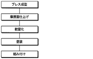
- FIG. 3 shows the manufacturing process of the armature in 1st Embodiment.
- FIG. 2 shows the manufacturing process of the armature in 1st Embodiment.
- FIG. 3 shows the manufacturing process of the armature in 1st Embodiment.
- FIG. 2 is an expanded sectional view of the friction surface of the armature when the clutch is used.
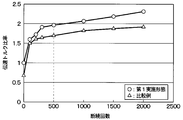
- FIG. It is a figure which shows the evaluation result of the transmission torque of the electromagnetic clutch of this embodiment, and the electromagnetic clutch of the comparative example 1.
- FIG. It is a figure which shows the manufacturing process of the armature in the comparative example 1.
- An electromagnetic clutch 1 according to the first embodiment shown in FIG. 1 is used for a drive mechanism of a compressor 2 that obtains a rotational drive force from an engine as a drive source that outputs a vehicle travel drive force and rotates the compression mechanism. Is. Therefore, in this embodiment, an engine is a drive source and the compressor 2 is a driven device.
- the compressor 2 sucks and compresses the refrigerant.
- the compressor 2 radiates the refrigerant discharged from the compressor 2, an expansion valve that decompresses and expands the refrigerant flowing out of the radiator, and evaporates the refrigerant decompressed by the expansion valve to exert an endothermic effect. Together with the evaporator, it constitutes a refrigeration cycle device for a vehicle air conditioner.
- the electromagnetic clutch 1 includes a rotor 10 that constitutes a driving side rotating body that rotates around a rotation center line O when receiving a rotational driving force from an engine, and a driven side rotation that is coupled to a rotating shaft 2 a of the compressor 2. And an armature 20 constituting the body.
- a rotor 10 that constitutes a driving side rotating body that rotates around a rotation center line O when receiving a rotational driving force from an engine, and a driven side rotation that is coupled to a rotating shaft 2 a of the compressor 2.
- an armature 20 constituting the body.
- the electromagnetic clutch 1 connects the rotor 10 and the armature 20, the rotational driving force of the engine is transmitted to the compressor 2 and the refrigeration cycle apparatus is activated.
- the electromagnetic clutch 1 disconnects the rotor 10 and the armature 20, the rotational driving force of the engine is not transmitted to the compressor 2, and the refrigeration cycle apparatus does not operate.
- the operation of the electromagnetic clutch 1 is controlled by a control signal output from an air conditioning control device that controls the operation of various components of the refrigeration cycle apparatus.
- the electromagnetic clutch 1 includes a rotor 10, an armature 20, and a stator 30.
- the rotor 10 has a double cylindrical structure having a U-shaped cross section with an opening on the side opposite to the armature 20 that is away from the armature 20. That is, the rotor 10 connects the outer cylindrical portion 11, the inner cylindrical portion 12 disposed on the inner peripheral side of the outer cylindrical portion 11, and the end portions on the armature 20 side of the outer cylindrical portion 11 and the inner cylindrical portion 12. Thus, it has the end surface part 13 which spreads in the direction orthogonal to the rotation center line O.
- the outer cylindrical portion 11, the inner cylindrical portion 12, and the end surface portion 13 are made of a low carbon steel having a carbon content of 0.3% or less, for example, S12C.
- the outer cylindrical portion 11 and the inner cylindrical portion 12 are arranged coaxially with respect to the rotating shaft 2a of the compressor 2. That is, the rotation center line O shown in FIG. 1 is a rotation center line of the outer cylindrical portion 11 and the inner cylindrical portion 12, and also a rotation center line of the rotation shaft 2a.
- a pulley portion 14 is joined to the outer peripheral side of the outer cylindrical portion 11.
- the pulley portion 14 is formed with a V groove 14a on which a V belt is hung.
- An outer race of the ball bearing 15 is fixed to the inner peripheral side of the inner cylindrical portion 12.
- the ball bearing 15 is for fixing the rotor 10 to the housing forming the outer shell of the compressor 2 so as to be rotatable. Therefore, the inner race of the ball bearing 15 is fixed to the housing boss portion 2 b provided in the housing of the compressor 2.
- the end face portion 13 is a wall portion facing the armature 20.
- the end surface portion 13 has one surface 13a on the armature 20 side and another surface 13b on the non-armature side.
- the end surface part 13 has the one surface 13a and the other surface 13b which are respectively arranged on one side and the other side in the axial direction of the rotation center line O.
- the one surface 13a and the other surface 13b are extended in a direction orthogonal to the axial direction.
- One surface 13 a of the end surface portion 13 faces the armature 20, and when the armature 20 is connected to the rotor 10, it becomes a contact surface 13 a that contacts the counterpart armature 20.
- the contact surface 13a is also a friction surface that generates friction upon contact with the armature 20.
- one surface 13a of the end surface portion 13 is referred to as a friction surface 13a.
- Demagnetization slits 13c and 13d are formed on the friction surface 13a of the end face portion 13 to block the magnetic flux flow.
- a plurality of arc-shaped demagnetization slits 13c and 13d are formed side by side in the radial direction.
- the demagnetization slits 13c and 13d are constituted by demagnetization slit forming portions 13c1 and 13d1.
- the demagnetization slits 13c and 13d penetrate the end surface portion 13 in the axial direction from the friction surface 13a to the other surface 13b on the opposite side.
- the armature 20 is made of low carbon steel, for example, S12C, like the rotor 10.
- the armature 20 is a disk-shaped member that extends in a direction perpendicular to the rotation center line O and that has a through hole that penetrates the front and back in the axial direction at the center.
- the rotation center of the armature 20 is disposed coaxially with the rotation shaft 2 a of the compressor 2. That is, the rotation center line of the armature 20 coincides with the rotation center line O.
- the armature 20 has a first surface 20a on the rotor 10 side and a second surface 20b on the opposite rotor 10 side.
- the armature 20 has the one surface 20a and the other surface 20b arranged on one side and the other side in the axial direction of the rotation center line O, respectively.
- the one surface 20a and the other surface 20b are respectively extended in a direction orthogonal to the axial direction.
- One surface 20 a of the armature 20 faces the rotor 10, and the one surface 20 a of the armature 20 becomes a contact surface 20 a that contacts the counterpart rotor 10 when the armature 20 is connected to the rotor 10.
- the contact surface 20a is also a friction surface that generates friction upon contact with the rotor 10.
- one surface 20a of the armature 20 is referred to as a friction surface 20a.
- a demagnetization slit 20 c is formed on the friction surface 20 a of the armature 20 in the same manner as the end surface portion 13 of the rotor 10.
- a plurality of demagnetization slits 20c are formed in an arc shape.
- the demagnetization slit 20c is configured by a demagnetization slit forming portion 20c1.
- the demagnetization slit 20c penetrates the armature 20 in the axial direction from the friction surface 20a to the other surface 20b on the opposite side.
- the demagnetization slit 20 c is positioned between the demagnetization slit 13 c on the radially inner side of the end surface portion 13 and the demagnetization slit 13 d on the outer radial direction of the end surface portion 13.
- a substantially disc-shaped outer hub 21 is fixed to the other surface 20b of the armature 20.
- the outer hub 21 constitutes a connecting member that connects the armature 20 and the rotating shaft 2a of the compressor 2 together with an inner hub 22 described later.
- the outer hub 21 and the inner hub 22 have cylindrical portions 21a and 22a extending in the axial direction of the rotation center line O, respectively.
- Cylindrical rubber 23 is vulcanized and bonded to the inner peripheral surface of the cylindrical portion 21 a of the outer hub 21 and the outer peripheral surface of the cylindrical portion 22 a of the inner hub 22.
- the rubber 23 is an elastic member made of an elastic material (that is, an elastomer).
- the inner hub 22 is fixed by being tightened by a bolt 24 in a screw hole provided in the rotary shaft 2a of the compressor 2. That is, the inner hub 22 is configured to be connectable to the rotary shaft 2 a of the compressor 2.
- the armature 20, the outer hub 21, the rubber 23, the inner hub 22, and the rotating shaft 2a of the compressor 2 are connected.
- the armature 20, the outer hub 21, the rubber 23, the inner hub 22, and the rotation shaft 2 a of the compressor 2 rotate together with the rotor 10.
- the rubber 23 applies an elastic force to the outer hub 21 in a direction away from the rotor 10. Due to this elastic force, when the rotor 10 and the armature 20 are separated from each other, a predetermined gap is formed between the friction surface 20a of the armature 20 connected to the outer hub 21 and the friction surface 13a of the rotor 10. Is done.
- the stator 30 is disposed in the internal space of the rotor 10 surrounded by the outer cylindrical portion 11, the inner cylindrical portion 12 and the end surface portion 13 of the rotor 10. For this reason, the stator 30 faces the other surface 13 b of the end surface portion 13.
- the stator 30 is made of a magnetic material such as iron, and houses an electromagnetic coil 35 therein.
- the stator 30 has a double cylindrical structure with a U-shaped cross section having an opening 30a on the end face 13 side.
- the stator 30 includes an outer cylindrical portion 31, an inner cylindrical portion 32 disposed on the inner peripheral side of the outer cylindrical portion 11, and the friction surface 13a of the rotor 10 of the outer cylindrical portion 31 and the inner cylindrical portion 32. And an end surface portion 33 extending in a direction perpendicular to the rotation center line O so as to connect the end portions on the side away from the center.
- An annular coil spool 34 is accommodated in the internal space of the stator 30.
- the coil spool 34 is formed from a resin material such as polyamide resin.
- An electromagnetic coil 35 is wound on the coil spool 34.
- a resin member 36 such as a polyamide resin for sealing the electromagnetic coil 35 is provided on the opening 30 a side of the stator 30. As a result, the opening 30 a of the stator 30 is blocked by the resin member 36.
- stator plate 37 is fixed to the outside (right side in FIG. 1) of the end surface portion 33 of the stator 30.
- the stator 30 is fixed to the housing of the compressor 2 via the stator plate 37.
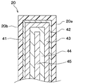
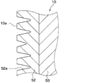
- the armature 20 uses low carbon steel as a base material, and the base material is subjected to a soft nitriding process and a coating process in order. For this reason, as shown in FIG. 2, the armature 20 includes a coating film 41, a white layer 42, a compound layer 43, and a diffusion layer 44 in order from the outside.
- FIG. 2 shows a cross section of the armature 20 in which the friction surface 20a is in an initial state. For this reason, in FIG. 2, the coating film 41 exists in the friction surface 20a.
- the coating film 41 is a rust prevention film for the purpose of rust prevention.
- the coating film 41 is formed of a synthetic resin, for example, a paint mainly composed of an epoxy resin system.
- Both the white layer 42 and the compound layer 43 are layers in which a nitride compound of an element in the base material is generated by a nitriding reaction of a part of the base material.
- the white layer 42 and the compound layer 43 are layers having a composition containing iron, nitrogen, and carbon, and are layers in which an ⁇ phase (Fe 2-3 N) and Fe 3 C are generated.
- the white layer 42 and the compound layer 43 are layers that are harder than the diffusion layer 44 and the base material 45 serving as the base of the white layer 42, that is, layers having higher hardness.
- the diffusion layer 44 is a layer in which nitrogen is diffused in the base material.
- the inside of the diffusion layer 44 is a base material 45.
- the thickness of the white layer 42 is several ⁇ m (for example, 2 ⁇ m or more and 10 ⁇ m or less).
- the thickness of the compound layer 43 is about 10 ⁇ m (for example, 8 ⁇ m or more and 15 ⁇ m or less).
- the thickness of the diffusion layer 44 is not less than 0.3 mm and not more than 0.5 mm.
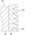
- the white layer 42 is a porous layer (ie, a porous layer) having a large number of holes 42a on the surface of the layer.
- the compound layer 43 is a dense layer that is not porous. Therefore, in the present embodiment, the white layer 42 is a contact surface side region including the friction surface 20a of the armature 20, and has a plurality of holes 42a opened in the friction surface 20a, and the nitriding reaction in the base material is unreacted. It is a contact surface side region that is harder than the portion.
- the plurality of holes 42a are holes that can hold the powder 42b generated by the wear of the contact surface side region due to the attachment / detachment of the rotor 10 and the armature 20 inside the hole 42a.
- . 3 shows a cross-sectional view of the vicinity of the friction surface 20a of the armature 20 in a state where the friction surface 20a has lost the coating film 41.
- the white layer 42 has a composition containing iron, nitrogen, and carbon.
- the white layer 42 is a layer in which Fe 2-3 N and Fe 3 C are generated. Other compositions may be used as long as they are harder than 45 and porous.
- the white layer 42 may have a composition that does not contain carbon and contains iron and nitrogen. Further, nitrides of elements other than Fe in the base material may be formed in the white layer 42.
- the white layer 42 is formed over the entire surface of the armature 20, but the white layer 42 may be formed on at least the friction surface 20 a of the surface of the armature 20. That's fine.
- the white layer 42 is preferably formed over the entire friction surface 20a, but the white layer 42 may be formed not only over the entire friction surface 20a but also in a partial region of the friction surface 20a.
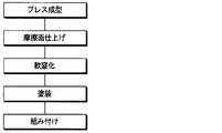
- the electromagnetic clutch 1 is manufactured by assembling the components of the electromagnetic clutch 1 such as the rotor 10 and the armature 20 described above. In this embodiment, as shown in FIG. 4, the assembly process is performed after the armature 20 is manufactured through the press molding process, the friction surface finishing process, the soft nitriding process, and the coating process.
- the base material is press molded into the shape of the armature 20.
- the friction surface finishing process the surface side portion of the base material press-molded into the shape of the armature 20 is cut and smoothed by cutting or polishing to form the friction surface 20a of the armature 20.
- the armature 20 having the friction surface 20a is formed by a machining process including a press molding process and a friction surface finishing process.
- the soft nitriding process is performed on the friction surface 20a of the armature 20 after the friction surface finishing process.
- salt bath soft nitriding is performed as the soft nitriding treatment.
- the salt bath soft nitriding treatment a general treatment method can be adopted. The heating temperature of the soft nitriding treatment is about 550 to 600 ° C.
- the white layer 42 and the compound layer 43 having the structure shown in FIG. 3 are formed on the surface layer of the friction surface 20 a of the armature 20.
- the base material inside the armature 20 is called a diffusion layer.
- the white layer 42 and the compound layer 43 are formed over the entire surface of the armature 20.
- the region of the surface of the armature 20 excluding at least the friction surface 20a is subjected to a coating treatment as a rust prevention treatment.
- the coating film 41 is formed on the outermost layer of the armature 20 in the region of the surface of the armature 20 excluding the friction surface 20a.
- the coating film 41 is formed on the entire surface of the armature 20 as described above.
- the armature 20 and the hubs 21, 22 and the like after painting are assembled. Further, the armature 20 and the rotor 10 are assembled to the compressor 2.
- a break-in operation (not shown) is performed.
- the electromagnetic coil 35 is energized and de-energized, that is, the electromagnetic clutch 1 is turned on and off repeatedly.
- the armature 20 and the rotor 10 are repeatedly attached and detached.
- the coating film 41 of the friction surface 20a of the armature 20 is removed.
- the friction surface 20a of the armature 20 and the friction surface 13a of the rotor 10 are oxidized, and the transmission torque increases. In this way, the electromagnetic clutch 1 having the structure shown in FIG. 1 is manufactured.
- the break-in operation is performed after the armature 20 and the rotor 10 are assembled to the compressor 2.
- the break-in operation is performed by assembling the armature 20 and the rotor 10 and the like to a rotating body different from the compressor 2. You may go.
- the armature 20 and the rotor 10 are assembled to the compressor 2 after the running-in operation.
- the porous white layer 42 is formed on the surface layer (that is, the surface side portion) of the friction surface 20a of the armature 20.
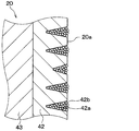
- the white layer 42 of the friction surface 20a of the armature 20 is abraded and hard wear powder is generated due to repeated attachment / detachment of the armature 20 and the rotor 10. Then, as shown in FIG. 5, the generated hard wear powder 42 b is trapped (that is, held) inside the hole 42 a of the white layer 42.
- the real contact area between the armature 20 and the rotor 10 at the time of adsorption is improved, and the hard wear powder 42b is interposed between the friction surface 20a of the armature 20 and the friction surface 13a of the rotor 10, so that the frictional resistance is reduced. improves.
- the time required for the break-in operation can be shortened, and the time required for manufacturing the clutch can be shortened.
- FIG. 6 shows the evaluation results of the transmission torque of the electromagnetic clutch 1 of the present embodiment and the electromagnetic clutch of Comparative Example 1.
- FIG. 6 is a measurement result of the transmission torque when the rotor 10 and the armature 20 are repeatedly interrupted (that is, contact and non-contact) while rotating the rotor 10.
- the electromagnetic clutch of Comparative Example 1 is different from the present embodiment in that the armature 20 is not subjected to soft nitriding, and the other configuration is the same as that of the present embodiment.
- the electromagnetic clutch of the comparative example 1 is the one in which the armature 20 is manufactured and assembled in the procedure shown in FIG. 7 described later, and corresponds to a conventional electromagnetic clutch.
- the transmission torque ratio is a ratio of the transmission torque when the magnitude of the transmission torque at the time when the number of on / off times of the electromagnetic clutch of Comparative Example 1 is 0 is 1.
- the contact load at the time of measurement of the transmission torque was set to 3000 N
- the rotor rotation speed at the time of interruption was set to 1000 rpm
- the contact load was set to 4000 N.
- the running-in operation is performed during the manufacturing process of the electromagnetic clutch 1, but the running-in operation may not be performed during the manufacturing process of the electromagnetic clutch 1.
- the initial use of the electromagnetic clutch 1 in the market corresponds to the break-in operation described above. Even in this case, in a short time from the start of use of the electromagnetic clutch 1, the transmission torque can be increased more than when both the friction surfaces 20a, 13a are in the initial state, and a stable high transmission torque can be obtained.
- the white layer 42 of the armature 20 is a layer formed by soft nitriding the base material constituting the armature 20. That is, the white layer 42 is a layer in which a part of the base material constituting the armature 20 undergoes a nitriding reaction to generate a nitride compound of an element in the base material. For this reason, unlike this embodiment, the number of parts can be reduced as compared with the case where the member corresponding to the white layer 42 is joined to the friction surface 20a of the armature 20.
- the armature 20 is manufactured and assembled to the compressor 2 together with other components in the procedure shown in FIG. Thereby, both high torque transmission property and high corrosion resistance are obtained as described below.
- the conventional electromagnetic clutch is generally manufactured through a press molding process, a painting process, an assembly process, and a friction surface finishing process in this order.
- the armature 20 and the hubs 21 and 22 are assembled.
- the soft nitriding step is performed before the coating step, the disappearance of the coating film due to the soft nitriding treatment can be avoided, and the high corrosion resistance of the electromagnetic clutch 1 can be ensured.
- the soft nitriding step is performed after the friction surface finishing step, it is possible to avoid the white layer 42 being scraped off and to obtain a high torque transmission property by the white layer 42. Can do.
- a friction material on the friction surface 13a of the rotor 10 in order to suppress wear of the white layer 42 due to repeated attachment / detachment of the armature 20 and the rotor 10.
- this friction material a general friction material used for improving the transmission torque can be used.
- salt bath soft nitriding is performed as soft nitriding, but gas soft nitriding may be performed.
- the heating temperature and gas concentration are set to conditions for forming the white layer 42.
- the heating temperature is set higher than the general temperature, or the gas concentration is set higher than the general concentration.
- the white layer 42 can be formed also by gas soft nitriding.
- the coating treatment is performed as the rust prevention treatment, but another rust prevention treatment may be performed.
- the other rust preventive treatment include plating treatment such as zinc plating and zinc-nickel plating.
- the plating layer also disappears or deteriorates at the heating temperature of the soft nitriding treatment. For this reason, it is desirable to perform the plating treatment after the soft nitriding treatment.
- the armature 20 was manufactured by performing a press molding process, a friction surface finishing process, a soft nitriding process, and a coating process in order, even if it performs another process between each process. Good. Even in this case, the same effect as that of the first embodiment can be obtained by sequentially performing the friction surface finishing process, the soft nitriding process, and the coating process.
- the friction surface finishing step may not be performed. Also in this case, the same effect as that of the first embodiment can be obtained by sequentially performing the soft nitriding step and the coating step after the press forming, that is, the processing step of forming the armature having the friction surface by machining.
- the soft nitriding step is performed after the friction surface finishing step. However, if it is possible to avoid the white layer 42 being scraped off, the soft nitriding step is performed before the friction surface finishing step. Also good.
- the white layer 42 is formed on the surface layer of the friction surface 20a of the armature 20.
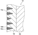
- the white layer 52 which has many holes 52a in the surface layer of 13a.
- the rotor 10 shown in FIG. 8 is obtained by subjecting a low-carbon steel base material to soft nitriding treatment and coating treatment in order.
- a layer 52, a compound layer 53, a diffusion layer 54, and a base material 55 are included.
- the coating film 51, the white layer 52, the compound layer 53, the diffusion layer 54, and the base material 55 correspond to the coating film 41, the white layer 42, the compound layer 43, the diffusion layer 44, and the base material 45 in FIG. It is.
- the white layer 52 is a contact surface side region including the friction surface 13a of the rotor 10 and has a plurality of holes 52a opened at the friction surface 13a, and the unreacted portion of the nitriding reaction in the base material It is a contact surface side region that is harder than 55.
- the plurality of holes 52a are holes that can hold the powder 52b generated by the abrasion of the contact surface side region due to the attachment / detachment of the rotor 10 and the armature 20 inside the hole 52a.
- FIG. 8 shows a cross section of the rotor 10 in which the friction surface 13a is in the initial state. For this reason, in FIG. 8, the coating film 51 exists in the friction surface 13a.
- the rotor 10 shown in FIG. 8 is manufactured by the same manufacturing method as the armature manufacturing method described in the first embodiment.
- the porous white layer 52 is formed on the surface layer (that is, the contact surface side portion) of the friction surface 13a of the rotor 10. For this reason, when the break-in operation is started, the white layer 52 is abraded and hard wear powder is generated due to repeated desorption of the armature 20 and the rotor 10. Then, as shown in FIG. 11, the generated hard wear powder 52 b is trapped (that is, held) inside the hole 52 a of the white layer 52. Thereby, the effect similar to 1st Embodiment is acquired.
- a white layer may be formed on both the surface layer of the friction surface 20a of the armature 20 and the surface layer of the friction surface 13a of the rotor 10.
- the low carbon steel is used as the base material of the rotor 10 and the armature 20, but another steel material that is a magnetic material may be used.
- other steel materials include SPHC (hot rolled steel plate) and SPCC (cold rolled steel plate).
- the clutch of the present disclosure is applied to the electromagnetic clutch that attracts the armature 20 to the rotor 10 by the magnetic force generated by the electromagnetic coil.
- the clutch of the present disclosure is used as a clutch that uses a permanent magnet. It is also possible to apply.
- a clutch that uses a permanent magnet maintains, for example, the connection state between the rotor and the armature by the magnetic force of the permanent magnet, and the same direction as the flow direction of the magnetic flux by the permanent magnet with respect to the magnetic circuit formed by the permanent magnet.
- a magnetic flux is generated by the electromagnetic coil so as to give a magnetic flux in the reverse direction. As a result, the connection and disconnection of the rotor and armature are switched.
- elements constituting the embodiment are not necessarily indispensable unless explicitly stated as essential and clearly considered essential in principle. Needless to say. Further, in each of the above embodiments, when numerical values such as the number, numerical value, quantity, range, etc. of the constituent elements of the embodiment are mentioned, it is clearly limited to a specific number when clearly indicated as essential and in principle. The number is not limited to the specific number except for the case. In each of the above embodiments, when referring to the material, shape, positional relationship, etc. of the constituent elements, etc., unless otherwise specified, or in principle limited to a specific material, shape, positional relationship, etc. The material, shape, positional relationship, etc. are not limited.
Landscapes
- Engineering & Computer Science (AREA)
- Chemical & Material Sciences (AREA)
- General Engineering & Computer Science (AREA)
- Mechanical Engineering (AREA)
- Organic Chemistry (AREA)
- Metallurgy (AREA)
- Materials Engineering (AREA)
- Chemical Kinetics & Catalysis (AREA)
- Physics & Mathematics (AREA)
- Electromagnetism (AREA)
- Mechanical Operated Clutches (AREA)
- Braking Arrangements (AREA)
- Manufacture Of Motors, Generators (AREA)
Abstract
Description
鉄鋼材料を母材とし、駆動源からの回転駆動力を受けて回転するロータと、
鉄鋼材料を母材とし、磁力によってロータに吸着されることにより、回転駆動力が伝達されるアーマチャとを備え、
アーマチャは、アーマチャがロータに吸着された際に相手側と接触する接触面を含む接触面側領域を有し、
接触面側領域は、接触面にて開口する複数の孔を有するとともに、母材の一部の窒化反応によって母材中の元素の窒化化合物が生成しており、母材における窒化反応の未反応部分よりも硬質である。
鉄鋼材料を母材とし、駆動源からの回転駆動力を受けて回転するロータと、
鉄鋼材料を母材とし、磁力によってロータに吸着されることにより、回転駆動力が伝達されるアーマチャとを備え、
アーマチャは、アーマチャがロータに吸着された際に相手側と接触する接触面を含む接触面側領域を有し、
接触面側領域は、接触面にて開口する複数の孔を有するとともに、母材中の元素の窒化化合物が生成しており、母材よりも硬質である。
鉄鋼材料を母材とし、駆動源からの回転駆動力を受けて回転するロータと、
鉄鋼材料を母材とし、磁力によってロータに吸着されることにより、回転駆動力が伝達されるアーマチャとを備え、
ロータは、アーマチャがロータに吸着された際に相手側と接触する接触面を含む接触面側領域を有し、
接触面側領域は、接触面にて開口する複数の孔を有するとともに、母材の一部の窒化反応によって母材中の元素の窒化化合物が生成しており、母材における窒化反応の未反応部分よりも硬質である。
鉄鋼材料を母材とし、駆動源からの回転駆動力を受けて回転するロータと、
鉄鋼材料を母材とし、磁力によってロータに吸着されることにより、回転駆動力が伝達されるアーマチャとを備え、
ロータは、アーマチャがロータに吸着された際に相手側と接触する接触面を含む接触面側領域を有し、
接触面側領域は、接触面にて開口する複数の孔を有するとともに、母材中の元素の窒化化合物が生成しており、母材よりも硬質である。
母材に対する機械加工によって、アーマチャがロータに吸着された際に相手側と接触する接触面を有するアーマチャを形成する加工工程と、
加工工程後に、アーマチャの少なくとも接触面に対して軟窒化処理を施すことによって、接触面にて開口する複数の孔を有するとともに、母材よりも硬質である接触面側領域を形成する軟窒化工程と、
軟窒化工程後に、アーマチャの表面のうち少なくとも接触面を除く領域に対して防錆処理を施して防錆膜を形成する防錆工程とを備える。
加工工程は、アーマチャの形状にプレス成型された母材の表面を削ることによってアーマチャの接触面を形成する仕上げ工程を有する。
母材に対する機械加工によって、アーマチャがロータに吸着された際に相手側と接触する接触面を有するロータを形成する加工工程と、
加工工程後に、ロータの少なくとも接触面に対して軟窒化処理を施すことによって、接触面にて開口する複数の孔を有するとともに、母材よりも硬質である接触面側領域を形成する軟窒化工程と、
軟窒化工程後に、ロータの表面のうち少なくとも接触面を除く領域に対して防錆処理を施して防錆膜を形成する防錆工程とを備える。
加工工程は、ロータの形状にプレス成型された母材の表面を削ることによってロータの接触面を形成する仕上げ工程を有する。
図1に示す第1実施形態の電磁クラッチ1は、車両走行用駆動力を出力する駆動源としてのエンジンから回転駆動力を得て、圧縮機構を回転駆動させる圧縮機2の駆動機構に使用されるものである。したがって、本実施形態では、エンジンが駆動源であり、圧縮機2が従動側機器である。
本開示は上記した実施形態に限定されるものではなく、下記のように、請求の範囲に記載した範囲内において適宜変更が可能である。
Claims (11)
- クラッチであって、
鉄鋼材料を母材とし、駆動源からの回転駆動力を受けて回転するロータ(10)と、
鉄鋼材料を母材とし、磁力によって前記ロータに吸着されることにより、前記回転駆動力が伝達されるアーマチャ(20)とを備え、
前記アーマチャは、前記アーマチャが前記ロータに吸着された際に相手側と接触する接触面(20a)を含む接触面側領域(42)を有し、
前記接触面側領域は、前記接触面にて開口する複数の孔(42a)を有するとともに、前記母材の一部の窒化反応によって前記母材中の元素の窒化化合物が生成しており、前記母材における前記窒化反応の未反応部分(45)よりも硬質であるクラッチ。 - クラッチであって、
鉄鋼材料を母材とし、駆動源からの回転駆動力を受けて回転するロータ(10)と、
鉄鋼材料を母材とし、磁力によって前記ロータに吸着されることにより、前記回転駆動力が伝達されるアーマチャ(20)とを備え、
前記アーマチャは、前記アーマチャが前記ロータに吸着された際に相手側と接触する接触面(20a)を含む接触面側領域(42)を有し、
前記接触面側領域は、前記接触面にて開口する複数の孔(42a)を有するとともに、前記母材中の元素の窒化化合物が生成しており、前記母材よりも硬質であるクラッチ。 - クラッチであって、
鉄鋼材料を母材とし、駆動源からの回転駆動力を受けて回転するロータ(10)と、
鉄鋼材料を母材とし、磁力によって前記ロータに吸着されることにより、前記回転駆動力が伝達されるアーマチャ(20)とを備え、
前記ロータは、前記アーマチャが前記ロータに吸着された際に相手側と接触する接触面(13a)を含む接触面側領域(52)を有し、
前記接触面側領域は、前記接触面にて開口する複数の孔(52a)を有するとともに、前記母材の一部の窒化反応によって前記母材中の元素の窒化化合物が生成しており、前記母材における前記窒化反応の未反応部分(55)よりも硬質であるクラッチ。 - クラッチであって、
鉄鋼材料を母材とし、駆動源からの回転駆動力を受けて回転するロータ(10)と、
鉄鋼材料を母材とし、磁力によって前記ロータに吸着されることにより、前記回転駆動力が伝達されるアーマチャ(20)とを備え、
前記ロータは、前記アーマチャが前記ロータに吸着された際に相手側と接触する接触面(13a)を含む接触面側領域(52)を有し、
前記接触面側領域は、前記接触面にて開口する複数の孔(52a)を有するとともに、前記母材中の元素の窒化化合物が生成しており、前記母材よりも硬質であるクラッチ。 - 前記接触面側領域は、厚さが2μm以上10μm以下である請求項1ないし4のいずれか1つに記載のクラッチ。
- 前記複数の孔は、前記ロータと前記アーマチャの脱着による、前記接触面側領域の摩耗によって生成される粉を、内部に保持することが可能な孔である請求項1ないし5のいずれか1つに記載のクラッチ。
- 鉄鋼材料を母材とし、駆動源からの回転駆動力を受けて回転するロータ(10)と、
鉄鋼材料を母材とし、磁力によって前記ロータに吸着されることにより、前記回転駆動力が伝達されるアーマチャ(20)とを備えたクラッチの製造方法であって、
前記母材に対する機械加工によって、前記アーマチャが前記ロータに吸着された際に相手側と接触する接触面(20a)を有する前記アーマチャを形成する加工工程と、
前記加工工程後に、前記アーマチャの少なくとも前記接触面に対して軟窒化処理を施すことによって、前記接触面にて開口する複数の孔(42a)を有するとともに、前記母材(45)よりも硬質である接触面側領域(42)を形成する軟窒化工程と、
前記軟窒化工程後に、前記アーマチャの表面のうち少なくとも前記接触面を除く領域に対して防錆処理を施して防錆膜(41)を形成する防錆工程とを備えるクラッチの製造方法。 - 前記加工工程は、前記アーマチャの形状にプレス成型された前記母材の表面を削ることによって前記アーマチャの前記接触面を形成する仕上げ工程を有する請求項7に記載のクラッチの製造方法。
- 鉄鋼材料を母材とし、駆動源からの回転駆動力を受けて回転するロータ(10)と、
鉄鋼材料を母材とし、磁力によって前記ロータに吸着されることにより、前記回転駆動力が伝達されるアーマチャ(20)とを備えたクラッチの製造方法であって、
前記母材に対する機械加工によって、前記アーマチャが前記ロータに吸着された際に相手側と接触する接触面(13a)を有する前記ロータを形成する加工工程と、
前記加工工程後に、前記ロータの少なくとも前記接触面に対して軟窒化処理を施すことによって、前記接触面にて開口する複数の孔(52a)を有するとともに、前記母材(55)よりも硬質である接触面側領域(52)を形成する軟窒化工程と、
前記軟窒化工程後に、前記ロータの表面のうち少なくとも前記接触面を除く領域に対して防錆処理を施して防錆膜(51)を形成する防錆工程とを備えるクラッチの製造方法。 - 前記加工工程は、前記ロータの形状にプレス成型された前記母材の表面を削ることによって前記ロータの前記接触面を形成する仕上げ工程を有する請求項9に記載のクラッチの製造方法。
- 前記複数の孔は、前記ロータと前記アーマチャの脱着による、前記接触面側領域の摩耗によって生成される粉を、内部に保持することが可能な孔である請求項7ないし10のいずれか1つに記載のクラッチの製造方法。
Priority Applications (4)
| Application Number | Priority Date | Filing Date | Title |
|---|---|---|---|
| US15/557,491 US20180058516A1 (en) | 2015-05-28 | 2016-05-23 | Clutch |
| CN201680030033.8A CN107614914B (zh) | 2015-05-28 | 2016-05-23 | 离合器 |
| DE112016002404.5T DE112016002404T5 (de) | 2015-05-28 | 2016-05-23 | Kupplung |
| JP2017520696A JP6477873B2 (ja) | 2015-05-28 | 2016-05-23 | クラッチ |
Applications Claiming Priority (2)
| Application Number | Priority Date | Filing Date | Title |
|---|---|---|---|
| JP2015108827 | 2015-05-28 | ||
| JP2015-108827 | 2015-05-28 |
Publications (1)
| Publication Number | Publication Date |
|---|---|
| WO2016190275A1 true WO2016190275A1 (ja) | 2016-12-01 |
Family
ID=57392803
Family Applications (1)
| Application Number | Title | Priority Date | Filing Date |
|---|---|---|---|
| PCT/JP2016/065149 Ceased WO2016190275A1 (ja) | 2015-05-28 | 2016-05-23 | クラッチ |
Country Status (5)
| Country | Link |
|---|---|
| US (1) | US20180058516A1 (ja) |
| JP (1) | JP6477873B2 (ja) |
| CN (1) | CN107614914B (ja) |
| DE (1) | DE112016002404T5 (ja) |
| WO (1) | WO2016190275A1 (ja) |
Citations (4)
| Publication number | Priority date | Publication date | Assignee | Title |
|---|---|---|---|---|
| JPH06346927A (ja) * | 1993-06-07 | 1994-12-20 | Matsushita Electric Ind Co Ltd | 電磁クラッチ |
| JPH08158037A (ja) * | 1994-12-05 | 1996-06-18 | Sumitomo Metal Ind Ltd | 耐転動疲労性に優れた窒化処理品とその製造方法 |
| JP2006117982A (ja) * | 2004-10-20 | 2006-05-11 | Exedy Corp | 車両の駆動系部品の製造方法 |
| JP2010255843A (ja) * | 2009-03-30 | 2010-11-11 | Sinfonia Technology Co Ltd | 電磁摩擦クラッチ、及び電磁摩擦ブレーキ |
Family Cites Families (10)
| Publication number | Priority date | Publication date | Assignee | Title |
|---|---|---|---|---|
| US2921659A (en) * | 1957-04-30 | 1960-01-19 | Ite Circuit Breaker Ltd | Electromagnetic clutch lamination treatment |
| US5123157A (en) * | 1990-04-24 | 1992-06-23 | Tesma International Inc. | Method of making a rotor for an electromagnetic clutch |
| JP2947640B2 (ja) * | 1991-06-21 | 1999-09-13 | 日本ピストンリング株式会社 | シンクロナイザーリング |
| US5670213A (en) * | 1995-03-14 | 1997-09-23 | Hilite Industries, Inc. | Process for increasing torque generated by a clutch |
| US5735375A (en) * | 1996-05-31 | 1998-04-07 | Dana Corporation | Nitrocarburized component for an electromagnetic friction clutch assembly |
| JP5813132B2 (ja) * | 2011-11-24 | 2015-11-17 | 三菱重工オートモーティブサーマルシステムズ株式会社 | 電磁クラッチ及び電磁クラッチのアーマチャ製造方法 |
| JP2013245718A (ja) * | 2012-05-24 | 2013-12-09 | Calsonic Kansei Corp | 電磁クラッチ |
| US20140017101A1 (en) * | 2012-07-10 | 2014-01-16 | GM Global Technology Operations LLC | Clutch subassembly and clutched supercharger made using the same |
| EP2703517B1 (en) * | 2012-08-31 | 2018-10-24 | Akebono Brake Industry Co., Ltd. | Vehicular disc brake rotor and manufacturing method of vehicular disc brake rotor |
| JP6115140B2 (ja) * | 2013-01-15 | 2017-04-19 | 株式会社ジェイテクト | 摺動部材の製造方法およびクラッチプレートの製造方法 |
-
2016
- 2016-05-23 WO PCT/JP2016/065149 patent/WO2016190275A1/ja not_active Ceased
- 2016-05-23 JP JP2017520696A patent/JP6477873B2/ja not_active Expired - Fee Related
- 2016-05-23 CN CN201680030033.8A patent/CN107614914B/zh not_active Expired - Fee Related
- 2016-05-23 US US15/557,491 patent/US20180058516A1/en not_active Abandoned
- 2016-05-23 DE DE112016002404.5T patent/DE112016002404T5/de not_active Withdrawn
Patent Citations (4)
| Publication number | Priority date | Publication date | Assignee | Title |
|---|---|---|---|---|
| JPH06346927A (ja) * | 1993-06-07 | 1994-12-20 | Matsushita Electric Ind Co Ltd | 電磁クラッチ |
| JPH08158037A (ja) * | 1994-12-05 | 1996-06-18 | Sumitomo Metal Ind Ltd | 耐転動疲労性に優れた窒化処理品とその製造方法 |
| JP2006117982A (ja) * | 2004-10-20 | 2006-05-11 | Exedy Corp | 車両の駆動系部品の製造方法 |
| JP2010255843A (ja) * | 2009-03-30 | 2010-11-11 | Sinfonia Technology Co Ltd | 電磁摩擦クラッチ、及び電磁摩擦ブレーキ |
Also Published As
| Publication number | Publication date |
|---|---|
| US20180058516A1 (en) | 2018-03-01 |
| CN107614914A (zh) | 2018-01-19 |
| DE112016002404T5 (de) | 2018-03-01 |
| CN107614914B (zh) | 2019-04-09 |
| JPWO2016190275A1 (ja) | 2017-09-28 |
| JP6477873B2 (ja) | 2019-03-06 |
Similar Documents
| Publication | Publication Date | Title |
|---|---|---|
| JP6965775B2 (ja) | 電磁クラッチ | |
| US9982725B2 (en) | Electromagnetic clutch | |
| WO2014076867A1 (ja) | クラッチ機構 | |
| JP6260423B2 (ja) | クラッチ | |
| JP6477873B2 (ja) | クラッチ | |
| JP6569600B2 (ja) | クラッチおよびその製造方法 | |
| US20190264758A1 (en) | Power transmission device | |
| WO2019216070A1 (ja) | 電磁クラッチ | |
| JP6256119B2 (ja) | 摩擦クラッチ | |
| JP6645415B2 (ja) | 動力伝達装置 | |
| JP4888801B2 (ja) | 電磁クラッチ | |
| JP2014137081A (ja) | 電磁クラッチ | |
| JP6747399B2 (ja) | 動力伝達装置 | |
| WO2016103665A1 (ja) | 電磁クラッチおよびその製造方法 | |
| JPH08219179A (ja) | 電磁クラッチ | |
| US20150292574A1 (en) | Clutch mechanism | |
| JPH11132257A (ja) | 電磁クラッチ | |
| JPH0617848A (ja) | 電磁クラッチ | |
| JP2016121802A (ja) | 電磁クラッチおよびその製造方法 | |
| WO2019239837A1 (ja) | 動力伝達装置 | |
| WO2018092433A1 (ja) | 軸受構造体およびその軸受構造体の製造方法 | |
| JPS58193939A (ja) | 電磁スプリングクラツチ | |
| JP2020118183A (ja) | クラッチの製造方法 | |
| JP2008025598A (ja) | 電磁クラッチ | |
| JPH051032U (ja) | マグネツトクラツチ |
Legal Events
| Date | Code | Title | Description |
|---|---|---|---|
| 121 | Ep: the epo has been informed by wipo that ep was designated in this application |
Ref document number: 16799980 Country of ref document: EP Kind code of ref document: A1 |
|
| ENP | Entry into the national phase |
Ref document number: 2017520696 Country of ref document: JP Kind code of ref document: A |
|
| WWE | Wipo information: entry into national phase |
Ref document number: 15557491 Country of ref document: US |
|
| WWE | Wipo information: entry into national phase |
Ref document number: 112016002404 Country of ref document: DE |
|
| 122 | Ep: pct application non-entry in european phase |
Ref document number: 16799980 Country of ref document: EP Kind code of ref document: A1 |