WO2016190133A1 - 打込機 - Google Patents
打込機 Download PDFInfo
- Publication number
- WO2016190133A1 WO2016190133A1 PCT/JP2016/064316 JP2016064316W WO2016190133A1 WO 2016190133 A1 WO2016190133 A1 WO 2016190133A1 JP 2016064316 W JP2016064316 W JP 2016064316W WO 2016190133 A1 WO2016190133 A1 WO 2016190133A1
- Authority
- WO
- WIPO (PCT)
- Prior art keywords
- cylinder
- driving machine
- housing
- central axis
- holder
- Prior art date
- Legal status (The legal status is an assumption and is not a legal conclusion. Google has not performed a legal analysis and makes no representation as to the accuracy of the status listed.)
- Ceased
Links
Images






Classifications
-
- B—PERFORMING OPERATIONS; TRANSPORTING
- B25—HAND TOOLS; PORTABLE POWER-DRIVEN TOOLS; MANIPULATORS
- B25C—HAND-HELD NAILING OR STAPLING TOOLS; MANUALLY OPERATED PORTABLE STAPLING TOOLS
- B25C7/00—Accessories for nailing or stapling tools, e.g. supports
-
- B—PERFORMING OPERATIONS; TRANSPORTING
- B25—HAND TOOLS; PORTABLE POWER-DRIVEN TOOLS; MANIPULATORS
- B25C—HAND-HELD NAILING OR STAPLING TOOLS; MANUALLY OPERATED PORTABLE STAPLING TOOLS
- B25C1/00—Hand-held nailing tools; Nail feeding devices
- B25C1/008—Safety devices
-
- B—PERFORMING OPERATIONS; TRANSPORTING
- B25—HAND TOOLS; PORTABLE POWER-DRIVEN TOOLS; MANIPULATORS
- B25C—HAND-HELD NAILING OR STAPLING TOOLS; MANUALLY OPERATED PORTABLE STAPLING TOOLS
- B25C1/00—Hand-held nailing tools; Nail feeding devices
- B25C1/04—Hand-held nailing tools; Nail feeding devices operated by fluid pressure, e.g. by air pressure
- B25C1/047—Mechanical details
-
- B—PERFORMING OPERATIONS; TRANSPORTING
- B25—HAND TOOLS; PORTABLE POWER-DRIVEN TOOLS; MANIPULATORS
- B25C—HAND-HELD NAILING OR STAPLING TOOLS; MANUALLY OPERATED PORTABLE STAPLING TOOLS
- B25C1/00—Hand-held nailing tools; Nail feeding devices
- B25C1/06—Hand-held nailing tools; Nail feeding devices operated by electric power
-
- B—PERFORMING OPERATIONS; TRANSPORTING
- B25—HAND TOOLS; PORTABLE POWER-DRIVEN TOOLS; MANIPULATORS
- B25C—HAND-HELD NAILING OR STAPLING TOOLS; MANUALLY OPERATED PORTABLE STAPLING TOOLS
- B25C1/00—Hand-held nailing tools; Nail feeding devices
- B25C1/08—Hand-held nailing tools; Nail feeding devices operated by combustion pressure
-
- B—PERFORMING OPERATIONS; TRANSPORTING
- B25—HAND TOOLS; PORTABLE POWER-DRIVEN TOOLS; MANIPULATORS
- B25F—COMBINATION OR MULTI-PURPOSE TOOLS NOT OTHERWISE PROVIDED FOR; DETAILS OR COMPONENTS OF PORTABLE POWER-DRIVEN TOOLS NOT PARTICULARLY RELATED TO THE OPERATIONS PERFORMED AND NOT OTHERWISE PROVIDED FOR
- B25F5/00—Details or components of portable power-driven tools not particularly related to the operations performed and not otherwise provided for
- B25F5/006—Vibration damping means
-
- B—PERFORMING OPERATIONS; TRANSPORTING
- B25—HAND TOOLS; PORTABLE POWER-DRIVEN TOOLS; MANIPULATORS
- B25F—COMBINATION OR MULTI-PURPOSE TOOLS NOT OTHERWISE PROVIDED FOR; DETAILS OR COMPONENTS OF PORTABLE POWER-DRIVEN TOOLS NOT PARTICULARLY RELATED TO THE OPERATIONS PERFORMED AND NOT OTHERWISE PROVIDED FOR
- B25F5/00—Details or components of portable power-driven tools not particularly related to the operations performed and not otherwise provided for
- B25F5/008—Cooling means
Definitions
- the present invention relates to a driving machine for driving a stopper into a driven member.
- a driving machine for driving a stopper into a driven member is described in Patent Document 1.
- the driving machine described in Patent Document 1 can operate along a housing, a cylindrical guide member provided in the housing, a damper provided in the housing, a bellows arranged in the housing, and the guide member A piston as a movable member.
- a first end of the guide member in the central axis direction is connected to the housing.
- the bellows is extendable, the first end of the bellows is connected to the piston, and the second end of the bellows is fixed to the housing. Compressed air is enclosed in the bellows to form a compression chamber.
- the housing includes a wall portion, and the damper is supported by the wall portion.
- the wall portion extends in the radial direction of the guide member, and the wall portion is connected to a second end portion in the central axis direction of the guide member.
- a driver blade as a striker is fixed to the piston.
- the driving machine described in Patent Document 1 includes a motor provided in the housing, a gear that transmits the rotational force of the motor to the cam, a protrusion provided on the cam, a locking portion provided on the piston, And a damper provided in the housing. Furthermore, the driving machine described in Patent Document 1 includes a push rod that is movable with respect to the housing and a trigger that is operated by an operator.
- the driver blade drives the stopper into the driven member, and when the piston collides with the damper, the damper reduces and attenuates the impact load. Further, the motor stops after the driver blade has driven the stopper into the driven member, and the piston stops in contact with the damper.
- Patent Document 1 has a problem that the load received by the damper is transmitted to the guide member via the wall, and the guide member receives the load in the central axis direction.
- An object of the present invention is to provide a driving machine capable of reducing a load in a central axis direction applied to a guide member.
- An embodiment of the present invention is a driving machine for driving a stopper into a driven member, an impactor for applying a driving force to the stopper, an operation device that can operate with the impactor, and a housing.
- An operating member provided, a guide member for guiding the operation of the operating member, a holder provided in the housing and supporting the guide member, and interposed between the holder and the housing, and A first cushioning material that receives a load in the movement direction of the movement member applied to the holder.
- the invention of one embodiment can reduce the load in the central axis direction applied to the guide member.
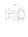
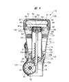
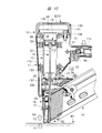
- FIG. 2 is a front sectional view taken along the line AA of the driving machine shown in FIG. 1. It is front sectional drawing which shows the state which the driver blade of the driving machine shown in FIG. 1 moved backward.
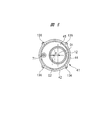
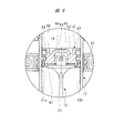
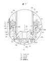
- FIG. 2 is a plan sectional view taken along line BB of the driving machine shown in FIG. 1. It is sectional drawing of the support structure of the cylinder provided in the driving machine shown in FIG. It is sectional drawing of the support structure of the holder provided in the driving machine shown in FIG. It is an expanded sectional view of the pressure accumulation container provided in the driving machine shown in FIG.
- the driving machine 10 shown in FIGS. 1 to 5 includes a housing 11, which includes a cylinder case portion 11a that accommodates a cylinder 12, and a motor case portion 11b that is integrated with the tip of the cylinder case portion 11a. It has.
- a handle portion 11c is integrated with the top side of the cylinder case portion 11a along the motor case portion 11b.
- a connecting portion 11d is integrally provided between the distal end portion of the handle portion 11c and the distal end portion of the motor case portion 11b.
- the housing 11 includes the cylinder case portion 11a, the motor case portion 11b, the handle portion 11c, and the connecting portion 11d.
- the housing 11 has two housing halves, and the housing 11 is assembled by fixing the two housing halves together.
- the two housing halves are each molded separately from a synthetic resin such as nylon or polycarbonate.
- a cylindrical cylinder 12 is accommodated in the cylinder case portion 11a, and the cylinder 12 has a cylinder hole 12a.
- a piston 13 is movably provided in the cylinder hole 12a.
- the operation direction of the piston 13 is the direction of the central axis O1 of the cylinder 12.
- the cylinder 12 is integrally formed of a metal material, for example, aluminum.
- the piston 13 can reciprocate between the tip portion 141 and the top portion 140 of the cylinder 12 with the top end of the cylinder 12 shown in FIG. 8 as the top portion 140 and the lower end of the cylinder 12 shown in FIG. 7 as the tip portion 141.
- the top part 140 and the tip part 141 of the cylinder 12 are located farthest from each other in the direction of the central axis O1 of the cylinder 12.
- the direction of the central axis O1 is a direction parallel to the central axis O1, that is, a direction along the central axis O1.
- a piston chamber 14 is formed by the top surface of the piston 13.
- a driver blade 15 is connected to the piston 13.
- a nose portion 16 is provided in the cylinder case portion 11a of the housing 11, an injection port 17 is provided in the nose portion 16, and the driver blade 15 is supported in the injection port 17 so as to be capable of reciprocating in the direction of the central axis O1.
- the driver blade 15 is disposed from the inside of the cylinder case portion 11 a to the injection port 17 and the outside of the housing 11.
- a magazine 18 that houses a number of stoppers 82 is attached to the housing 11, and the stoppers 82 in the magazine 18 are supplied to the injection port 17 one by one.
- the driver blade 15 applies driving force to the stopper 82 supplied to the injection port 17 and drives the stopper 82 into a member to be driven such as wood or gypsum board.
- the operator grips the handle portion 11c when driving the stopper 82, and makes the central axis O1 of the cylinder 12 perpendicular to the surface of the driven member.
- the motor case portion 11b is arranged so as to be shifted to one side in the width direction of the driving machine 10 with respect to the handle portion 11c, and the magazine 18 is arranged in the width direction opposite to the motor case portion 11b. Inclined. As shown in FIG. 1, the magazine 18 is inclined downward from the rear end portion toward the front end portion. However, the magazine 18 may be arranged at a right angle to the cylinder 12.
- protrusions 21, 22, and 130 that protrude from the inner surface of the cylinder case 11 a are provided.
- the protrusions 21, 22, and 130 are arranged at an interval in the direction of the central axis O1.
- the protruding portions 22 and 130 are disposed between the protruding portion 21 and the nose portion 16 in the direction of the central axis O1.
- the protruding portion 130 is disposed between the protruding portion 22 and the nose portion 16 in the direction of the central axis O1.
- the protrusions 21, 22, and 130 are annularly arranged in the cylinder case 11 a, the protrusion 21 forms a support hole 21 a, the protrusion 22 forms a support hole 22 a, and the protrusion 130 is A support hole 130a is formed.
- the support holes 21a, 22a, 130a are arranged concentrically, and a part of the cylinder 12 in the direction of the central axis O1 is arranged in the support holes 21a, 22a, 130a.
- the inner diameter of the support hole 130a is larger than the inner diameter of the support hole 22a.
- a support groove 132 is provided between the protrusion 22 and the protrusion 130.
- the support groove 132 is annular.
- the holder 23 is provided in the cylinder case portion 11 a at a location including the tip portion 141 in the direction of the central axis O ⁇ b> 1 in the cylinder 12.
- the holder 23 is connected to the nose portion 16, and the cylinder 12 is coupled to the holder 23.
- the place where the holder 23 is connected to the cylinder 12 is an end portion closer to the nose portion 16.
- the holder 23 includes an end wall portion 23a and a cylindrical portion 23b.
- the inner diameter of the cylindrical portion 23 b is larger than the outer diameter of the cylinder 12, and the end wall portion 23 a has a through hole 24.
- the driver blade 15 is movably disposed in the through hole 24.
- the holder 23 is disposed between the protruding portion 22 and the nose portion 16 in the direction of the central axis O1.
- a male screw 12b is formed on the outer peripheral surface of the cylinder 12, and a female screw 23d is formed on the inner peripheral surface of the cylindrical portion 23b.
- the cylinder 12 and the holder 23 are screwed and fixed to each other in the direction of the central axis O1. In the direction of the central axis O1, the arrangement area of the cylinder 12 and the arrangement area of the holder 23 overlap to form an overlapping portion X1, and the cylinder 12 and the holder 23 are screwed together at the overlapping portion X1.
- a flange 131 projecting outward in the radial direction from the outer peripheral surface of the cylindrical portion 23b is provided.
- the flange 131 is provided in an annular shape, and the flange 131 is disposed in the support groove 132.
- the outer diameter of the flange 131 is larger than the inner diameter of the support holes 22a and 130a.
- Anti-vibration rubber 133 is disposed in the support groove 132.
- the anti-vibration rubber 133 is annular and has a U-shaped cross section.
- the anti-vibration rubber 133 covers the flange 131 over the entire circumference.
- Anti-vibration rubber 133 is interposed between the flange 131 and the protrusions 22 and 130.
- the flange 131 engages with the protrusions 22 and 130 via the vibration isolating rubber 133 in the direction of the central axis O1. That is, the holder 23 is positioned in the direction of the central axis O1 by the protrusions 22 and 130. The holder 23 is positioned in the radial direction by the inner surface of the support groove 132.
- FIG. 1 and 3 show a state in which the driver blade 15 is driven out by the piston 13 and the piston 13 is in the advanced position.
- the forward movement position is a bottom dead center where the piston 13 is pressed against the damper 25.
- FIG. 4 shows a state where the piston 13 is pushed by the driver blade 15 and the piston 13 is in the retracted position.
- the retracted position is the top dead center where the piston 13 is farthest from the damper 25.
- the end wall 23a is provided with a recess 23c, and the damper 25 is disposed in the recess 23c.
- the damper 25 is integrally formed of a rubber-like elastic body or urethane, and the arrangement area of the damper 25 includes the arrangement position of the tip portion 141 in the direction of the central axis O1.
- a rotating disk 26 is provided for moving the piston 13 to the retracted position in FIG.
- a cylindrical housing portion 137 is provided in the cylinder case portion 11 a, and the rotating disk 26 is housed in the housing portion 137.
- the accommodating portion 137 is integrally formed continuously with the holder 23.
- the rotating disk 26 is provided on a drive shaft 27, and the drive shaft 27 is rotatably supported by bearings 28a and 28b attached to the motor case portion 11b as shown in FIG.
- a rack 31 having a plurality of rack claws 31 a is attached to the driver blade 15, and a plurality of pins 32 that engage and disengage from the rack claws 31 a are attached to the rotating disk 26 at intervals in the circumferential direction.
- FIGS. 1 and 3 the rotation center axis R of the rotary disk 26 is shifted by a distance C in the radial direction of the cylinder 12 with respect to the center axis O1 of the cylinder 12, and substantially about the center axis O1. It is a right angle.
- FIG. 1 shows a cross section of a portion of the rotation center axis R and a cross section of a portion of the center axis O1.
- the center axis O1 is an imaginary line or a center line or an axis line determined from the viewpoint of mechanical engineering, and the center axis O1 does not exist as an object.
- an electric motor 33 is provided in the motor case portion 11b.
- the electric motor 33 includes a stator 33a that is fixed to the motor case portion 11b, and a rotor 33b that is rotatably provided in the stator 33a.
- a cooling fan 35 is attached to the motor shaft 34 provided in the rotor 33 b, and cooling air for cooling the electric motor 33 is generated in the housing 11 by the cooling fan 35.
- the housing 11 is provided with an unillustrated intake hole for introducing outside air and an unillustrated exhaust hole for discharging the air after cooling the motor.
- a planetary gear type speed reducer 36 is provided in the motor case 11 b, an input shaft 37 a of the speed reducer 36 is connected to the motor shaft 34, and an output shaft 37 b of the speed reducer 36 is connected to the drive shaft 27.
- the motor shaft 34 is rotatably supported by a bearing 38a attached to the motor case portion 11b.
- the motor shaft 34 is coupled to the input shaft 37a, and a reduction gear holder 39 is provided in the motor case portion 11b.
- a bearing 38 b is provided in the reduction gear holder 39.
- the input shaft 37a is rotatably supported by a bearing 38b.
- a gear case 138 is provided in the motor case portion 11 b, and the reduction gear 36 is accommodated in the gear case 138.
- the gear case 138 is fixed to the holder 23 using a fixing element.
- a battery 40 is attached to the connecting portion 11d.
- the battery 40 can be attached to and detached from the connecting portion 11 d, and the battery 40 supplies electric power to the electric motor 33.
- the battery 40 includes a storage case 40a and a plurality of battery cells stored in the storage case 40a.
- the battery cell is a secondary battery composed of a lithium ion battery, a nickel hydrogen battery, a lithium ion polymer battery, a nickel cadmium battery, or the like.
- a pressure accumulating container 41 is provided outside the cylinder 12 in the direction of the central axis O ⁇ b> 1 of the cylinder 12.
- the cylinder case portion 11a includes an opening portion 11e, and the top portion 140 of the cylinder 12 in the direction of the central axis O1 is disposed outside the cylinder case portion 11a through the opening portion 11e.
- the pressure accumulating container 41 has a main body 134 and a holder 139. Both the main body 134 and the holder 139 are formed of a metal material.
- the main body 134 includes a cylindrical portion 44 and a top wall portion 43 that is continuous with the cylindrical portion 44.
- the holder 139 includes an annular bottom wall 42, a protrusion 46 extending from the bottom wall 42 in the direction of the central axis O1, a protrusion 48 extending from the bottom wall 42 in the direction of the central axis O1, It has.
- the outer diameter of the protrusion 46 is smaller than the inner diameter of the cylindrical portion 44, and the protrusion 46 is disposed in the cylindrical portion 44.
- the protruding portion 48 extends from the bottom wall portion 42 in the direction opposite to the protruding portion 46.
- the outer diameter of the protrusion 48 is smaller than the inner diameter of the protrusion 46.
- the top wall 43 opposes the top and bottom walls 42 of the cylinder 12.
- a compression chamber 45 communicating with the piston chamber 14 is formed inside the pressure accumulating vessel 41.
- the top 140 forms the inner surface of the compression chamber 45.
- the bottom wall portion 42 is an element having a circular outer peripheral surface as shown in FIG. 5, and the center O2 of the bottom wall portion 42 is eccentric from the center axis O1 of the cylinder 12 by an eccentric amount E toward the handle portion 11c.
- the wall 42 is displaced in the radial direction with respect to the cylinder 12. Therefore, the compression chamber 45 of the pressure accumulating container 41 is eccentric with respect to the central axis O ⁇ b> 1 of the cylinder 12.
- the outer diameter of the cylindrical portion 44 of the pressure accumulating container 41 is larger than the outer diameter of the cylinder 12. For this reason, compared with the case where the compression chamber 45 is formed in the projection area of the top part 140 of the cylinder 12, the length of the driving device 10 in the vertical direction including the cylinder 12 and the pressure accumulating container 41 can be shortened. .
- the projected area of the top portion 140 is an area of a circle formed by the outer peripheral edge of the top portion 140 in a plane perpendicular to the central axis O1. Thereby, the driving machine 10 can be reduced in size.
- a seal member 47 a is attached to the outer peripheral surface of the protrusion 46, and the seal member 47 a hermetically seals between the cylindrical portion 44 and the protrusion 46.
- a flange 135 is provided at the end located in the pressure accumulating vessel 41 in the direction of the central axis O1 of the cylinder 12. The flange 135 protrudes outward in the radial direction from the outer peripheral surface of the cylinder 12. The flange 135 is annular, and the outer diameter of the flange 135 is larger than the inner diameter of the protrusion 48.
- the pressure accumulation container 41 is restricted from moving in the direction of the central axis O ⁇ b> 1 with respect to the cylinder 12.
- a seal member 47b is attached to the outer peripheral surface of the cylinder 12, and the seal member 47b hermetically seals between the cylinder 12 and the protrusion 48.
- a cover 51 is provided to cover the opening 11e and the pressure accumulation container 41.
- the cover 51 is disposed outside the cylinder case portion 11a.
- the cover 51 includes a cylindrical portion 51a and a disc portion 51b continuous to the cylindrical portion 51a.
- the cover 51 is integrally formed of a synthetic resin or a metal material.
- the inner diameter of the cylindrical portion 51a is larger than the outer diameter of the pressure accumulating vessel 41, and the end portion of the cylindrical portion 51a in the direction of the central axis O1 is in contact with the cylinder case portion 11a.
- a connecting element 136 that connects the cover 51 and the pressure accumulating container 41 is provided.
- the connecting element 136 is a shaft member, and the connecting element 136 connects the bottom wall portion 42 and the disc portion 51b.
- the connecting element 136 connects the cover 51 in a state in which the cover 51 and the pressure accumulating container 41 are connected by the connecting element 136.
- the cover 51 is movable within a predetermined range in the direction of the central axis O ⁇ b> 1 with respect to the pressure accumulating container 41.
- a plurality of connecting elements 136 are provided, and are arranged radially outside the cylindrical portion 44. For this reason, the connecting element 136 does not hinder the airtightness of the compression chamber 45.
- a sheet-like vibration isolating rubber 52 is interposed between the disc portion 51 b and the top wall portion 43.
- an annular vibration-proof rubber 53 is disposed between the protruding portion 21 and the outer peripheral surface of the cylinder 12.
- the inner diameter of the support hole 21a is larger than the outer diameter of the cylinder 12, and a vibration-proof rubber 53 is attached to the support hole 21a.
- the anti-vibration rubber 53 prevents the cylinder 12 from vibrating in a direction intersecting the central axis O1, for example, in the radial direction.
- the anti-vibration rubbers 52, 53, and 133 are integrally formed of a soft material having rubber elasticity, for example, urethane or elastomer.
- the soft material means a material having rigidity lower than that of the metal forming the cylinder 12.
- the piston chamber 14 and the compression chamber 45 are filled with air as a gas.
- Air is a compressible gas.
- the following control is performed. First, the power of the electric motor 33 is transmitted to the rotating disk 26 via the speed reducer 36, and the rotating disk 26 rotates counterclockwise in FIG. When the rotating disk 26 rotates, the pins 32 are sequentially engaged with the rack claws 31a, and the piston 13 rises to the open end of the cylinder 12, that is, the top dead center, as shown in FIG. Thus, the compressed air in the piston chamber 14 enters the compression chamber 45 in the stroke in which the piston 13 moves up.
- a push rod 54 is provided in the nose portion 16 so as to be capable of reciprocating in the axial direction.
- the push rod 54 is also called a contact arm.
- a compression coil spring 55 that biases the push rod 54 is provided.
- the push rod 54 is pushed away from the damper by the force of the compression coil spring 55, that is, downward in FIG.
- the push detection sensor (not shown) pushes the push rod 54 against the driven member. Detect that.
- the handle portion 11 c is provided with a trigger 56, and the trigger switch 57 detects the operation state of the trigger 56.
- a controller 58 is provided in the housing 11, and detection signals from the angle detection sensor, the pressing detection sensor, and the trigger switch 57 described above are sent to the controller 58.
- the motor 33 rotates.
- the rotational force of the electric motor 33 is transmitted to the rotary disk 26 via the speed reducer 36, and the piston 13 moves to the retracted position.
- the piston 13 is moved to the advanced position by the compressed air in the compression chamber 45, and the driver blade 15 drives the stopper 82 into the driven member.
- a flange 61 that comes into contact with the damper 25 is provided at the base end portion of the driver blade 15, and a connecting portion 62 projects upward from the flange 61.
- the piston 13 is provided with a recess 63, and the connecting portion 62 is disposed in the recess 63.
- the connecting portion 62 is provided with a long hole 64 extending in the direction of the central axis O1.
- a piston pin 65 is disposed in the long hole 64, and the long axis of the long hole 64 is larger than the outer diameter of the piston pin 65.
- a retaining ring 66 is attached to the piston 13, and the retaining ring 66 abuts against both ends of the piston pin 65. The retaining ring 66 prevents the piston pin 65 from coming off the piston 13.
- a seal member 67 is attached to the outer peripheral portion of the piston 13, and the seal member 67 seals between the piston 13 and the cylinder hole 12a.
- the flange 131 is provided outside the range in which the seal member 67 slides on the inner surface of the cylinder 12 in the direction of the central axis O1.
- the range in which the seal member 67 slides on the inner surface of the cylinder 12 is a range in which the seal member 67 slides on the inner surface of the cylinder 12 when the piston 13 reciprocates between the top dead center and the bottom dead center. is there.
- the driver blade 15 and the piston 13 are connected via the piston pin 65, the driver blade 15 can move in the radial direction of the piston 13 with respect to the piston 13. For this reason, even when the radial force of the cylinder 12 is applied to the driver blade 15, the piston 13 can be prevented from being pressed against the inner surface of the cylinder 12.
- a filling valve 71 shown in FIG. 1 is provided.
- the filling valve 71 is provided on the bottom wall portion 42 of the pressure accumulating vessel 41.
- the filling valve 71 has a proximal end portion fixed to the bottom wall portion 42 by a nut 72 and a distal end portion protruding below the bottom wall portion 42, that is, toward the cylinder 12.
- a joint portion 73 is provided at the tip of the filling valve 71, and when the compressed chamber 45 is filled with compressed air, supply ports of various compressed gas supply means such as a compressor, an air inlet, and a cylinder are connected to the joint portion 73.
- the filling valve 71 has a check valve incorporated therein.
- the check valve When the supply port of the compressed air supply means is connected to the joint portion 73, the check valve is opened and compressed gas such as compressed air is compressed. 45 is filled. When the supply port is removed from the joint portion 73, the filling valve 71 is closed by the check valve.
- the housing 11 In order to connect the supply port to the joint 73 of the filling valve 71, the housing 11 is provided with an opening (not shown).
- compressed air is supplied to the compression chamber 45 by the compressed air supply means using the filling valve 71. Further, when the gas pressure in the compression chamber 45 decreases, compressed air is supplied to the compression chamber 45 by the pressure supply means.
- the check valve incorporated in the filling valve 71 is operated by the operation jig, and the gas in the compression chamber 45 is discharged to the outside.
- the operator can manually operate the relief valve 81 to discharge the gas in the compression chamber 45 to the outside of the compression chamber 45.
- a relief valve 81 is provided on the bottom wall portion 42 in order to discharge the compressed air in the compression chamber 45 to the outside when the pressure in the compression chamber 45 exceeds a set value.
- This set value is set to the pressure in the compression chamber 45 necessary for driving the stopper 82 having the maximum length driven by the driving machine 10.
- the filling valve 71 and the relief valve 81 are provided on the bottom wall portion 42 that protrudes outward in the radial direction of the cylinder 12. For this reason, the filling valve 71 and the relief valve 81 are arranged in the space below the bottom wall portion 42, that is, in the space formed on the cylinder 12 side. Thereby, it can suppress that the diameter of the cylinder case part 11a enlarges.
- the pressure accumulating container 41 is located with respect to the central axis O ⁇ b> 1 of the cylinder 12. Since they are arranged to be shifted toward the handle portion 11c, the filling valve 71 and the relief valve 81 can be arranged by effectively utilizing the space below the compression chamber 45.
- the magazine 18 is attached to the nose portion 16 and the connecting portion 11d.
- the stoppers 82 are accommodated side by side in the magazine 18, and the stoppers 82 are supplied to the injection port 17 by a spring force.
- the speed reducer 36 shown in FIG. 1 includes a plurality of sets of planetary gear mechanisms, and a plurality of sets of planetary gear mechanisms are arranged in a power transmission path between the input shaft 37a and the output shaft 37b.
- the speed reducer 36 includes a gear case 120, and a plurality of planetary gear mechanisms are accommodated in the gear case 120. The rotational force of the electric motor 33 is transmitted to the rotating disk 26 via the speed reducer 36.
- a wheel angle detection switch for detecting the rotation angle of the rotating disk 26 is provided, a push rod switch for detecting the position of the push rod 54 and outputting a signal is provided, and detects the rotation angle and the rotation speed of the motor shaft 34.
- a phase detection sensor is provided. These switch and sensor signals are input to the controller 58, which controls the stop, rotation, and rotation speed of the motor shaft 34 of the electric motor 33.
- the state of the driving machine 10 will be described sequentially.
- Non-use state of the driving machine 10 is a state where the push rod 54 is separated from the driven member and the operating force of the trigger 56 is released.
- the controller 58 stops the electric motor 33 when the driving machine 10 is not in use. That is, the piston 13 is pushed toward the damper 25 by the air pressure of the compression chamber 45, the flange 61 is pushed against the damper 25 as shown in FIG. 9, and the piston 13 and the driver blade 15 are stopped.
- the cylinder 12 does not receive a load in a direction intersecting the central axis O1. Further, the anti-vibration rubber 53 is pressed against the outer peripheral surface of the cylinder 12 and elastically deformed. That is, the anti-vibration rubber 53 has a predetermined allowance in the radial direction of the cylinder 12. Further, the anti-vibration rubber 133 is sandwiched between the flange 131 and the inner surface of the support groove 132 and elastically deformed. That is, the anti-vibration rubber 133 has a predetermined allowance in the radial direction of the cylinder 12.
- the vibration isolating rubber 133 is sandwiched between the flange 131 and the projecting portions 22 and 130 to be elastic. It is deformed. That is, the anti-vibration rubber 133 has a predetermined allowance in the direction of the central axis O1.
- the holder 23 and the cylinder 12 move by a predetermined amount in the direction of the central axis O1 with respect to the housing 11 in response to the reaction force F2. Further, a frictional force is generated between the outer peripheral surface of the cylinder 12 and the vibration isolating rubber 53.
- the push rod 54 when the push rod 54 is pressed against the driven member W1 in a direction inclined with respect to the central axis O1, a load in a direction intersecting the central axis O1 is generated on the cylinder 12.
- the load in the direction intersecting with the central axis O ⁇ b> 1 received by the cylinder 12 includes the load in the radial direction of the cylinder 12.
- the vibration isolating rubbers 53 and 133 are elastically deformed, and the load received by the cylinder 12 is reduced.
- the internal diameter of the projection part 21 is larger than the outer diameter of the cylinder 12, and the clearance gap between the outer peripheral surface of the cylinder 12 and the projection part 21 is set.
- the value of the clearance is set to a value at which the outer peripheral surface of the cylinder 12 does not come into contact with the protrusion 21 even when the cylinder 12 moves in the radial direction with respect to the housing 11 and the vibration-proof rubber 53 is elastically deformed.
- the controller 58 rotates the electric motor 33 when the push rod 54 is pressed against the driven member W ⁇ b> 1 and an operating force is applied to the trigger 56.
- the rotational force of the electric motor 33 is transmitted to the rotating disk 26 via the speed reducer 36.
- the driver blade 15 When driving the stopper, The driver blade 15 is moved by the rotational force of the electric motor 33, and after the driver blade 15 reaches the top dead center as shown in FIG. Then, the driver blade 15 moves in the direction of the central axis O1 from the top dead center to the bottom dead center by the air pressure in the compression chamber 45. Then, the driver blade 15 collides with the stopper 82 located at the injection port 17, and the driver blade 15 drives the stopper 82 into the driven member W1 as shown in FIG.
- the holder 23 when hitting the stopper 82 with the driver blade 15, the holder 23 receives a part of the reaction force F4 in the direction of the central axis O1. Accordingly, the holder 23 receives a load in the direction of the central axis O1, and the vibration isolating rubber 133 is elastically deformed to absorb and relax the load, and the cylinder 12 is positioned with respect to the housing 11 in the direction of the central axis O1. Maintained.
- the cylinder 12 and the holder 23 are separate parts, and the cylinder 12 and the holder 23 are fixed to each other. However, the same effect can be obtained even if the cylinder 12 and the holder 23 are integrated. Can be obtained.
- the integral structure of the cylinder 12 and the holder 23 means that it is a single part or is integrally molded.
- the location where the cylinder 12 receives a load in the direction of the central axis O ⁇ b> 1 is only one location in the direction of the central axis O ⁇ b> 1, that is, the screw fixing location between the cylinder 12 and the holder 23. That is, the cylinder 12 is difficult to receive a compressive load or a tensile load in the direction of the central axis O1.
- the driver blade 15 drives the stopper 82 into the driven member W ⁇ b> 1, the driver blade 15 descends with excess kinetic energy, and the flange 61 collides with the damper 25.
- part of the kinetic energy of the driver blade 15 and the piston 13 is absorbed by the damper 25, but the remaining kinetic energy that could not be absorbed by the damper 25 is transmitted to the holder 23. That is, the holder 23 receives a load F5 in the direction of the central axis O1 shown in FIG.
- the direction of the load F5 is the same as the direction of the load F3 shown in FIG.
- the vibration isolating rubber 133 is elastically deformed, so that the load F5 received by the holder 23 is absorbed and relaxed.
- the driving machine 10 When the stopper 82 is driven into the driven member W1 and stops, the driving machine 10 is lifted by the reaction force received by the driver blade 15 as shown in FIG. 9, and the push rod 54 is separated from the driven member W1, The push rod 54 returns to the original position by the force of the compression coil spring 55. Further, the driver blade 15 is separated from the stopper 82.
- the holder 23 receives the reaction in the direction of the central axis O1.
- the force and load are received by the housing 11 via the anti-vibration rubber 133 without being received by the cylinder 12. Therefore, the cylinder 12 can be prevented from receiving a compressive load or a tensile load in the direction of the central axis O1.
- the radial load applied to the cylinder 12 is absorbed or alleviated by the vibration isolating rubbers 53 and 133. For this reason, the strength design of the housing 11 that holds the cylinder 12 is facilitated, and the driving machine 10 can be reduced in size or weight.
- the impact load transmitted to the handle portion 11c that the operator holds with his / her hand can be alleviated, and the driving machine 10 which is comfortable to use can be provided.
- the pressure accumulating container 41 and the cover 51 are connected by a connecting element 136 as shown in FIG.
- the top wall 43 receives pressure
- the main body 134 receives a load F6 that is away from the protrusion 21 in the direction of the central axis O1.
- a part of the load F6 is transmitted to the cover 51 through the vibration isolating rubber 52.
- the cover 51 is pushed in a direction away from the protrusion 21 in the direction of the central axis O1, and the moving force of the cover 51 is transmitted to the holder 139 via the connecting element 136.
- the protrusion 48 engages with the flange 135.
- the pressure accumulation container 41 is positioned in the direction of the central axis O1.
- the direction of the load F7 is opposite to the direction of the load F6.
- the anti-vibration rubber 52 is elastically deformed to absorb and relax the impact.
- a part of the load F7 is transmitted to the main body 134 via the vibration isolating rubber 52, the main body 134 moves in a direction approaching the protrusion 21 in the direction of the central axis O1.
- the moving force of the main body 134 is transmitted to the holder 139, and the holder 139 moves in a direction approaching the protrusion 21 in the direction of the central axis O1.
- the cylinder 12 receives the load of the center axis
- the pressure accumulating container 41 approaches the protrusion 21 in the direction of the central axis O1, the cylindrical portion 51a and the cylinder case portion 11a come into contact with each other, and the housing 11 receives a load. Furthermore, the top wall 43 of the pressure accumulating container 41 does not collide with the cover 51 due to an impact at the time of driving, and the cover 51 can be prevented from being damaged by the impact.
- the inner diameter of the protruding portion 21 is larger than the outer diameter of the protruding portion 48, and a vibration isolating rubber 53 is provided on the inner periphery of the protruding portion 21.
- the anti-vibration rubber 53 is elastically deformed by being pressed against the outer peripheral surface of the protrusion 48.
- the cylinder 12 When the cylinder 12 receives a load in a direction intersecting the central axis O ⁇ b> 1, the load is transmitted to the anti-vibration rubber 53 through the holder 139.
- the anti-vibration rubber 53 is elastically deformed to absorb and relax the load. Further, when the cylinder 12 vibrates in the direction of the central axis O1 together with the holder 23, a frictional force is generated at a contact portion between the seal member 47b and the projection portion 48 or a contact portion between the projection portion 48 and the vibration isolating rubber 53.
- the piston 13 is the operating member of the present invention
- the driver blade 15 is the striker of the present invention
- the cylinder. 12 is the guide member of the present invention
- the holder 23 is the holder of the present invention
- the vibration isolating rubber 133 is the first cushioning material of the present invention
- the vibration isolating rubber 53 is the second cushioning of the present invention.
- the opening 11e is the opening of the present invention
- the anti-vibration rubber 52 is the third cushioning material of the present invention
- the protrusion 48 is the protrusion of the present invention
- the protrusion 21 is
- the electric motor 33 is the motor of the present invention
- the pin 32 is the pinion of the present invention
- the rotating disk 26 is the rotating body of the present invention
- the rotating disk 26 is the supporting part of the present invention.
- the rack 31, the speed reducer 36, and the drive shaft 27 are the power conversion mechanism of the present invention.
- Top 140 a first end portion of the present invention, the tip portion 141, a second end portion of the present invention.
- the driving machine of the present invention is not limited to the above-described embodiment, and various modifications can be made without departing from the gist thereof.
- the driving machine of the present invention is a driving machine having a compression chamber formed in a bellows, an operating member fixed to an end of the bellows, and a cylinder that movably supports the operating member.
- the driving machine of the present invention may have a structure in which the operating member is operated by the elastic force of the spring.
- the spring includes a metal spring.
- the guide member of the present invention includes, in addition to the cylinder, a linear rail and a linear frame for guiding the operation of the operation member.
- the power conversion mechanism for moving the operation member of the present invention from the damper toward the compression chamber includes a pulley and a wire in addition to the rack and pinion mechanism. That is, the power conversion mechanism includes a structure that operates the operating member with the pulling force of the wire.
- the electric motor described in the embodiment includes a DC motor (DC inverter motor) using a battery as a DC power source as a power source, and a motor (AC inverter motor) using an AC power source.
- DC motor DC inverter motor
- AC inverter motor AC inverter motor
- using an AC-DC converter that converts AC power to DC power instead of batteries commercial power (AC power) is converted to DC power and power is supplied to the DC motor (DC inverter motor) in the driving machine. You may make it supply.
- any of a hydraulic motor, a pneumatic motor, and an internal combustion engine may be used instead of the electric motor in.
Landscapes
- Engineering & Computer Science (AREA)
- Mechanical Engineering (AREA)
- Physics & Mathematics (AREA)
- Fluid Mechanics (AREA)
- Chemical & Material Sciences (AREA)
- Combustion & Propulsion (AREA)
- Portable Nailing Machines And Staplers (AREA)
Abstract
Description
Claims (13)
- 止具を被打込部材へ打ち込む打込機であって、前記止具に打込力を与える打撃子と、前記打撃子と共に動作可能であり、かつ、ハウジング内に設けた動作部材と、前記動作部材の動作をガイドするガイド部材と、前記ハウジング内に設けられ、かつ、前記ガイド部材を支持するホルダと、前記ホルダと前記ハウジングとの間に介在され、かつ、前記ホルダに加わる前記動作部材の動作方向の荷重を受ける第1緩衝材と、を備えている、打込機。
- 前記動作部材を空気圧で動作させる圧縮室が設けられ、前記ガイド部材は、シリンダであり、前記動作部材は、前記シリンダ内に配置され、かつ、前記シリンダの中心軸方向に移動可能に設けたピストンである、請求項1記載の打込機。
- 前記シリンダの内面に接触するシール部材が、前記ピストンに取り付けられ、前記ホルダは、フランジを有し、前記フランジは、前記中心軸方向で前記シール部材が前記シリンダの内面で摺動する範囲外に設けられている、請求項2記載の打込機。
- 前記ホルダと前記ガイド部材とが一体に設けられている、請求項1~3のいずれか1項記載の打込機。
- 前記シリンダの中心軸方向における第1端部に前記圧縮室が設けられ、前記シリンダの中心軸方向における第2端部に、前記動作部材の運動エネルギを吸収するダンパが設けられ、前記ホルダは、前記ダンパを支持し、前記動作部材は、前記圧縮室と前記ダンパとの間で往復動作可能である、請求項2または3記載の打込機。
- 前記被打込部材へ押し付けられるプッシュロッドと、前記ハウジングに設けられ、かつ、前記プッシュロッドを前記中心軸方向に移動可能に支持するノーズ部と、を備え、前記ノーズ部は、前記ホルダに接続されている、請求項1~5のいずれか1項記載の打込機。
- 前記シリンダと前記ハウジングとの間に介在され、かつ、前記シリンダの径方向に加わる荷重を受ける第2緩衝材が設けられている、請求項5記載の打込機。
- 前記第2緩衝材は、前記シリンダの外周面と前記ハウジングとの間に介在されている、請求項7記載の打込機。
- 前記中心軸方向で、前記ホルダの配置領域と前記シリンダの配置領域とが重なる重複部が形成され、前記第1緩衝材は、前記中心軸方向で前記重複部に配置されている、請求項2、3、5、7、8のいずれか1項記載の打込機。
- 前記ハウジングに設けられた開口部と、前記ハウジングの外に配置され、かつ、前記シリンダに取り付けられた蓄圧容器と、前記ハウジングの外に配置されて前記開口部及び前記蓄圧容器を覆うカバーと、前記蓄圧容器と前記カバーとの間に介在された第3緩衝材と、を有し、前記圧縮室は、前記蓄圧容器内に形成されている、請求項7または8記載の打込機。
- 前記蓄圧容器は、前記シリンダの径方向で前記シリンダの外側に配置される環状の突起部を有し、前記突起部は、前記シリンダの外周面に接触して前記シリンダを径方向に位置決めし、前記ハウジングは、前記シリンダの径方向で前記突起部よりも外側に配置された支持部を有し、前記第2緩衝材は、前記突起部と前記支持部との間に配置されている、請求項10記載の打込機。
- 前記ハウジングに設けたモータと、前記モータの動力を前記打撃子に伝達して、前記動作部材を前記圧縮室に近づく向きで動作させる動力変換機構と、を有する、請求項2、3、5のいずれか1項記載の打込機。
- 前記動力変換機構は、前記モータの動力で回転し、かつ、ピニオンを備えた回転体と、前記打撃子に設けられ、かつ、前記ピニオンに係合及び離脱が可能なラックと、を有する、請求項12記載の打込機。
Priority Applications (8)
| Application Number | Priority Date | Filing Date | Title |
|---|---|---|---|
| CN201690000852.3U CN208697341U (zh) | 2015-05-27 | 2016-05-13 | 打桩机 |
| GB1719446.5A GB2556471B (en) | 2015-05-27 | 2016-05-13 | Driving machine |
| US15/577,236 US10875166B2 (en) | 2015-05-27 | 2016-05-13 | Driving machine |
| JP2017520627A JP6558437B2 (ja) | 2015-05-27 | 2016-05-13 | 打込機 |
| US17/100,221 US10946506B1 (en) | 2015-05-27 | 2020-11-20 | Driving machine |
| US17/199,801 US11724378B2 (en) | 2015-05-27 | 2021-03-12 | Driving machine |
| US17/392,920 US11273545B2 (en) | 2015-05-27 | 2021-08-03 | Driving machine |
| US18/448,550 US12186871B2 (en) | 2015-05-27 | 2023-08-11 | Driving machine |
Applications Claiming Priority (2)
| Application Number | Priority Date | Filing Date | Title |
|---|---|---|---|
| JP2015107511 | 2015-05-27 | ||
| JP2015-107511 | 2015-05-27 |
Related Child Applications (2)
| Application Number | Title | Priority Date | Filing Date |
|---|---|---|---|
| US15/577,236 A-371-Of-International US10875166B2 (en) | 2015-05-27 | 2016-05-13 | Driving machine |
| US17/100,221 Continuation US10946506B1 (en) | 2015-05-27 | 2020-11-20 | Driving machine |
Publications (1)
| Publication Number | Publication Date |
|---|---|
| WO2016190133A1 true WO2016190133A1 (ja) | 2016-12-01 |
Family
ID=57394131
Family Applications (1)
| Application Number | Title | Priority Date | Filing Date |
|---|---|---|---|
| PCT/JP2016/064316 Ceased WO2016190133A1 (ja) | 2015-05-27 | 2016-05-13 | 打込機 |
Country Status (5)
| Country | Link |
|---|---|
| US (5) | US10875166B2 (ja) |
| JP (1) | JP6558437B2 (ja) |
| CN (1) | CN208697341U (ja) |
| GB (2) | GB2592820B (ja) |
| WO (1) | WO2016190133A1 (ja) |
Cited By (10)
| Publication number | Priority date | Publication date | Assignee | Title |
|---|---|---|---|---|
| JP2019198935A (ja) * | 2018-05-18 | 2019-11-21 | 工機ホールディングス株式会社 | 打込機 |
| GB2556457B (en) * | 2015-04-30 | 2021-10-13 | Koki Holdings Co Ltd | Fastener driving machine |
| US11331781B2 (en) | 2019-06-14 | 2022-05-17 | Milwaukee Electric Tool Corporation | Lifter mechanism for a powered fastener driver |
| US11571794B2 (en) | 2019-06-14 | 2023-02-07 | Milwaukee Electric Tool Corporation | Lifter mechanism for a powered fastener driver |
| JP2023513456A (ja) * | 2020-02-05 | 2023-03-31 | キョウセラ センコ インダストリアル ツールズ インク. | エンドキャップ内に位置する充填バルブを備えたガススプリング締結具駆動ツール |
| JP2024024240A (ja) * | 2022-08-09 | 2024-02-22 | 株式会社マキタ | 打ち込み工具 |
| US11951601B2 (en) | 2019-06-14 | 2024-04-09 | Milwaukee Electric Tool Corporation | Lifter mechanism for a powered fastener driver |
| US12427634B2 (en) | 2018-06-11 | 2025-09-30 | Milwaukee Electric Tool Corporation | Gas spring-powered fastener driver |
| US12479074B2 (en) | 2019-06-14 | 2025-11-25 | Milwaukee Electric Tool Corporation | Lifter mechanism for a powered fastener driver |
| US12564925B2 (en) | 2018-06-11 | 2026-03-03 | Milwaukee Electric Tool Corporation | Gas spring-powered fastener driver |
Families Citing this family (35)
| Publication number | Priority date | Publication date | Assignee | Title |
|---|---|---|---|---|
| TWI781941B (zh) * | 2016-07-29 | 2022-11-01 | 日商工機控股股份有限公司 | 釘打機 |
| TWI751176B (zh) * | 2016-08-31 | 2022-01-01 | 日商工機控股股份有限公司 | 打釘機、壓力調節器和打釘單元 |
| US10800022B2 (en) * | 2017-02-09 | 2020-10-13 | Illinois Tool Works Inc. | Powered-fastener-driving tool including a driver blade having a varying cross-section |
| USD873106S1 (en) * | 2017-05-03 | 2020-01-21 | Signode Industrial Group Llc | Staple driving tool |
| US10654160B2 (en) * | 2017-06-20 | 2020-05-19 | Miner Elastomer Products Corporation | Nail gun recoil bumper |
| TWI744560B (zh) * | 2017-11-02 | 2021-11-01 | 鑽全實業股份有限公司 | 氣壓式釘槍及其撞針裝置 |
| WO2019204056A1 (en) * | 2018-04-16 | 2019-10-24 | Milwaukee Electric Tool Corporation | Inertial fan for power tool |
| EP3578306A1 (de) * | 2018-06-06 | 2019-12-11 | HILTI Aktiengesellschaft | Setzgerät |
| USD900575S1 (en) * | 2018-09-26 | 2020-11-03 | Milwaukee Electric Tool Corporation | Powered fastener driver |
| US11130221B2 (en) | 2019-01-31 | 2021-09-28 | Milwaukee Electric Tool Corporation | Powered fastener driver |
| TWI795560B (zh) * | 2019-04-30 | 2023-03-11 | 鑽全實業股份有限公司 | 氣壓式釘槍及其位置異常排除方法 |
| TWI869395B (zh) * | 2019-07-31 | 2025-01-11 | 日商工機控股股份有限公司 | 釘打機 |
| DE112021000721T5 (de) * | 2020-03-24 | 2023-02-16 | Makita Corporation | Eintreibwerkzeug |
| EP4126461A4 (en) | 2020-03-25 | 2024-09-25 | Milwaukee Electric Tool Corporation | POWERED FASTENER DRIVE DEVICE |
| JP7332522B2 (ja) * | 2020-03-31 | 2023-08-23 | 株式会社マキタ | 打ち込み工具 |
| EP4237201A4 (en) * | 2020-10-30 | 2024-12-11 | Milwaukee Electric Tool Corporation | POWERED FASTENER DRIVER |
| AU2022268970B2 (en) | 2021-05-07 | 2024-11-28 | Kyocera Senco Industrial Tools, Inc. | Gas spring fastener driving tool with removable end cap for performing maintenance or service |
| WO2022256491A1 (en) * | 2021-06-02 | 2022-12-08 | Milwaukee Electric Tool Corporation | Piston seal for powered fastener driver |
| WO2023288083A1 (en) | 2021-07-16 | 2023-01-19 | Milwaukee Electric Tool Corporation | Gas spring-powered fastener driver with pressure mechanism |
| JP7725336B2 (ja) | 2021-10-26 | 2025-08-19 | 株式会社マキタ | 打ち込み工具 |
| CN121821287A (zh) * | 2021-11-04 | 2026-04-10 | 苏州宝时得电动工具有限公司 | 钉枪 |
| WO2023158729A1 (en) | 2022-02-18 | 2023-08-24 | Milwaukee Electric Tool Corporation | Powered fastener driver |
| US12434367B2 (en) | 2022-03-04 | 2025-10-07 | Milwaukee Electric Tool Corporation | Powered fastener driver |
| US12533778B2 (en) | 2022-03-04 | 2026-01-27 | Milwaukee Electric Tool Corporation | Powered fastener driver |
| DE112023000450T5 (de) | 2022-03-04 | 2024-10-24 | Milwaukee Electric Tool Corporation | Fremdkraftbetätigter befestigungsmitteleintreiber |
| EP4360810A1 (en) | 2022-10-25 | 2024-05-01 | Milwaukee Electric Tool Corporation | Powered fastener driver |
| TWI811170B (zh) * | 2022-12-21 | 2023-08-01 | 廖建修 | 氣動拔除裝置 |
| US12280476B2 (en) | 2023-01-04 | 2025-04-22 | Jian-Shiou Liaw | Pneumatic extraction device |
| DE102024112221A1 (de) | 2023-05-05 | 2024-11-07 | Milwaukee Electric Tool Corporation | Fremdkraftbetätigter befestigungsmitteleintreiber |
| DE102024112566A1 (de) | 2023-05-05 | 2024-11-07 | Milwaukee Electric Tool Corporation | Fremdkraftbetätigter befestigungsmitteleintreiber |
| CN117140436B (zh) * | 2023-07-17 | 2025-09-16 | 台州涂霸机械有限公司 | 一种气平衡结构的高强度锂电钉枪 |
| US12539592B2 (en) * | 2023-09-14 | 2026-02-03 | Milwaukee Electric Tool Corporation | Power tool brake abort |
| US12403576B2 (en) | 2023-12-12 | 2025-09-02 | Robert Bosch Gmbh | Jam shock relief mechanism for gas spring fastening tool |
| US20250229396A1 (en) * | 2024-01-12 | 2025-07-17 | Milwaukee Electric Tool Corporation | Gas spring-powered fastener driver |
| TW202533924A (zh) | 2024-02-22 | 2025-09-01 | 鑽全實業股份有限公司 | 氣瓶式電動釘槍及其舉升裝置 |
Citations (5)
| Publication number | Priority date | Publication date | Assignee | Title |
|---|---|---|---|---|
| US4215808A (en) * | 1978-12-22 | 1980-08-05 | Sollberger Roger W | Portable electric fastener driving apparatus |
| JPH06206177A (ja) * | 1993-01-11 | 1994-07-26 | Ryobi Ltd | 打ち込み機 |
| JPH09314480A (ja) * | 1996-05-30 | 1997-12-09 | Max Co Ltd | 空気釘打機 |
| JP2011011267A (ja) * | 2009-06-30 | 2011-01-20 | Max Co Ltd | ファスナー打ち込み機 |
| US20140069671A1 (en) * | 2007-10-05 | 2014-03-13 | Senco Brands, Inc. | Fastener driving tool using a gas spring |
Family Cites Families (19)
| Publication number | Priority date | Publication date | Assignee | Title |
|---|---|---|---|---|
| DE1907069A1 (de) * | 1969-02-13 | 1970-10-22 | Dieter Haubold Ind Nagelgeraet | Mit Druckluft betriebenes Schlaggeraet,insbesondere zum Eintreiben von Befestigungsmitteln |
| US3905535A (en) * | 1973-09-13 | 1975-09-16 | Duo Fast Corp | Fastener driving tool |
| US4688710A (en) * | 1984-12-07 | 1987-08-25 | Senco Products, Inc. | Modular tool having interchangeable handle and magazine units |
| US4721240A (en) * | 1986-07-02 | 1988-01-26 | Senco Products, Inc. | Cam-controlled self-contained internal combustion fastener driving tool |
| JP3676879B2 (ja) * | 1995-07-25 | 2005-07-27 | 株式会社マキタ | 締結具打込み工具 |
| JP3239710B2 (ja) * | 1995-09-14 | 2001-12-17 | 日立工機株式会社 | 打込機の排気装置 |
| US5911351A (en) * | 1998-01-02 | 1999-06-15 | Stanley Fastening Systems, L.P. | Pneumatic fastening device having improved nose sealing arrangement |
| US6607111B2 (en) * | 2000-12-22 | 2003-08-19 | Senco Products, Inc. | Flywheel operated tool |
| DE602004026134D1 (de) * | 2003-04-01 | 2010-05-06 | Makita Corp | Kraftwerkzeug |
| US20060180631A1 (en) * | 2005-02-16 | 2006-08-17 | Chris Pedicini | Electric motor driven energy storage device for impacting |
| US8763874B2 (en) * | 2007-10-05 | 2014-07-01 | Senco Brands, Inc. | Gas spring fastener driving tool with improved lifter and latch mechanisms |
| CN201132302Y (zh) * | 2007-11-16 | 2008-10-15 | 何友成 | 一种元钉气动枪 |
| DE102008001957A1 (de) * | 2008-05-26 | 2009-12-03 | Robert Bosch Gmbh | Bohr- und/oder Meißelhammer |
| EP2483037B1 (en) * | 2009-09-30 | 2013-08-28 | Hitachi Koki Co., Ltd. | Fastener driving tool |
| US8800834B2 (en) * | 2011-05-11 | 2014-08-12 | Tricord Solutions, Inc. | Fastener driving apparatus |
| JP5800749B2 (ja) * | 2012-04-09 | 2015-10-28 | 株式会社マキタ | 打込み工具 |
| JP5849920B2 (ja) | 2012-09-28 | 2016-02-03 | 日立工機株式会社 | 打込機 |
| WO2015037299A1 (ja) * | 2013-09-10 | 2015-03-19 | 株式会社マキタ | 打ち込み工具 |
| GB2556457B (en) * | 2015-04-30 | 2021-10-13 | Koki Holdings Co Ltd | Fastener driving machine |
-
2016
- 2016-05-13 CN CN201690000852.3U patent/CN208697341U/zh active Active
- 2016-05-13 GB GB2107432.3A patent/GB2592820B/en active Active
- 2016-05-13 JP JP2017520627A patent/JP6558437B2/ja active Active
- 2016-05-13 GB GB1719446.5A patent/GB2556471B/en active Active
- 2016-05-13 US US15/577,236 patent/US10875166B2/en active Active
- 2016-05-13 WO PCT/JP2016/064316 patent/WO2016190133A1/ja not_active Ceased
-
2020
- 2020-11-20 US US17/100,221 patent/US10946506B1/en active Active
-
2021
- 2021-03-12 US US17/199,801 patent/US11724378B2/en active Active
- 2021-08-03 US US17/392,920 patent/US11273545B2/en active Active
-
2023
- 2023-08-11 US US18/448,550 patent/US12186871B2/en active Active
Patent Citations (5)
| Publication number | Priority date | Publication date | Assignee | Title |
|---|---|---|---|---|
| US4215808A (en) * | 1978-12-22 | 1980-08-05 | Sollberger Roger W | Portable electric fastener driving apparatus |
| JPH06206177A (ja) * | 1993-01-11 | 1994-07-26 | Ryobi Ltd | 打ち込み機 |
| JPH09314480A (ja) * | 1996-05-30 | 1997-12-09 | Max Co Ltd | 空気釘打機 |
| US20140069671A1 (en) * | 2007-10-05 | 2014-03-13 | Senco Brands, Inc. | Fastener driving tool using a gas spring |
| JP2011011267A (ja) * | 2009-06-30 | 2011-01-20 | Max Co Ltd | ファスナー打ち込み機 |
Cited By (17)
| Publication number | Priority date | Publication date | Assignee | Title |
|---|---|---|---|---|
| GB2556457B (en) * | 2015-04-30 | 2021-10-13 | Koki Holdings Co Ltd | Fastener driving machine |
| JP2019198935A (ja) * | 2018-05-18 | 2019-11-21 | 工機ホールディングス株式会社 | 打込機 |
| JP7115025B2 (ja) | 2018-05-18 | 2022-08-09 | 工機ホールディングス株式会社 | 打込機 |
| US12564925B2 (en) | 2018-06-11 | 2026-03-03 | Milwaukee Electric Tool Corporation | Gas spring-powered fastener driver |
| US12427634B2 (en) | 2018-06-11 | 2025-09-30 | Milwaukee Electric Tool Corporation | Gas spring-powered fastener driver |
| US12179326B2 (en) | 2019-06-14 | 2024-12-31 | Milwaukee Electric Tool Corporation | Lifter mechanism for a powered fastener driver |
| US11618145B2 (en) | 2019-06-14 | 2023-04-04 | Milwaukee Electric Tool Corporation | Lifter mechanism for a powered fastener driver |
| US11951601B2 (en) | 2019-06-14 | 2024-04-09 | Milwaukee Electric Tool Corporation | Lifter mechanism for a powered fastener driver |
| US12048992B2 (en) | 2019-06-14 | 2024-07-30 | Milwaukee Electric Tool Corporation | Lifter mechanism for a powered fastener driver |
| US11577372B2 (en) | 2019-06-14 | 2023-02-14 | Milwaukee Electric Tool Corporation | Lifter mechanism for a powered fastener driver |
| US11571794B2 (en) | 2019-06-14 | 2023-02-07 | Milwaukee Electric Tool Corporation | Lifter mechanism for a powered fastener driver |
| US12479074B2 (en) | 2019-06-14 | 2025-11-25 | Milwaukee Electric Tool Corporation | Lifter mechanism for a powered fastener driver |
| US11331781B2 (en) | 2019-06-14 | 2022-05-17 | Milwaukee Electric Tool Corporation | Lifter mechanism for a powered fastener driver |
| JP2023513456A (ja) * | 2020-02-05 | 2023-03-31 | キョウセラ センコ インダストリアル ツールズ インク. | エンドキャップ内に位置する充填バルブを備えたガススプリング締結具駆動ツール |
| JP7588149B2 (ja) | 2020-02-05 | 2024-11-21 | キョウセラ センコ インダストリアル ツールズ インク. | エンドキャップ内に位置する充填バルブを備えたガススプリング締結具駆動ツール |
| JP2024024240A (ja) * | 2022-08-09 | 2024-02-22 | 株式会社マキタ | 打ち込み工具 |
| JP7844283B2 (ja) | 2022-08-09 | 2026-04-13 | 株式会社マキタ | 打ち込み工具 |
Also Published As
| Publication number | Publication date |
|---|---|
| US10875166B2 (en) | 2020-12-29 |
| GB2592820B (en) | 2022-06-15 |
| JP6558437B2 (ja) | 2019-08-14 |
| JPWO2016190133A1 (ja) | 2018-03-08 |
| US10946506B1 (en) | 2021-03-16 |
| US12186871B2 (en) | 2025-01-07 |
| US20180133877A1 (en) | 2018-05-17 |
| US20230381939A1 (en) | 2023-11-30 |
| US20210069883A1 (en) | 2021-03-11 |
| US11273545B2 (en) | 2022-03-15 |
| US20210197352A1 (en) | 2021-07-01 |
| US11724378B2 (en) | 2023-08-15 |
| GB202107432D0 (en) | 2021-07-07 |
| GB2556471B (en) | 2021-09-22 |
| US20210387318A1 (en) | 2021-12-16 |
| CN208697341U (zh) | 2019-04-05 |
| GB2556471A (en) | 2018-05-30 |
| GB201719446D0 (en) | 2018-01-10 |
| GB2592820A (en) | 2021-09-08 |
Similar Documents
| Publication | Publication Date | Title |
|---|---|---|
| JP6558437B2 (ja) | 打込機 | |
| CN113084757B (zh) | 打入机 | |
| CN107708934B (zh) | 打入机 | |
| JP6627990B2 (ja) | 打込機 | |
| JP7004066B2 (ja) | 打込機 | |
| JP6547420B2 (ja) | 打込機 | |
| WO2016174995A1 (ja) | 打込機 | |
| JP6790598B2 (ja) | 打込機 | |
| JP6319512B2 (ja) | 打込機 | |
| CN113490574B (zh) | 打入机 | |
| JP6776737B2 (ja) | 打込機 | |
| JP2016190277A (ja) | 打込機 | |
| JP2019198943A (ja) | 打込機 | |
| JP2018015869A (ja) | 打込機 | |
| JP2016209941A (ja) | 打込機 | |
| JP7247476B2 (ja) | 打込機 | |
| JP7156497B2 (ja) | 打込機 | |
| JP2017213634A (ja) | 打込機 |
Legal Events
| Date | Code | Title | Description |
|---|---|---|---|
| 121 | Ep: the epo has been informed by wipo that ep was designated in this application |
Ref document number: 16799841 Country of ref document: EP Kind code of ref document: A1 |
|
| ENP | Entry into the national phase |
Ref document number: 2017520627 Country of ref document: JP Kind code of ref document: A |
|
| ENP | Entry into the national phase |
Ref document number: 201719446 Country of ref document: GB Kind code of ref document: A Free format text: PCT FILING DATE = 20160513 |
|
| WWE | Wipo information: entry into national phase |
Ref document number: 15577236 Country of ref document: US |
|
| NENP | Non-entry into the national phase |
Ref country code: DE |
|
| 122 | Ep: pct application non-entry in european phase |
Ref document number: 16799841 Country of ref document: EP Kind code of ref document: A1 |