WO2016190103A1 - 車両制御装置及び車両制御方法 - Google Patents
車両制御装置及び車両制御方法 Download PDFInfo
- Publication number
- WO2016190103A1 WO2016190103A1 PCT/JP2016/063986 JP2016063986W WO2016190103A1 WO 2016190103 A1 WO2016190103 A1 WO 2016190103A1 JP 2016063986 W JP2016063986 W JP 2016063986W WO 2016190103 A1 WO2016190103 A1 WO 2016190103A1
- Authority
- WO
- WIPO (PCT)
- Prior art keywords
- vehicle
- passerby
- host vehicle
- value
- course
- Prior art date
- Legal status (The legal status is an assumption and is not a legal conclusion. Google has not performed a legal analysis and makes no representation as to the accuracy of the status listed.)
- Ceased
Links
Images

Classifications
-
- B—PERFORMING OPERATIONS; TRANSPORTING
- B60—VEHICLES IN GENERAL
- B60W—CONJOINT CONTROL OF VEHICLE SUB-UNITS OF DIFFERENT TYPE OR DIFFERENT FUNCTION; CONTROL SYSTEMS SPECIALLY ADAPTED FOR HYBRID VEHICLES; ROAD VEHICLE DRIVE CONTROL SYSTEMS FOR PURPOSES NOT RELATED TO THE CONTROL OF A PARTICULAR SUB-UNIT
- B60W30/00—Purposes of road vehicle drive control systems not related to the control of a particular sub-unit, e.g. of systems using conjoint control of vehicle sub-units
- B60W30/08—Active safety systems predicting or avoiding probable or impending collision or attempting to minimise its consequences
- B60W30/09—Taking automatic action to avoid collision, e.g. braking and steering
-
- B—PERFORMING OPERATIONS; TRANSPORTING
- B60—VEHICLES IN GENERAL
- B60K—ARRANGEMENT OR MOUNTING OF PROPULSION UNITS OR OF TRANSMISSIONS IN VEHICLES; ARRANGEMENT OR MOUNTING OF PLURAL DIVERSE PRIME-MOVERS IN VEHICLES; AUXILIARY DRIVES FOR VEHICLES; INSTRUMENTATION OR DASHBOARDS FOR VEHICLES; ARRANGEMENTS IN CONNECTION WITH COOLING, AIR INTAKE, GAS EXHAUST OR FUEL SUPPLY OF PROPULSION UNITS IN VEHICLES
- B60K31/00—Vehicle fittings, acting on a single sub-unit only, for automatically controlling vehicle speed, i.e. preventing speed from exceeding an arbitrarily established velocity or maintaining speed at a particular velocity, as selected by the vehicle operator
- B60K31/0008—Vehicle fittings, acting on a single sub-unit only, for automatically controlling vehicle speed, i.e. preventing speed from exceeding an arbitrarily established velocity or maintaining speed at a particular velocity, as selected by the vehicle operator including means for detecting potential obstacles in vehicle path
-
- B—PERFORMING OPERATIONS; TRANSPORTING
- B60—VEHICLES IN GENERAL
- B60R—VEHICLES, VEHICLE FITTINGS, OR VEHICLE PARTS, NOT OTHERWISE PROVIDED FOR
- B60R21/00—Arrangements or fittings on vehicles for protecting or preventing injuries to occupants or pedestrians in case of accidents or other traffic risks
- B60R21/01—Electrical circuits for triggering passive safety arrangements, e.g. airbags, safety belt tighteners, in case of vehicle accidents or impending vehicle accidents
- B60R21/013—Electrical circuits for triggering passive safety arrangements, e.g. airbags, safety belt tighteners, in case of vehicle accidents or impending vehicle accidents including means for detecting collisions, impending collisions or roll-over
- B60R21/0134—Electrical circuits for triggering passive safety arrangements, e.g. airbags, safety belt tighteners, in case of vehicle accidents or impending vehicle accidents including means for detecting collisions, impending collisions or roll-over responsive to imminent contact with an obstacle, e.g. using radar systems
-
- B—PERFORMING OPERATIONS; TRANSPORTING
- B60—VEHICLES IN GENERAL
- B60T—VEHICLE BRAKE CONTROL SYSTEMS OR PARTS THEREOF; BRAKE CONTROL SYSTEMS OR PARTS THEREOF, IN GENERAL; ARRANGEMENT OF BRAKING ELEMENTS ON VEHICLES IN GENERAL; PORTABLE DEVICES FOR PREVENTING UNWANTED MOVEMENT OF VEHICLES; VEHICLE MODIFICATIONS TO FACILITATE COOLING OF BRAKES
- B60T7/00—Brake-action initiating means
- B60T7/12—Brake-action initiating means for automatic initiation; for initiation not subject to will of driver or passenger
-
- B—PERFORMING OPERATIONS; TRANSPORTING
- B60—VEHICLES IN GENERAL
- B60T—VEHICLE BRAKE CONTROL SYSTEMS OR PARTS THEREOF; BRAKE CONTROL SYSTEMS OR PARTS THEREOF, IN GENERAL; ARRANGEMENT OF BRAKING ELEMENTS ON VEHICLES IN GENERAL; PORTABLE DEVICES FOR PREVENTING UNWANTED MOVEMENT OF VEHICLES; VEHICLE MODIFICATIONS TO FACILITATE COOLING OF BRAKES
- B60T7/00—Brake-action initiating means
- B60T7/12—Brake-action initiating means for automatic initiation; for initiation not subject to will of driver or passenger
- B60T7/22—Brake-action initiating means for automatic initiation; for initiation not subject to will of driver or passenger initiated by contact of vehicle, e.g. bumper, with an external object, e.g. another vehicle, or by means of contactless obstacle detectors mounted on the vehicle
-
- B—PERFORMING OPERATIONS; TRANSPORTING
- B60—VEHICLES IN GENERAL
- B60W—CONJOINT CONTROL OF VEHICLE SUB-UNITS OF DIFFERENT TYPE OR DIFFERENT FUNCTION; CONTROL SYSTEMS SPECIALLY ADAPTED FOR HYBRID VEHICLES; ROAD VEHICLE DRIVE CONTROL SYSTEMS FOR PURPOSES NOT RELATED TO THE CONTROL OF A PARTICULAR SUB-UNIT
- B60W30/00—Purposes of road vehicle drive control systems not related to the control of a particular sub-unit, e.g. of systems using conjoint control of vehicle sub-units
- B60W30/08—Active safety systems predicting or avoiding probable or impending collision or attempting to minimise its consequences
- B60W30/095—Predicting travel path or likelihood of collision
- B60W30/0953—Predicting travel path or likelihood of collision the prediction being responsive to vehicle dynamic parameters
-
- B—PERFORMING OPERATIONS; TRANSPORTING
- B60—VEHICLES IN GENERAL
- B60W—CONJOINT CONTROL OF VEHICLE SUB-UNITS OF DIFFERENT TYPE OR DIFFERENT FUNCTION; CONTROL SYSTEMS SPECIALLY ADAPTED FOR HYBRID VEHICLES; ROAD VEHICLE DRIVE CONTROL SYSTEMS FOR PURPOSES NOT RELATED TO THE CONTROL OF A PARTICULAR SUB-UNIT
- B60W30/00—Purposes of road vehicle drive control systems not related to the control of a particular sub-unit, e.g. of systems using conjoint control of vehicle sub-units
- B60W30/08—Active safety systems predicting or avoiding probable or impending collision or attempting to minimise its consequences
- B60W30/095—Predicting travel path or likelihood of collision
- B60W30/0956—Predicting travel path or likelihood of collision the prediction being responsive to traffic or environmental parameters
-
- G—PHYSICS
- G08—SIGNALLING
- G08G—TRAFFIC CONTROL SYSTEMS
- G08G1/00—Traffic control systems for road vehicles
- G08G1/16—Anti-collision systems
- G08G1/161—Decentralised systems, e.g. inter-vehicle communication
- G08G1/163—Decentralised systems, e.g. inter-vehicle communication involving continuous checking
-
- G—PHYSICS
- G08—SIGNALLING
- G08G—TRAFFIC CONTROL SYSTEMS
- G08G1/00—Traffic control systems for road vehicles
- G08G1/16—Anti-collision systems
- G08G1/166—Anti-collision systems for active traffic, e.g. moving vehicles, pedestrians, bikes
-
- B—PERFORMING OPERATIONS; TRANSPORTING
- B60—VEHICLES IN GENERAL
- B60T—VEHICLE BRAKE CONTROL SYSTEMS OR PARTS THEREOF; BRAKE CONTROL SYSTEMS OR PARTS THEREOF, IN GENERAL; ARRANGEMENT OF BRAKING ELEMENTS ON VEHICLES IN GENERAL; PORTABLE DEVICES FOR PREVENTING UNWANTED MOVEMENT OF VEHICLES; VEHICLE MODIFICATIONS TO FACILITATE COOLING OF BRAKES
- B60T2201/00—Particular use of vehicle brake systems; Special systems using also the brakes; Special software modules within the brake system controller
- B60T2201/02—Active or adaptive cruise control system; Distance control
- B60T2201/024—Collision mitigation systems
-
- B—PERFORMING OPERATIONS; TRANSPORTING
- B60—VEHICLES IN GENERAL
- B60W—CONJOINT CONTROL OF VEHICLE SUB-UNITS OF DIFFERENT TYPE OR DIFFERENT FUNCTION; CONTROL SYSTEMS SPECIALLY ADAPTED FOR HYBRID VEHICLES; ROAD VEHICLE DRIVE CONTROL SYSTEMS FOR PURPOSES NOT RELATED TO THE CONTROL OF A PARTICULAR SUB-UNIT
- B60W10/00—Conjoint control of vehicle sub-units of different type or different function
- B60W10/18—Conjoint control of vehicle sub-units of different type or different function including control of braking systems
-
- B—PERFORMING OPERATIONS; TRANSPORTING
- B60—VEHICLES IN GENERAL
- B60W—CONJOINT CONTROL OF VEHICLE SUB-UNITS OF DIFFERENT TYPE OR DIFFERENT FUNCTION; CONTROL SYSTEMS SPECIALLY ADAPTED FOR HYBRID VEHICLES; ROAD VEHICLE DRIVE CONTROL SYSTEMS FOR PURPOSES NOT RELATED TO THE CONTROL OF A PARTICULAR SUB-UNIT
- B60W10/00—Conjoint control of vehicle sub-units of different type or different function
- B60W10/20—Conjoint control of vehicle sub-units of different type or different function including control of steering systems
-
- B—PERFORMING OPERATIONS; TRANSPORTING
- B60—VEHICLES IN GENERAL
- B60W—CONJOINT CONTROL OF VEHICLE SUB-UNITS OF DIFFERENT TYPE OR DIFFERENT FUNCTION; CONTROL SYSTEMS SPECIALLY ADAPTED FOR HYBRID VEHICLES; ROAD VEHICLE DRIVE CONTROL SYSTEMS FOR PURPOSES NOT RELATED TO THE CONTROL OF A PARTICULAR SUB-UNIT
- B60W50/00—Details of control systems for road vehicle drive control not related to the control of a particular sub-unit, e.g. process diagnostic or vehicle driver interfaces
- B60W50/08—Interaction between the driver and the control system
- B60W50/14—Means for informing the driver, warning the driver or prompting a driver intervention
- B60W2050/143—Alarm means
-
- B—PERFORMING OPERATIONS; TRANSPORTING
- B60—VEHICLES IN GENERAL
- B60W—CONJOINT CONTROL OF VEHICLE SUB-UNITS OF DIFFERENT TYPE OR DIFFERENT FUNCTION; CONTROL SYSTEMS SPECIALLY ADAPTED FOR HYBRID VEHICLES; ROAD VEHICLE DRIVE CONTROL SYSTEMS FOR PURPOSES NOT RELATED TO THE CONTROL OF A PARTICULAR SUB-UNIT
- B60W2520/00—Input parameters relating to overall vehicle dynamics
- B60W2520/10—Longitudinal speed
-
- B—PERFORMING OPERATIONS; TRANSPORTING
- B60—VEHICLES IN GENERAL
- B60W—CONJOINT CONTROL OF VEHICLE SUB-UNITS OF DIFFERENT TYPE OR DIFFERENT FUNCTION; CONTROL SYSTEMS SPECIALLY ADAPTED FOR HYBRID VEHICLES; ROAD VEHICLE DRIVE CONTROL SYSTEMS FOR PURPOSES NOT RELATED TO THE CONTROL OF A PARTICULAR SUB-UNIT
- B60W2520/00—Input parameters relating to overall vehicle dynamics
- B60W2520/12—Lateral speed
-
- B—PERFORMING OPERATIONS; TRANSPORTING
- B60—VEHICLES IN GENERAL
- B60W—CONJOINT CONTROL OF VEHICLE SUB-UNITS OF DIFFERENT TYPE OR DIFFERENT FUNCTION; CONTROL SYSTEMS SPECIALLY ADAPTED FOR HYBRID VEHICLES; ROAD VEHICLE DRIVE CONTROL SYSTEMS FOR PURPOSES NOT RELATED TO THE CONTROL OF A PARTICULAR SUB-UNIT
- B60W2554/00—Input parameters relating to objects
-
- B—PERFORMING OPERATIONS; TRANSPORTING
- B60—VEHICLES IN GENERAL
- B60W—CONJOINT CONTROL OF VEHICLE SUB-UNITS OF DIFFERENT TYPE OR DIFFERENT FUNCTION; CONTROL SYSTEMS SPECIALLY ADAPTED FOR HYBRID VEHICLES; ROAD VEHICLE DRIVE CONTROL SYSTEMS FOR PURPOSES NOT RELATED TO THE CONTROL OF A PARTICULAR SUB-UNIT
- B60W2554/00—Input parameters relating to objects
- B60W2554/40—Dynamic objects, e.g. animals, windblown objects
- B60W2554/402—Type
- B60W2554/4029—Pedestrians
-
- B—PERFORMING OPERATIONS; TRANSPORTING
- B60—VEHICLES IN GENERAL
- B60W—CONJOINT CONTROL OF VEHICLE SUB-UNITS OF DIFFERENT TYPE OR DIFFERENT FUNCTION; CONTROL SYSTEMS SPECIALLY ADAPTED FOR HYBRID VEHICLES; ROAD VEHICLE DRIVE CONTROL SYSTEMS FOR PURPOSES NOT RELATED TO THE CONTROL OF A PARTICULAR SUB-UNIT
- B60W2554/00—Input parameters relating to objects
- B60W2554/80—Spatial relation or speed relative to objects
- B60W2554/802—Longitudinal distance
Definitions
- the present disclosure relates to a vehicle control technology that determines whether or not a target exists on the course of the host vehicle and controls the vehicle based on the determination result.
- PCS Pre-Crash Safety
- TTC Time to Collision
- a vehicle control device described in Patent Document 1 As related to PCS.
- a determination zone based on the maximum movement speed of a passer-by is set outside the determination zone set based on the predicted trajectory of the host vehicle. Then, the vehicle control device determines that the risk of collision between the host vehicle and the passerby is high if the passerby is within the determination zone.
- the vehicle control device described in Patent Document 1 sets a determination zone based on the maximum movement speed of a passerby. Therefore, in the vehicle control device, it is easy to determine that the risk of collision between the host vehicle and the passer-by is high regardless of whether the passer-by movement is a movement with a high risk of collision or a low movement. As a result, in reality, when the judgment zone is set to a large size even though the movement of the passer-by is a movement with a low risk of collision, the safety device operates unnecessary (when it is not necessary). Situation) may occur.
- the present disclosure is intended to provide a vehicle control device that can accurately determine whether or not a passerby is on the course of the host vehicle, and a vehicle control method executed by the vehicle control device.
- the vehicle control device is based on a target information acquisition unit (12) that acquires a current position that is a relative position of a passerby that is ahead in the traveling direction of the host vehicle with respect to the host vehicle, and the current position.
- a collision predicted position calculation unit (14) that calculates a position where the distance between the passer-by and the host vehicle is zero in the traveling direction of the host vehicle as a predicted collision position; and the passer-by is the host vehicle
- a passerby who crosses (moves across) the path of his / her own vehicle for example, stops on the path of his / her own vehicle when moving from the vicinity of the front of the own vehicle (near the front in the traveling direction) to the side thereof.
- a situation in which the moving speed changes rapidly can occur. In such a case, it is difficult to avoid a collision due to a driver's steering operation or the like. Therefore, in the above configuration, when the passerby crosses the front in the traveling direction of the own vehicle, the regulation value on the side where the passerby moves is corrected to a larger value among the left and right specified values that define the determination area width. (Enlargement correction) to enlarge the determination area width. Therefore, in the vehicle control device of the present disclosure, it is possible to increase (easier to determine) that a passerby who has a high risk of colliding with the host vehicle is determined to be present on the course of the host vehicle.
- the passerby is moving in front of the traveling direction of the host vehicle, but when it is not moving across the course of the host vehicle, it is easy to avoid a collision by the driver's steering operation.
- passers-by may take a collision avoidance action.
- execution of the determination area width enlargement process (regulation value enlargement correction) is limited to a case where a passerby crosses the course of the host vehicle. Therefore, in the vehicle control device of the present disclosure, it is possible to reduce the possibility that a passerby who is unlikely to be present on the route of the own vehicle is determined to be present on the route of the own vehicle (is difficult to be determined). Can do.
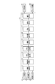
- FIG. 1 is a configuration diagram of a vehicle control device according to the first embodiment.
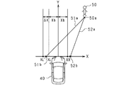
- FIG. 2 is a diagram for explaining a predicted course of a passer-by and a process for correcting the restriction value to a large value (a process for expanding the determination area width) in the first embodiment.
- FIG. 3 is a diagram illustrating a case where the enlargement process in the first embodiment is terminated.
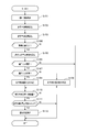
- FIG. 4 is a flowchart showing processing executed by the vehicle control device in the first embodiment.
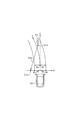
- FIG. 5 is a diagram for explaining a predicted course of a passer-by and a process for correcting the restriction value to a large value (a process for expanding the determination area width) in the second embodiment.
- the vehicle control device is mounted on a vehicle (host vehicle) and detects a target existing around the front of the host vehicle in the traveling direction. And a vehicle control apparatus performs control for avoiding the collision with the detected target and the own vehicle, or reducing a collision damage.
- the vehicle control device functions as a PCS system.
- FIG. 1 is a configuration diagram of a vehicle control device according to the present embodiment.
- a driving assistance ECU 10 that is a vehicle control device according to the present embodiment is a computer that includes a CPU, a memory (for example, ROM or RAM), an I / O, and the like.
- the driving assistance ECU 10 includes a target recognition unit 11, a target information acquisition unit 12, a collision prediction time calculation unit 13, a collision prediction position calculation unit 14, a crossing determination unit 15, a regulation value setting unit 16, a presence determination unit 17, and an operation determination.
- Each function of the unit 18 and the control processing unit 19 is provided.
- the CPU executes a program installed in, for example, a ROM to realize each function.
- the driving support ECU 10 is connected with a sensor device for inputting various detection information.
- sensor devices to be connected include a radar device 21, an imaging device 22, a vehicle speed sensor 23, and the like.
- the radar device 21 is, for example, a millimeter wave radar that transmits a high frequency signal in the millimeter wave band as an exploration wave.
- the radar device 21 is provided at the front end of the host vehicle.
- the radar apparatus 21 detects the position of the target in the detectable area, with the area extending over a range of a predetermined angle as the target detectable area.
- the radar device 21 transmits a survey wave at a predetermined control period and receives reflected waves by a plurality of antennas.
- the radar device 21 calculates the distance from the target that reflected the exploration wave based on the transmission time of the exploration wave and the reception time of the reflected wave. Further, the frequency of the reflected wave reflected by the target changes due to the Doppler effect.
- the radar device 21 calculates a relative speed with respect to the target reflecting the exploration wave based on the changed frequency. Furthermore, the radar apparatus 21 calculates the azimuth of the target reflecting the exploration wave based on the phase difference of the reflected wave received by the plurality of antennas. If the position and orientation of the target can be calculated, the relative position of the target with respect to the host vehicle can be specified. The radar device 21 transmits a search wave, receives a reflected wave, and calculates a relative position and a relative speed of a target with respect to the host vehicle at predetermined control periods. Then, the radar device 21 transmits the calculated relative position and relative speed per unit time to the driving support ECU 10.
- the imaging device 22 is, for example, a CCD camera, a CMOS image sensor, a near infrared camera, or the like.
- the imaging device 22 is provided at a predetermined height in the center in the vehicle width direction of the host vehicle.
- the imaging device 22 images a region that extends over a range of a predetermined angle toward the front of the vehicle from an overhead viewpoint.
- the imaging device 22 extracts a feature point indicating the presence of the target in the captured image. Specifically, the imaging device 22 extracts edge points based on the luminance information of the captured image, and performs Hough transform on the extracted edge points.
- the imaging device 22 performs imaging and feature point extraction for each control cycle that is the same as or different from that of the radar device 21. Then, the imaging device 22 transmits the feature point extraction result to the driving support ECU 10.
- the vehicle speed sensor 23 is provided on a rotating shaft that transmits power to the wheels of the host vehicle. The vehicle speed sensor 23 detects the speed of the host vehicle based on the number of rotations of the rotating shaft. Then, the vehicle speed sensor 23 transmits the speed detection result to the driving support ECU 10.
- the own vehicle includes an alarm device 31, a brake device 32, and the like as various safety devices driven by a control command from the driving support ECU 10.
- the alarm device 31 is, for example, a speaker or a display installed in the passenger compartment of the host vehicle.
- the alarm device 31 outputs an alarm sound, an alarm message, or the like based on a control command from the driving assistance ECU 10 to cause a collision with the driver. Inform the danger.
- the brake device 32 is a braking device that brakes the host vehicle.
- the brake device 32 operates based on a control command from the driving support ECU 10. Specifically, the brake device 32 increases the braking force for the driver's braking operation, or performs automatic braking if the driver does not perform the braking operation. That is, the brake device 32 provides the driver with a brake assist function and an automatic brake function.
- the target recognition unit 11 acquires first detection information (position calculation result) from the radar device 21.
- the target recognition unit 11 acquires second detection information (extraction result of feature points) from the imaging device 22.
- the target recognition unit 11 uses the first position information indicated by the position obtained from the first detection information and the second position information indicated by the feature point obtained from the second detection information as follows. Associate with.
- the target recognition unit 11 associates information located in the vicinity as position information of the same target. When the position indicated by the second position information is present in the vicinity of the position indicated by the first position information, there is a high possibility that the target is actually present at the position indicated by the first position information.
- the target recognition unit 11 detects a target detection history (a past detection position) for a target determined to be in the fusion state (a target in which the first position information and the second position information are associated). To determine whether the target is continuously in the fusion state. As a result, the target recognizing unit 11 determines that the target exists at the position when it is continuously determined as the fusion state. Further, the target recognition unit 11 refers to the detection history of the target when the target that is continuously determined to be in the fusion state is in an undetected state, and the target is predetermined at the past detection position. What existed for a period of time.
- the target recognition unit 11 performs pattern matching on the target determined to be in the fusion state. Specifically, the target recognition unit 11 performs pattern matching on the second detection information using pattern data prepared in advance for each type of target that is assumed. Then, the target recognition unit 11 determines whether the determined target is a vehicle or a passer-by based on the pattern matching result, and associates the determination result as the type of the target.
- the concept of a passerby may include a person who rides a bicycle.
- the target information acquisition unit 12 acquires a relative position and a relative speed with respect to the host vehicle based on information (first position information) obtained from the target recognition unit 11, and acquires the acquired relative position and The relative speed is associated as target information (for each target).
- the relative position includes a lateral position that is a relative position of the target with respect to the host vehicle in a lateral direction that is a direction orthogonal to the traveling direction of the host vehicle.
- the relative position includes a vertical position that is a relative position of the target with respect to the host vehicle in a vertical direction that is the traveling direction of the host vehicle.
- the target information acquisition part 12 is the lateral speed which is a relative speed of the target with respect to the own vehicle in the horizontal direction orthogonal to the advancing direction of the own vehicle based on the acquired target information (relative position and relative speed). Is calculated. In addition, the target information acquisition unit 12 calculates a vertical speed that is a relative speed of the target with respect to the host vehicle in the vertical direction that is the traveling direction of the host vehicle, based on the acquired target information.
- the target information acquisition unit 12 is based on the target type (target discrimination result) obtained from the target recognition unit 11 and the horizontal and vertical speeds (relative speeds) of the target. Subdivide the type of mark.
- the vehicle type can be subdivided as follows.
- the target information acquisition unit 12 distinguishes four types of vehicles based on the lateral speed and the vertical speed of the vehicle. Specifically, a preceding vehicle that travels forward in the traveling direction of the host vehicle in the same direction as the host vehicle, and travels in a direction opposite to the host vehicle in the traveling direction forward of the host vehicle (runs in the opposite lane). Differentiate from oncoming vehicles. Further, a distinction is made between a stationary vehicle (stopped vehicle or parked vehicle) that stops in front of the traveling direction of the host vehicle and a passing vehicle that attempts to pass across the front of the traveling direction of the host vehicle.
- the passer type can be subdivided as follows.
- the target information acquisition unit 12 distinguishes four types of passers-by on the basis of the passer's lateral speed and vertical speed. Specifically, a distinction is made between a preceding passerby who walks in front of the host vehicle in the same direction as the host vehicle, and an opposite passerby who walks in front of the host vehicle in the opposite direction of the host vehicle. To do. In addition, a distinction is made between a stationary passerby who stops in front of the traveling direction of the host vehicle and a crossing passer who is trying to cross the front of the traveling direction of the host vehicle.
- the target information acquisition unit 12 distinguishes four types of targets based on the vertical speed of the target. Specifically, a front target moving in the same direction as the host vehicle in the traveling direction ahead of the host vehicle and a counter target moving in the direction opposite to the host vehicle in the traveling direction forward of the host vehicle are distinguished. Further, a distinction is made between a stationary target that is stopped in front of the traveling direction of the host vehicle and a passing target that attempts to pass across the front of the traveling direction of the host vehicle.
- the predicted collision time calculation unit 13 calculates a predicted collision time that is the time until the host vehicle collides with the target. That is, the collision prediction time calculation unit 13 calculates the prediction time until the relative distance (vertical distance) of the target with respect to the host vehicle becomes zero as the collision prediction time. Specifically, the collision prediction time calculation unit 13 calculates the collision prediction time by dividing the relative distance of the target with respect to the host vehicle by the relative speed. In addition, you may use the relative acceleration of the target with respect to the own vehicle for calculation of collision prediction time. In this case, the collision prediction time is calculated on the assumption that the host vehicle and the target are approaching each other by a uniform acceleration linear motion.
- the collision predicted position calculation unit 14 stores the acquired position history of the target over a predetermined period and records it as the position history of the target.
- the predicted collision position calculation unit 14 predicts the movement trajectory of the target based on the recorded position history, and calculates a predicted collision position that is a position predicted to collide with the host vehicle. That is, when the target is a passerby, for example, the predicted collision position calculation unit 14 calculates, as the predicted collision position, a lateral position where the relative distance (vertical distance) between the passerby and the vehicle is zero.
- the collision predicted position calculation unit 14 estimates the movement trajectory of the target based on the past position of the target recorded as the position history and the current position of the target.
- the predicted collision position calculation unit 14 calculates an approximate straight line indicating the predicted course of the target based on the position history of the target, and uses the calculated approximate straight line as a movement locus of the relative position of the target with respect to the host vehicle.
- the movement trajectory of the target is estimated.
- the predicted collision position calculation unit 14 assumes that the target moves along the estimated movement locus (approximate straight line after calculation).
- the predicted collision position calculation unit 14 calculates the position in the horizontal direction when the vertical position (relative distance) of the target with respect to the front end of the host vehicle is zero on the approximate line as the predicted collision position.
- the estimated movement trajectory may be an approximate straight line passing through the current position of the target.
- the crossing determination unit 15 determines whether or not the passerby crosses (moves so as to cross) the forward direction (path) of the own vehicle. Specifically, the crossing determination unit 15 determines whether or not a line segment connecting the current position of the passerby and the predicted collision position (predicted path of the passerby) intersects the path of the host vehicle. As a result, the crossing determination unit 15 determines that the passerby crosses the front of the own vehicle in the traveling direction when the line segment indicating the predicted course of the passerby intersects the course of the own vehicle. In addition, what is necessary is just to calculate the course of the own vehicle used for the said determination as follows, for example.
- the crossing determination unit 15 extracts travel lane markings such as white lines drawn on the road surface in the image captured by the imaging device 22. Then, the crossing determination unit 15 calculates a trajectory of the center position based on the position in the left-right direction of the host vehicle (the position of the lateral end) based on the extracted curvature of the travel lane marking, and calculates the calculated trajectory.
- the course of the host vehicle Note that the predicted course of the passerby intersects with the course of the host vehicle. This means that the current position of the passerby exists on either the left or right side in the lateral direction perpendicular to the traveling direction of the host vehicle, This means that the predicted position exists on the other side. Therefore, the determination as to whether or not the passerby crosses the front in the traveling direction of the host vehicle is based on the above-described positional relationship between the passer's current position and the predicted collision position (whether it is on the left or right side). You may go.
- the restriction value setting unit 16 sets a restriction value that is a value indicating a region width in the horizontal direction orthogonal to the course of the host vehicle.
- the regulation value is a value that defines the width of the determination area (determination area width) for determining whether or not the target exists on the course of the host vehicle. Therefore, the driving assistance ECU 10 determines that the target exists on the course of the host vehicle when the lateral position of the target is within the determination region (within the regulation value) by the presence determination unit 17 described later.
- This regulation value will be described with reference to FIG. In FIG. 2, the lateral direction orthogonal to the traveling direction of the host vehicle 40 is shown as an X axis with the right direction from the central axis of the host vehicle 40 being positive.
- the vertical direction which is the traveling direction of the host vehicle 40
- the Y axis is a straight line passing through the center of the host vehicle 40 (hereinafter referred to as “center axis”) and corresponds to the course of the host vehicle 40.
- the restriction value setting unit 16 sets a restriction value that defines the determination area width in the right direction of the route of the host vehicle 40 based on the right restriction value XR. Further, the restriction value setting unit 16 sets a restriction value that defines the determination region width in the left direction of the route of the host vehicle 40 based on the left restriction value XL. Thereby, the regulation value setting unit 16 sets a determination region as shown in FIG.
- the set determination region has a predetermined lateral width based on the right side regulation value XR in the right direction from the central axis of the host vehicle 40 toward the front in the traveling direction. Moreover, it has the predetermined
- the right side regulation value XR and the left side regulation value XL are values determined in advance for each type of target. Therefore, the regulation value setting unit 16 sets the right regulation value XR and the left regulation value XL based on the type of the target. When there are a plurality of targets, the right limit value XR and the left limit value XL are set for each target.
- the regulation value setting unit 16 When the target is the passer-by 50 and the passer-by 50 crosses the front in the traveling direction of the host vehicle 40, the regulation value setting unit 16 is in the determination region on the side opposite to the side where the passer-by 50 is located. The regulation value is corrected to a large value, and the determination area width is enlarged. That is, the restriction value setting unit 16 corrects the left restriction value XL to a larger value when the passerby 50 is positioned on the right side with respect to the course (Y axis) of the host vehicle 40, and Perform the enlargement process. On the other hand, the restriction value setting unit 16 corrects the right restriction value XR to a larger value when the passerby 50 is positioned on the left side with respect to the course of the host vehicle 40, and performs the right-side determination area width expansion process. .
- the regulation value setting unit 16 performs the following process (determination area width expansion process) on the regulation value.
- the right side regulation value XR and the left side regulation value XL in the normal state are the reference values Xb, respectively.
- the reference value Xb is a predetermined value.
- the restriction value setting unit 16 adds a correction value ⁇ X indicating the enlargement width to the reference value Xb, and corrects the restriction value to a value larger than normal (hereinafter referred to as “normal value”). For convenience, it may be referred to as “enlargement correction”).
- the regulation value setting unit 16 performs the above correction on the regulation value in the determination region on the side opposite to the side where the passerby 50 is located (the side where the predicted collision position exists), and re-uses the regulation value after the correction.
- the determination area is enlarged by setting (enlargement processing is performed).
- FIG. 2 shows a processing example (enlargement of the determination area width) in which the left pass restriction value XL is corrected to a large value when it is determined that the passerby 50 as the target is located on the right side with respect to the central axis of the host vehicle 40. Processing example) is shown.
- the predicted collision position 51b is within the determination region (within the regulation value).
- the predicted course 52a of the passerby 50 does not intersect the course (Y axis) of the host vehicle 40 and the passerby 50 heads from the current position 50a to the predicted collision position 52b, the left limit value XL No enlargement correction is performed.
- the predicted collision position 52b is outside the determination region (outside the regulation value).
- the process determines that the determination area width is enlarged and exists on the course of the host vehicle 40.
- the possibility of being judged is high (it is easy to judge).
- the safety device is easy to operate
- the process of expanding the determination area width is not performed.
- the safety device is less likely to operate and the unnecessary operation of the safety device, which is in a situation where it is activated when not necessary, is suppressed.
- FIG. 3 shows an example in which the above enlargement process (regulation value enlargement correction) is terminated.
- the passer-by 50 continues to cross the front of the own vehicle 40 in the traveling direction, and the predicted course 53 a of the passer-by 50 no longer intersects the course (Y axis) of the own vehicle 40.
- the passerby 50 takes a collision avoidance action. If the enlargement process is continued at this time, the predicted collision position 53b is within the determination region (within the regulation value), and unnecessary operation of the safety device may occur. Therefore, when it is determined that the passerby 50 has crossed the front in the traveling direction of the host vehicle 40 and then it is determined that the person has not crossed again, the restriction value setting unit 16 ends the enlargement process.
- the presence determination unit 17 determines whether the target exists on the course of the host vehicle 40 based on the predicted collision position of the target and the regulation value of the determination area. First, the presence determination unit 17 compares the right side restriction value XR and the left side restriction value XL set by the restriction value setting unit 16 with the predicted collision position of the target. As a result, if the predicted collision position of the target is within the determination region (within the regulation value range), the presence determination unit 17 assumes that the predicted collision position is inside the determination region (inside the regulation value). It is determined that the mark exists on the course of the host vehicle 40.
- the presence determination unit 17 determines that the predicted collision position is outside the determination area (outside the regulation value). Is not present on the course of the host vehicle 40. Specifically, if the target collision prediction position exists in the right direction from the central axis of the host vehicle 40, the presence determination unit 17 determines that the absolute value of the collision prediction position is smaller than the right limit value XR. It is assumed that it is within the range of the right determination region (within the range of the right side regulation value XR).
- the presence determination unit 17 determines the left determination area if the absolute value of the predicted collision position is smaller than the left regulation value XL. Is within the range (within the range of the left limit value XL).
- the operation determination unit 18 determines whether or not to activate the safety device based on a predetermined operation timing and the predicted collision time after calculation. First, the operation determination unit 18 compares the preset operation timing of the safety device with the collision prediction time calculated by the collision prediction time calculation unit 13. Thereby, the operation determination unit 18 determines whether or not the collision prediction time has reached the operation timing (whether or not the collision prediction time is equal to or less than the operation timing). As a result, the operation determination unit 18 determines that the safety device is to be operated when the collision prediction time has reached the operation timing (when the collision prediction time is equal to or less than the operation timing).
- the operation determination unit 18 determines that the safety device is not operated when the predicted collision time has not reached the operation timing (when the predicted collision time is greater than the operation timing). If it is determined that the safety device is to be operated, the operation determination unit 18 transmits a determination result (operation determination signal) to the control processing unit 19 and instructs control of the safety device to be operated.
- the operation timing of the safety device is set in advance for each safety device, such as the alarm device 31 and the brake device 32, for example. Specifically, for example, the alarm device 31 has an operation timing that is earliest than other safety devices.
- the brake device 32 is set with operation timings for each of the brake assist function and the automatic brake function of the brake device 32. Note that these operation timings may be the same value or different values.
- the control processing unit 19 performs operation control of the safety device.
- the control processing unit 19 transmits a control signal to the safety device to be operated based on the determination result received from the operation determination unit 18. This activates the safety device.
- the operation determination unit 18 and the control processing unit 19 cooperate to perform operation control of the safety device.
- a series of processes executed by the driving support ECU 10 according to the present embodiment will be described with reference to FIG.
- the process shown in FIG. 4 is executed for each target existing ahead in the traveling direction of the host vehicle 40 for each predetermined control cycle. This process is also executed for each function of the safety device. Note that the control cycle of this process may be the same as or different from the control cycle of the radar device 21 and the imaging device 22.
- the target recognition unit 11 acquires target detection information (position detection value) (S101).
- the driving support ECU 10 performs the following processing by the target information acquisition unit 12.
- the target information acquisition unit 12 is based on the first detection information (position calculation result) from the radar device 21 and the second detection information (feature point extraction result) from the imaging device 22.
- the relative position (lateral position and vertical position) and relative speed (lateral speed and vertical speed) of the target are calculated.
- the target information acquisition unit 12 performs pattern matching on the target and determines the type based on the result.
- the target information acquisition unit 12 acquires these results as target information.
- the collision prediction time calculation unit 13 calculates a collision prediction time which is a time until the host vehicle 40 collides with the target (S102). At this time, the collision prediction time calculation unit 13 calculates the collision prediction time based on the vertical position and the vertical speed included in the target information. Subsequently, in the driving assistance ECU 10, the predicted collision position calculation unit 14 calculates a predicted collision position that is a position where the target is predicted to collide with the host vehicle 40 (S103). At this time, the predicted collision position calculation unit 14 estimates the movement trajectory of the target based on the past horizontal position of the target recorded as the position history and the current horizontal position included in the target information. The predicted collision position is calculated from the result.
- the driving assistance ECU 10 determines whether the crossing determination unit 15 is the passerby 50 (S104). At this time, the crossing determination unit 15 determines whether the target is the passerby 50 based on the determination result included in the target information. When the target is the passerby 50 (S104: YES), the crossing determination unit 15 calculates the predicted course of the passerby (S105). The predicted course calculated at this time is a line segment connecting the current lateral position of the passerby 50 and the predicted collision position. Then, the crossing determination unit 15 determines whether or not the passerby 50 has crossed the forward direction (route) of the host vehicle 40 (S106).
- the crossing determination unit 15 determines whether or not the predicted path of the passerby 50 crosses the path of the host vehicle 40 by determining whether or not the predicted path of the passerby 50 intersects the path of the host vehicle 40.
- the driving support ECU 10 determines that the regulation value setting unit 16 is as follows. Perform proper processing.
- the regulation value setting unit 16 determines whether the current lateral position of the passerby 50 exists on the right side or the left side of the vehicle 40 from the central axis toward the front in the traveling direction (S107).
- the regulation value setting unit 16 determines that the current lateral position of the passerby 50 exists on the right side (S107: YES), the regulation value setting unit 16 corrects (enlarges and corrects) the left regulation value XL in the determination area to a large value (S108). .
- the reason why the left determination area width enlargement process as described above is performed is that the passerby 50 is moving from the right to the left in the traveling direction of the host vehicle 40 and collides with the vicinity of the left side of the front end of the host vehicle 40. This is because it is expected.
- the regulation value setting unit 16 determines that the current lateral position of the passerby 50 is present on the left side (S107: NO)
- the regulation value setting unit 16 corrects (enlarges and corrects) the right regulation value XR in the determination region to a large value ( S109).
- the reason why the right determination area width enlargement process as described above is performed is that the passerby 50 moves from the left to the right in the traveling direction of the host vehicle 40, and collides with the vicinity of the right side of the front end of the host vehicle 40. This is because it is expected.
- the regulation value setting unit 16 performs the above correction on the regulation value in the judgment area on the side opposite to the side where the passerby 50 is located, and enlarges the judgment area by resetting the regulation value after the correction. To do.
- the driving support ECU 10 does not perform the rightward restriction value XR and the leftward restriction value XL for enlargement correction (determination area width enlargement process), and does the rightward restriction.
- Each of the value XR and the left limit value XL is set as a reference value Xb.
- the predicted collision position may be used instead of the current lateral position of the passerby 50. In this case, the restriction value on the side where the predicted collision position exists may be enlarged and corrected.
- the presence determination unit 17 compares the predicted collision position of the target with the restriction value in the determination area, and determines whether the predicted collision position is within the restriction value range (within the determination area range). Is determined (S110). At this time, when the predicted collision position of the target is within the range of the regulation value, the presence determination unit 17 determines that the target exists on the course of the host vehicle 40, assuming that the predicted collision position is inside the determination region. . On the other hand, if the predicted collision position of the target is outside the range of the regulation value, the presence determination unit 17 determines that the target is not on the course of the host vehicle 40, assuming that the predicted collision position is outside the determination region. .
- the driving support ECU 10 determines whether the calculated predicted collision time is equal to or less than the operation timing. It is determined whether or not (S111). That is, the operation determination unit 18 determines whether or not the predicted collision time has reached the operation timing. At this time, the operation determination unit 18 determines that the safety device is to be operated when the predicted collision time is shorter than the operation timing (the predicted collision time is shorter than the operation timing) and the predicted collision time reaches the operation timing.
- the operation determination unit 18 determines that the safety device is not operated when the collision prediction time is longer than the operation timing (collision prediction time is longer than the operation timing) and the collision prediction time has not reached the operation timing.
- the operation determination unit 18 determines that the collision prediction time is equal to or less than the operation timing (the collision prediction time has reached the operation timing) (S111: YES)
- the driving support ECU 10 determines that the control processing unit 19 And driving assistance is executed (S112). Thereafter, the series of processing is terminated.
- the operation determination unit 18 transmits a determination result (operation determination signal) to the control processing unit 19, and the control processing unit 19 transmits a control signal to the safety device to be operated based on the received determination result. To do.
- the driving support ECU 10 ends the series of processes.
- the driving support ECU 10 also ends the series of processes when the presence determination unit 17 determines that the predicted collision position of the target is not within the regulation value range (outside the regulation value range) (S110: NO).
- the vehicle control device (driving support ECU 10) according to the present embodiment has the following effects due to the above configuration.
- a situation may occur in which the traveling speed of the passerby 50 crossing (moving across) the path of the host vehicle 40 suddenly changes, such as being stopped on the path of the host vehicle 40. In such a case, it is also difficult to avoid a collision caused by a driver's steering operation or the like. Therefore, in the present embodiment, when the passer-by 50 crosses the front in the traveling direction of the host vehicle 40, the regulation value on the side to which the passer-by 50 is to be moved among the left and right specified values that define the determination area width is set. Correction is performed to a large value (enlargement correction) to enlarge the determination area width.
- the vehicle control device According to the present embodiment, there is a high possibility that a passerby 50 who has a high risk of colliding with the host vehicle 40 is determined to be present on the course of the host vehicle 40. (It becomes easy to judge). Thereby, in the vehicle control apparatus which concerns on this embodiment, the non-operation of the safety device which is a condition which does not operate
- the passerby 50 is moving in front of the traveling direction of the host vehicle 40, but when the traveling person 50 is not moving across the course of the host vehicle 40, it is easy to avoid a collision by a driver's steering operation.
- the passerby 50 may take a collision avoidance action. In such a case, if the safety device is operated, the operation becomes an unnecessary operation (a situation in which it operates when not necessary). Therefore, in the present embodiment, when the passerby 50 does not cross the course of the host vehicle 40, the process of enlarging the determination area width (enlargement correction of the regulation value) is not performed.
- the vehicle control device it is less likely that the passerby 50 who has a low risk of colliding with the host vehicle 40 is determined to be present on the course of the host vehicle 40. (It becomes difficult to judge). Thereby, in the vehicle control apparatus which concerns on this embodiment, the unnecessary operation
- the vehicle control device has the same overall configuration as the vehicle control device shown in the first embodiment, and part of the processing is different. Specifically, in this embodiment, the processes of the crossing determination unit 15 and the regulation value setting unit 16 included in the driving support ECU 10 that is the vehicle control device are partially different (part of the processing is added).
- the road on which the vehicle 40 travels includes not only a straight section (straight road) but also a curved section (curved road). Therefore, in the present embodiment, in consideration of the case where the host vehicle 40 is traveling on a road in a curved section (when the course of the host vehicle 40 is a curve), the restriction value setting unit 16 performs an enlargement correction (determination area) (Width expansion processing).
- the crossing determination unit 15 performs the crossing determination process using a center line that is a straight line that passes through the center position based on the position of the lateral end (left and right end) of the host vehicle 40. Is going.
- the host vehicle 40 is traveling on a road that curves in the left direction (curved road in the left direction).
- the current position 50a of the passerby 50 exists on the left side of the center line C
- the predicted collision position 54b also exists on the left side of the center line C.
- the predicted course 54a of the passerby 50 and the course (Y axis) of the host vehicle 40 intersect, but a collision can be avoided by the steering operation in the right direction of the driver.
- collision can be avoided by the passerby 50 moving at a higher speed.
- the regulation value setting unit 16 when the course of the host vehicle 40 is a curve and the relationship between the current position of the passerby 50 and the predicted collision position is as described above, the regulation value Enlargement correction (determination area width enlargement process) is not performed.
- the restriction value setting unit 16 performs enlargement correction of the restriction value on the side where the predicted collision position 54b exists, as in the first embodiment.
- the vehicle control device (driving support ECU 10) according to the present embodiment has an effect similar to that of the first embodiment due to the above configuration.
- the course of the host vehicle 40 is calculated based on the image captured by the imaging device 22, but this is not restrictive.
- the radar device 21 may detect a structure on the road and calculate the course of the host vehicle 40 based on the detection result.
- you may calculate based on the detected value of a yaw rate sensor.
- the course of the host vehicle 40 may be calculated using each of the plurality of detection methods, and an average value of the plurality of calculation results may be used as a final course.
- the predicted course of the passer-by 50 is calculated based on the current position of the passer-by 50 and the predicted collision position.
- the predicted collision position is calculated based on the position history of the passerby 50 recorded over a predetermined period.
- the present invention is not limited to this.
- the relative speed of the passer 50 with respect to the host vehicle 40 may be used.
- the predicted course of the passer 50 may be calculated using the current position of the passer 50 and the current relative speed without using the position history of the passer 50.
- the determination is made as to whether or not the passerby 50 is present on the course of the host vehicle 40 (determination as to whether or not to activate the safety device) based on the predicted collision position. Not limited. In the modified example, when both the current position of the passerby 50 and the predicted collision position are within the range of the regulation value (within the determination region), it is determined that the passerby 50 is on the course of the host vehicle 40.
- the safety device may be activated.
- the restriction value enlargement correction may be executed only when the distance between the lateral end of the host vehicle 40 and the predicted collision position is within a predetermined value.
- the correction value ⁇ X is added to perform restriction value enlargement correction (determination area width enlargement processing). For example, when the relative speed (lateral speed) of the passerby 50 with respect to the host vehicle 40 is large, the calculation error of the collision predicted position becomes large. Under such circumstances, when the passerby 50 stops suddenly, the risk of collision is high. Therefore, in a modified example, the larger the lateral speed of the passerby 50, the larger the correction value ⁇ X may be used when the restriction value is enlarged.
- the restriction value is enlarged and corrected using a different correction value ⁇ X. You may make it reset. In this case, if the restriction value is enlarged and corrected (the determination area width is enlarged) without an upper limit, unnecessary operation of the safety device may occur. Therefore, an upper limit may be set for the expansion range of the regulation value. For example, as an example of setting the upper limit, the width of the detectable region of the radar device 21 may be set to the upper limit of the expansion range.
- the correction value ⁇ X used at the time of the correction correction of the regulation value may be changed for each function of the safety device. For example, if the alarm device 31 is activated, the driver is aware of the danger of a collision and is likely to perform a collision avoidance operation. Therefore, the operation of the brake device 32 at this time may be unnecessary. In such a case, only the enlargement correction of the regulation value corresponding to the alarm device 31 may be performed. Alternatively, the correction value ⁇ X corresponding to the alarm device 31 may be changed to a larger value.
- the configuration in which the vehicle control device of the present disclosure is applied to a vehicle driven by a person who gets on the vehicle has been described.
- the vehicle control device of the present disclosure can be similarly applied to a vehicle that is automatically driven by an ECU or the like, for example.
- the operation determination unit 18 and the control processing unit 19 do not function with respect to the alarm device 31 and the brake assist function of the brake device 32.
- the operation determination unit 18 and the control processing unit 19 may be configured to function with respect to the automatic brake function of the brake device 32.
- the configuration in which the alarm device 31 and the brake device 32 are controlled safety devices has been described, but the controlled safety device is not limited thereto.
- SYMBOLS 10 Driving assistance ECU, 11 ... Target recognition part, 12 ... Target information acquisition part, 13 ... Collision prediction time calculation part, 14 ... Collision prediction position calculation part, 15 ... Crossing determination part, 16 ... Restriction value setting part, 17 ... Presence determination unit, 18 ... Operation determination unit, 19 ... Control processing unit.
Landscapes
- Engineering & Computer Science (AREA)
- Mechanical Engineering (AREA)
- Transportation (AREA)
- Physics & Mathematics (AREA)
- General Physics & Mathematics (AREA)
- Automation & Control Theory (AREA)
- Radar, Positioning & Navigation (AREA)
- Remote Sensing (AREA)
- Chemical & Material Sciences (AREA)
- Combustion & Propulsion (AREA)
- Traffic Control Systems (AREA)
- Control Of Driving Devices And Active Controlling Of Vehicle (AREA)
Abstract
車両制御装置は、自車両に対する通行人の相対位置である現在位置を取得する物標情報取得部12と、現在位置に基づいて、自車両の進行方向における通行人と自車両との距離がゼロとなる位置を、衝突予測位置として算出する衝突予測位置算出部14と、通行人が自車両の進路を横断しているか否かを判定する横断判定部15と、自車両の進行方向に直交する横方向における左右の幅を示す規制値を設定する規制値設定部16と、衝突予測位置と規制値とに基づいて、通行人が自車両の進路上に存在するか否かを判定する存在判定部17と、を備え、規制値設定部16は、通行人が自車両の進路を横断していると判定された場合に、進行方向において、衝突予測位置が存在する左右いずれか一方の側の規制値を、他方の側の規制値よりも大きい値に設定する。
Description
本開示は、自車両の進路上に物標が存在するか否かを判定し、判定結果に基づき車両を制御する車両制御技術に関する。
従来では、自車両の進行方向前方に位置する他車両、通行人、及び道路構造物等の物標と、自車両との衝突被害を軽減又は防止する、プリクラッシュセーフティ(PCS:Pre-Crash Safety)が実現されている。PCSでは、自車両と物標との相対距離と、相対速度又は相対加速度とに基づいて、自車両が物標に衝突までの予測時間である衝突予測時間(TTC:Time to Collision)を算出する。そして、PCSでは、算出した衝突予測時間に基づいて、自車両の運転者に対して警報装置等により接近を報知したり、自車両の制動装置を作動させたりしている。
PCSに関するものとして、特許文献1に記載の車両制御装置がある。特許文献1に記載の車両制御装置では、自車両の予測軌跡に基づいて設定された判定ゾーンの外側に、通行人の最大移動速度に基づく判定ゾーンが設定されている。そして、車両制御装置では、通行人が判定ゾーンの範囲内に存在すれば、自車両と通行人とが衝突する危険性が高いと判定している。
特許文献1に記載の車両制御装置は、通行人の最大移動速度に基づいて判定ゾーンを設定している。そのため、車両制御装置では、通行人の移動が、衝突の危険性の高い移動か、低い移動かに関わらず、自車両と通行人とが衝突する危険性が高いと判定されやすい。その結果、実際には、通行人の移動が、衝突の危険性の低い移動であるにも関わらず、判定ゾーンが大きく設定された場合には、安全装置に不要作動(必要でないときに作動する状況)が生ずる可能性がある。
本開示は、通行人が自車両の進路上に存在するか否かの判定を精度良く行える車両制御装置、及び、車両制御装置が実行する車両制御方法を提供することを目的とする。
本開示の車両制御装置は、自車両の進行方向前方に存在する通行人の、前記自車両に対する相対位置である現在位置を取得する物標情報取得部(12)と、前記現在位置に基づいて、前記自車両の進行方向において、前記通行人と前記自車両との距離がゼロとなる位置を、衝突予測位置として算出する衝突予測位置算出部(14)と、前記通行人が、前記自車両の進路を横断しているか否かを判定する横断判定部(15)と、前記通行人が前記自車両の進路上に存在するか否かを判定するための判定領域において、前記自車両の前記進行方向に直交する横方向の判定領域幅を示す規制値を設定する規制値設定部(16)と、前記衝突予測位置と前記規制値とに基づいて、前記通行人が前記自車両の進路上に存在するか否かを判定する存在判定部(17)と、を備え、前記規制値設定部は、前記通行人が前記自車両の進路を横断していると判定された場合に、前記自車両の進行方向前方において、前記衝突予測位置が存在する左右いずれか一方の側の前記規制値を、他方の側の前記規制値よりも大きい値に補正し、前記判定領域幅を拡大する拡大処理を行う。
自車両の進路を横断(横切るように移動)する通行人は、自車両の正面近傍(進行方向前方の近傍)からその側方へと移動する際に、例えば、自車両の進路上において立ち止まる等、移動速度が急激に変化する状況が起こり得る。このような場合には、運転者の操舵操作等による衝突の回避が困難である。そこで、上記構成では、通行人が自車両の進行方向前方を横断する場合に、判定領域幅を規定する左右の規定値のうち、通行人の移動先となる側の規制値を大きい値に補正(拡大補正)し、判定領域幅を拡大している。そのため、本開示の車両制御装置では、自車両と衝突する危険性の高い通行人に対して、自車両の進路上に存在すると判定される可能性を高く(判定されやすく)することができる。
一方、通行人は自車両の進行方向前方を移動しているが、自車両の進路を横断する移動ではない場合、運転者の操舵操作による衝突の回避は容易である。また、通行人の方が衝突回避行動をとる場合もある。このような場合に、通行人を自車両の進路上に存在すると判定してしまうと、必要以上(過剰)に通行人の存在を判定することになる。そこで、上記構成では、判定領域幅の拡大処理(規制値の拡大補正)の実行を、通行人が自車両の進路を横断する場合に限定している。そのため、本開示の車両制御装置では、自車両の進路上に存在する可能性の低い通行人に対して、自車両の進路上に存在すると判定される可能性を低く(判定されにくく)することができる。
本開示の車両制御装置では、上記のように、判定領域幅の拡大処理(規制値の拡大補正)の実行条件を設定する構成により、通行人が自車両の進路上に存在するか否かの判定精度を向上できる。
以下、各実施形態を図面に基づいて説明する。なお、以下の各実施形態において、互いに同一もしくは均等である部分には、図中、同一符号を付しており、同一符号の部分についてはその説明を援用する。
<第1実施形態>
本実施形態に係る車両制御装置は、車両(自車両)に搭載され、自車両の進行方向前方等の周囲に存在する物標を検知する。そして、車両制御装置は、検知した物標と自車両との衝突を回避、又は、衝突被害を軽減するための制御を行う。このように、本実施形態に係る車両制御装置は、PCSシステムとして機能する。
本実施形態に係る車両制御装置は、車両(自車両)に搭載され、自車両の進行方向前方等の周囲に存在する物標を検知する。そして、車両制御装置は、検知した物標と自車両との衝突を回避、又は、衝突被害を軽減するための制御を行う。このように、本実施形態に係る車両制御装置は、PCSシステムとして機能する。
図1は、本実施形態に係る車両制御装置の構成図である。図1に示すように、本実施形態に係る車両制御装置である運転支援ECU10は、CPU、メモリ(例えばROMやRAM)、I/O等を備えたコンピュータである。運転支援ECU10は、物標認識部11、物標情報取得部12、衝突予測時間算出部13、衝突予測位置算出部14、横断判定部15、規制値設定部16、存在判定部17、作動判定部18、及び制御処理部19の各機能を有している。運転支援ECU10は、CPUが、例えばROMにインストールされているプログラムを実行し、各機能を実現する。
運転支援ECU10には、各種検知情報を入力するセンサ装置が接続されている。接続されるセンサ装置としては、例えば、レーダ装置21、撮像装置22、及び車速センサ23等がある。
レーダ装置21は、例えば、ミリ波帯の高周波信号を探査波として送信するミリ波レーダである。レーダ装置21は、自車両の前端部に設けられている。レーダ装置21は、所定の角度の範囲に亘って広がる領域を、物標を検知可能領域とし、検知可能領域内の物標の位置を検出する。具体的には、レーダ装置21は、所定の制御周期で探査波を送信し、複数のアンテナにより反射波を受信する。そして、レーダ装置21は、探査波の送信時刻と反射波の受信時刻とに基づいて、探査波を反射した物標との距離を算出する。また、物標に反射された反射波の周波数は、ドップラー効果により変化する。よって、レーダ装置21は、変化した周波数に基づいて、探査波を反射した物標との相対速度を算出する。さらに、レーダ装置21は、複数のアンテナが受信した反射波の位相差に基づいて、探査波を反射した物標の方位を算出する。なお、物標の位置及び方位が算出できれば、自車両に対する物標の相対位置を特定できる。レーダ装置21は、所定の制御周期ごとに、探査波の送信、反射波の受信、自車両に対する物標の相対位置及び相対速度の算出を行う。そして、レーダ装置21は、算出した単位時間あたりの相対位置と相対速度とを運転支援ECU10に送信する。
撮像装置22は、例えばCCDカメラ、CMOSイメージセンサ、近赤外線カメラ等である。撮像装置22は、自車両の車幅方向中央の所定の高さに設けられている。撮像装置22は、車両前方へ向けて、所定の角度の範囲に亘って広がる領域を、俯瞰視点から撮像する。撮像装置22は、撮像画像において、物標の存在を示す特徴点を抽出する。具体的には、撮像装置22は、撮像画像の輝度情報に基づいて、エッジ点を抽出し、抽出したエッジ点に対してハフ変換を行う。なお、ハフ変換では、例えば、エッジ点が複数個連続して並ぶ直線上の点や、直線同士が直交する点を、特徴点として抽出する。撮像装置22は、レーダ装置21と同じ若しくは異なる制御周期ごとに、撮像及び特徴点の抽出を行う。そして、撮像装置22は、特徴点の抽出結果を運転支援ECU10へ送信する。車速センサ23は、自車両の車輪に動力を伝達する回転軸に設けられている。車速センサ23は、回転軸の回転数に基づいて、自車両の速度を検出する。そして、車速センサ23は、速度の検出結果を運転支援ECU10へ送信する。
自車両は、運転支援ECU10からの制御指令により駆動する各種安全装置として、警報装置31及びブレーキ装置32等を備えている。
警報装置31は、例えば、自車両の車室内に設置されたスピーカやディスプレイ等である。運転支援ECU10が、物標に衝突する可能性があると判定した場合、警報装置31は、運転支援ECU10からの制御指令に基づいて、警報音や警報メッセージ等を出力して運転者に衝突の危険性を報知する。
ブレーキ装置32は、自車両を制動する制動装置である。運転支援ECU10が、物標に衝突する可能性があると判定した場合、ブレーキ装置32は、運転支援ECU10からの制御指令に基づき作動する。具体的には、ブレーキ装置32は、運転者のブレーキ操作に対する制動力をより強くしたり、運転者がブレーキ操作を行っていなければ自動制動を行ったりする。つまり、ブレーキ装置32は、運転者に対して、ブレーキアシスト機能や自動ブレーキ機能を提供する。
運転支援ECU10が有する機能部について説明する。本実施形態に係る物標認識部11は、レーダ装置21から第1検知情報(位置の算出結果)を取得する。また、物標認識部11は、撮像装置22から第2検知情報(特徴点の抽出結果)を取得する。そして、物標認識部11は、第1検知情報から得られた位置で示される第1位置情報と、第2検知情報から得られた特徴点で示される第2位置情報とを、次のように対応付ける。物標認識部11は、近傍に位置する情報同士を、同じ物標の位置情報として対応付ける。第1位置情報で示される位置の近傍に、第2位置情報で示される位置が存在する場合には、第1位置情報で示される位置に、実際に物標が存在する可能性が高い。このように、レーダ装置21及び撮像装置22により、物標の位置が精度良く取得できている状態を「フュージョン状態」という。物標認識部11は、フュージョン状態と判定された物標(第1位置情報と第2位置情報とが対応付けられた物標)に対して、その物標の検知履歴(過去の検知位置)を参照し、物標が継続してフュージョン状態か否かを判定する。その結果、物標認識部11は、継続してフュージョン状態と判定された場合、その位置に物標が存在していると決定する。また、物標認識部11は、継続してフュージョン状態と判定された物標が、未検知の状態となった場合、その物標の検知履歴を参照し、過去の検知位置に物標が所定の期間存在していたものする。
物標認識部11は、フュージョン状態と判定された物標に対して、パターンマッチングを行う。具体的には、物標認識部11は、想定される物標の種別ごとに予め用意しておいたパターンデータを用いて、第2検知情報に対してパターンマッチングを行う。そして、物標認識部11は、パターンマッチング結果に基づいて、判定した物標が、車両であるか、通行人であるかを判別し、物標の種別として判別結果を対応付ける。なお、本実施形態では、通行人という概念に、自転車に乗る人を含んでもよい。
本実施形態に係る物標情報取得部12は、物標認識部11から得られた情報(第1位置情報)に基づいて、自車両に対する相対位置及び相対速度を取得し、取得した相対位置及び相対速度を、物標情報として(物標ごとに)対応付ける。この相対位置は、自車両の進行方向に直交する方向である横方向における、自車両に対する物標の相対位置である横位置を含む。また、相対位置は、自車両の進行方向である縦方向における、自車両に対する物標の相対位置である縦位置を含む。そして、物標情報取得部12は、取得した物標情報(相対位置及び相対速度)に基づいて、自車両の進行方向に直交する横方向における、自車両に対する物標の相対速度である横速度を算出する。また、物標情報取得部12は、取得した物標情報に基づいて、自車両の進行方向である縦方向における、自車両に対する物標の相対速度である縦速度を算出する。
さらに、物標情報取得部12は、物標認識部11から得られた物標の種別(物標の判別結果)と、物標の横速度及び縦速度(相対速度)とに基づいて、物標の種別を細分化する。
例えば、物標の種別が車両と判別された場合には、車両の種別を次のように細分化できる。物標情報取得部12は、車両の横速度と縦速度とに基づいて、車両の種別を4つに区別する。具体的には、自車両の進行方向前方を自車両と同方向に向かって走行する先行車両と、自車両の進行方向前方を自車両と反対方向に向かって走行する(対向車線を走行する)対向車両とに区別する。また、自車両の進行方向前方で立ち止まっている静止車両(停止車両又は駐車車両)と、自車両の進行方向前方を横切って通過しようとする通過車両とに区別する。
また、物標の種別が通行人と判別された場合には、通行人の種別を次のように細分化できる。物標情報取得部12は、通行人の横速度と縦速度とに基づいて、通行人の種別を4つに区別する。具体的には、自車両の進行方向前方を自車両と同方向に向かって歩行する先行通行人と、自車両の進行方向前方を自車両と反対方向に向かって歩行する対向通行人とに区別する。また、自車両の進行方向前方で立ち止まっている静止通行人と、自車両の進行方向前方を横切ろうとしている(横断しようとしている)横断通行人とに区別する。
なお、第1検知情報のみによって検出された物標については、次のように細分化できる。物標情報取得部12は、物標の縦速度に基づいて、物標の種別を4つに区別する。具体的には、自車両の進行方向前方を自車両と同方向に向かって移動する先行物標と、自車両の進行方向前方を自車両と反対方向に移動する対向物標とに区別する。また、自車両の進行方向前方で停止している静止物標と、自車両の進行方向前方を横切って通過しようとする通過物標とに区別する。
本実施形態に係る衝突予測時間算出部13は、自車両が物標に衝突するまでの時間である衝突予測時間を算出する。つまり、衝突予測時間算出部13は、自車両に対する物標の相対距離(縦方向の距離)がゼロになるまでの予測時間を、衝突予測時間として算出する。具体的には、衝突予測時間算出部13は、自車両に対する物標の相対距離を相対速度で除算することにより、衝突予測時間を算出する。なお、衝突予測時間の算出には、自車両に対する物標の相対加速度を用いてもよい。この場合には、等加速度直線運動により、自車両と物標とが接近すると仮定して、衝突予測時間を算出する。
本実施形態に係る衝突予測位置算出部14は、取得された物標の位置履歴を所定の期間に亘って記憶し、物標の位置履歴として記録する。衝突予測位置算出部14は、記録した位置履歴に基づいて、物標の移動軌跡を予測し、自車両に衝突すると予測される位置である衝突予測位置を算出する。つまり、衝突予測位置算出部14は、例えば物標が通行人であった場合、通行人と自車両との相対距離(縦方向の距離)がゼロとなる横位置を衝突予測位置として算出する。具体的には、衝突予測位置算出部14は、位置履歴として記録した物標の過去の位置と、物標の現在の位置とに基づいて、物標の移動軌跡を推定する。このとき、衝突予測位置算出部14は、物標の位置履歴に基づいて、物標の予測進路を示す近似直線を算出し、算出した近似直線を、自車両に対する物標の相対位置の移動軌跡とすることで、物標の移動軌跡を推定する。そして、衝突予測位置算出部14は、推定した移動軌跡(算出後の近似直線)に沿って物標が移動すると仮定する。これにより、衝突予測位置算出部14は、近似直線上において、自車両の前端部に対する物標の縦位置(相対距離)がゼロとなる場合の横方向の位置を、衝突予測位置として算出する。なお、推定する移動軌跡は、物標の現在の位置を通る近似直線としてもよい。
本実施形態に係る横断判定部15は、通行人が自車両の進行方向前方(進路)を横断している(横切るように移動している)か否かを判定する。具体的には、横断判定部15は、通行人の現在の位置と衝突予測位置とを結ぶ線分(通行人の予測進路)が、自車両の進路と交差するか否かを判定する。その結果、横断判定部15は、通行人の予測進路を示す線分が自車両の進路と交差している場合、通行人が自車両の進行方向前方を横断していると判定する。なお、上記判定に用いる自車両の進路は、例えば次のように算出すればよい。横断判定部15は、撮像装置22による撮像画像において、路面に描かれた白線等の走行区画線を抽出する。そして、横断判定部15は、抽出した走行区画線の曲率に基づいて、自車両の左右方向における位置(横方向端部の位置)を基準とする中心位置の軌跡を算出し、算出した軌跡を自車両の進路とする。なお、通行人の予測進路が自車両の進路と交差するということは、通行人の現在の位置が、自車両の進行方向に直交する横方向における左右のいずれか一方の側に存在し、衝突予測位置が、他方の側に存在することを意味している。よって、通行人が自車両の進行方向前方を横断しているか否かの判定は、通行人の現在の位置と衝突予測位置との上記位置関係(左右いずれの側に存在するか)を条件に行ってもよい。
本実施形態に係る規制値設定部16は、自車両の進路に直交する横方向の領域幅を示す値である規制値を設定する。規制値は、物標が自車両の進路上に存在するか否かを判定するための判定領域の幅(判定領域幅)を規定する値である。よって、運転支援ECU10は、後述する存在判定部17によって、物標の横位置が判定領域内(規制値内)の場合、その物標が自車両の進路上に存在すると判定する。この規制値について、図2を参照し説明する。図2では、自車両40の進行方向に直交する横方向を、自車両40の中心軸から右方向を正とするX軸として示している。また、自車両40の進行方向である縦方向を、自車両40の前方方向を正とするY軸として示している。すなわち、Y軸は自車両40の中心を通る直線(以下「中心軸」という)であり、自車両40の進路に相当する。規制値設定部16は、右方規制値XRに基づいて、自車両40の進路の右方向における判定領域幅を規定する規制値を設定する。また、規制値設定部16は、左方規制値XLに基づいて、自車両40の進路の左方向における判定領域幅を規定する規制値を設定する。これにより、規制値設定部16は、右方規制値XR及び左方規制値XLに基づいて、図2に示すような判定領域を、自車両40の進行方向前方に設定する。その結果、設定された判定領域は、自車両40の中心軸から進行方向前方に向かって右方向に、右方規制値XRに基づく所定の横幅を有する。また、進行方向前方に向かって左方向に、左方規制値XLに基づく所定の横幅を有する。なお、右方規制値XR及び左方規制値XLは、物標の種別ごとに予め定めておいた値である。よって、規制値設定部16は、物標の種別に基づいて、右方規制値XR及び左方規制値XLを設定する。物標が複数存在する場合には、右方規制値XR及び左方規制値XLは、物標ごとに設定される。
規制値設定部16は、物標が通行人50であり、その通行人50が自車両40の進行方向前方を横断している場合に、通行人50が位置する側の反対側の判定領域の規制値を大きい値に補正し、判定領域幅の拡大処理を行う。すなわち、規制値設定部16は、通行人50が自車両40の進路(Y軸)に対して右側に位置する場合に、左方規制値XLを大きい値に補正し、左側の判定領域幅の拡大処理を行う。一方、規制値設定部16は、通行人50が自車両40の進路に対して左側に位置する場合に、右方規制値XRを大きい値に補正し、右側の判定領域幅の拡大処理を行う。
具体的には、規制値設定部16は、規制値に対して、次のような処理(判定領域幅の拡大処理)を行う。まず、通常時の右方規制値XR及び左方規制値XLは、それぞれ基準値Xbであるとする。なお、基準値Xbは、予め定められた値である。規制値設定部16は、規制値を補正し、判定領域幅を拡大する場合、基準値Xbに拡大幅を示す補正値ΔXを加算し、規制値を通常時よりも大きい値に補正する(以下、便宜上「拡大補正」という場合がある)。このとき、規制値設定部16は、通行人50が位置する側の反対側(衝突予測位置が存在する側)の判定領域の規制値に対して上記補正を行い、補正後の規制値を再設定することで判定領域を拡大する(拡大処理を行う)。図2には、物標である通行人50が自車両40の中心軸に対して右側に位置すると判定された場合の左方規制値XLを大きい値に補正する処理例(判定領域幅の拡大処理例)が示されている。このような場合には、規制値設定部16は、左方規制値XLに補正値ΔXを加算することで補正後の左方規制値XL´を算出し(XL´=XL+ΔX)、新たな規制値として再設定する。なおこのとき、右方規制値XRについては拡大補正を行わない。そのため、右方規制値XRは基準値Xbと等しい値となる。図2に示すように、通行人50の予測進路51aが自車両40の進路(Y軸)と交差し、通行人50が、現在の位置50aから衝突予測位置51bへと向かう場合には、左方規制値XLの拡大補正(左側の判定領域幅の拡大処理)が行われる。その結果、衝突予測位置51bが判定領域内(規制値内)となる。一方、通行人50の予測進路52aが自車両40の進路(Y軸)と交差せず、通行人50が、現在の位置50aから衝突予測位置52bへと向かう場合には、左方規制値XLの拡大補正は行われない。その結果、衝突予測位置52bが判定領域外(規制値外)となる。
すなわち、自車両40の進行方向前方を横断しており、自車両40との衝突の危険性が高い通行人50については、判定領域幅の拡大処理を行い、自車両40の進路上に存在すると判定される可能性を高く(判定されやすく)している。これにより、本実施形態に係る車両制御装置(運転支援ECU10)では、安全装置が作動しやすく、必要なときに作動しない状況である安全装置の不作動を抑制している。一方、自車両40の近傍に位置するが、自車両40の進行方向前方を横断せず、自車両40との衝突の危険性が低い通行人50については、判定領域幅の拡大処理を行わず、自車両40の進路上に存在すると判定される可能性を低く(判定されにくく)している。これにより、本実施形態に係る車両制御装置(運転支援ECU10)では、安全装置が作動しにくく、必要でないときに作動する状況である安全装置の不要作動を抑制している。
図3には、上記拡大処理(規制値の拡大補正)を終了する場合の例が示されている。図3に示すように、例えば、通行人50が自車両40の進行方向前方の横断を継続し、通行人50の予測進路53aが自車両40の進路(Y軸)と交差しなくなったとする。このような場合には、運転者の操舵操作等により、自車両40と通行人50との衝突の回避は容易である。また、通行人50の方が衝突回避行動をとることも考えられる。このときに上記拡大処理を継続して行った場合には、衝突予測位置53bが判定領域内(規制値内)となり、安全装置の不要作動が生ずる可能性がある。そこで、通行人50が自車両40の進行方向前方を横断していると判定されてから、再び横断していないと判定された場合、規制値設定部16は、上記拡大処理を終了する。
本実施形態に係る存在判定部17は、物標の衝突予測位置と、判定領域の規制値とに基づいて、物標が自車両40の進路上に存在するか否かを判定する。存在判定部17は、まず、規制値設定部16が設定した右方規制値XR及び左方規制値XLと、物標の衝突予測位置とを比較する。その結果、存在判定部17は、物標の衝突予測位置が判定領域の範囲内(規制値の範囲内)の場合、衝突予測位置が判定領域の内側(規制値の内側)であるとして、物標が自車両40の進路上に存在すると判定する。一方、存在判定部17は、物標の衝突予測位置が判定領域の範囲外(規制値の範囲外)の場合、衝突予測位置が判定領域の外側(規制値の外側)であるとして、物標が自車両40の進路上に存在しないと判定する。具体的には、存在判定部17は、物標の衝突予測位置が、自車両40の中心軸から右方向に存在する場合、衝突予測位置の絶対値が右方規制値XRよりも小さければ、右側判定領域の範囲内(右方規制値XRの範囲内)であるとする。一方、存在判定部17は、物標の衝突予測位置が、自車両40の中心軸から左方向に存在する場合、衝突予測位置の絶対値が左方規制値XLよりも小さければ、左側判定領域の範囲内(左方規制値XLの範囲内)であるとする。
本実施形態に係る作動判定部18は、所定の作動タイミングと、算出後の衝突予測時間とに基づいて、安全装置を作動させるか否かを判定する。作動判定部18は、まず、予め設定されている安全装置の作動タイミングと、衝突予測時間算出部13が算出した衝突予測時間とを比較する。これにより、作動判定部18は、衝突予測時間が作動タイミングに達したか否か(衝突予測時間が作動タイミング以下か否か)を判定する。その結果、作動判定部18は、衝突予測時間が作動タイミングに達した場合(衝突予測時間が作動タイミング以下の場合)に、安全装置を作動させると判定する。一方、作動判定部18は、衝突予測時間が作動タイミングに達していない場合(衝突予測時間が作動タイミングより大きい場合)に、安全装置を作動させないと判定する。作動判定部18は、安全装置を作動させると判定した場合、判定結果(作動判定信号)を制御処理部19へと送信し、作動対象の安全装置の制御を指示する。なお、安全装置の作動タイミングは、例えば、警報装置31やブレーキ装置32等のように、安全装置ごとに予め設定されている。具体的には、例えば警報装置31には、他の安全装置より最も早い作動タイミングが設定されている。これは、警報装置31からの報知により、運転者が衝突の可能性に気づき、ブレーキペダルを踏み込めば、運転支援ECU10がブレーキ装置32へ制御指令を行うことなく衝突を回避できるためである。また、ブレーキ装置32には、当該ブレーキ装置32が有するブレーキアシスト機能と自動ブレーキ機能とのそれぞれに対して、作動タイミングが設定されている。なお、これらの作動タイミングについては、同じ値であってもよく、異なる値であってもよい。
本実施形態に係る制御処理部19は、安全装置の作動制御を行う。制御処理部19は、作動判定部18から受信した判定結果に基づいて、作動対象の安全装置に制御信号を送信する。これにより、安全装置が作動する。このように、運転支援ECU10では、作動判定部18と制御処理部19とが協働して、安全装置の作動制御を行っている。
本実施形態に係る運転支援ECU10が実行する一連の処理について、図4を用いて説明する。図4に示す処理は、所定の制御周期ごとに、自車両40の進行方向前方に存在する物標それぞれに対して実行される。また、本処理は、安全装置の機能ごとそれぞれに対しても実行される。なお、本処理の制御周期は、レーダ装置21及び撮像装置22の制御周期と同じであってもよく、異なっていてもよい。
まず、運転支援ECU10は、物標認識部11が、物標の検知情報(位置の検出値)を取得する(S101)。このとき、運転支援ECU10は、物標情報取得部12により、次のような処理が行われる。物標情報取得部12は、レーダ装置21からの第1検知情報(位置の算出結果)と撮像装置22からの第2検知情報(特徴点の抽出結果)とに基づいて、自車両40に対する物標の相対位置(横位置及び縦位置)及び相対速度(横速度及び縦速度)を算出する。また、物標情報取得部12は、物標に対してパターンマッチングを行い、その結果に基づき種別を判別する。物標情報取得部12は、これらの結果を物標情報として取得する。続いて、運転支援ECU10は、衝突予測時間算出部13が、自車両40が物標に衝突するまでの時間である衝突予測時間を算出する(S102)。このとき、衝突予測時間算出部13は、物標情報に含まれる縦位置及び縦速度に基づいて、衝突予測時間を算出する。続いて、運転支援ECU10は、衝突予測位置算出部14が、物標が自車両40に衝突すると予測される位置である衝突予測位置を算出する(S103)。このとき、衝突予測位置算出部14は、位置履歴として記録した物標の過去の横位置と、物標情報に含まれる現在の横位置とに基づいて、物標の移動軌跡を推定し、推定結果から衝突予測位置を算出する。続いて、運転支援ECU10は、横断判定部15が、物標が通行人50か否かを判定する(S104)。このとき、横断判定部15は、物標情報に含まれる判別結果に基づいて、物標が通行人50か否かを判定する。横断判定部15は、物標が通行人50の場合(S104:YES)、その通行人50の予測進路を算出する(S105)。なお、このとき算出される予測進路とは、通行人50の現在の横位置と衝突予測位置とを結ぶ線分である。そして、横断判定部15は、通行人50が自車両40の進行方向前方(進路)を横断しているか否かを判定する(S106)。このとき、横断判定部15は、通行人50の予測進路が、自車両40の進路と交差するか否かを判定することで、横断しているか否かを判定する。その結果、運転支援ECU10は、横断判定部15が、通行人50が自車両40の進行方向前方を横断していると判定した場合(S106:YES)、規制値設定部16が、次のような処理を行う。規制値設定部16は、通行人50の現在の横位置が、自車両40の中心軸から進行方向前方に向かって右側に存在するか、左側に存在するかを判定する(S107)。規制値設定部16は、通行人50の現在の横位置が右側に存在すると判定した場合(S107:YES)、判定領域の左方規制値XLを大きい値に補正(拡大補正)する(S108)。上記のような左側の判定領域幅の拡大処理を行う理由は、通行人50が自車両40の進行方向前方を右から左へと移動しており、自車両40の前端部左側近傍への衝突が予想されるからである。一方、規制値設定部16は、通行人50の現在の横位置が左側に存在すると判定した場合(S107:NO)、判定領域の右方規制値XRを大きい値に補正(拡大補正)する(S109)。上記のような右側の判定領域幅の拡大処理を行う理由は、通行人50が自車両40の進行方向前方を左から右へと移動しており、自車両40の前端部右側近傍への衝突が予想されるからである。このように、規制値設定部16は、通行人50が位置する側の反対側の判定領域の規制値に対して上記補正を行い、補正後の規制値を再設定することで判定領域を拡大する。
なお、運転支援ECU10は、物標が通行人50でない場合(S104:NO)、右方規制値XR及び左方規制値XLの拡大補正(判定領域幅の拡大処理)を行わず、右方規制値XR及び左方規制値XLそれぞれを基準値Xbとする。また、通行人50が自車両40の進行方向前方を横断していないと判定した場合(S106:NO)も同様である。なお、S107の判定処理では、通行人50の現在の横位置の代わりに衝突予測位置を用いてもよい。この場合には、衝突予測位置が存在する側の規制値を拡大補正すればよい。
続いて、運転支援ECU10は、存在判定部17が、物標の衝突予測位置と判定領域の規制値とを比較し、衝突予測位置が規制値の範囲内(判定領域の範囲内)か否かを判定する(S110)。このとき、存在判定部17は、物標の衝突予測位置が規制値の範囲内の場合、衝突予測位置が判定領域の内側であるとして、物標が自車両40の進路上に存在すると判定する。一方、存在判定部17は、物標の衝突予測位置が規制値の範囲外の場合、衝突予測位置が判定領域の外側であるとして、物標が自車両40の進路上に存在しないと判定する。運転支援ECU10は、存在判定部17が、物標の衝突予測位置が規制値の範囲内と判定した場合(S110:YES)、作動判定部18が、算出後の衝突予測時間が作動タイミング以下か否かを判定する(S111)。すなわち、作動判定部18は、衝突予測時間が作動タイミングに達したか否かを判定する。このとき、作動判定部18は、衝突予測時間が作動タイミング以下で(衝突予測時間が作動タイミングより短く)、衝突予測時間が作動タイミングに達した場合、安全装置を作動させると判定する。一方、作動判定部18は、衝突予測時間が作動タイミングより大きく(衝突予測時間が作動タイミングより長く)、衝突予測時間が作動タイミングに達していない場合、安全装置を作動させないと判定する。その結果、運転支援ECU10は、作動判定部18が、衝突予測時間が作動タイミング以下(衝突予測時間が作動タイミングに達した)と判定した場合(S111:YES)、制御処理部19が、安全装置を作動させ、運転支援を実行する(S112)。その後、一連の処理を終了する。このとき、作動判定部18は、判定結果(作動判定信号)を制御処理部19へと送信し、制御処理部19は、受信した判定結果に基づいて、作動対象の安全装置に制御信号を送信する。これにより、安全装置が作動する。一方、運転支援ECU10は、作動判定部18が、衝突予測時間が作動タイミングより大きい(衝突予測時間が作動タイミングに達していない)と判定した場合(S111:NO)、一連の処理を終了する。また、運転支援ECU10は、存在判定部17が、物標の衝突予測位置が規制値の範囲内でない(規制値の範囲外)と判定した場合(S110:NO)も一連の処理を終了する。
本実施形態に係る車両制御装置(運転支援ECU10)は、上記構成により、以下の効果を奏する。
・自車両40の進路を横断(横切るように移動する)通行人50は、自車両40の進路上において立ち止まる等、移動速度が急激に変化する状況が起こり得る。このような場合には、運転者の操舵操作等による衝突の回避も困難である。そこで、本実施形態では、通行人50が自車両40の進行方向前方を横断する場合に、判定領域幅を規定する左右の規定値のうち、通行人50の移動先となる側の規制値を大きい値に補正(拡大補正)し、判定領域幅を拡大している。そのため、本実施形態に係る車両制御装置では、自車両40との衝突する危険性の高い通行人50に対して、自車両40の進路上に存在していると判定される可能性が高くなる(判定されやすくなる)。これにより、本実施形態に係る車両制御装置では、危険を回避するのに必要なときに作動しない状況である安全装置の不作動を抑制できる。
・通行人50は自車両40の進行方向前方を移動しているが、自車両40の進路を横断する移動ではない場合、運転者の操舵操作による衝突の回避は容易である。また、通行人50が衝突回避行動をとる場合もある。このような場合に、安全装置を作動させれば、その作動は不要作動(必要でないときに作動する状況)となる。そこで、本実施形態では、通行人50が自車両40の進路を横断しない場合、判定領域幅の拡大処理(規制値の拡大補正)を行わない。そのため、本実施形態に係る車両制御装置では、自車両40との衝突する危険性の低い通行人50に対して、自車両40の進路上に存在していると判定される可能性が低くなる(判定されにくくなる)。これにより、本実施形態に係る車両制御装置では、安全装置の不要作動を抑制できる。
<第2実施形態>
本実施形態に係る車両制御装置は、第1実施形態に示した車両制御装置と全体構成が共通しており、処理の一部が異なっている。具体的には、本実施形態では、車両制御装置である運転支援ECU10が有する横断判定部15及び規制値設定部16の処理が一部異なる(処理が一部追加されている)。例えば、自車両40が走行する道路には、直線区間(直線路)だけでなく、曲線区間(カーブ路)もある。そこで、本実施形態では、自車両40が曲線区間の道路を走行している場合(自車両40の進路が曲線の場合)を考慮し、規制値設定部16が規制値の拡大補正(判定領域幅の拡大処理)を行う。その中で、本実施形態では、横断判定部15が、自車両40の横方向端部(左右端部)の位置を基準とする中心位置を通る直線である中心線を用いて横断判定処理を行っている。
本実施形態に係る車両制御装置は、第1実施形態に示した車両制御装置と全体構成が共通しており、処理の一部が異なっている。具体的には、本実施形態では、車両制御装置である運転支援ECU10が有する横断判定部15及び規制値設定部16の処理が一部異なる(処理が一部追加されている)。例えば、自車両40が走行する道路には、直線区間(直線路)だけでなく、曲線区間(カーブ路)もある。そこで、本実施形態では、自車両40が曲線区間の道路を走行している場合(自車両40の進路が曲線の場合)を考慮し、規制値設定部16が規制値の拡大補正(判定領域幅の拡大処理)を行う。その中で、本実施形態では、横断判定部15が、自車両40の横方向端部(左右端部)の位置を基準とする中心位置を通る直線である中心線を用いて横断判定処理を行っている。
図5に示すように、例えば、自車両40は左方向にカーブする道路(左方向のカーブ路)を走行しているとする。このとき、通行人50の現在の位置50aは、中心線Cの左側に存在し、衝突予測位置54bも、中心線Cの左側に存在しているとする。このような場合には、通行人50の予測進路54aと自車両40の進路(Y軸)とは交差するが、運転者の右方向への操舵操作により、衝突を回避できる。また、通行人50が速度を上げて移動することにより、衝突を回避できる。このときに、左方規制値XLの拡大補正(左側の判定領域幅の拡大処理)を行った場合には、衝突予測位置54bが判定領域内(規制値内)となり、安全装置の不要作動が生ずる可能性がある。そのため、本実施形態に係る規制値設定部16では、自車両40の進路が曲線であり、かつ、通行人50の現在の位置と衝突予測位置との関係が上記のような場合、規制値の拡大補正(判定領域幅の拡大処理)を行わない。
一方、通行人50の現在の位置50aは、中心線Cの右側に存在しているとする。さらに、衝突予測位置54bが、自車両40の進路(Y軸)の左側に存在するように、通行人50は自車両40の進行方向前方を横断しているとする。このような場合には、左右いずれの方向に操舵操作を行えば衝突を回避できるのかを、運転者が判断することは困難である。そのため、本実施形態に係る規制値設定部16では、上記のような場合、第1実施形態と同様に、衝突予測位置54bが存在する側の規制値の拡大補正を行う。
本実施形態に係る車両制御装置(運転支援ECU10)は、上記構成により、第1実施形態に準ずる効果を奏する。
<変形例>
・上記実施形態では、自車両40の進路を、撮像装置22による撮像画像に基づき算出する構成としたが、この限りでない。変形例では、レーダ装置21で道路上の構造物を検知し、その検知結果に基づいて、自車両40の進路を算出するようにしてもよい。また、自車両40がヨーレートセンサを備えている場合には、ヨーレートセンサの検出値に基づき算出してもよい。また、上記複数の検知方法それぞれを用いて自車両40の進路を算出し、複数の算出結果の平均値を、最終的な進路としてもよい。
・上記実施形態では、自車両40の進路を、撮像装置22による撮像画像に基づき算出する構成としたが、この限りでない。変形例では、レーダ装置21で道路上の構造物を検知し、その検知結果に基づいて、自車両40の進路を算出するようにしてもよい。また、自車両40がヨーレートセンサを備えている場合には、ヨーレートセンサの検出値に基づき算出してもよい。また、上記複数の検知方法それぞれを用いて自車両40の進路を算出し、複数の算出結果の平均値を、最終的な進路としてもよい。
・上記実施形態では、通行人50の現在の位置と衝突予測位置とに基づいて、通行人50の予測進路を算出している。またその中で、上記実施形態では、所定の期間に亘って記録しておいた通行人50の位置履歴に基づいて、衝突予測位置を算出する構成としたが、この限りでない。変形例では、通行人50の予測進路を算出する際に、自車両40に対する通行人50の相対速度を用いるようにしてもよい。この場合には、通行人50の位置履歴を用いず、通行人50の現在の位置と、現在の相対速度とを用いて、通行人50の予測進路を算出するようにしてもよい。
・上記実施形態では、通行人50が自車両40の進路上に存在するか否かの判定(安全装置を作動させるか否かの判定)を、衝突予測位置に基づき行う構成としたが、この限りでない。変形例では、通行人50の現在の位置と衝突予測位置との両方が、規制値の範囲内(判定領域内)である場合に、通行人50が自車両40の進路上に存在すると判定し、安全装置を作動させるようにしてもよい。
・上記実施形態では、物標が通行人50であり、かつ、通行人50が自車両40の進路を横断している場合を、規制値の拡大補正(判定領域幅の拡大処理)の実行条件とする構成としたが、この限りでない。変形例では、規制値の拡大補正の実行を、自車両40の横方向端部と衝突予測位置との距離が、所定値以内の場合に限定してもよい。これにより、上記変形例では、安全装置の不要作動をさらに抑制できる。
・上記実施形態では、補正値ΔXを加算することで、規制値の拡大補正(判定領域幅の拡大処理)を行っている。例えば、自車両40に対する通行人50の相対速度(横速度)が大きい場合には、衝突予測位置の算出誤差が大きくなる。また、このような状況下では、通行人50が急に停止した場合、衝突の危険性が高い。そのため、変形例では、通行人50の横速度が大きいほど、規制値の拡大補正時に、より大きい値の補正値ΔXを用いるようにしてもよい。
・また、衝突予測時間が短いほど、自車両40と通行人50との衝突の危険性は高い。同様に、相対速度や車速が大きいほど、自車両40と通行人50との衝突の危険性は高い。そのため、変形例では、衝突予測時間、相対速度、車速(車速センサ23で検出可能な自車両40の速度)等に基づいて、異なる補正値ΔXを用いて規制値を拡大補正し、規制値を再設定するようにしてもよい。なお、この場合には、上限なく規制値を拡大補正(判定領域幅を拡大)してしまうと、安全装置の不要作動が生ずる可能性がある。そのため、規制値の拡大範囲には上限を設定するようにしてもよい。例えば、上限の設定例としては、レーダ装置21の検知可能領域の幅を、拡大範囲の上限に設定する等が挙げられる。
・また、変形例では、規制値の拡大補正時(判定領域幅の拡大処理時)に用いる補正値ΔXを、安全装置の機能ごとに変更するようにしてもよい。例えば、警報装置31を作動させれば、運転者は衝突の危険性に気付いて、衝突回避操作を行う可能性が高い。そのため、このときのブレーキ装置32の作動は不要である場合がある。このような場合には、警報装置31に対応する規制値の拡大補正のみを行うようにしてもよい。または、警報装置31に対応する補正値ΔXを、より大きい値に変更するようにしてもよい。
・上記実施形態では、本開示の車両制御装置を、乗車した人により運転される車両に適用する構成について説明を行ったが、この限りでない。本開示の車両制御装置は、例えば、ECU等によって自動運転される車両に対しても同様に適用できる。この場合には、作動判定部18及び制御処理部19は、警報装置31、及び、ブレーキ装置32のブレーキアシスト機能に対して機能しない。作動判定部18及び制御処理部19は、ブレーキ装置32の自動ブレーキ機能に対して機能する構成とすればよい。
・上記実施形態では、警報装置31及びブレーキ装置32を、制御対象の安全装置とする構成について説明を行ったが、制御対象の安全装置はこれに限らない。
10…運転支援ECU、11…物標認識部、12…物標情報取得部、13…衝突予測時間算出部、14…衝突予測位置算出部、15…横断判定部、16…規制値設定部、17…存在判定部、18…作動判定部、19…制御処理部。
Claims (7)
- 自車両の進行方向前方に存在する通行人の、前記自車両に対する相対位置である現在位置を取得する物標情報取得部(12)と、
前記現在位置に基づいて、前記自車両の進行方向において、前記通行人と前記自車両との距離がゼロとなる位置を、衝突予測位置として算出する衝突予測位置算出部(14)と、
前記通行人が前記自車両の進路を横断しているか否かを判定する横断判定部(15)と、
前記通行人が前記自車両の進路上に存在するか否かを判定するための判定領域において、前記自車両の前記進行方向に直交する横方向の判定領域幅を示す規制値を設定する規制値設定部(16)と、
前記衝突予測位置と前記規制値とに基づいて、前記通行人が前記自車両の進路上に存在するか否かを判定する存在判定部(17)と、を備え、
前記規制値設定部は、前記通行人が前記自車両の進路を横断していると判定された場合に、前記自車両の前記進行方向において、前記衝突予測位置が存在する左右いずれか一方の側の前記規制値を、他方の側の前記規制値よりも大きい値に補正し、前記判定領域幅を拡大する拡大処理を行う、車両制御装置。 - 前記横断判定部は、前記拡大処理を行っている場合に、前記横断判定部による前記通行人の横断の判定が終了したことに基づいて、前記拡大処理を終了する、請求項1に記載の車両制御装置。
- 前記横断判定部は、前記自車両の進路と前記通行人の進路とが交差する場合に、前記通行人が横断していると判定する、請求項1又は2に記載の車両制御装置。
- 前記横断判定部は、前記現在位置が、前記自車両の進路に対して左右のいずれか一方の側に存在しており、前記衝突予測位置が、他方の側に存在する場合に、前記通行人が横断していると判定する、請求項1又は2に記載の車両制御装置。
- 前記規制値設定部は、前記通行人が、前記自車両の横方向端部の位置を基準とする中心位置を通る中心線の右側に位置し、且つ、前記自車両の進路に対して左側に移動している場合、又は、前記通行人が、前記中心線の左側に位置し、且つ、前記自車両の進路に対して右側に移動している場合に、前記拡大処理を実行する、請求項1乃至4のいずれか1項に記載の車両制御装置。
- 前記物標情報取得部は、前記自車両の前記進行方向に直交する前記横方向における前記通行人の速度を取得し、
前記規制値設定部は、前記速度が大きいほど、前記拡大処理において、前記規制値をより大きい値に設定する、請求項1乃至5のいずれか1項に記載の車両制御装置。 - 車両制御装置により実行される車両制御方法であって、
前記車両制御装置が、
自車両の進行方向前方に存在する通行人の、前記自車両に対する相対位置である現在位置を取得する物標情報取得ステップと、
前記現在位置に基づいて、前記自車両の進行方向において、前記通行人と前記自車両との距離がゼロとなる位置を、衝突予測位置として算出する衝突予測位置算出ステップと、
前記通行人が前記自車両の進路を横断しているか否かを判定する横断判定ステップと、
前記通行人が前記自車両の進路上に存在するか否かを判定するための判定領域において、前記自車両の前記進行方向に直交する横方向の判定領域幅を示す規制値を設定する規制値設定ステップと、
前記衝突予測位置と前記規制値とに基づいて、前記通行人が前記自車両の進路上に存在するか否かを判定する存在判定ステップと、を実行し、
前記規制値設定ステップでは、前記通行人が前記自車両の進路を横断していると判定された場合に、前記自車両の前記進行方向において、前記衝突予測位置が存在する左右いずれか一方の側の前記規制値を、他方の側の前記規制値よりも大きい値に補正し、前記判定領域幅を拡大する拡大処理を行う、車両制御方法。
Priority Applications (3)
| Application Number | Priority Date | Filing Date | Title |
|---|---|---|---|
| DE112016002348.0T DE112016002348T5 (de) | 2015-05-27 | 2016-05-11 | Fahrzeugsteuervorrichtung und fahrzeugsteuerverfahren |
| US15/576,528 US10723346B2 (en) | 2015-05-27 | 2016-05-11 | Vehicle control apparatus and vehicle control method |
| CN201680029940.0A CN107615356B (zh) | 2015-05-27 | 2016-05-11 | 车辆控制装置以及车辆控制方法 |
Applications Claiming Priority (2)
| Application Number | Priority Date | Filing Date | Title |
|---|---|---|---|
| JP2015-107903 | 2015-05-27 | ||
| JP2015107903A JP6432447B2 (ja) | 2015-05-27 | 2015-05-27 | 車両制御装置、及び車両制御方法 |
Publications (1)
| Publication Number | Publication Date |
|---|---|
| WO2016190103A1 true WO2016190103A1 (ja) | 2016-12-01 |
Family
ID=57393881
Family Applications (1)
| Application Number | Title | Priority Date | Filing Date |
|---|---|---|---|
| PCT/JP2016/063986 Ceased WO2016190103A1 (ja) | 2015-05-27 | 2016-05-11 | 車両制御装置及び車両制御方法 |
Country Status (5)
| Country | Link |
|---|---|
| US (1) | US10723346B2 (ja) |
| JP (1) | JP6432447B2 (ja) |
| CN (1) | CN107615356B (ja) |
| DE (1) | DE112016002348T5 (ja) |
| WO (1) | WO2016190103A1 (ja) |
Cited By (1)
| Publication number | Priority date | Publication date | Assignee | Title |
|---|---|---|---|---|
| JP2023016565A (ja) * | 2021-07-21 | 2023-02-02 | ダイハツ工業株式会社 | 運転支援装置 |
Families Citing this family (18)
| Publication number | Priority date | Publication date | Assignee | Title |
|---|---|---|---|---|
| JP6551382B2 (ja) * | 2016-12-22 | 2019-07-31 | トヨタ自動車株式会社 | 衝突回避支援装置 |
| KR101996418B1 (ko) * | 2016-12-30 | 2019-07-04 | 현대자동차주식회사 | 센서 융합 기반 보행자 탐지 및 보행자 충돌 방지 장치 및 방법 |
| US10611370B2 (en) * | 2017-02-09 | 2020-04-07 | Panasonic Intellectual Property Corporation Of America | Information processing apparatus, information processing method, and non-transitory recording medium |
| CN107591027A (zh) * | 2017-09-21 | 2018-01-16 | 临沂市华夏高科信息有限公司 | 一种非灯控路口避让预警系统 |
| JP2019156180A (ja) * | 2018-03-13 | 2019-09-19 | 本田技研工業株式会社 | 車両制御装置、車両制御方法、およびプログラム |
| CN112292718B (zh) * | 2018-07-12 | 2023-06-06 | 威伯科有限公司 | 用于转向辅助功能的信息、警告和制动请求生成 |
| DE102018120923A1 (de) * | 2018-08-28 | 2020-03-05 | Valeo Schalter Und Sensoren Gmbh | Verfahren zum Unterstützen eines Fahrers eines Fahrzeugs |
| CN109064746A (zh) * | 2018-08-31 | 2018-12-21 | 努比亚技术有限公司 | 一种信息处理方法、终端和计算机可读存储介质 |
| CN113874268A (zh) * | 2019-05-22 | 2021-12-31 | 日立安斯泰莫株式会社 | 车辆控制装置 |
| JP7328863B2 (ja) * | 2019-10-11 | 2023-08-17 | 株式会社デンソー | 制御装置 |
| JP7265971B2 (ja) * | 2019-10-11 | 2023-04-27 | 株式会社デンソー | 制御装置 |
| KR20210153998A (ko) | 2020-06-11 | 2021-12-20 | 현대자동차주식회사 | 차량 및 그 제어방법 |
| CN112440986B (zh) * | 2020-11-30 | 2022-08-09 | 重庆长安汽车股份有限公司 | 一种行车控制方法、行人aeb系统、智能驾驶汽车、控制器及计算机可读存储介质 |
| JP2022134678A (ja) * | 2021-03-03 | 2022-09-15 | 本田技研工業株式会社 | 制御装置、移動体、制御方法及びプログラム |
| CN114999156A (zh) * | 2022-05-27 | 2022-09-02 | 北京汽车研究总院有限公司 | 车前行人横穿场景的自动识别方法、装置、介质和车辆 |
| CN115139999B (zh) * | 2022-06-28 | 2023-09-15 | 重庆长安汽车股份有限公司 | 车辆与行人防撞控制方法及装置、电子设备、存储介质 |
| KR20240125214A (ko) * | 2023-02-10 | 2024-08-19 | 현대자동차주식회사 | 충돌을 회피하기 위한 차량 및 차량의 작동 방법 |
| CN119611353B (zh) * | 2025-01-06 | 2025-10-28 | 一汽解放汽车有限公司 | 车辆紧急制动方法、装置、计算机设备、可读存储介质和程序产品 |
Citations (5)
| Publication number | Priority date | Publication date | Assignee | Title |
|---|---|---|---|---|
| JP2003151096A (ja) * | 2001-11-19 | 2003-05-23 | Honda Motor Co Ltd | 進入警報装置 |
| JP2010093610A (ja) * | 2008-10-09 | 2010-04-22 | Hitachi Automotive Systems Ltd | 自動車の外界認識装置及び外界認識方法 |
| JP2010244474A (ja) * | 2009-04-09 | 2010-10-28 | Hitachi Automotive Systems Ltd | 自動車の外界認識装置 |
| JP2010250501A (ja) * | 2009-04-14 | 2010-11-04 | Hitachi Automotive Systems Ltd | 車両用外界認識装置及びそれを用いた車両システム |
| JP2014067169A (ja) * | 2012-09-25 | 2014-04-17 | Toyota Motor Corp | 衝突予測装置 |
Family Cites Families (8)
| Publication number | Priority date | Publication date | Assignee | Title |
|---|---|---|---|---|
| JP2004268829A (ja) * | 2003-03-11 | 2004-09-30 | Denso Corp | 車両用歩行者衝突危険判定装置 |
| WO2011086661A1 (ja) | 2010-01-12 | 2011-07-21 | トヨタ自動車株式会社 | 衝突位置予測装置 |
| US20130278441A1 (en) * | 2012-04-24 | 2013-10-24 | Zetta Research and Development, LLC - ForC Series | Vehicle proxying |
| JP5729416B2 (ja) * | 2013-04-26 | 2015-06-03 | 株式会社デンソー | 衝突判定装置、および衝突緩和装置 |
| KR101480647B1 (ko) * | 2013-11-15 | 2015-01-09 | 현대자동차주식회사 | 협로 주행을 위한 조향 위험도 판단 시스템 및 그 판단 방법 |
| JP6442904B2 (ja) * | 2014-08-01 | 2018-12-26 | 株式会社デンソー | 運転支援装置 |
| JP6432482B2 (ja) * | 2015-10-14 | 2018-12-05 | 株式会社デンソー | 車両制御装置、車両制御方法 |
| CN106157694B (zh) * | 2016-07-29 | 2019-04-19 | 深圳市元征科技股份有限公司 | 一种交叉路口的行人防碰撞预警方法及装置 |
-
2015
- 2015-05-27 JP JP2015107903A patent/JP6432447B2/ja active Active
-
2016
- 2016-05-11 US US15/576,528 patent/US10723346B2/en active Active
- 2016-05-11 DE DE112016002348.0T patent/DE112016002348T5/de active Pending
- 2016-05-11 WO PCT/JP2016/063986 patent/WO2016190103A1/ja not_active Ceased
- 2016-05-11 CN CN201680029940.0A patent/CN107615356B/zh active Active
Patent Citations (5)
| Publication number | Priority date | Publication date | Assignee | Title |
|---|---|---|---|---|
| JP2003151096A (ja) * | 2001-11-19 | 2003-05-23 | Honda Motor Co Ltd | 進入警報装置 |
| JP2010093610A (ja) * | 2008-10-09 | 2010-04-22 | Hitachi Automotive Systems Ltd | 自動車の外界認識装置及び外界認識方法 |
| JP2010244474A (ja) * | 2009-04-09 | 2010-10-28 | Hitachi Automotive Systems Ltd | 自動車の外界認識装置 |
| JP2010250501A (ja) * | 2009-04-14 | 2010-11-04 | Hitachi Automotive Systems Ltd | 車両用外界認識装置及びそれを用いた車両システム |
| JP2014067169A (ja) * | 2012-09-25 | 2014-04-17 | Toyota Motor Corp | 衝突予測装置 |
Cited By (2)
| Publication number | Priority date | Publication date | Assignee | Title |
|---|---|---|---|---|
| JP2023016565A (ja) * | 2021-07-21 | 2023-02-02 | ダイハツ工業株式会社 | 運転支援装置 |
| JP7493486B2 (ja) | 2021-07-21 | 2024-05-31 | ダイハツ工業株式会社 | 運転支援装置 |
Also Published As
| Publication number | Publication date |
|---|---|
| CN107615356A (zh) | 2018-01-19 |
| CN107615356B (zh) | 2021-03-02 |
| US20180154889A1 (en) | 2018-06-07 |
| DE112016002348T5 (de) | 2018-02-15 |
| JP2016224563A (ja) | 2016-12-28 |
| JP6432447B2 (ja) | 2018-12-05 |
| US10723346B2 (en) | 2020-07-28 |
Similar Documents
| Publication | Publication Date | Title |
|---|---|---|
| CN107615356B (zh) | 车辆控制装置以及车辆控制方法 | |
| CN107615092B (zh) | 车辆控制装置以及车辆控制方法 | |
| JP6581379B2 (ja) | 車両制御装置、及び車両制御方法 | |
| JP6453695B2 (ja) | 運転支援装置、及び運転支援方法 | |
| WO2016158944A1 (ja) | 車両制御装置及び車両制御方法 | |
| JP6592266B2 (ja) | 物体検知装置、及び物体検知方法 | |
| JP6412457B2 (ja) | 運転支援装置、及び運転支援方法 | |
| JP6319181B2 (ja) | 車両制御装置、及び車両制御方法 | |
| US20140324330A1 (en) | Collision determination device and collision mitigation device | |
| US20190061750A1 (en) | Collision mitigation control device | |
| JP6535194B2 (ja) | 車両制御装置、及び車両制御方法 | |
| JP6504078B2 (ja) | 衝突予測装置 | |
| JP2017117344A (ja) | 走行支援装置 | |
| JP6520783B2 (ja) | 車両検知装置 | |
| WO2016158278A1 (ja) | 車両制御装置、及び車両制御方法 | |
| JP6432538B2 (ja) | 衝突予測装置 | |
| JP7413548B2 (ja) | 走行支援装置 |
Legal Events
| Date | Code | Title | Description |
|---|---|---|---|
| 121 | Ep: the epo has been informed by wipo that ep was designated in this application |
Ref document number: 16799811 Country of ref document: EP Kind code of ref document: A1 |
|
| WWE | Wipo information: entry into national phase |
Ref document number: 15576528 Country of ref document: US |
|
| WWE | Wipo information: entry into national phase |
Ref document number: 112016002348 Country of ref document: DE |
|
| 122 | Ep: pct application non-entry in european phase |
Ref document number: 16799811 Country of ref document: EP Kind code of ref document: A1 |