WO2016185786A1 - 蒸発燃料処理装置 - Google Patents
蒸発燃料処理装置 Download PDFInfo
- Publication number
- WO2016185786A1 WO2016185786A1 PCT/JP2016/059105 JP2016059105W WO2016185786A1 WO 2016185786 A1 WO2016185786 A1 WO 2016185786A1 JP 2016059105 W JP2016059105 W JP 2016059105W WO 2016185786 A1 WO2016185786 A1 WO 2016185786A1
- Authority
- WO
- WIPO (PCT)
- Prior art keywords
- canister
- purge
- intake pipe
- passage
- pump
- Prior art date
- Legal status (The legal status is an assumption and is not a legal conclusion. Google has not performed a legal analysis and makes no representation as to the accuracy of the status listed.)
- Ceased
Links
Images



Classifications
-
- F—MECHANICAL ENGINEERING; LIGHTING; HEATING; WEAPONS; BLASTING
- F02—COMBUSTION ENGINES; HOT-GAS OR COMBUSTION-PRODUCT ENGINE PLANTS
- F02M—SUPPLYING COMBUSTION ENGINES IN GENERAL WITH COMBUSTIBLE MIXTURES OR CONSTITUENTS THEREOF
- F02M25/00—Engine-pertinent apparatus for adding non-fuel substances or small quantities of secondary fuel to combustion-air, main fuel or fuel-air mixture
- F02M25/08—Engine-pertinent apparatus for adding non-fuel substances or small quantities of secondary fuel to combustion-air, main fuel or fuel-air mixture adding fuel vapours drawn from engine fuel reservoir
- F02M25/089—Layout of the fuel vapour installation
-
- F—MECHANICAL ENGINEERING; LIGHTING; HEATING; WEAPONS; BLASTING
- F02—COMBUSTION ENGINES; HOT-GAS OR COMBUSTION-PRODUCT ENGINE PLANTS
- F02D—CONTROLLING COMBUSTION ENGINES
- F02D13/00—Controlling the engine output power by varying inlet or exhaust valve operating characteristics, e.g. timing
- F02D13/02—Controlling the engine output power by varying inlet or exhaust valve operating characteristics, e.g. timing during engine operation
- F02D13/0223—Variable control of the intake valves only
- F02D13/0234—Variable control of the intake valves only changing the valve timing only
-
- F—MECHANICAL ENGINEERING; LIGHTING; HEATING; WEAPONS; BLASTING
- F02—COMBUSTION ENGINES; HOT-GAS OR COMBUSTION-PRODUCT ENGINE PLANTS
- F02D—CONTROLLING COMBUSTION ENGINES
- F02D41/00—Electrical control of supply of combustible mixture or its constituents
- F02D41/0025—Controlling engines characterised by use of non-liquid fuels, pluralities of fuels, or non-fuel substances added to the combustible mixtures
- F02D41/003—Adding fuel vapours, e.g. drawn from engine fuel reservoir
-
- F—MECHANICAL ENGINEERING; LIGHTING; HEATING; WEAPONS; BLASTING
- F02—COMBUSTION ENGINES; HOT-GAS OR COMBUSTION-PRODUCT ENGINE PLANTS
- F02D—CONTROLLING COMBUSTION ENGINES
- F02D41/00—Electrical control of supply of combustible mixture or its constituents
- F02D41/0025—Controlling engines characterised by use of non-liquid fuels, pluralities of fuels, or non-fuel substances added to the combustible mixtures
- F02D41/003—Adding fuel vapours, e.g. drawn from engine fuel reservoir
- F02D41/0032—Controlling the purging of the canister as a function of the engine operating conditions
-
- F—MECHANICAL ENGINEERING; LIGHTING; HEATING; WEAPONS; BLASTING
- F02—COMBUSTION ENGINES; HOT-GAS OR COMBUSTION-PRODUCT ENGINE PLANTS
- F02D—CONTROLLING COMBUSTION ENGINES
- F02D41/00—Electrical control of supply of combustible mixture or its constituents
- F02D41/0025—Controlling engines characterised by use of non-liquid fuels, pluralities of fuels, or non-fuel substances added to the combustible mixtures
- F02D41/003—Adding fuel vapours, e.g. drawn from engine fuel reservoir
- F02D41/0032—Controlling the purging of the canister as a function of the engine operating conditions
- F02D41/004—Control of the valve or purge actuator, e.g. duty cycle, closed loop control of position
-
- F—MECHANICAL ENGINEERING; LIGHTING; HEATING; WEAPONS; BLASTING
- F02—COMBUSTION ENGINES; HOT-GAS OR COMBUSTION-PRODUCT ENGINE PLANTS
- F02M—SUPPLYING COMBUSTION ENGINES IN GENERAL WITH COMBUSTIBLE MIXTURES OR CONSTITUENTS THEREOF
- F02M25/00—Engine-pertinent apparatus for adding non-fuel substances or small quantities of secondary fuel to combustion-air, main fuel or fuel-air mixture
- F02M25/08—Engine-pertinent apparatus for adding non-fuel substances or small quantities of secondary fuel to combustion-air, main fuel or fuel-air mixture adding fuel vapours drawn from engine fuel reservoir
-
- F—MECHANICAL ENGINEERING; LIGHTING; HEATING; WEAPONS; BLASTING
- F02—COMBUSTION ENGINES; HOT-GAS OR COMBUSTION-PRODUCT ENGINE PLANTS
- F02M—SUPPLYING COMBUSTION ENGINES IN GENERAL WITH COMBUSTIBLE MIXTURES OR CONSTITUENTS THEREOF
- F02M25/00—Engine-pertinent apparatus for adding non-fuel substances or small quantities of secondary fuel to combustion-air, main fuel or fuel-air mixture
- F02M25/08—Engine-pertinent apparatus for adding non-fuel substances or small quantities of secondary fuel to combustion-air, main fuel or fuel-air mixture adding fuel vapours drawn from engine fuel reservoir
- F02M25/0836—Arrangement of valves controlling the admission of fuel vapour to an engine, e.g. valve being disposed between fuel tank or absorption canister and intake manifold
-
- F—MECHANICAL ENGINEERING; LIGHTING; HEATING; WEAPONS; BLASTING
- F02—COMBUSTION ENGINES; HOT-GAS OR COMBUSTION-PRODUCT ENGINE PLANTS
- F02M—SUPPLYING COMBUSTION ENGINES IN GENERAL WITH COMBUSTIBLE MIXTURES OR CONSTITUENTS THEREOF
- F02M25/00—Engine-pertinent apparatus for adding non-fuel substances or small quantities of secondary fuel to combustion-air, main fuel or fuel-air mixture
- F02M25/08—Engine-pertinent apparatus for adding non-fuel substances or small quantities of secondary fuel to combustion-air, main fuel or fuel-air mixture adding fuel vapours drawn from engine fuel reservoir
- F02M25/0854—Details of the absorption canister
-
- F—MECHANICAL ENGINEERING; LIGHTING; HEATING; WEAPONS; BLASTING
- F04—POSITIVE - DISPLACEMENT MACHINES FOR LIQUIDS; PUMPS FOR LIQUIDS OR ELASTIC FLUIDS
- F04D—NON-POSITIVE-DISPLACEMENT PUMPS
- F04D23/00—Other rotary non-positive-displacement pumps
- F04D23/008—Regenerative pumps
-
- F—MECHANICAL ENGINEERING; LIGHTING; HEATING; WEAPONS; BLASTING
- F04—POSITIVE - DISPLACEMENT MACHINES FOR LIQUIDS; PUMPS FOR LIQUIDS OR ELASTIC FLUIDS
- F04D—NON-POSITIVE-DISPLACEMENT PUMPS
- F04D25/00—Pumping installations or systems
-
- F—MECHANICAL ENGINEERING; LIGHTING; HEATING; WEAPONS; BLASTING
- F04—POSITIVE - DISPLACEMENT MACHINES FOR LIQUIDS; PUMPS FOR LIQUIDS OR ELASTIC FLUIDS
- F04D—NON-POSITIVE-DISPLACEMENT PUMPS
- F04D29/00—Details, component parts, or accessories
- F04D29/40—Casings; Connections of working fluid
- F04D29/403—Casings; Connections of working fluid especially adapted for elastic fluid pumps
-
- F—MECHANICAL ENGINEERING; LIGHTING; HEATING; WEAPONS; BLASTING
- F04—POSITIVE - DISPLACEMENT MACHINES FOR LIQUIDS; PUMPS FOR LIQUIDS OR ELASTIC FLUIDS
- F04D—NON-POSITIVE-DISPLACEMENT PUMPS
- F04D29/00—Details, component parts, or accessories
- F04D29/40—Casings; Connections of working fluid
- F04D29/42—Casings; Connections of working fluid for radial or helico-centrifugal pumps
- F04D29/4206—Casings; Connections of working fluid for radial or helico-centrifugal pumps especially adapted for elastic fluid pumps
-
- F—MECHANICAL ENGINEERING; LIGHTING; HEATING; WEAPONS; BLASTING
- F02—COMBUSTION ENGINES; HOT-GAS OR COMBUSTION-PRODUCT ENGINE PLANTS
- F02M—SUPPLYING COMBUSTION ENGINES IN GENERAL WITH COMBUSTIBLE MIXTURES OR CONSTITUENTS THEREOF
- F02M25/00—Engine-pertinent apparatus for adding non-fuel substances or small quantities of secondary fuel to combustion-air, main fuel or fuel-air mixture
- F02M25/08—Engine-pertinent apparatus for adding non-fuel substances or small quantities of secondary fuel to combustion-air, main fuel or fuel-air mixture adding fuel vapours drawn from engine fuel reservoir
- F02M2025/0845—Electromagnetic valves
Definitions
- the present invention relates to a fuel vapor processing apparatus.
- the evaporative fuel processing apparatus has, for example, a fuel tank, a canister that adsorbs evaporative fuel generated in the fuel tank, an air passage that communicates the canister with the atmosphere, and a vapor passage that communicates the fuel tank and the canister.
- the fuel vapor processing apparatus further includes an intake pipe that supplies air to the internal combustion engine, a purge passage that communicates the intake pipe and the canister, and a purge pump that forcibly pumps gas from the canister to the intake pipe.
- the purge pump is stopped and the evaporated fuel is desorbed (purged) from the canister using only the negative pressure in the intake pipe.
- the purge pump is driven to desorb (purge) the evaporated fuel from the canister.
- This type of fuel vapor processing apparatus is disclosed in, for example, Japanese Patent Application Laid-Open Nos. 2002-256986 and 2007-162588.
- a double-action diaphragm pump is used as a purge pump in order to prevent fuel vapor from being diffused into the atmosphere from the canister even when the purge pump is broken. Thereby, even if the purge pump is broken, the passage hermeticity when the pump is stopped is secured.
- a special vane pump is used as a purge pump.
- the vane pump has vane accommodating means such as a tension spring that draws the plurality of vanes toward the rotation center. Therefore, while the purge pump is driven, the tension spring is extended by the centrifugal force, and the vane is ejected radially outward to pump the gas. On the other hand, while the purge pump is stopped, the suction side and the discharge side communicate with each other because the vanes are attracted to the center of rotation by the urging force of the tension spring. As a result, the gas flow path is secured even when the purge pump is stopped, thereby improving the evaporative fuel desorption efficiency.
- a purge pump is provided on the atmospheric passage. However, since the gas flow path is ensured even when the purge pump is stopped, gas flow during refueling is also ensured.
- JP 2002-256986 A when the purge pump is stopped, the passage is completely sealed (blocked). Therefore, the efficiency when desorbing the evaporated fuel from the canister using only the negative pressure of the intake pipe is extremely poor.
- a form of forming a bypass path provided with a bypass valve is also disclosed. However, this inevitably increases the cost associated with the increase in the number of parts and increases the size and complexity of the apparatus.
- JP-A-2007-162588 uses a vane pump that allows gas to pass through even when the pump is stopped, the problem as in JP-A-2002-256986 does not occur.
- JP 2007-162588 A requires the use of a special vane pump. Moreover, no consideration is given to the size (cross-sectional area) of the internal space serving as a gas flow path in the vane pump. Therefore, if the minimum cross-sectional area of the internal space of the vane pump from the suction port to the discharge port is smaller than the minimum cross-sectional area of the internal space in the purge passage, the vane pump becomes a passage resistance (pressure loss part) and the evaporative fuel desorption efficiency is hindered. Is done. Moreover, in Japanese Patent Application Laid-Open No. 2007-162588, since the vane pump is provided on the atmospheric passage, gas flow during refueling is also hindered.
- the purge pump is stopped when a sufficient negative pressure is generated in the intake pipe, and the desorption efficiency when the evaporated fuel is desorbed from the canister using only the negative pressure in the intake pipe is hindered.
- an evaporative fuel processing apparatus that is small in size.
- an evaporative fuel processing apparatus communicates a fuel tank, a canister that adsorbs evaporative fuel generated in the fuel tank, an air passage that communicates the canister with the atmosphere, and a fuel tank and the canister. It has a vapor passage.
- the evaporative fuel processing apparatus further includes an intake pipe that supplies air to the internal combustion engine, a purge passage that communicates the intake pipe and the canister, and a purge pump that forcibly pumps gas from the canister to the intake pipe. When the absolute value of the negative pressure in the intake pipe is larger than a predetermined value, the purge pump is stopped and the evaporated fuel is desorbed from the canister using the negative pressure in the intake pipe.
- the purge pump When the absolute value of the negative pressure in the intake pipe is smaller than the predetermined value or the pressure in the intake pipe is positive, the purge pump is driven to forcibly pump gas and desorb the evaporated fuel from the canister To do.
- the evaporated fuel When the evaporated fuel is desorbed from the canister, the gas flows into the intake pipe through the canister and the purge passage while the atmosphere is introduced from the atmospheric passage as air for promoting the purge.
- “Gas” includes, for example, one or both of air for promoting purge (atmosphere) and evaporated fuel.
- gas may be referred to as, for example, an evaporated fuel-containing gas.
- a purge pump is provided on the purge passage.
- the purge pump is a vortex pump that allows gas to pass through the interior even when driving is stopped.
- the purge pump has a disk-shaped impeller in which a plurality of grooves or wings are arranged along the outer peripheral edge, and a housing that houses the impeller and includes a suction port and a discharge port. The impeller rotates in the housing.
- a flow path is formed in the housing so as to surround the outer peripheral edge of the impeller, and the suction port and the discharge port are always in communication with each other through the flow path.
- the minimum cross-sectional area of the internal space in the path from the suction port of the purge pump to the discharge port via the flow path is greater than or equal to the minimum cross-sectional area of the internal space in the piping of the atmospheric passage, the canister, and the purge passage.
- the minimum cross-sectional area of the purge pump path is greater than or equal to the minimum cross-sectional area of the air passage, canister, and purge passage piping that serve as the gas flow path when the evaporated fuel is desorbed from the canister.
- the pressure loss per unit length in the path from the suction port of the purge pump to the discharge port via the flow path is equal to or less than the pressure loss per unit length in the piping of the air passage, the canister, and the purge passage.
- “Length” is, for example, a dimension in the gas flow direction.
- Cross sectional area of the internal space of the canister is, for example, the sum of the void areas formed between the adsorbents in the adsorbing chamber in which the adsorbent that adsorbs the evaporated fuel is accommodated.
- the gas can flow in the purge pump when only the negative pressure in the intake pipe is used.
- the purge pump is a vortex pump and is easily configured as compared with a conventional vane pump having a special structure. Further, the minimum cross-sectional area of the internal space in the purge pump is equal to or larger than the minimum cross-sectional area in the other part constituting the purge passage. As a result, the pressure loss in the purge pump becomes smaller than the pressure loss in the other parts constituting the purge passage.
- the purge pump can be reliably prevented from having a passage resistance (pressure loss part). Thus, it is possible to avoid that the desorption efficiency at the time of desorbing the evaporated fuel using only the negative pressure in the intake pipe is inhibited.
- a flow control valve may be provided on the canister side of the purge pump on the purge passage. That is, if the flow direction of the gas when desorbing the evaporated fuel is defined as the purge direction, when the flow control valve is provided, for example, it is provided upstream of the purge pump with respect to the purge pump.
- a flow control valve is provided upstream of the purge pump than the purge pump, for example, there are the following merits.
- the degree of negative pressure in the purge passage and the canister can be controlled in accordance with the degree of negative pressure in the intake pipe.
- the purge passage is closed by closing the flow control valve simultaneously with the stop of the purge pump, the positive pressure acts on the canister immediately after the purge pump stops, and the evaporated fuel is diffused into the atmosphere through the atmospheric passage. Can be prevented.
- the flow rate control valve is closed during fueling or the like and the purge passage is shut off, the evaporated fuel from the fuel tank can be reliably sent to the canister.
- the purge pump and the flow rate control valve are not provided on the flow path of gas from the fuel tank when refueling the fuel tank.
- the evaporative fuel processing apparatus is applied to a vehicle such as an automobile, and has a fuel tank 1, a canister 2, a purge pump 3, and a flow control valve 4 as shown in FIG. Further, the evaporative fuel processing apparatus includes an atmospheric passage 10 that communicates the canister 2 with the atmosphere, a vapor passage 11 that communicates the fuel tank 1 and the canister 2, a purge that communicates the intake pipe 15, the intake pipe 15, and the canister 2. And a passage 12.
- the fuel tank 1 is a sealed tank having pressure resistance. A highly volatile fuel such as gasoline is stored in the fuel tank 1. In the fuel tank 1, a fuel pump (not shown) that pumps fuel to the engine (internal combustion engine 5) is disposed.
- the canister 2 selectively adsorbs / desorbs the evaporated fuel generated in the fuel tank 1.
- the canister 2 is filled with an adsorbent (not shown).
- adsorbent a porous body that allows air to pass through but adsorbs and desorbs the evaporated fuel can be used.
- activated carbon can be suitably used.
- the intake pipe 15 is a pipe that supplies air to the internal combustion engine 5.
- a throttle valve 16 whose valve opening amount is controlled by an engine control unit (ECU) (not shown) is provided in the intake pipe 15.
- the valve opening amount of the throttle valve 16 is controlled according to the accelerator depression amount, etc., not shown.
- the vapor passage 11 is a pipe, for example, and communicates the fuel tank 1 and the canister 2.
- the purge passage 12 communicates the intake pipe 15 and the atmospheric passage 10.
- the purge passage 12 includes a pipe 12 a that communicates the intake pipe 15 and the purge pump 3, a pipe 12 b that communicates the purge pump 3 and the flow control valve 4, and a pipe 12 c that communicates the flow control valve 4 and the canister 2.
- the pipe 12 c branches off from the vapor passage 11. That is, the pipe 12 c has a portion that communicates the branch portion with the vapor passage 11 and the flow control valve 4, and a portion that is also a part of the vapor passage 11 and communicates the branch portion and the canister 2.
- the purge passage 12 includes the pipes 12a to 12c, the canister 2, the flow rate control valve 4, and the purge pump 3, and the atmosphere passage 10 and the intake pipe 15 are communicated with each other.
- the purge passage 12 communicates with the intake pipe 15 downstream of the throttle valve 16 in the intake pipe 15.
- the purge pump 3 forcibly pumps gas from the canister 2 toward the intake pipe 15 and is provided on the purge passage 12.
- the purge pump 3 is provided between the intake pipe 15 and the canister 2.
- a vortex pump (turbo pump) is used.
- the vortex pump is also referred to as a Wesco pump.
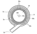
- the purge pump 3 includes a disk-shaped impeller 30 and a housing 31 that houses the impeller 30 as shown in FIGS.
- the impeller 30 has a plurality of grooves 30a arranged in parallel along the outer peripheral edge, and wings 30c are formed between the grooves 30a.
- a shaft hole 30b is formed in the center of the impeller 30 in the radial direction.
- the housing 31 includes a housing main body 31 a having an accommodation space for the impeller 30 and a lid body 31 b that covers the upper portion of the housing main body 31 a including the impeller 30.
- a suction port 3a and a discharge port 3b of the purge pump 3 are formed in the upper part of the housing body 31a.
- the suction port 3a is formed in the wall surface of the housing main body 31a.
- the discharge port 3b is formed in a nozzle shape extending outward from the housing body 31a.
- a motor 34 is housed in the lower portion of the housing main body 31a as a rotational drive means of the impeller 30.
- the motor 34 is connected to a power supply (not shown) provided in the vehicle.
- the shaft hole 30 b of the impeller 30 is inserted into the rotation shaft 34 a of the motor 34.
- the shaft hole 30b and the rotating shaft 34a have the same shape and are non-circular, for example, a shape obtained by cutting a part of a perfect circle. Therefore, by inserting the shaft hole 30b into the rotating shaft 34a, the impeller 30 is non-rotatably connected to the rotating shaft 34a.
- the impeller 30 is prevented from idling with respect to the rotating shaft 34a. Therefore, the impeller 30 rotates horizontally at the center in the radial direction of the housing 31 by rotating the rotating shaft 34a.
- a flow path 3c that connects the suction port 3a and the discharge port 3b is formed.
- the flow path 3c is provided in the housing 31 and surrounds the outer peripheral edge portion of the impeller 30 including the groove 30a. Thereby, the suction inlet 3a and the discharge outlet 3b are always connected via the flow path 3c. Therefore, the gas can flow inside the purge pump 3 even when the purge pump 3 is stopped.
- the flow path 3c has a gradually decreasing space area (cross-sectional area) from the suction port 3a to the discharge port 3b.
- the flow path 3c has a minimum diameter portion having a minimum cross-sectional area in the vicinity of the discharge port 3b. The cross-sectional area of the minimum diameter portion is larger than the cross-sectional area of the internal space in the pipes 12a to 12c of the atmospheric passage 10, the canister 2, and the purge passage 12.
- the purge passage 12 and the vapor passage 11 are branched from the common portion, with some portions in common. Strictly speaking, a part of the vapor passage 11 (between the branch portion of the vapor passage 11 and the purge passage 12 and the canister 2) is also a part of the purge passage 12. Therefore, the cross-sectional area of the minimum diameter portion of the purge pump 3 is at least equal to or larger than the minimum cross-sectional area of the vapor passage 11 (a portion common to the purge passage 12).
- a flow control valve 4 is also provided on the purge passage 12. Specifically, it is provided on the canister 2 side with respect to the purge pump 3 on the purge passage 12. That is, the flow control valve 4 is provided upstream of the purge pump 3 in the purge direction.
- the flow control valve 4 for example, an electromagnetic valve can be used.
- the flow rate control valve 4 is controlled in its opening / closing timing by an ECU (not shown) provided in the vehicle, and the valve opening rate (gas flow rate) of the purge passage 12 is controlled by duty control that is a ratio between the valve opening time and the valve closing time. Is controlled.
- a pressure sensor (not shown) that detects the pressure may be provided.
- the pressure sensor is provided between the purge pump 3 and the flow rate control valve 4 (upstream in the purge direction from the purge pump 3).
- a pressure sensor is provided between the purge pump 3 and the intake pipe 15 and / or in the intake pipe 15. Information on the detected pressure from each pressure sensor is transmitted to the ECU as a detection signal.
- the valve opening rate of the flow control valve 4 and the drive timing of the purge pump 3 are controlled by the ECU based on detection signals from the respective pressure sensors.
- the evaporated fuel generated in the fuel tank 1 flows into the canister 2 through the vapor passage 11.
- the purge pump 3 is stopped and the flow control valve 4 is completely closed. Therefore, the evaporated fuel generated in the fuel tank 1 flows to the canister 2 through the vapor passage 11, and the evaporated fuel is selectively adsorbed and captured by the adsorbent in the canister 2.
- the remaining air passes through the adsorbent and is dissipated from the canister 2 through the atmospheric passage 10 into the atmosphere. Thereby, the pressure of the fuel tank 1 is released while avoiding air pollution, and damage to the fuel tank 1 is prevented.
- the purge pump 3 and the flow rate control valve 4 are not on the path through which the evaporated fuel generated in the fuel tank 1 is adsorbed into the canister 2. Therefore, the evaporated fuel can flow to the canister 2 without being obstructed by the purge pump 3 and the flow rate control valve 4.
- the ECU controls the valve opening rate of the flow rate control valve 4 (the amount of gas flow in the purge passage 12) and the drive timing of the purge pump 3. If sufficient negative pressure is generated in the intake pipe 15, the purge pump 3 remains stopped. For example, when the ECU determines that the absolute value of the negative pressure (pressure lower than atmospheric pressure) in the intake pipe 15 is larger than a predetermined value based on a detection signal from a pressure sensor provided in the intake pipe 15, the ECU The purge pump 3 is stopped.
- gas can pass through the purge pump 3 even when the purge pump 3 is stopped. Accordingly, negative pressure from the intake pipe 15 is applied to the canister 2 and the fuel tank 1 via the purge pump 3. Thus, the evaporated fuel is desorbed from the canister 2 using only the intake pipe negative pressure. At this time, the atmosphere is also introduced into the canister 2 from the atmosphere passage 10 at the same time, thereby promoting the desorption of the evaporated fuel.
- the minimum cross-sectional area of the internal space in the purge pump 3 is larger than the cross-sectional area of the internal space in the other part of the purge passage 12.
- the path in the purge pump 3 has a larger cross-sectional area than the other part of the purge passage 12. Therefore, the pressure loss in the purge pump 3 is smaller than the pressure loss in the other part of the purge passage 12. Since the purge pump 3 hardly inhibits the gas flow, the purge pump 3 may reduce the desorption efficiency when desorbing the evaporated fuel from the canister 2 using only the negative pressure in the intake pipe 15. small. Note that when the evaporated fuel is desorbed using only the intake pipe negative pressure, the flow control valve 4 is almost fully opened. The evaporated fuel desorbed from the canister 2 is sent to the intake pipe 15 together with the evaporated fuel generated in the fuel tank 1.
- the purge pump 3 is driven. For example, when the ECU determines that the absolute value of the negative pressure in the intake pipe 15 is smaller than a predetermined value or positive pressure (pressure higher than atmospheric pressure) based on a detection signal from a pressure sensor provided in the intake pipe 15 Then, the ECU drives the purge pump 3. Thereby, the impeller 30 rotates axially, and the gas forcibly flows from the canister 2 side to the intake pipe 15 side. Thereby, a negative pressure is applied to the fuel tank 1 and the canister 2, whereby the evaporated fuel in the canister 2 is desorbed from the adsorbent. Also at this time, the desorption of the evaporated fuel is promoted by simultaneously introducing the atmosphere from the atmosphere passage 10 into the canister 2. The evaporated fuel desorbed from the canister 2 is sent to the intake pipe 15 together with the evaporated fuel generated in the fuel tank 1.
- the flow rate control valve 4 is controlled so that the pressure upstream of the purge pump 3 in the purge direction becomes a negative pressure.
- the downstream side in the purge direction from the purge pump 3 may become a positive pressure.
- the positive pressure value downstream of the purge pump 3 in the purge direction is controlled to be a negative pressure having a large absolute value upstream of the purge pump 3 in the purge direction.
- the ECU controls the opening degree of the flow control valve 4 based on detection signals from pressure sensors provided upstream and downstream of the purge pump 3. Specifically, the ECU controls the flow rate control valve 4 so that the absolute value of the negative pressure on the downstream side is larger than the absolute value of the positive pressure on the upstream side of the purge pump 3.
- the purge pump 3 may be driven by inertia even after a stop signal is transmitted from the ECU.
- the flow control valve 4 is an electromagnetic valve, it is closed immediately when a stop signal is transmitted from the ECU. Since the flow control valve 4 can be closed before the purge pump 3 stops, it is possible to suppress the gas from flowing from the purge pump 3 to the canister 2. Thereby, adverse effects on the canister 2 can be prevented.
- the evaporative fuel processing apparatus may have the form shown in FIG. 5 instead of the form shown in FIG.
- the evaporated fuel processing apparatus shown in FIG. 5 has the same basic configuration as that of the evaporated fuel processing apparatus shown in FIG. In the following, the embodiment of FIG. 5 will be described with a focus on differences from the embodiment of FIG.
- the evaporative fuel processing device further forcibly supplies gas from the intake pipe 15 for supplying air to the engine (internal combustion engine 5), the purge passage 12 that connects the intake pipe 15 and the canister 2, and the canister 2 toward the intake pipe 15.
- a purge pump 3 for pressure-feeding and a flow rate control valve 4 comprising an electromagnetic valve. The purge pump 3 and the flow rate control valve 4 are provided on the purge passage 12.
- a pipe 12d branches from a pipe 12a between the purge pump 3 and the intake pipe 15. Specifically, on the downstream side of the purge direction from the purge pump 3, the purge passage 12 is connected to the first purge passage (pipe 12 a) communicating from the purge pump 3 to the downstream side of the throttle valve 16 of the intake pipe 15 and the intake air from the purge pump 3.
- the pipe 15 branches off to a second purge passage (pipe 12d) communicating with the upstream side of the supercharger 6 of the pipe 15.
- the first and second purge passages are provided with check valves (one-way valves) 13a and 13b that enable gas flow from the purge pump 3 side only to the intake pipe 15 side, respectively.
- Both check valves 13a and 13b are opened when the differential pressure between the upstream and downstream becomes a predetermined value or more.
- the set pressure (opening pressure) of both the check valves 13a and 13b is, for example, the same.
- Evaporated fuel generated in the fuel tank 1 is adsorbed and captured in the canister 2 during parking (at key-off) or during refueling. Further, when a sufficient negative pressure is generated in the intake pipe 15 while the vehicle is running, the purge pump 3 is stopped and the evaporated fuel is desorbed using only the intake pipe negative pressure. For example, when the ECU determines that the absolute value of the negative pressure in the intake pipe 15 is larger than a predetermined value based on a detection signal from a pressure sensor provided in the intake pipe 15, the ECU stops the purge pump 3. When a sufficient negative pressure is not generated in the intake pipe 15, the purge pump 3 is driven and the flow control valve 4 is controlled to open.
- the ECU determines that the absolute value of the negative pressure in the intake pipe 15 is smaller than a predetermined value or a positive pressure based on a detection signal from a pressure sensor provided in the intake pipe 15, the ECU turns on the purge pump 3. Drive. As a result, the evaporated fuel is desorbed from the canister 2.
- the supercharger 6 exists on the intake pipe 15.
- the pressure upstream from the supercharger 6 is almost atmospheric pressure, and the pressure downstream from the supercharger 6 tends to be positive. Therefore, if the pressure downstream of the supercharger 6 is negative, the check valve 13a of the first purge passage (pipe 12a) is opened by receiving the negative pressure from the intake pipe 15 and the supply pressure from the purge pump 3. However, the gas flows through the same route as in the embodiment of FIG.
- the check valve 13a of the first purge passage (pipe 12a) does not open by receiving the positive pressure.
Landscapes
- Engineering & Computer Science (AREA)
- Mechanical Engineering (AREA)
- General Engineering & Computer Science (AREA)
- Chemical & Material Sciences (AREA)
- Combustion & Propulsion (AREA)
- Supplying Secondary Fuel Or The Like To Fuel, Air Or Fuel-Air Mixtures (AREA)
Abstract
蒸発燃料処理装置は、燃料タンク(1)、キャニスタ(2)、大気通路(10)、ベーパ通路(11)、吸気管(15)、パージ通路(12)、パージポンプ(3)、流量制御弁(4)を有する。吸気管(15)において十分な負圧が発生している場合には、吸気管(15)内の負圧のみで蒸発燃料を脱離する。吸気管(15)において十分な負圧が発生していない場合には、パージポンプ(3)を駆動して蒸発燃料をキャニスタ(2)から脱離する。パージポンプ(3)及び流量制御弁(4)は、パージ通路(12)上に設けられる。パージポンプ(3)は、駆動停止時にも気体が内部を通過可能な渦流ポンプである。パージポンプ(3)の流路における内部空間の最小断面積が、パージ通路(12)の他の部分における内部空間の最小断面積以上となっている。
Description
本発明は、蒸発燃料処理装置に関する。
蒸発燃料処理装置は、例えば燃料タンクと、燃料タンクで発生した蒸発燃料を吸着するキャニスタと、キャニスタを大気と連通する大気通路と、燃料タンクとキャニスタとを連通するベーパ通路を有する。さらに蒸発燃料処理装置は、内燃機関へ大気を供給する吸気管と、吸気管とキャニスタとを連通するパージ通路と、キャニスタから吸気管へ向けて気体を強制的に圧送するパージポンプを有する。吸気管において十分な負圧が発生している場合にはパージポンプを停止して吸気管の負圧のみを利用してキャニスタ内から蒸発燃料を脱離(パージ)する。吸気管において十分な負圧が発生していない場合にはパージポンプを駆動してキャニスタ内から蒸発燃料を脱離(パージ)する。
この種の蒸発燃料処理装置は、例えば特開2002-256986号公報や特開2007-162588号公報に開示されている。特開2002-256986号公報では、パージポンプが破損した時でもキャニスタから燃料蒸気が大気中へ放散されるのを防止するために、パージポンプとして複動型のダイヤフラムポンプを使用している。これにより、パージポンプが破損してもポンプ停止時の通路密閉性が確保される。
特開2007-162588号公報では、パージポンプとして特殊なベーンポンプを採用している。該ベーンポンプは、複数のベーンを回転中心に引き寄せる引張バネ等のベーン収容手段を有する。したがって、パージポンプの駆動中は、引張バネが遠心力により伸びてベーンが径方向外方に飛び出すことで、気体を圧送する。一方、パージポンプの停止中は、引張バネの付勢力によって各ベーンが回転中心に引き寄せられることで、吸入側と吐出側が連通する。これにより、パージポンプの駆動停止中でも気体の流路が確保されることで、蒸発燃料の脱離効率を向上している。なお、特開2007-162588号公報ではパージポンプが大気通路上に設けられている。しかし、パージポンプの駆動停止中でも気体の流路が確保されていることで、給油時の気体流動も確保される。
特開2002-256986号公報では、パージポンプを停止すると通路が完全に密閉(遮断)される。そのため、吸気管の負圧のみを利用してキャニスタから蒸発燃料を脱離する際の効率が極めて悪い。これを避けるため、バイパス弁が設けられたバイパス経路を形成する形態も開示されている。しかし、これでは部品点数の増大に伴うコストアップや、装置の大型・複雑化が避けられない。
一方、特開2007-162588号公報ではポンプ停止時でも気体が内部を通過可能なベーンポンプを使用しているため、特開2002-256986号公報のような問題は生じない。しかし、特開2007-162588号公報では特殊なベーンポンプを使用する必要がある。しかも、ベーンポンプ内における気体流路となる内部空間の大きさ(断面積)については考慮していない。したがって、吸込口から吐出口に至るベーンポンプの内部空間の最小断面積が、パージ通路における内部空間の最小断面積より小さいと、ベーンポンプが通路抵抗(圧損部)となり、蒸発燃料の脱離効率が阻害される。しかも、特開2007-162588号公報ではベーンポンプが大気通路上に設けられているので、給油時の気体流動も阻害してしまう。
したがって、吸気管において十分な負圧が発生している場合にパージポンプを停止し、吸気管の負圧のみを利用してキャニスタ内から蒸発燃料を脱離する際における脱離効率が阻害されることの小さい蒸発燃料処理装置が従来必要とされている。
本発明の1つの特徴によると、蒸発燃料処理装置は、燃料タンクと、燃料タンクで発生した蒸発燃料を吸着するキャニスタと、キャニスタを大気と連通する大気通路と、燃料タンクとキャニスタとを連通するベーパ通路を有する。蒸発燃料処理装置は、さらに内燃機関へ大気を供給する吸気管と、吸気管とキャニスタとを連通するパージ通路と、キャニスタから吸気管へ向けて気体を強制的に圧送するパージポンプを有する。吸気管の負圧の絶対値が所定値よりも大きい場合には、パージポンプを停止して吸気管内の負圧を利用してキャニスタ内から蒸発燃料を脱離する。吸気管の負圧の絶対値が前記所定値よりも小さいまたは吸気管の圧力が正圧の場合には、パージポンプを駆動して強制的に気体を圧送し、キャニスタ内から蒸発燃料を脱離する。キャニスタ内から蒸発燃料を脱離する際は、大気通路から大気がパージ促進用の空気として導入されながら、キャニスタ及びパージ通路を通して吸気管へ気体が流動していく。「気体」は、例えばパージ促進用の空気(大気)と蒸発燃料の一方または双方を含む。「気体」は、例えば蒸発燃料含有ガスと換言できる場合もある。
パージポンプは、パージ通路上に設けられる。パージポンプは、駆動停止時にも気体が内部を通過可能な渦流ポンプである。パージポンプは、外周縁に沿って複数の溝または羽が並設された円板状のインペラと、インペラを収容し、吸込口と吐出口を備えるハウジングを有する。インペラは、ハウジング内において軸回転する。ハウジング内には、インペラの外周縁部を囲むように流路が形成され、吸込口と吐出口が流路によって常時連通している。パージポンプの吸込口から流路を介した吐出口に至る経路における内部空間の最小断面積が、大気通路、キャニスタ、及びパージ通路の配管における内部空間の最小断面積以上となっている。
すなわち、パージポンプ内経路の最小断面積は、キャニスタから蒸発燃料を脱離する際の気体流動経路となる大気通路、キャニスタ、及びパージ通路の配管における最小断面積以上となっている。これにより、パージポンプの吸込口から流路を介した吐出口に至る経路における単位長さ当たりの圧力損失が、大気通路、キャニスタ、及びパージ通路の配管における単位長さ当たりの圧力損失以下となる。「長さ」は、例えば気体流動方向の寸法である。「キャニスタの内部空間の断面積」は、例えば蒸発燃料を吸着する吸着材が収容されている吸着室において、各吸着材間に形成される空隙面積の総和である。
したがってキャニスタから蒸発燃料を脱離する際、吸気管内の負圧のみを利用する場合においてパージポンプ内を気体が流動できる。パージポンプは、渦流ポンプであって、特殊な構造を備える従来のベーンポンプに比べて容易に構成される。またパージポンプにおける内部空間の最小断面積は、パージ通路を構成する他の部分における最小断面積以上となっている。これにより、パージポンプ内における圧力損失がパージ通路を構成する他の部分における圧力損失より小さくなる。吸気管内の負圧のみによって蒸発燃料をキャニスタから脱離する際に、パージポンプが通路抵抗(圧損部)となることが確実に避けられる。而して、吸気管内の負圧のみを利用して蒸発燃料を脱離する際の脱離効率が阻害されることを回避できる。
他の特徴においてパージ通路上のパージポンプよりもキャニスタ側に、流量制御弁を設けても良い。すなわち、蒸発燃料を脱離する際の気体の流動方向をパージ方向と定義すると、流量制御弁を設ける場合は、例えばパージポンプよりもパージ方向上流に設ける。
パージポンプよりもパージ方向上流に流量制御弁を設けていれば、例えば次のようなメリットがある。第1に、吸気管の負圧の程度等に応じてパージ通路やキャニスタ内の負圧の程度を制御可能である。第2に、パージポンプの停止と同時に流量制御弁を閉弁してパージ通路を遮断すれば、パージポンプの停止直後にキャニスタに正圧が作用して蒸発燃料が大気通路を通して大気中に放散されることを防止できる。第3に、給油時等に流量制御弁を閉弁してパージ通路を遮断すれば、燃料タンクからの蒸発燃料を確実にキャニスタへ送ることができる。
他の特徴においてパージポンプ及び流量制御弁は、燃料タンクへの給油時において燃料タンクからの気体の流動経路上に設けられていない。
蒸発燃料処理装置は、自動車等の車輌に適用されるものであって、図1に示すように、燃料タンク1と、キャニスタ2と、パージポンプ3と、流量制御弁4を有する。さらに蒸発燃料処理装置は、キャニスタ2を大気と連通する大気通路10と、燃料タンク1とキャニスタ2とを連通するベーパ通路11と、吸気管15と、吸気管15とキャニスタ2とを連通するパージ通路12とを有する。
燃料タンク1は、耐圧性を有する密閉タンクである。燃料タンク1内には、ガソリン等の揮発性の高い燃料が貯留される。燃料タンク1内には、燃料をエンジン(内燃機関5)へ圧送する燃料ポンプ(図示せず)が配されている。
キャニスタ2は、燃料タンク1で発生した蒸発燃料を選択的に吸着・脱離する。キャニスタ2の内部には、吸着材(図示せず)が充填されている。吸着材としては、空気は通すが蒸発燃料を吸着・脱離可能な多孔質体を使用できる。このような多孔質体としては、活性炭を好適に使用できる。
吸気管15は、内燃機関(エンジン)5へ大気を吸気供給する管である。吸気管15内には、エンジンコントロールユニット(ECU)(図示せず)により開弁量が制御されるスロットルバルブ16が設けられている。スロットルバルブ16の開弁量は、図視省略のアクセルの踏み込み量等に応じて制御される。
ベーパ通路11は、例えば配管であって、燃料タンク1とキャニスタ2を連通する。パージ通路12は、吸気管15と大気通路10とを連通する。パージ通路12は、吸気管15とパージポンプ3を連通する配管12aと、パージポンプ3と流量制御弁4を連通する配管12bと、流量制御弁4とキャニスタ2を連通する配管12cを有する。配管12cは、ベーパ通路11から分岐している。すなわち配管12cは、ベーパ通路11との分岐部分と流量制御弁4とを連通する部分と、ベーパ通路11の一部でもありかつ分岐部分とキャニスタ2とを連通する部分を有する。すなわちパージ通路12は、配管12a~12c、キャニスタ2、流量制御弁4、パージポンプ3を有し、これらによって大気通路10と吸気管15を連通させる。パージ通路12は、吸気管15内のスロットルバルブ16より下流において吸気管15と連通している。
パージポンプ3は、キャニスタ2から吸気管15へ向けて気体を強制的に圧送するものであって、パージ通路12上に設けられ、例えば吸気管15とキャニスタ2との間に設けられる。パージポンプ3としては、渦流ポンプ(ターボポンプ)を使用している。なお、渦流ポンプはウェスコポンプとも称される。
パージポンプ3は、図2~4に示すように、円板状のインペラ30と、当該インペラ30を収容するハウジング31とを有する。インペラ30は、外周縁に沿って複数の溝30aが並設され、溝30aの間に羽30cが形成される。インペラ30の径方向中央には、軸孔30bが穿設されている。ハウジング31は、インペラ30の収容空間を備えるハウジング本体31aと、インペラ30を含めてハウジング本体31aの上方を覆う蓋体31bとを有する。ハウジング本体31aの上部には、パージポンプ3の吸込口3aと吐出口3bとが形成されている。吸込口3aは、ハウジング本体31aの壁面に形成されている。吐出口3bは、ハウジング本体31aから外方に延在するノズル状に形成されている。
ハウジング本体31aの下部には、インペラ30の回転駆動手段としてモータ34が収容されている。モータ34は、車輌に設けられた図視省略の電源と連結されている。インペラ30をハウジング31内に収容する際、モータ34の回転軸34aにインペラ30の軸孔30bを挿通する。軸孔30bと回転軸34aは、同一形状であって、かつ非円形であり、例えば真円の一部が切断された形状である。したがって軸孔30bを回転軸34aに挿入することで、インペラ30が回転軸34aに対して回転不能に連結される。かくしてインペラ30が回転軸34aに対して空回りすることが防止される。そのため回転軸34aが回転することでインペラ30がハウジング31の径方向中央において水平に軸回転する。
ハウジング本体31aと蓋体31bの間には、吸込口3aと吐出口3bを連通する流路3cが形成されている。流路3cは、ハウジング31内に設けられて、溝30aを含むインペラ30の外周縁部を囲んでいる。これにより吸込口3aと吐出口3bが流路3cを介して常時連通している。したがって、パージポンプ3の駆動停止中でも、パージポンプ3の内部を気体が流動可能となっている。流路3cは、吸込口3aから吐出口3bにかけて徐々に空間面積(断面積)が小さくなっている。流路3cは、吐出口3bの近傍において最小断面積となる最小径部分を有する。最小径部分の断面積は、大気通路10、キャニスタ2、及びパージ通路12の配管12a~12cにおける内部空間の断面積以上の大きさを有している。
パージ通路12とベーパ通路11は、一部を共通として、共通部分から分岐している。厳密に言えばベーパ通路11の一部(ベーパ通路11とパージ通路12の分岐部からキャニスタ2までの間)は、パージ通路12の一部でもある。したがって、パージポンプ3の最小径部分の断面積は、少なくともベーパ通路11の一部(パージ通路12との共通部分)における最小断面積以上になっている。
流量制御弁4も、パージ通路12上に設けられる。詳しくは、パージ通路12上において、パージポンプ3よりもキャニスタ2側に設けられる。すなわち、流量制御弁4はパージポンプ3よりもパージ方向上流に設けられている。流量制御弁4としては、例えば電磁弁を使用できる。流量制御弁4は、車輌に設けられる図視省略のECUによって開閉タイミングが制御され、開弁時間と閉弁時間との比からなるデューティ制御により、パージ通路12の開弁率(気体流動量)が制御される。
圧力を検知する図示省略の圧力センサが設けられても良い。例えば圧力センサは、パージポンプ3と流量制御弁4との間(パージポンプ3よりもパージ方向上流側)に設けられる。加えて、あるいは代えてパージポンプ3と吸気管15との間と吸気管15のいずれか一方または双方に圧力センサが設けられる。各圧力センサからの検知圧力の情報は、検知信号としてECUに送信される。流量制御弁4の開弁率及びパージポンプ3の駆動タイミングは、各圧力センサからの検知信号に基づき、ECUによって制御される。
次に、蒸発燃料処理装置による蒸発燃料の処理機構について説明する。駐車中(キーオフ時)や給油時には、燃料タンク1内で発生した蒸発燃料が、ベーパ通路11を通してキャニスタ2内に流入する。このとき、パージポンプ3は停止しており、流量制御弁4は完全に閉弁している。したがって燃料タンク1において発生した蒸発燃料は、ベーパ通路11を通ってキャニスタ2へ流れ、キャニスタ2内の吸着材によって蒸発燃料が選択的に吸着捕捉される。残余の空気は吸着材を透過し、キャニスタ2から大気通路10を通して大気中に放散される。これにより、大気汚染を回避しながら燃料タンク1が圧力開放され、燃料タンク1の破損が防止される。そしてパージポンプ3及び流量制御弁4は、燃料タンク1で発生した蒸発燃料がキャニスタ2内へ吸着されていく経路上にはない。そのため蒸発燃料は、パージポンプ3及び流量制御弁4によって邪魔されることなく、キャニスタ2へ流れ得る。
車輌走行中は、ECUによって流量制御弁4の開弁率(パージ通路12の気体流動量)とパージポンプ3の駆動タイミングが制御される。吸気管15において十分な負圧が発生している場合は、パージポンプ3は停止したままである。例えば吸気管15に設けられた圧力センサからの検出信号に基づき、ECUが吸気管15の負圧(大気圧よりも低い圧力)の絶対値が所定値よりも大きいと判断した際に、ECUがパージポンプ3を停止させる。
しかし、パージポンプ3の停止中でも気体はパージポンプ3内を通過可能である。したがって、吸気管15からの負圧がパージポンプ3を介してキャニスタ2及び燃料タンク1内へ印加される。これにより、吸気管負圧のみを利用して蒸発燃料がキャニスタ2内から脱離される。このとき、大気通路10からキャニスタ2内へ大気も同時に導入されることで、蒸発燃料の脱離が促進される。
しかも、パージポンプ3における内部空間の最小断面積がパージ通路12の他の部分における内部空間の断面積よりも大きくなっている。換言すると、パージポンプ3内の経路は、パージ通路12の他の部分よりも断面積が大きくなっている。したがってパージポンプ3における圧力損失は、パージ通路12の他の部分における圧力損失よりも小さい。パージポンプ3によって気体流動が阻害されることが少ないため、吸気管15内の負圧のみを利用してキャニスタ2から蒸発燃料を脱離する際の脱離効率がパージポンプ3によって低下することが小さい。なお、吸気管負圧のみを利用して蒸発燃料を脱離する際は、流量制御弁4はほぼ全開している。キャニスタ2から脱離した蒸発燃料は、燃料タンク1内で発生した蒸発燃料と共に吸気管15へ送給される。
吸気管15において十分な負圧が発生していないか、大気圧に近い場合は、パージポンプ3が駆動される。例えば吸気管15に設けられた圧力センサからの検出信号に基づき、ECUが吸気管15の負圧の絶対値が所定値よりも小さい、または正圧(大気圧よりも高い圧力)と判断した際に、ECUがパージポンプ3を駆動させる。これによりインペラ30が軸回転して、キャニスタ2側から吸気管15側へ気体が強制的に流動する。これにより、燃料タンク1及びキャニスタ2へ負圧が印加されることで、キャニスタ2内の蒸発燃料が吸着材から脱離される。このときも、大気通路10からキャニスタ2内へ大気も同時に導入されることで、蒸発燃料の脱離が促進される。キャニスタ2から脱離された蒸発燃料は、燃料タンク1内で発生した蒸発燃料と共に吸気管15へ送給される。
パージポンプ3の駆動中は、流量制御弁4によってパージポンプ3よりもパージ方向上流側の圧力が負圧となるように制御されている。特に、パージポンプ3の駆動中、吸気管15内の圧力が大気圧に近い場合は、パージポンプ3よりもパージ方向下流側が正圧となる場合もある。この場合、パージポンプ3よりもパージ方向下流側の正圧値に対して、パージポンプ3よりもパージ方向上流側は絶対値の大きな負圧となるように制御されている。例えばパージポンプ3の駆動中において、ECUがパージポンプ3の上流側と下流側に設けられた圧力センサからの検出信号に基づいて流量制御弁4の開度を制御する。具体的には、パージポンプ3の上流側の正圧の絶対値よりも下流側の負圧の絶対値が大きくなるように、ECUが流量制御弁4を制御する。
したがって、パージポンプ3を停止した後は、パージ方向下流側の正圧がパージ方向上流側の大きな負圧によって相殺される。これにより、パージポンプ3を停止した直後に、キャニスタ2に正圧が印加されることを抑制できる。そのため、パージポンプ3を停止した直後に、キャニスタ2内の蒸発燃料が大気通路10を通して大気中へ放散されることを抑制できる。また、パージポンプ3は、ECUからの停止信号が発信された後でも惰性駆動することがある。一方、流量制御弁4は電磁弁なので、ECUからの停止信号が発信されれば直ちに閉弁する。パージポンプ3が停止する前に流量制御弁4を閉じることができるため、パージポンプ3からキャニスタ2へ気体が流れることを抑制できる。これによりキャニスタ2への悪影響を防止できる。
蒸発燃料処理装置は、図1に示す形態に代えて図5に示す形態であっても良い。図5に示す蒸発燃料処理装置は、図1に示す蒸発燃料処理装置と同様の基本的構成を有し、同様の作用効果を奏する。以下に、図1の形態と相違する点を中心に図5の形態について説明する。
図5の蒸発燃料処理装置も、燃料タンク1と、燃料タンク1で発生した蒸発燃料を吸着するキャニスタ2と、キャニスタ2を大気と連通する大気通路10と、燃料タンク1とキャニスタ2とを連通するベーパ通路11を有する。蒸発燃料処理装置は、さらにエンジン(内燃機関5)へ大気を供給する吸気管15と、吸気管15とキャニスタ2とを連通するパージ通路12と、キャニスタ2から吸気管15へ向けて気体を強制的に圧送するパージポンプ3と、電磁弁からなる流量制御弁4とを有する。パージポンプ3及び流量制御弁4は、パージ通路12上に設けられている。
図5の蒸発燃料処理装置は、スロットルバルブ16よりも上流側における吸気管15上に過給器6を有する。パージポンプ3と吸気管15との間の配管12aから配管12dが分岐している。詳しくは、パージポンプ3よりもパージ方向下流において、パージ通路12は、パージポンプ3から吸気管15のスロットルバルブ16よりも下流に連通する第1パージ通路(配管12a)と、パージポンプ3から吸気管15の過給器6よりも上流側に連通する第2パージ通路(配管12d)とに分岐している。第1・第2パージ通路(配管12a・12d)には、パージポンプ3側から吸気管15側のみへの気体流動を可能とするチェック弁(一方弁)13a・13bがそれぞれ設けられている。両チェック弁13a・13bは、上流と下流との差圧が所定値以上となった場合に開弁する。両チェック弁13a・13bの設定圧力(開弁圧力)は、例えばそれぞれ同じである。
駐車中(キーオフ時)や給油時に、燃料タンク1内で発生した蒸発燃料がキャニスタ2内へ吸着捕捉される。また、車輌走行中に吸気管15において十分な負圧が発生している場合には、パージポンプ3を停止して吸気管負圧のみを利用して蒸発燃料を脱離する。例えば吸気管15に設けられた圧力センサからの検出信号に基づき、ECUが吸気管15の負圧の絶対値が所定値よりも大きいと判断した際に、ECUがパージポンプ3を停止させる。吸気管15において十分な負圧が発生していない場合には、パージポンプ3を駆動すると共に流量制御弁4を開弁制御する。例えば吸気管15に設けられた圧力センサからの検出信号に基づき、ECUが吸気管15の負圧の絶対値が所定値よりも小さい、あるいは正圧と判断した際に、ECUがパージポンプ3を駆動させる。これによって蒸発燃料がキャニスタ2から脱離される。
図5の蒸発燃料処理装置では、吸気管15上に過給器6が存在する。この場合、過給器6より上流はほぼ大気圧であり、過給器6より下流は正圧となり易い。したがって、過給器6よりも下流が負圧であれば、吸気管15からの負圧とパージポンプ3からの送給圧を受けて第1パージ通路(配管12a)のチェック弁13aが開弁し、図1の形態と同様のルートで気体が流動する。一方、過給器6より下流が正圧となっていれば、第1パージ通路(配管12a)のチェック弁13aは、当該正圧を受けることで開弁しない。過給器6より下流の圧力が正圧でかつ過給器6より上流の圧力よりも高い場合には、第2パージ通路(配管12d)のチェック弁13bがパージポンプ3からの送給圧を受けて開弁される。これにより第2パージ通路(配管12d)を通して気体が流動する。
添付の図面を参照して詳細に上述した種々の実施例は、本発明の代表例であって本発明を限定するものではありません。詳細な説明は、本教示の様々な態様を作成、使用および/または実施するために、当業者に教示するものであって、本発明の範囲を限定するものではありません。更に、上述した各付加的な特徴および教示は、改良された蒸発燃料処理装置および/またはその製造方法と使用方法を提供するため、別々にまたは他の特徴および教示と一緒に適用および/または使用され得るものです。
Claims (4)
- 燃料タンクと、
該燃料タンクで発生した蒸発燃料を吸着するキャニスタと、
該キャニスタを大気と連通する大気通路と、
前記燃料タンクと前記キャニスタとを連通するベーパ通路と、
内燃機関へ大気を供給する吸気管と、
前記吸気管と前記キャニスタとを連通するパージ通路と、
前記キャニスタから前記吸気管へ向けて気体を強制的に圧送するパージポンプと、
を有し、
前記吸気管の負圧の絶対値が所定値よりも大きい場合には前記パージポンプを停止して前記負圧を利用して前記キャニスタ内から蒸発燃料を脱離し、前記吸気管の負圧の絶対値が前記所定値よりも小さいまたは前記吸気管の圧力が正圧の場合には前記パージポンプを駆動して前記キャニスタ内から蒸発燃料を脱離し、
前記キャニスタ内から蒸発燃料を脱離する際は、前記大気通路から大気が導入されながら前記キャニスタ及び前記パージ通路を通して前記吸気管へ気体が流動し、
前記パージポンプは、前記パージ通路上に設けられ、
該パージポンプは、外周縁に沿って複数の溝または羽が並設された円板状のインペラと、該インペラを収容し、吸込口と吐出口とを備えるハウジングとを有し、前記インペラは前記ハウジング内において軸回転し、前記ハウジング内には前記インペラの外周縁部を囲むように流路が形成され、前記吸込口と前記吐出口とが前記流路によって常時連通している渦流ポンプであり、
前記パージポンプの前記吸込口から前記吐出口に至る前記流路における内部空間の最小断面積が、前記大気通路、前記キャニスタ、及び前記パージ通路の配管における内部空間の最小断面積以上となっている、蒸発燃料処理装置。 - 燃料タンクと、
該燃料タンクで発生した蒸発燃料を吸着するキャニスタと、
該キャニスタを大気と連通する大気通路と、
前記燃料タンクと前記キャニスタとを連通するベーパ通路と、
内燃機関へ大気を供給する吸気管と、
該吸気管と前記キャニスタとを連通するパージ通路と、
前記キャニスタから前記吸気管へ向けて気体を強制的に圧送するパージポンプと、
を有し、
前記吸気管の負圧の絶対値が所定値よりも大きい場合には前記パージポンプを停止して前記負圧を利用して前記キャニスタ内から蒸発燃料を脱離し、前記吸気管の負圧の絶対値が前記所定値よりも小さいまたは前記吸気管の圧力が正圧の場合には前記パージポンプを駆動して前記キャニスタ内から蒸発燃料を脱離し、
前記キャニスタ内から蒸発燃料を脱離する際は、前記大気通路から大気が導入されながら前記キャニスタ及び前記パージ通路を通して前記吸気管へ気体が流動し、
前記パージポンプは、前記パージ通路上に設けられ、
該パージポンプは、外周縁に沿って複数の溝または羽が並設された円板状のインペラと、該インペラを収容し、吸込口と吐出口とを備えるハウジングとを有し、前記インペラは前記ハウジング内において軸回転し、前記ハウジング内には前記インペラの外周縁部を囲むように流路が形成され、前記吸込口と前記吐出口とが前記流路によって常時連通している渦流ポンプであり、
前記パージポンプの前記吸込口から前記吐出口に至る前記流路における単位長さ当たりの圧力損失が、前記大気通路、前記キャニスタ、及び前記パージ通路の配管における単位長さ当たりの圧力損失以下となっている、蒸発燃料処理装置。 - 請求項1または請求項2に記載の蒸発燃料処理装置であって、
前記パージ通路上の前記パージポンプよりも前記キャニスタ側に、流量制御弁が設けられている、蒸発燃料処理装置。 - 請求項1ないし請求項3のいずれか一項に記載の蒸発燃料処理装置であって、
前記パージポンプ及び前記流量制御弁は、前記燃料タンクへの給油時において前記燃料タンクからの気体の流動経路上に無い、蒸発燃料処理装置。
Priority Applications (3)
| Application Number | Priority Date | Filing Date | Title |
|---|---|---|---|
| CN201680024001.7A CN107532545A (zh) | 2015-05-15 | 2016-03-23 | 蒸发燃料处理装置 |
| US15/571,260 US10415511B2 (en) | 2015-05-15 | 2016-03-23 | Evaporated fuel processing devices |
| DE112016001805.3T DE112016001805B4 (de) | 2015-05-15 | 2016-03-23 | Bearbeitungseinrichtung für verdampften Kraftstoff |
Applications Claiming Priority (2)
| Application Number | Priority Date | Filing Date | Title |
|---|---|---|---|
| JP2015-099976 | 2015-05-15 | ||
| JP2015099976A JP6441167B2 (ja) | 2015-05-15 | 2015-05-15 | 蒸発燃料処理装置 |
Publications (1)
| Publication Number | Publication Date |
|---|---|
| WO2016185786A1 true WO2016185786A1 (ja) | 2016-11-24 |
Family
ID=57319992
Family Applications (1)
| Application Number | Title | Priority Date | Filing Date |
|---|---|---|---|
| PCT/JP2016/059105 Ceased WO2016185786A1 (ja) | 2015-05-15 | 2016-03-23 | 蒸発燃料処理装置 |
Country Status (5)
| Country | Link |
|---|---|
| US (1) | US10415511B2 (ja) |
| JP (1) | JP6441167B2 (ja) |
| CN (1) | CN107532545A (ja) |
| DE (1) | DE112016001805B4 (ja) |
| WO (1) | WO2016185786A1 (ja) |
Families Citing this family (18)
| Publication number | Priority date | Publication date | Assignee | Title |
|---|---|---|---|---|
| JP6594750B2 (ja) * | 2015-11-24 | 2019-10-23 | 愛三工業株式会社 | 渦流ポンプ |
| EP3592966B1 (en) * | 2017-03-06 | 2021-06-09 | HELLA GmbH & Co. KGaA | Purge pump system with emergency stop |
| JP6728099B2 (ja) * | 2017-04-28 | 2020-07-22 | 愛三工業株式会社 | 蒸発燃料処理装置 |
| JP6749867B2 (ja) | 2017-06-13 | 2020-09-02 | 愛三工業株式会社 | 蒸発燃料処理装置及び制御装置 |
| KR20190071330A (ko) * | 2017-12-14 | 2019-06-24 | 현대자동차주식회사 | 캐니스터 퍼지 시스템 및 캐니스터 퍼지 시스템의 퍼지 밸브 진단 방법 |
| KR102417369B1 (ko) * | 2017-12-18 | 2022-07-05 | 현대자동차 주식회사 | 능동형 연료 증기 퍼지 시스템 및 이를 이용한 제어 방법 |
| KR20190085261A (ko) * | 2018-01-10 | 2019-07-18 | 현대자동차주식회사 | 액티브 캐니스터 퍼지시스템 및 그 제어방법 |
| JP2019152169A (ja) * | 2018-03-05 | 2019-09-12 | 愛三工業株式会社 | 蒸発燃料処理装置及びそれを備えたエンジンの燃料噴射制御装置 |
| KR102484937B1 (ko) * | 2018-05-15 | 2023-01-04 | 현대자동차주식회사 | 차량의 캐니스터 퍼지 제어 방법 |
| DE102018207891A1 (de) * | 2018-05-18 | 2019-11-21 | Robert Bosch Gmbh | Seitenkanalverdichter für ein Brennstoffzellensystem zur Förderung und/oder Verdichtung von einem gasförmigen Medium |
| JP7004619B2 (ja) * | 2018-07-17 | 2022-01-21 | 愛三工業株式会社 | 蒸発燃料処理装置 |
| JP7317477B2 (ja) * | 2018-09-25 | 2023-07-31 | 愛三工業株式会社 | ポンプ及びその車両搭載方法 |
| KR20200089962A (ko) * | 2019-01-18 | 2020-07-28 | 현대자동차주식회사 | 액티브 퍼지 펌프를 활용한 리크 진단 시스템 및 액티브 퍼지 펌프를 활용한 리크 진단 방법 |
| KR102703068B1 (ko) * | 2019-02-26 | 2024-09-05 | 현대자동차주식회사 | 액티브 퍼지 시스템 작동시 퍼지 잔류 가스 제거 방법 |
| CN112128024B (zh) * | 2019-06-24 | 2021-10-08 | 联合汽车电子有限公司 | 一种炭罐阀脱落诊断方法、诊断装置和汽车 |
| JP7205432B2 (ja) * | 2019-09-23 | 2023-01-17 | 浜名湖電装株式会社 | パージ制御弁装置 |
| KR20220085078A (ko) * | 2020-12-14 | 2022-06-22 | 현대자동차주식회사 | 하이브리드 차량의 능동형 증발가스 퍼지 시스템 및 하이브리드 차량의 능동형 증발가스 퍼지 방법 |
| CN114837865B (zh) * | 2022-05-27 | 2023-07-07 | 陕西柴油机重工有限公司 | 用于柴油机应急停车的高压油泵停油控制装置 |
Citations (7)
| Publication number | Priority date | Publication date | Assignee | Title |
|---|---|---|---|---|
| JPS58160590A (ja) * | 1982-03-17 | 1983-09-24 | Fuji Electric Co Ltd | 渦流ポンプ |
| JP2002256986A (ja) * | 2001-03-02 | 2002-09-11 | Denso Corp | 燃料蒸気処理装置 |
| JP2003042014A (ja) * | 2001-07-26 | 2003-02-13 | Toyota Motor Corp | キャニスタパージシステム |
| JP2006283702A (ja) * | 2005-04-01 | 2006-10-19 | Denso Corp | 電動エアポンプ装置、および蒸発燃料処理装置 |
| JP2007162588A (ja) * | 2005-12-14 | 2007-06-28 | Denso Corp | 蒸発燃料処理装置 |
| US20130319378A1 (en) * | 2010-12-28 | 2013-12-05 | Robert Bosch Gmbh | Venting system, in particular for a fuel tank |
| JP2015229925A (ja) * | 2014-06-03 | 2015-12-21 | 株式会社デンソー | 蒸発燃料処理装置 |
Family Cites Families (10)
| Publication number | Priority date | Publication date | Assignee | Title |
|---|---|---|---|---|
| US5257916A (en) * | 1992-11-27 | 1993-11-02 | Walbro Corporation | Regenerative fuel pump |
| US5702229A (en) * | 1996-10-08 | 1997-12-30 | Walbro Corporation | Regenerative fuel pump |
| JP3338644B2 (ja) * | 1997-12-09 | 2002-10-28 | 株式会社ユニシアジェックス | 内燃機関の蒸発燃料処理装置 |
| DE19831188C2 (de) * | 1998-07-11 | 2003-05-08 | Freudenberg Carl Kg | Tankentlüftungseinrichtung für Kraftfahrzeuge |
| AU2003228067B2 (en) * | 2002-04-22 | 2008-05-29 | Recopharma Ab | Mucin fusion polypeptide vaccines, compositions and methods of use thereof |
| DE10236387A1 (de) * | 2002-08-08 | 2004-02-19 | Robert Bosch Gmbh | Vorrichtung zum dosierten Zumischen von verflüchtigtem Kraftstoff in ein Ansaugrohr einer Brennkraftmaschine |
| JP2007092659A (ja) * | 2005-09-29 | 2007-04-12 | Denso Corp | 流体ポンプ装置 |
| DE102010048313A1 (de) * | 2010-10-14 | 2012-04-19 | Continental Automotive Gmbh | Verfahren und Vorrichtung zum Betreiben eines Tankentlüftungssystems |
| JP6058290B2 (ja) * | 2011-07-19 | 2017-01-11 | 東芝メディカルシステムズ株式会社 | 画像処理システム、装置、方法及び医用画像診断装置 |
| JP6225805B2 (ja) * | 2014-04-07 | 2017-11-08 | 株式会社デンソー | 蒸発燃料処理装置 |
-
2015
- 2015-05-15 JP JP2015099976A patent/JP6441167B2/ja not_active Expired - Fee Related
-
2016
- 2016-03-23 CN CN201680024001.7A patent/CN107532545A/zh active Pending
- 2016-03-23 WO PCT/JP2016/059105 patent/WO2016185786A1/ja not_active Ceased
- 2016-03-23 DE DE112016001805.3T patent/DE112016001805B4/de not_active Expired - Fee Related
- 2016-03-23 US US15/571,260 patent/US10415511B2/en not_active Expired - Fee Related
Patent Citations (7)
| Publication number | Priority date | Publication date | Assignee | Title |
|---|---|---|---|---|
| JPS58160590A (ja) * | 1982-03-17 | 1983-09-24 | Fuji Electric Co Ltd | 渦流ポンプ |
| JP2002256986A (ja) * | 2001-03-02 | 2002-09-11 | Denso Corp | 燃料蒸気処理装置 |
| JP2003042014A (ja) * | 2001-07-26 | 2003-02-13 | Toyota Motor Corp | キャニスタパージシステム |
| JP2006283702A (ja) * | 2005-04-01 | 2006-10-19 | Denso Corp | 電動エアポンプ装置、および蒸発燃料処理装置 |
| JP2007162588A (ja) * | 2005-12-14 | 2007-06-28 | Denso Corp | 蒸発燃料処理装置 |
| US20130319378A1 (en) * | 2010-12-28 | 2013-12-05 | Robert Bosch Gmbh | Venting system, in particular for a fuel tank |
| JP2015229925A (ja) * | 2014-06-03 | 2015-12-21 | 株式会社デンソー | 蒸発燃料処理装置 |
Also Published As
| Publication number | Publication date |
|---|---|
| JP2016217172A (ja) | 2016-12-22 |
| US10415511B2 (en) | 2019-09-17 |
| JP6441167B2 (ja) | 2018-12-19 |
| US20180347511A1 (en) | 2018-12-06 |
| DE112016001805T5 (de) | 2018-01-11 |
| CN107532545A (zh) | 2018-01-02 |
| DE112016001805B4 (de) | 2022-03-17 |
Similar Documents
| Publication | Publication Date | Title |
|---|---|---|
| JP6441167B2 (ja) | 蒸発燃料処理装置 | |
| JP5961026B2 (ja) | 蒸発燃料処理装置 | |
| JP6522373B2 (ja) | 蒸発燃料処理装置 | |
| JP6319036B2 (ja) | 燃料蒸発ガスパージシステム | |
| US9611816B2 (en) | System and method for improving canister purging | |
| JP4800271B2 (ja) | 蒸発燃料排出抑制装置 | |
| US9574507B2 (en) | System and method for improving canister purging | |
| US20140299111A1 (en) | Venting system for a fuel tank | |
| JP6040962B2 (ja) | 蒸発燃料処理装置 | |
| JP3274084B2 (ja) | キャニスタ | |
| JP3211618B2 (ja) | 蒸発燃料排出防止装置 | |
| JP2016164386A (ja) | 蒸発燃料処理装置 | |
| CN103321789B (zh) | 蒸气回收系统抽送阀及方法 | |
| US10557442B2 (en) | Purge ejector assembly for an engine | |
| JP5702758B2 (ja) | 蒸発燃料処理装置 | |
| US10598138B2 (en) | Hermetically sealed tank system | |
| JP6404173B2 (ja) | 蒸発燃料処理装置 | |
| CN216665965U (zh) | 燃油蒸气泵组件及包括其的燃油蒸发排放控制系统 | |
| JP2015081528A (ja) | 蒸発燃料処理装置 | |
| JP5991250B2 (ja) | 蒸発燃料処理装置 | |
| CN116241485B (zh) | 燃油蒸气泵组件及包括其的燃油蒸发排放控制系统 | |
| JPH0861162A (ja) | 自動車用蒸発燃料制御装置 | |
| JP2007205231A (ja) | 蒸発燃料処理装置 | |
| JP2001165009A (ja) | 燃料蒸発ガス放出防止装置 | |
| KR101271271B1 (ko) | 차량의 캐니스터 구조 |
Legal Events
| Date | Code | Title | Description |
|---|---|---|---|
| 121 | Ep: the epo has been informed by wipo that ep was designated in this application |
Ref document number: 16796180 Country of ref document: EP Kind code of ref document: A1 |
|
| WWE | Wipo information: entry into national phase |
Ref document number: 112016001805 Country of ref document: DE |
|
| 122 | Ep: pct application non-entry in european phase |
Ref document number: 16796180 Country of ref document: EP Kind code of ref document: A1 |