WO2016181766A1 - 電線加工装置 - Google Patents
電線加工装置 Download PDFInfo
- Publication number
- WO2016181766A1 WO2016181766A1 PCT/JP2016/062296 JP2016062296W WO2016181766A1 WO 2016181766 A1 WO2016181766 A1 WO 2016181766A1 JP 2016062296 W JP2016062296 W JP 2016062296W WO 2016181766 A1 WO2016181766 A1 WO 2016181766A1
- Authority
- WO
- WIPO (PCT)
- Prior art keywords
- electric wire
- processing
- blade
- wire
- unit
- Prior art date
- Legal status (The legal status is an assumption and is not a legal conclusion. Google has not performed a legal analysis and makes no representation as to the accuracy of the status listed.)
- Ceased
Links
Images





Classifications
-
- B—PERFORMING OPERATIONS; TRANSPORTING
- B26—HAND CUTTING TOOLS; CUTTING; SEVERING
- B26D—CUTTING; DETAILS COMMON TO MACHINES FOR PERFORATING, PUNCHING, CUTTING-OUT, STAMPING-OUT OR SEVERING
- B26D1/00—Cutting through work characterised by the nature or movement of the cutting member or particular materials not otherwise provided for; Apparatus or machines therefor; Cutting members therefor
- B26D1/01—Cutting through work characterised by the nature or movement of the cutting member or particular materials not otherwise provided for; Apparatus or machines therefor; Cutting members therefor involving a cutting member which does not travel with the work
- B26D1/04—Cutting through work characterised by the nature or movement of the cutting member or particular materials not otherwise provided for; Apparatus or machines therefor; Cutting members therefor involving a cutting member which does not travel with the work having a linearly-movable cutting member
- B26D1/06—Cutting through work characterised by the nature or movement of the cutting member or particular materials not otherwise provided for; Apparatus or machines therefor; Cutting members therefor involving a cutting member which does not travel with the work having a linearly-movable cutting member wherein the cutting member reciprocates
- B26D1/08—Cutting through work characterised by the nature or movement of the cutting member or particular materials not otherwise provided for; Apparatus or machines therefor; Cutting members therefor involving a cutting member which does not travel with the work having a linearly-movable cutting member wherein the cutting member reciprocates of the guillotine type
- B26D1/09—Cutting through work characterised by the nature or movement of the cutting member or particular materials not otherwise provided for; Apparatus or machines therefor; Cutting members therefor involving a cutting member which does not travel with the work having a linearly-movable cutting member wherein the cutting member reciprocates of the guillotine type with a plurality of cutting members
-
- B—PERFORMING OPERATIONS; TRANSPORTING
- B26—HAND CUTTING TOOLS; CUTTING; SEVERING
- B26D—CUTTING; DETAILS COMMON TO MACHINES FOR PERFORATING, PUNCHING, CUTTING-OUT, STAMPING-OUT OR SEVERING
- B26D3/00—Cutting work characterised by the nature of the cut made; Apparatus therefor
-
- H—ELECTRICITY
- H02—GENERATION; CONVERSION OR DISTRIBUTION OF ELECTRIC POWER
- H02G—INSTALLATION OF ELECTRIC CABLES OR LINES, OR OF COMBINED OPTICAL AND ELECTRIC CABLES OR LINES
- H02G1/00—Methods or apparatus specially adapted for installing, maintaining, repairing or dismantling electric cables or lines
- H02G1/12—Methods or apparatus specially adapted for installing, maintaining, repairing or dismantling electric cables or lines for removing insulation or armouring from cables, e.g. from the end thereof
Definitions
- This invention relates to a technique for cutting or stripping an electric wire.
- Patent Document 1 discloses a technique for cutting an electric wire.
- the cutting blade unit described in Patent Document 1 includes an insulating coating that is pushed back by pressing an electric wire including a core wire, an insulating coating that covers the core wire, and a metal foil that covers the insulating coating against a tapered surface. The metal foil is cut using the repulsive force.
- an object of the present invention is to provide a technique capable of more easily suppressing the mixing of different kinds of metals when processing a plurality of types of electric wires having different core wire materials using a processing blade.
- an electric wire processing apparatus that applies a blade to an electric wire for processing, and processes a plurality of processing blade units and the plurality of processing blade units. And a shift mechanism for shifting so as to be selectively arranged with respect to the position.
- An electric wire processing apparatus is the electric wire processing apparatus according to the first aspect, wherein the processing blade unit includes a pair of processing blades that sandwich and process an electric wire, and the pair of processing blades are relative to each other. And a shift mechanism for moving the cutting blade closer to or away from each other. The shift mechanism moves the processing blade unit in a direction intersecting with the extending direction of the electric wire set at the processing position.
- the electric wire processing apparatus is the electric wire processing apparatus according to the first or second aspect, and includes a plurality of cutting blade units for cutting the electric wires as the plurality of processing blade units.
- the electric wire processing apparatus is the electric wire processing apparatus according to any one of the first to third aspects, and includes a plurality of processing blade units formed in the same shape as the plurality of processing blade units. Prepare.
- An electric wire processing apparatus is the electric wire processing apparatus according to any one of the first to fourth aspects, and is provided between the plurality of processing blade units, and suppresses intrusion of scattered chips. A partition is further provided.
- the electric wire machining apparatus since it includes a plurality of machining blade units and a shift mechanism that shifts the plurality of machining blade units so as to be selectively arranged with respect to the machining position,
- the processing blade unit can be switched for each material of the core wire. Therefore, when processing several types of electric wires from which the material of a core wire differs using a processing blade, mixing of a dissimilar metal can be suppressed.
- the processing blade unit includes a pair of processing blades that sandwich and process the electric wire, and includes a processing blade moving mechanism that relatively moves the pair of processing blades closer to or away from each other. Furthermore, since the shift mechanism moves the processing blade unit in a direction intersecting with the extending direction of the electric wire set at the processing position, it is possible to switch the processing blade unit for each material of the core wire with a simple configuration.
- the plurality of processing blade units include a plurality of cutting blade units for cutting the electric wires, the cutting process in which chips are likely to be generated is processed for each core wire material.
- the blade unit can be switched.
- the plurality of processing blade units include a plurality of processing blade units formed in the same shape, for each core wire material with respect to electric wires having the same diameter.
- the processing blade unit can be switched.
- the electric wire processing apparatus since it further includes a partition that is provided between the plurality of processing blade units and suppresses intrusion of scattered chips, the core wire processed by one processing blade unit. It is possible to prevent chips from scattering and adhering to another processing blade unit.
- the electric wire processing apparatus according to the embodiment is an electric wire processing apparatus that applies a cutter to the electric wire 12 for processing.
- the electric wire processing apparatus will be described as being incorporated in a cutting device 20 that manufactures the electric wire with terminal 10 by processing the long electric wire 12.
- Drawing 1 is a key map showing cutting pressure device 20 containing an electric wire processing device concerning an embodiment.
- This cutting device 20 cuts a long electric wire 12 into a predetermined length, peels the covering portions at both ends of the electric wire 12 cut into a predetermined length, and crimps a terminal to each core wire exposed at the both ends. And it is an apparatus which manufactures the electric wire 10 with a terminal. In addition, a terminal may be crimped
- the cutting device 20 will be described as a device that is used in a manufacturing method for manufacturing a plurality of types of terminal-attached electric wires 10 included in the wire harness for each unit of the wire harness. .
- a manufacturing method is sometimes referred to as a set method.
- the electric wire 12 having a different core wire material may be manufactured with one apparatus.
- the same processing blade is used to process the electric wire 12 having a different core wire material, chips produced when the electric wire 12 is processed adhere to another electric wire 12 having a different core wire material via the processing blade. Fear arises.
- the wire cutting device according to the embodiment is incorporated in the cutting device 20.
- the cutting device 20 includes an electric wire supply unit 22, a scale sending mechanism 24, a cutting mechanism 28, an electric wire delivery mechanism 30, an electric wire transport mechanism 40, and end processing units 50, 60, 70.
- the edge part processing units 50 and 60 being the electric wire processing apparatuses 50 and 60 which concern on embodiment.
- the electric wire supply part 22 is comprised so that the elongate electric wire 12 can be supplied continuously.
- the long electric wires 12 are bundled in a ring shape, and the long electric wires 12 are continuously supplied by pulling out one end of the long electric wires 12 from the bundle 11. Yes.
- the long electric wire 12 may be wound and accommodated in an electric wire receiving reel or the like and supplied from the electric wire receiving reel.
- two electric wires 12a and 12b having different core wire materials are respectively bundled in a ring shape.
- the electric wire supply part 22 can select one among the electric wires 12a and 12b, and is provided so that the selected electric wire 12 can be supplied.
- the operation which switches the electric wire 12 which the electric wire supply part 22 supplies is controlled by the control unit 80 mentioned later.
- the electric wire 12a is a copper electric wire 12a in which the core wire is made of copper
- the electric wire 12b is an aluminum electric wire 12b in which the core wire is made of aluminum. It will be explained as a thing. But the material which comprises a core wire is not restricted to an above-described thing, For example, stainless steel etc. may be sufficient.
- the scale sending mechanism 24 is configured so that the wire 12 from the wire supply unit 22 can be sent out while being scaled. More specifically, the scale sending mechanism 24 includes a sending mechanism 25 and a scale unit 26.
- the delivery mechanism 25 includes, for example, a pair of delivery rollers 25a that sandwich the electric wire 12, and a rotational drive unit 25b such as a motor that rotationally drives at least one of the delivery rollers 25a. And the electric wire 12 is pulled out from the electric wire supply part 22 by rotating the sending roller 25a by the said rotational drive part 25b, and is sent ahead. The operation of the sending mechanism 25 is controlled by the control unit 80.
- the adjusting unit 26 includes a pair of adjusting rollers 26a that sandwich the electric wire 12, and a rotation amount detecting unit 26b such as a rotary encoder connected to at least one rotating shaft portion of the adjusting roller 26a.
- the adjusting unit 26 is provided on the upstream side (the wire supply unit 22 side) of the delivery mechanism 25.
- the adjusting unit 26 may be provided on the downstream side of the delivery mechanism 25.
- a strainer in which a plurality of rollers are alternately arranged is incorporated in the scale sending mechanism 24. As the electric wire 12 passes through the strainer, bending wrinkles are removed to some extent.
- the cutting mechanism 28 is configured to be able to cut the electric wire 12 sent from the scale sending mechanism 24.
- the cutting mechanism 28 includes a pair of cutting blades 29 capable of sandwiching the electric wires 12 sent from the scale sending mechanism 24, and an advancing / retreating drive unit that moves the pair of cutting blades 29 in a direction approaching and moving away. Including.
- the tip portions of the pair of cutting blades 29 are formed in a blade shape that cuts into a V shape.
- the pair of cutting blades 29 are supplied. The wire 12 is cut into a predetermined length by moving closer.
- the wire delivery mechanism 30 changes the posture so that the predetermined length of the wire 12 that is sent from the scale sending mechanism 24 and cut by the cutting mechanism 28 can be delivered to the wire transport mechanism 40 at the receiving position P1. It is configured. Specifically, the wire delivery mechanism 30 includes a turning chuck 31 and a screw chuck 35.
- the turning chuck 31 is configured to grip the end of the electric wire 12 sent from the scale sending mechanism 24 and deliver it to the screw chuck 35.
- the turning chuck 31 is provided so as to be capable of reciprocating between a position corresponding to the receiving position P1a and a position corresponding to the receiving position P1b.
- the turning chuck 31 includes a delivery gripping part 32 and a delivery gripping part moving mechanism 34.
- the delivery gripping part 32 is configured by an electromagnetic chuck using a solenoid or a chuck using an air cylinder, and the end of the wire 12 can be gripped and released by opening and closing a pair of gripping claws. It is configured.
- the delivery gripper moving mechanism 34 faces the screw chuck 35 from a position P1a that grips the delivery gripper 32 from the scale feed mechanism 24 through the cutting mechanism 28 and grips the distal end of the electric wire 12. It is configured to reciprocate between positions P1b. At this time, the delivery gripper moving mechanism 34 turns and moves the delivery gripper 32. As a result, the end of the electric wire 12 gripped by the delivery gripping portion 32 that has turned toward the screw chuck 35 faces the screw chuck 35 side.
- a delivery gripping part moving mechanism 34 may be configured to include, for example, a rotation driving unit configured by a motor or the like and a turning arm rotated by the rotation driving unit.
- the revolving chuck 31 delivers the end of the electric wire 12 as follows. That is, the electric wire 12 is sent out from the scale sending mechanism 24 in a state where the delivery grip 32 is disposed at the position P1a. And if the electric wire 12 is sent out until the edge part of the electric wire 12 passes between between a pair of holding claws of the holding part 32 for delivery, sending out of the electric wire 12 will be stopped. In this state, the pair of gripping claws are closed, and the end portion of the electric wire 12 is gripped by the delivery gripping portion 32.
- the delivery gripping portion 32 is rotated to the position P1b by the delivery gripping portion moving mechanism 34 and disposed at a position facing the screw chuck 35.
- the scale sending mechanism 24 is in a state in which the electric wire 12 can be drawn out, or in a state in which the electric wire 12 is sent out in accordance with the drawing speed and the drawing amount of the electric wire 12 by the turning.
- the end of the electric wire 12 gripped by the delivery gripping portion 32 is disposed so as to face the screw chuck 35, and the screw chuck 35 is disposed at the end of the electric wire 12.
- the part can be gripped.
- the screw chuck 35 is configured to rotate the end of the electric wire 12 while holding the end of the electric wire 12.
- the electric wires 12 are supplied from the bundle 11 bundled in a ring shape as described above. For this reason, when the electric wire 12 is cut into a predetermined length and both ends are gripped, the cut electric wire 12 may remain twisted and twisted into a figure-eight shape. And when such an electric wire 12 is processed continuously, in the discharge position P5, the electric wire 12 will be piled up in the state twisted in the shape of figure 8. If both ends of the plurality of electric wires 12 are pulled together, a small twisted portion in the shape of a figure 8 is formed in the middle portion of the electric wires 12.
- the screw chuck 35 is formed so as to be able to suppress the twist. Thereby, it can suppress that the defect resulting from a twist generate
- the screw chuck 35 includes a rotation gripping part 36 and a gripping rotation driving part 38.
- the rotation gripping part 36 is configured by an electromagnetic chuck using a solenoid or a chuck using an air cylinder, and the pair of gripping claws are driven to open and close, thereby being sent out from the scale sending mechanism 24 and swiveling.
- the end portion of the electric wire 12 delivered by the chuck 31 is configured to be able to grip and release the grip.
- the grip rotation drive unit 38 is configured to be able to rotate the rotation grip unit 36. More specifically, the grip rotation driving unit 38 is configured by a motor or the like, and is provided at the position P1b on the opposite side of the turning chuck 31 with the rotation grip 36 interposed therebetween. In this attached state, the distal end portion of the rotation gripping portion 36 faces the position P1b, and therefore, when the delivery gripping portion 32 moves to the position P1b, the wire 12 protruding from the delivery gripping portion 32 is connected. The end portion is disposed between the pair of gripping claws of the gripping portion for rotation. In this state, when the pair of gripping claws are closed, the end portion of the electric wire 12 is gripped by the pair of gripping claws. ing.
- the operation of the turning chuck 31 and the screw chuck 35 is controlled by the control unit 80.
- the wire conveyance mechanism 40 grips both ends of the predetermined length of the electric wire 12 that is sent from the scale sending mechanism 24 and cut by the cutting mechanism 28, and the predetermined length of the electric wire 12 is transferred in the predetermined conveyance direction P.
- the receiving position P1 by the scale feeding mechanism 24 to the predetermined discharging position P5 through the processing positions P2a, P2b, P3 and the discharging delivery position P4 by the end processing units 50, 60, 70. It is configured as follows.
- the electric wire conveyance mechanism 40 includes a first electric wire conveyance mechanism 42 and a second electric wire conveyance mechanism 46.
- the first wire transport mechanism 42 is a device that transports the wire 12 from the receiving position P1 to the discharge delivery position P4 through the processing positions P2a, P2b, and P3.
- 12 is a device that conveys 12 from the delivery position P4 for delivery toward the delivery position P5.
- the first electric wire conveyance mechanism 42 includes a plurality of electric wire gripping portions 44.
- the plurality of electric wire gripping portions 44 are attached at intervals to a conveying circulation belt disposed so as to pass through the receiving position P1, the processing positions P2a, P2b, and P3 and the discharging delivery position P4.
- the conveying circulation belt is wound around a pair of rotating pulleys or a pair of gears provided at both ends in the conveying direction P passing through the receiving position P1, the processing positions P2a, P2b, P3 and the discharging delivery position P4.
- Each wire gripping portion 44 is configured by an electromagnetic chuck using a solenoid or a chuck using an air cylinder, and the end of the wire 12 can be gripped and released by opening and closing a pair of gripping claws. It is configured.
- the plurality of electric wire grippers 44 are moved so as to pass through the receiving position P1, the processing positions P2a, P2b, P3 and the discharge delivery position P4 by the circulation rotation of the conveying circulation belt, and each position P1, P2a, In P2b, P3, and P4, each wire gripping portion 44 is appropriately opened and closed to perform gripping and release operation of the wire 12, so that the wire 12 can be received, transported, discharged, and further processed on the end of the wire 12. Applied.
- one of the pair of wire gripping portions 44 among the plurality of wire gripping portions 44 is located at a receiving position P1a that is a sending position by the scale sending mechanism 24 and the cutting mechanism 28, and the pair of wire gripping portions 44.
- the other end of the wire 12 is positioned at the receiving position P1b on the downstream side, and both ends of the wire 12 sent from the scale sending mechanism 24 and the cutting mechanism 28 are gripped by the pair of wire gripping portions 44 and cut to a predetermined length. Is done.
- an intermediate portion of the predetermined length of the electric wire 12 hangs in a U-shape on the opposite side of the scale sending mechanism 24 and the cutting mechanism 28.
- the predetermined length of the electric wire 12 is conveyed in a state in which both end portions are gripped by the pair of wire gripping portions 44 and an intermediate portion thereof is suspended in a U shape.
- the control of the feeding operation of each wire gripping portion 44 and the gripping and releasing operation of each wire gripping portion 44 by the wire transport mechanism 40 is also performed according to a command from the control unit 80.
- the transport operation is performed as follows. That is, when the pair of wire gripping portions 44 moves along the transport direction P in the state where the both ends of the predetermined length of the wire 12 are gripped at the receiving position P1, and moves to the processing position P2a, the both ends are It is directed to the end processing unit 50. In this state, end processing by the end processing unit 50 is performed. Subsequently, end processing by the end processing unit 60 is performed at the processing position P2b. Further, when the pair of wire gripping portions 44 moves to the processing position P3, both end portions thereof are directed to the end portion processing unit 70. In this state, end processing by the end processing unit 70 is performed.
- the pair of wire gripping portions 44 moves along the transport direction P to the delivery position P4 for discharge.
- the second electric wire transport mechanism 46 includes a pair of discharge / delivery gripping portions 47 and a reciprocating drive portion 48 for delivery.
- the pair of grips 47 for discharging / delivering is configured by an electromagnetic chuck using a solenoid or a chuck using an air cylinder, and the pair of gripping claws are driven to open and close, thereby gripping the end of the electric wire 12. It is configured to be able to release the grip.
- the reciprocating drive unit for delivery 48 is constituted by a linear actuator such as an air cylinder or a linear motor, and the pair of discharge delivery grips 47 are reciprocated between the delivery delivery position P4 and the delivery position P5.
- an electric wire holding bar 90 in which a plurality of holding portions capable of holding the end portions of the electric wires 12 are formed is disposed at the discharge position P5.
- the pair of wire gripping portions 44 moves to the delivery position P4 for discharging, both ends of the electric wire 12 gripped by the pair of wire gripping portions 44 are gripped by the pair of discharge delivery gripping portions 47.
- the pair of discharge delivery gripping parts 47 move from the delivery delivery position P4 to the delivery position P5, so that both ends of the wire 12 become the holding parts of the wire holding bar 90. Pass selectively.
- a plurality of the terminal-attached electric wires 10 are continuously manufactured, and the continuously manufactured electric wires with a terminal 10 are wire holding bars 90 by the second electric wire transport mechanism 46. It is transferred to.
- the electric wire holding bar 90 is stored and transported to the next wire harness manufacturing site, etc. manually by an operator.
- the end processing units 50, 60, and 70 are units that perform end processing on the end of the predetermined length of the electric wire 12 cut from the long electric wire 12.
- the end processing unit 50 is the tip cutting unit 50
- the end processing unit 60 is the peeling unit 60
- the end processing unit 70 is the terminal crimping unit 70.
- the front end cutting unit 50 is adjusted by the adjusting unit 26 in order to align the length of the electric wire, and cuts the front end of the electric wire 12 after being cut by the cutting mechanism 28 so as to have the target length. This unit performs processing.
- the peeling unit 60 is a unit that peels off the covering portion at the end of the electric wire 12 and exposes the core wire portion at the end, and is downstream of the tip cutting unit 50 in the conveyance direction P of the electric wire 12. Is provided.
- the terminal crimping unit 70 is a unit for crimping a terminal to the core wire exposed at the end of the electric wire 12, and is provided on the downstream side of the peeling unit 60 in the conveying direction P of the electric wire 12.
- the terminal crimping unit 70 may be a unit that crimps a terminal to both ends of the electric wire 12 or may be a unit that crimps a terminal only to one end.
- edge part processing unit is not restricted above, The various edge part processing apparatus which processes with respect to the edge part of the electric wire 12 can be used.
- the tip cutting unit 50 is the electric wire processing apparatus 50 according to the embodiment.
- the peeling unit 60 is a different wire processing device 60 from the wire processing device 50.
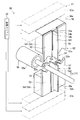
- FIG. 2 is a schematic perspective view showing the electric wire processing apparatus 50 according to the embodiment.
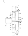
- FIG. 3 is a schematic front view showing the electric wire processing apparatus 50 according to the embodiment.
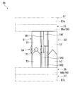
- FIG. 4 is a schematic side view showing the electric wire processing apparatus 50 according to the embodiment.
- the electric wire processing apparatus 50 includes processing blade units 51 and 52 and a shift mechanism 55. Further, here, the electric wire processing apparatus 50 includes a processing blade moving mechanism 57, a partition 58, and a vacuum mechanism 59.
- the processing blade units 51 and 52 are portions that contact the electric wire 12 and perform processing. A plurality (two in this case) of processing blade units 51 and 52 are provided. The two processing blade units 51 and 52 are provided so as to be selectively switched every time the electric wire 12 is processed. In the following description, it is assumed that the machining blade unit 51 is for the copper electric wire 12a and the machining blade unit 52 is for the aluminum electric wire 12b.
- the processing blade units 51 and 52 include a pair of processing blades 53 here.
- a pair of processing blades 53 sandwiches the electric wire 12 and performs processing.
- the pair of processing blades 53 are provided so as to be movable toward and away from each other by a processing blade moving mechanism 57.
- Each processing blade 53 has a recess 53a.
- the pair of processing blades 53 are disposed so as to be shifted in the extending direction of the electric wire 12. Then, the pair of processing blades 53 approach each other with the concave portion 53a facing the electric wire 12 side, and process (cut here) the electric wire 12 so as to be sandwiched so that the electric wire 12 is accommodated in the concave portion 53a.
- the processing blade 53 is attached to the attachment portion 54.
- one of the pair of processing blades 53 is attached to the attachment portion 541, and the other of the pair of processing blades 53 is attached to the attachment portion 542.
- the wire processing device 50 is the tip cut unit 50.
- a plurality of cutting blade units for cutting the electric wire 12 are provided as the plurality of processing blade units 51 and 52.
- the two processing blade units 51 and 52 are cutting blade units 51 and 52 including a cutting blade as the processing blade 53.
- the cutting blade of the cutting blade unit is formed in a V shape when viewed from the front.
- a plurality of machining blade units formed in the same shape as the plurality of machining blade units 51 and 52 are provided.
- the cutting blade 53 of the cutting blade unit 51 is formed in the same shape as the cutting blade 53 of the cutting blade unit 52.
- the mounting portion 54 is formed in a substantially rectangular parallelepiped shape.
- the machining blade 53 is attached to one attachment surface of the attachment portion 54 in a shifted manner (here, at an interval).
- a stepped portion 54a is provided on the mounting surface 54s.
- the partition 58 is provided between the plurality of processing blade units 51 and 52.
- the partition 58 suppresses the scattered chips from entering another processing blade unit (for example, the processing blade unit 52).
- the partition 58 is formed in a flat plate shape.
- the partition 58 includes a first partition portion 58a and a second partition portion 58c connected to the first partition portion 58a via a connecting portion 58b, and is formed in an approximately L shape.
- the 1st partition part 58a is a site
- the 2nd partition part 58c is a site
- 1st partition part 58a is a part which protrudes along the extension direction of the electric wire 12 from the said convex part 54b of the attaching part 54. As shown in FIG.
- the second partition portion 58 c is a portion that protrudes from the surface of the attachment portion 54 that faces the other attachment portion 54 toward the other attachment portion 54.
- the partition 58 is provided in each of the pair of attachment portions 541 and 542.
- the partition 581 provided in the attachment part 541 and the partition 582 provided in the attachment part 542 are provided at intervals along the shift direction of the machining blade units 51 and 52.
- the shift mechanism 55 shifts the plurality of processing blade units 51 and 52 so as to be selectively arranged with respect to the processing position.
- the shift mechanism 55 includes a linear actuator 56 such as an air cylinder or a linear motor.
- the shift mechanism 55 includes linear actuators 56a and 56b that shift the attachment portions 541 and 542, respectively.
- the linear actuators 56a and 56b move the mounting portions 541 and 542 so that one of the two processing blade units 51 and 52 is at the processing position.
- the machining blade unit 51 is located at the machining position
- FIG. 7 the machining blade unit 52 is located at the machining position.
- the working blade moving mechanism 57 is provided so that the pair of working blades 53 can be moved closer to and away from each other. By moving the pair of processing blades 53 closer, the electric wire 12 positioned between the pair of processing blades 53 can be processed. Further, by moving the pair of processing blades 53 apart, the electric wire 12 to be processed can be taken in between the pair of processing blades 53.
- the processing blade moving mechanism 57 will be described as moving the two processing blade units 51 and 52 at the same time, but this is not essential.
- the processing blade moving mechanism may move the processing blade units 51 and 52 separately. In this case, the processing blade moving mechanism may move the processing blade units 51 and 52 separately by two driving units, or may move the processing blade units 51 and 52 separately by one driving unit. . However, since the processing blade moving mechanism 57 moves the two processing blade units 51 and 52 simultaneously, the processing blade units 51 and 52 can be moved with a simple configuration by a single drive unit.
- the processing blade moving mechanism 57 includes linear actuators 57a and 57b such as an air cylinder or a linear motor. More specifically, the linear actuator 57 a moves the attachment portion 541 toward the attachment portion 542. The linear actuator 57b moves the attachment portion 542 toward the attachment portion 541. Here, the linear actuators 57 a and 57 b move the attachment portion 54 together with the shift mechanism 55.
- 3 and 7 are diagrams in which the processing blade 53 has moved closer. 4 and 8 are views in which the machining blade 53 is moved away from each other.
- the vacuum mechanism 59 sucks chips so as to reduce the amount of chips (including the cut end portion or the peeled portion of the wires 12) scattered when the electric wire 12 is processed by the processing blade units 51 and 52. It is made possible.
- the vacuum mechanism 59 includes a suction unit 59a and an ejector.
- the suction part 59a includes a suction port for sucking chips and constitutes a path along which the sucked chips move.
- the suction port of the suction part 59a is formed in a substantially cylindrical shape.
- the suction port is fixed prior to the tip of the electric wire 12 with respect to the apparatus, and the position where the suction port is located is the processing position when the shift mechanism 55 shifts the processing blade units 51 and 52 (see FIG. 3 and FIG. 3). (See FIG. 4).
- the ejector is provided so that the gas in the suction part 59a can be discharged so that the suction part 59a can suck chips.
- FIG. 9 is a schematic front view showing another electric wire processing apparatus 60 according to the embodiment.
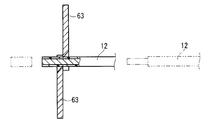
- FIG. 10 is a diagram for explaining how the electric wires 12 are peeled off.
- the same components as those described in the electric wire processing apparatus 50 are denoted by the same reference numerals, and the description thereof is omitted.
- the electric wire processing device 60 is different from the electric wire processing device 50 in that it is provided for skinning as described above.
- the processing blade units 61 and 62 of the electric wire processing apparatus 60 include skinning blade units 61 and 62.
- the skinning blade 63 of the skinning blade unit is formed in a curved shape when viewed from the front.
- the tip portions of the pair of peeling blades 63 are moved close enough to bite into only the covering portion of the electric wire 12, and in this state, the pair of peeling blades 63 are The covering portion is peeled off by moving the wire 12 toward the end side. At this time, the pair of peeling blades 63 may be moved, or the electric wires 12 may be moved.
- the processing blade moving mechanism 57 of the electric wire processing apparatus 60 may include a linear actuator that moves the processing blade 63 along the extending direction of the electric wires 12.
- the 1st electric wire conveyance mechanism 42 contains the linear actuator etc. which move the electric wire holding part 44 along the extension direction of the electric wire 12.
- the peeling blade 63 of the peeling blade unit 61 and the peeling blade 63 of the peeling blade unit 62 are formed in the same shape. For this reason, even if the copper electric wire 12a and the aluminum electric wire 12b which have a comparable diameter are peeled off with the same apparatus, mixing of a dissimilar metal can be suppressed.
- the control unit 80 also performs switching of the processing blades of the electric wire processing apparatuses 50 and 60 and approaching or separating movement of the processing blades.
- control unit 80 is a general microcomputer including a CPU, a ROM, a RAM, and the like, and controls the operation of the cutting device 20 in accordance with a software program stored in advance and a predetermined set value.
- control unit 80 instructs the electric wire processing apparatuses 50 and 60 to switch to an appropriate processing blade for the electric wire 12 to be processed next, and performs processing with the switched processing blade. In this way, operation control is performed.
- some or all of the functions performed by the control unit 80 may be realized by hardware using a dedicated logic circuit or the like.
- step S1 the type of the core wire of the electric wire 12 to be processed next is checked.
- the production plan table that has been read or entered is referred to, or the type and order of the electric wires 12 supplied by the electric wire supply unit 22 are stored and referenced. It can be considered.
- step S2 it is determined whether the type of the core wire targeted by the processing blade units 51 and 52 (61, 62) at the current processing position matches the type of the core wire checked in step S1. If they match, the process proceeds to step S4, and if they do not match, the process proceeds to step S3.
- step S1 and step S2 may be abbreviate
- Step S2 will be described more specifically using the wire processing apparatus 50.
- the electric wire 12 to be processed is the copper electric wire 12a and the processing blade unit at the current processing position is the processing blade unit 51
- the electric wire 12 to be processed next is the aluminum electric wire 12b and the processing blade at the current processing position. If the unit is the machining blade unit 52, YES is returned in step S2. Further, when the electric wire 12 to be processed next is the copper electric wire 12a and the processing blade unit at the current processing position is the processing blade unit 52, and the electric wire 12 to be processed next is the aluminum electric wire 12b and is at the current processing position.
- NO is returned in step S2.
- a command is issued to the shift mechanism 55 to switch the machining blade units 51, 52 (61, 62).
- the processing blade unit at the current processing position for example, the processing blade unit in FIG. 3
- 51 is commanded to switch to the other processing blade unit (for example, the processing blade unit 52 in FIG. 3).
- the shift mechanism 55 moves the processing blade units 51 and 52, so that the electric wire processing apparatus 50 is suitable for the electric wire 12 to be processed next in the posture shown in FIG. 3 or the posture shown in FIG. Take posture.
- the processing blade unit 51 is positioned at the processing position, and when the electric wire 12 to be processed next is the aluminum electric wire 12b, the processing blade unit 52 is at the processing position. Located in. The same applies to the electric wire processing apparatus 60.
- the electric wire 12 to be processed next is received at the processing position to prepare a state capable of processing.
- the control unit 80 issues a movement command to the first wire conveying mechanism 42 that moves the wire gripping portion 44 that grips the end of the wire 12 to be processed next.
- the 1st electric wire conveyance mechanism 42 moves the electric wire holding part 44 to a predetermined position with respect to the electric wire processing apparatus 50 (60), and the electric wire 12 processed next becomes the electric wire processing apparatus 50 (60). On the other hand, it moves to the processing position.
- step S4 the movement of the wire gripping portion 44 in step S4 is part of the movement in which the first wire transport mechanism 42 circulates the wire gripping portion 44. For this reason, while it is repeatedly processed by the electric wire processing apparatus 50 (60), the previously processed electric wire 12 is directed to the next processing position P2b or P3 by the first electric wire transport mechanism 42 in step S4. Sent.
- the control unit 80 instructs the electric wire processing apparatus 50 (60) to process the electric wire 12.
- the electric wire processing apparatus 50 (60) processes the electric wire 12 by the processing blade units 51 and 52 (61 and 62) at the current processing position.
- the tip of the electric wire 12 is cut.
- the control unit 80 issues a command to move away from the machining blade moving mechanism 57 and then move away.
- the machining blade moving mechanism 57 moves the machining blade 53 closer, whereby the electric wire 12 is cut.
- the electric wire 12 is cut by one of the processing blade units 51 and 52 selected in steps S1 to S3 (see FIGS. 5 and 8).
- the machining blade moving mechanism 57 moves the machining blade 53 away from each other after the wire 12 is cut, the next wire 12 can be received when the process proceeds to step S4 again during repeated machining.
- the control unit 80 issues a command to move away from the machining blade moving mechanism 57 and then move away. Further, here, the control unit 80 moves the processing blade 63 along the extending direction of the electric wire 12 in the state where the processing blade moving mechanism 57 of the electric wire processing device 60 moves the processing blade 63 closer to the end side of the electric wire 12. Command to move relative to. In response to this, the processing blade moving mechanism 57 moves the processing blade 63 closer, and the processing blade 63 moves relative to the end of the electric wire 12 along the extending direction of the electric wire 12, so that the electric wire 12 is peeled off. Stripped. Here, the electric wire 12 is stripped by one of the processing blade units 61 and 62 selected in steps S1 to S3.
- next step S6 it is determined whether the production is finished. The determination may be made in light of the production plan table or the like, or may be made in light of the number of wires supplied from the wire supply unit 22. If it is determined that the production is finished, the machining by the electric wire machining apparatus 50 (60) is finished. If it is not determined that the production is finished, the process returns to step S1, and the processing is repeated until the production is finished.
- the plurality of processing blade units 51 and 52 and the shift mechanism 55 that shifts the plurality of processing blade units 51 and 52 so as to be selectively arranged with respect to the processing position. Therefore, the machining blade units 51 and 52 can be switched for each material of the core wire. As a result, even if processing is performed with chips and the like attached to the processing blade units 51 and 52, the processing blade units 51 and 52 are designed exclusively for each material, so that mixing of dissimilar metals is suppressed. Can do. Accordingly, when a plurality of types of electric wires 12 having different core wire materials are processed using the processing blade 53, mixing of dissimilar metals can be suppressed.
- the processing blade units 51 and 52 include a pair of processing blades 53 that sandwich and process the electric wire 12, and further include a processing blade moving mechanism 57 that relatively moves the pair of processing blades 53 toward or away from each other, and a shift mechanism. 55 moves the processing blade units 51 and 52 for each material of the core wire with a simple configuration in order to move the processing blade units 51 and 52 in a direction crossing the extending direction of the electric wire 12 set at the processing position. Can do.
- the processing blade units 51 and 52 include a plurality of cutting blade units that cut the electric wire 12, the processing blade units 51 and 52 are switched for each core wire material even in a cutting process in which chips are likely to be generated. Can do.
- the processing blade units 51 and 52 include a plurality of processing blade units 51 and 52 that are formed in the same shape, the processing blade units 51 and 52 for each core wire material with respect to the electric wire 12 having the same diameter. 52 can be switched.
- the core wire processed by one processing blade unit for example, the processing blade unit 51. It is possible to prevent chips from scattering and adhering to another processing blade unit (for example, the processing blade unit 52).
- the electric wire processing apparatus 50 it has been described that the two processing blade units 51 and 52 are provided, but this is not essential.
- the electric wire processing apparatus may be provided with three or more processing blade units. The same applies to the electric wire processing apparatus 60.
- the cutting blade is formed in a V shape in front view and the peeling blade is formed in a curved shape in front view, this is not essential.
- the shapes of the cutting blade and the skinning blade may be reversed, for example, as long as they are set appropriately.
- processing blade moving mechanism 57 has been described as moving the pair of processing blades 53 toward the other processing blade, this is not essential.
- the processing blade moving mechanism may move only one of the pair of processing blades 53 toward the other processing blade.
- the electric wire processing apparatus 50 was demonstrated as what was integrated in the cutting pressure apparatus 20 in embodiment, this is not essential.
- the wire processing device 50 may be used alone or may be incorporated in a device other than the cutting pressure device 20. The same applies to the electric wire processing apparatus 60. Further, the electric wire processing device 50 may be employed in the cutting mechanism 28 of the cutting pressure device 20.
Landscapes
- Life Sciences & Earth Sciences (AREA)
- Forests & Forestry (AREA)
- Engineering & Computer Science (AREA)
- Mechanical Engineering (AREA)
- Removal Of Insulation Or Armoring From Wires Or Cables (AREA)
Abstract
本発明は、芯線の材料が異なる複数種類の電線を、加工刃を用いて加工する際に、異種金属の混入を抑制することができる技術を提供することを目的とする。電線加工装置は、電線に対して刃物を当てて加工する電線加工装置である。電線加工装置は、複数の加工刃ユニットと、前記複数の加工刃ユニットを加工位置に対して選択的に配置するようにシフトさせるシフト機構と、を備える。電線加工装置は、前記複数の加工刃ユニットの間に設けられ、飛散する切屑の侵入を抑制する仕切をさらに備えることが考えられる。
Description
この発明は、電線の切断又は皮剥ぎ等を行うための技術に関する。
ワイヤーハーネスの製造には電線の切断又は皮剥ぎの工程が存在する。電線を切断する技術として、例えば、特許文献1に開示のものがある。
特許文献1に記載の切断刃ユニットは、芯線と、該芯線を被う絶縁被覆と、該絶縁被覆を被う金属箔と、を含む電線をテーパ面に押し当てることによって押し返された絶縁被覆の反発力を利用して金属箔を切断するものである。
ところで、電線には、銅電線又はアルミニウム電線等、芯線の材料が異なる電線がある。この場合、芯線の材料が異なる複数種類の電線を同じ加工刃で加工すると、ある材料の切屑が別の材料の芯線に付着するなどして異種金属が混入する恐れがある。そして、このように異種金属が混入すると腐食につながる恐れがある。
このような事態を避けるためには、芯線の材料ごとに別の装置で製造することが考えられる。この場合、装置の数が増えることで、コストがかかると共に空間的規制が大きくなってしまう恐れがある。
そこで、本発明は、芯線の材料が異なる複数種類の電線を、加工刃を用いて加工する際に、異種金属の混入をより簡易に抑制することができる技術を提供することを目的とする。
上記課題を解決するため、第1の態様に係る電線加工装置は、電線に対して刃物を当てて加工する電線加工装置であって、複数の加工刃ユニットと、前記複数の加工刃ユニットを加工位置に対して選択的に配置するようにシフトさせるシフト機構と、を備える。
第2の態様に係る電線加工装置は、第1の態様に係る電線加工装置であって、前記加工刃ユニットは、電線を挟み込んで加工する一対の加工刃を含み、前記一対の加工刃を相対的に接近又は離隔移動させる加工刃移動機構をさらに備え、前記シフト機構は、前記加工刃ユニットを、加工位置にセットされた電線の延在方向と交差する方向に移動させる。
第3の態様に係る電線加工装置は、第1又は第2の態様に係る電線加工装置であって、前記複数の加工刃ユニットとして、前記電線を切断する切断刃ユニットを複数備える。
第4の態様に係る電線加工装置は、第1から第3のいずれか1つの態様に係る電線加工装置であって、前記複数の加工刃ユニットとして同形状に形成されている加工刃ユニットを複数備える。
第5の態様に係る電線加工装置は、第1から第4のいずれか1つの態様に係る電線加工装置であって、前記複数の加工刃ユニットの間に設けられ、飛散する切屑の侵入を抑制する仕切をさらに備える。
第1から第5の態様に係る電線加工装置によると、複数の加工刃ユニットと、複数の加工刃ユニットを加工位置に対して選択的に配置するようにシフトさせるシフト機構と、を備えるため、芯線の材料ごとに加工刃ユニットを切り替えることができる。これにより、芯線の材料が異なる複数種類の電線を、加工刃を用いて加工する際に、異種金属の混入を抑制することができる。
特に、第2の態様に係る電線加工装置によると、加工刃ユニットは、電線を挟み込んで加工する一対の加工刃を含み、一対の加工刃を相対的に接近又は離隔移動させる加工刃移動機構をさらに備え、シフト機構は、加工刃ユニットを、加工位置にセットされた電線の延在方向と交差する方向に移動させるため、簡易な構成で芯線の材料ごとに加工刃ユニットを切り替えることができる。
特に、第3の態様に係る電線加工装置によると、複数の加工刃ユニットは、電線を切断する切断刃ユニットを複数備えるため、特に切屑が発生しやすい切断工程についても、芯線の材料ごとに加工刃ユニットを切り替えることができる。
特に、第4の態様に係る電線加工装置によると、複数の加工刃ユニットは、同形状に形成されている加工刃ユニットを複数備えるため、径が同程度の電線に対して芯線の材料ごとに加工刃ユニットを切り替えることができる。
特に、第5の態様に係る電線加工装置によると、複数の加工刃ユニットの間に設けられ、飛散する切屑の侵入を抑制する仕切をさらに備えるため、1つの加工刃ユニットにより加工された芯線の切屑が飛散して別の加工刃ユニットに付着することを抑制することができる。
{実施形態}
以下、実施形態に係る電線加工装置について説明する。実施形態に係る電線加工装置は、電線12に対して刃物を当てて加工する電線加工装置である。ここでは、電線加工装置は、長尺の電線12を加工して端子付電線10を製造する切圧装置20に組み込まれているものとして説明する。
以下、実施形態に係る電線加工装置について説明する。実施形態に係る電線加工装置は、電線12に対して刃物を当てて加工する電線加工装置である。ここでは、電線加工装置は、長尺の電線12を加工して端子付電線10を製造する切圧装置20に組み込まれているものとして説明する。
<切圧装置の全体構成>
ここで、便宜上、切圧装置20について先に説明する。図1は、実施形態に係る電線加工装置を含む切圧装置20を示す概念図である。
ここで、便宜上、切圧装置20について先に説明する。図1は、実施形態に係る電線加工装置を含む切圧装置20を示す概念図である。
この切圧装置20は、長尺な電線12を所定長に切断し、所定長に切断された電線12の両端部の被覆部を皮剥ぎし、その両端部に露出した各芯線に端子を圧着して、端子付電線10を製造する装置である。なお、電線12の一方側の端部のみに端子が圧着されてもよい。また、電線12をゴム栓に通す処理等、他の処理が行われてもよい。
ここでは、切圧装置20は、ワイヤーハーネスの単位ごとに当該ワイヤーハーネスに含まれる複数種類の端子付電線10を1つの装置でまとめて製造する製造方法に供される装置であるものとして説明する。このような製造方法は、セット工法と称されることがある。
このセット工法では、ワイヤーハーネスによっては、芯線の材料が異なる電線12を1つの装置で製造する場合がある。その場合、芯線の材料が異なる電線12に対して同じ加工刃を用いて加工すると、ある電線12を加工した際の切屑が、加工刃を介して芯線の材料が異なる別の電線12に付着する恐れが生じる。このような事態を避けるために、当該切圧装置20に、実施形態に係る電線加工装置が組み込まれている。
具体的には、切圧装置20は、電線供給部22と、調尺送出機構24と、切断機構28と、電線受渡機構30と、電線搬送機構40と、端部加工ユニット50、60、70とを備える。ここでは、端部加工ユニット50、60が実施形態に係る電線加工装置50、60であるものとして説明する。
電線供給部22は、長尺な電線12を連続的に供給可能に構成されている。ここでは、長尺な電線12は、輪状に束ねられており、その束11から長尺な電線12の一端部を引出すことで、長尺な電線12が連続的に供給されるようになっている。なお、長尺な電線12は、電線収容リール等に巻回収容されており、当該電線収容リールから供給されるものであってもよい。ここでは、上記セット工法において、芯線の材料が異なる2つの電線12a、12bがそれぞれ輪状に束ねられている。そして、電線供給部22は、電線12a、12bのうち一方を選択可能であり、選択した電線12を供給可能に設けられている。なお、電線供給部22が供給する電線12を切り替える動作は、後述する制御ユニット80により制御される。以下では、当該切圧装置20で取り扱う電線12のうち、電線12aが芯線が銅を材料として形成された銅電線12aであり、電線12bが芯線がアルミニウムを材料として形成されたアルミ電線12bであるものとして説明する。もっとも、芯線を構成する材料は上記したものに限られず、例えば、ステンレス等であってもよい。
調尺送出機構24は、前記電線供給部22からの電線12を調尺しつつ送出し可能に構成されている。より具体的には、調尺送出機構24は、送出機構25と、調尺部26とを備えている。
送出機構25は、例えば、電線12を挟込む一対の送出ローラ25aと、当該送出ローラ25aの少なくとも一方を回転駆動するモータ等の回転駆動部25b等を含む。そして、前記回転駆動部25bによって送出ローラ25aを回転させることで、電線供給部22から電線12が引出され、その前方に送出される。なお、送出機構25の動作は、制御ユニット80によって制御される。
調尺部26は、電線12を挟込む一対の調尺ローラ26aと、当該調尺ローラ26aの少なくとも一方の回転軸部に連結されたロータリーエンコーダ等の回転量検出部26bとを含む。ここでは、調尺部26は、上記送出機構25よりも上流側(電線供給部22側)に設けられている。調尺部26は、上記送出機構25よりも下流側に設けられていてもよい。そして、電線12が送出される際に、一対の調尺ローラ26aが当該電線12の引出に伴って従動回転すると、その回転量が回転量検出部26bによって検出される。この回転量検出部26bからの回転量検出信号は、制御ユニット80に与えられる。
なお、調尺送出機構24には、複数のローラが交互に配設されたストレーナが組込まれている。電線12が本ストレーナを通ることで、ある程度曲げ癖が除去される。
切断機構28は、調尺送出機構24より送出された電線12を切断可能に構成されている。ここでは、切断機構28は、調尺送出機構24より送出された電線12を挟込み可能な一対の切断刃29と、当該一対の切断刃29を接近及び遠ざける方向に移動させる進退駆動部とを含む。一対の切断刃29の先端部は、V字状に切込む刃形状に形成されている。そして、制御ユニット80からの指令に応じて、上記調尺送出機構24によって製造対象となる端子付電線10の長さに応じた長さの電線12が送出された時点で、一対の切断刃29が接近移動することで、電線12が所定長に切断される。
電線受渡機構30は、上記調尺送出機構24より送出されて、切断機構28によって切断される所定長の電線12を受取位置P1にて電線搬送機構40に受渡可能な姿勢に姿勢変更するように構成されている。具体的には、電線受渡機構30は、旋回チャック31と、捩チャック35とを備えている。
旋回チャック31は、調尺送出機構24より送出される電線12の端部を把持して捩チャック35に受渡すように構成されている。旋回チャック31は、受取位置P1aに対応する位置と受取位置P1bに対応する位置とを往復移動可能に設けられている。
より具体的には、旋回チャック31は、受渡用把持部32と、受渡用把持部移動機構34とを備えている。
受渡用把持部32は、ソレノイドを利用した電磁チャック又はエアシリンダを利用したチャック等によって構成されており、一対の把持爪が開閉駆動されることで、電線12の端部を把持及び把持解除可能に構成されている。
受渡用把持部移動機構34は、上記受渡用把持部32を、調尺送出機構24から切断機構28を通過して送出される電線12の先端部を把持する位置P1aから捩チャック35に対向する位置P1bの間で往復移動させるように構成されている。この際、受渡用把持部移動機構34は、受渡用把持部32を旋回させて移動させる。これにより、捩チャック35に向けて旋回した受渡用把持部32によって把持される電線12の端部が捩チャック35側を向く。このような受渡用把持部移動機構34は、例えば、モータ等によって構成される回転駆動部と、当該回転駆動部により回動する旋回アームとを備えている構成が考えられる。
上記旋回チャック31は、次のようにして電線12の端部の受渡しを行う。すなわち、受渡用把持部32を位置P1aに配設した状態で、調尺送出機構24より電線12が送出される。そして、電線12の端部が受渡用把持部32の一対の把持爪間を越えるまで、電線12が送出されると、電線12の送出しが停止される。この状態で、一対の把持爪が閉じられ、受渡用把持部32によって電線12の端部が把持される。
この後、受渡用把持部移動機構34によって受渡用把持部32を位置P1bに回転移動させ、捩チャック35に対向する位置に配置する。なお、旋回チャックの旋回中、調尺送出機構24は、電線12を引出自在な状態、または、その旋回による電線12の引出速度及び引出量に合わせて電線12を送出す状態となる。
受渡用把持部32が位置P1bに移動した状態では、受渡用把持部32によって把持された電線12の端部は、捩チャック35に向けるように配設され、捩チャック35は当該電線12の端部を把持できるようになる。
捩チャック35は、電線12の端部を把持した状態で、電線12の端部を回転させるように構成されている。ここでは、上記したように輪状にまとめられた束11から電線12を供給する。このため、電線12を所定長に切断し両端を把持した際に、切断した電線12に捩れが残存し、8の字状に捩れる恐れがある。そして、このような電線12が連続的に加工処理されると、排出位置P5では、電線12が8の字状に捩れた状態のまま積重ねられる。この複数の電線12の両端部を一括して引張ると、電線12の中間部に、小さく8の字状に捩れた箇所が生じてしまう。この電線12を用いてワイヤーハーネスを製造する場合には、各電線12に対して小さく8の字状に捩れた箇所を無くす必要がある。場合によっては、電線12の中間部に捩れ癖が残ってしまう恐れもある。捩チャック35は、当該捩れを抑制可能に形成されている。これにより、切圧装置20の以降の工程中に捩れに起因する不良が発生することを抑制することができる。具体的には、捩チャック35は、回転用把持部36と、把持回転駆動部38とを備える。
回転用把持部36は、ソレノイドを利用した電磁チャック又はエアシリンダを利用したチャック等によって構成されており、一対の把持爪が開閉駆動されることで、上記調尺送出機構24より送出され、旋回チャック31によって受渡される電線12の端部を把持及び把持解除可能に構成されている。
把持回転駆動部38は、上記回転用把持部36を回転可能に構成されている。より具体的には、把持回転駆動部38は、モータ等によって構成されており、上記位置P1bであって、回転用把持部36を挟んで旋回チャック31の反対側の位置に設けられている。この取付状態で、回転用把持部36の先端部は、位置P1b側を向いており、従って、上記受渡用把持部32が位置P1bに移動すると、当該受渡用把持部32より突出する電線12の端部が回転用把持部の一対の把持爪間に配設され、この状態で、当該一対の把持爪を閉じると、当該電線12の端部が当該一対の把持爪によって把持されるようになっている。また、この状態で、把持回転駆動部38の駆動により回転用把持部36を回転させると、これに伴い、電線12の端部が回転されるようになっている。なお、把持回転駆動部38には、エンコーダ等が組込まれており、回転数を示す信号が制御ユニット80に与えられる。
上記旋回チャック31及び捩チャック35は、いずれも制御ユニット80によって動作制御される。
電線搬送機構40は、上記調尺送出機構24より送出されて、切断機構28によって切断された所定長の電線12の両端部を把持して、当該所定長の電線12を、所定の搬送方向Pに沿って、調尺送出機構24による受取位置P1から端部加工ユニット50、60、70による各加工位置P2a、P2b、P3、排出用受渡位置P4を経て所定の排出位置P5に向けて搬送するように構成されている。
より具体的には、電線搬送機構40は、第1電線搬送機構42と、第2電線搬送機構46とを備えている。
第1電線搬送機構42は、電線12を、上記受取位置P1から、加工位置P2a、P2b、P3を経て排出用受渡位置P4に向けて搬送する装置であり、第2電線搬送機構46は、電線12を排出用受渡位置P4から排出位置P5に向けて搬送する装置である。
第1電線搬送機構42は、複数の電線把持部44を備えている。複数の電線把持部44は、上記受取位置P1、加工位置P2a、P2b、P3及び排出用受渡位置P4を通るように配設された搬送用循環ベルトに間隔をあけて取付けられている。搬送用循環ベルトは、受取位置P1、加工位置P2a、P2b、P3及び排出用受渡位置P4を通る搬送方向Pの両端部に設けられた一対の回転用プーリー又は一対の歯車に巻掛けられており、当該回転用プーリー又は歯車をモータ等の回転駆動部によって回転させることで、搬送用循環ベルトが、受取位置P1、加工位置P2a、P2b、P3及び排出用受渡位置P4を通って循環回転する。各電線把持部44は、ソレノイドを利用した電磁チャック又はエアシリンダを利用したチャック等によって構成されており、一対の把持爪が開閉駆動されることで、電線12の端部を把持及び把持解除可能に構成されている。
そして、上記搬送用循環ベルトの循環回転によって複数の電線把持部44が、受取位置P1、加工位置P2a、P2b、P3及び排出用受渡位置P4を通るように移動すると共に、各位置P1、P2a、P2b、P3,P4で、各電線把持部44が適宜開閉して電線12の把持及び把持解除動作を行うことで、電線12の受取り、搬送、排出、さらに、電線12の端部に対する加工処理が施される。
ここでは、複数の電線把持部44のうち一対の電線把持部44の一方が、調尺送出機構24及び切断機構28による送出し位置である受取位置P1aに位置すると共に、一対の電線把持部44の他方がその下流側の受取位置P1bに位置した状態で、調尺送出機構24及び切断機構28から送出された電線12の両端部が当該一対の電線把持部44により把持されて所定長に切断される。この状態では、所定長の電線12の中間部は、調尺送出機構24及び切断機構28の反対側にU字状に垂下がっている。所定長の電線12は、両端部が一対の電線把持部44により把持されてその中間部がU字状に垂下がった状態で搬送される。
本電線搬送機構40による各電線把持部44の送り動作及び各電線把持部44の把持及び把持解除動作の制御も、制御ユニット80からの指令に応じてなされる。
ここでは、次のように搬送動作を行う。すなわち、一対の電線把持部44が、受取位置P1にて、所定長の電線12の両端部を把持した状態で、搬送方向Pに沿って移動し、加工位置P2aに移動すると、その両端部が端部加工ユニット50に向けられる。この状態で、端部加工ユニット50による端部加工処理がなされる。続けて加工位置P2bにおいて、端部加工ユニット60による端部加工処理がなされる。さらに、一対の電線把持部44が加工位置P3に移動すると、その両端部が端部加工ユニット70に向けられる。この状態で、端部加工ユニット70による端部加工処理がなされる。
この後、一対の電線把持部44が搬送方向Pに沿って排出用受渡位置P4に移動する。
第2電線搬送機構46は、一対の排出受渡用把持部47と、受渡用往復駆動部48とを備えている。一対の排出受渡用把持部47は、ソレノイドを利用した電磁チャック又はエアシリンダを利用したチャック等によって構成されており、一対の把持爪が開閉駆動されることで、電線12の端部を把持及び把持解除可能に構成されている。受渡用往復駆動部48は、エアシリンダ又はリニアモータ等のリニアアクチュエータ等によって構成されており、上記一対の排出受渡用把持部47を、排出用受渡位置P4と排出位置P5との間で往復駆動させる。
ここで、排出位置P5には、例えば、電線12の端部を保持可能な保持部が複数形成された電線保持バー90が配設されている。そして、一対の電線把持部44が排出用受渡位置P4に移動すると、その一対の電線把持部44によって把持された電線12の両端部が、一対の排出受渡用把持部47によって把持される。この後、受渡用往復駆動部48の駆動によって、一対の排出受渡用把持部47が排出用受渡位置P4から排出位置P5に移動して、電線12の両端部を電線保持バー90の保持部に選択的に受け渡す。
上記処理が連続的に行われることで、複数の端子付電線10が連続的に製造され、また、連続的に製造された端子付電線10は、第2電線搬送機構46によって、電線保持バー90に移し替えられる。電線保持バー90に所定数の端子付電線10が移し替えられると、作業者による人手等によって、電線保持バー90ごと保管及び次のワイヤーハーネス製造現場への搬送等が行われる。
端部加工ユニット50、60、70は、長尺の電線12より切断された所定長の電線12の端部に対して端部加工処理を施すユニットである。
ここでは、端部加工ユニット50が先端カットユニット50であり、端部加工ユニット60が皮剥ユニット60であり、端部加工ユニット70が端子圧着ユニット70である場合を想定している。
先端カットユニット50は、電線調尺長さをそろえるために上記調尺部26で調尺されると共に切断機構28で切断された後の電線12の先端をカットして、狙いの長さにそろえる加工を行うユニットである。
皮剥ユニット60は、電線12の端部の被覆部を皮剥して、当該端部に芯線部を露出させる加工を行うユニットであり、電線12の搬送方向Pにおいて、上記先端カットユニット50の下流側に設けられている。
端子圧着ユニット70は、電線12の端部に露出する芯線に端子を圧着するためのユニットであり、電線12の搬送方向Pにおいて、上記皮剥ユニット60の下流側に設けられている。端子圧着ユニット70は、電線12の両端に対して端子を圧着するものであっても、一端のみに端子を圧着するものであってもよい。
なお、端部加工ユニットの例は上記に限られず、電線12の端部に対して加工を行う各種端部加工装置を用いることができる。
ここでは、上記先端カットユニット50が実施形態に係る電線加工装置50である。また、上記皮剥ユニット60が電線加工装置50とは、別の電線加工装置60である。
<電線加工装置50(先端カットユニット)>
電線加工装置50について詳述する。図2は、実施形態に係る電線加工装置50を示す概略斜視図である。図3は、実施形態に係る電線加工装置50を示す概略正面図である。図4は、実施形態に係る電線加工装置50を示す概略側面図である。
電線加工装置50について詳述する。図2は、実施形態に係る電線加工装置50を示す概略斜視図である。図3は、実施形態に係る電線加工装置50を示す概略正面図である。図4は、実施形態に係る電線加工装置50を示す概略側面図である。
電線加工装置50は、加工刃ユニット51,52と、シフト機構55とを備える。さらにここでは、電線加工装置50は、加工刃移動機構57と仕切58とバキューム機構59とを備える。
加工刃ユニット51,52は、電線12に当接して加工処理を行う部分である。加工刃ユニット51,52は、複数(ここでは、2つ)設けられている。2つの加工刃ユニット51,52は、電線12を加工する毎に選択的に切替え可能に設けられている。以下では、加工刃ユニット51が銅電線12a用であり、加工刃ユニット52がアルミ電線12b用であるものとして説明する。
具体的には、ここでは、加工刃ユニット51,52は、一対の加工刃53を含む。一対の加工刃53が電線12を挟み込んで加工を施す。一対の加工刃53は、加工刃移動機構57により接近及び離隔移動可能に設けられている。それぞれの加工刃53には凹部53aが形成されている。また、一対の加工刃53は、電線12の延在方向にずらして配設される。そして、一対の加工刃53はそれぞれ凹部53aを電線12側に向けた状態で接近していき、凹部53aに電線12を収めるように挟み込むようにして電線12を加工(ここでは、切断)する。加工刃53は、取付部54に取り付けられる。ここでは、一対の加工刃53のうち一方は、取付部541に取り付けられ、一対の加工刃53のうち他方は、取付部542に取り付けられている。
上記したように、電線加工装置50は、先端カットユニット50である。このため、ここでは、複数の加工刃ユニット51,52として、電線12を切断する切断刃ユニットを複数備える。ここでは、2つの加工刃ユニット51,52が、加工刃53として切断刃を含む切断刃ユニット51,52となっている。ここでは切断刃ユニットの切断刃は、正面視V字状に形成されている。
また、ここでは、複数の加工刃ユニット51,52として同形状に形成されている加工刃ユニットを複数備える。具体的には、切断刃ユニット51の切断刃53は、切断刃ユニット52の切断刃53と同形状に形成されている。このため、同程度の径を有する銅電線12aとアルミ電線12bとを同じ装置で切断しても、異種金属の混合を抑制することができる。
取付部54は、略直方体状に形成されている。取付部54の1つの取付面に加工刃53がずらして(ここでは、間隔をあけて)取り付けられている。取付面54sには段差部54aが設けられている。当該段差部54aが設けられることで、取付面54sに加工刃53を取り付けるに当たり、加工刃53の位置決めをしやすくなる。そして、段差部54aが設けられることにより、取付面54sのうち加工刃53の間の部分には、外方に出っ張る凸部54bが形成されている。
仕切58は、複数の加工刃ユニット51,52の間に設けられている。仕切58は、1つの加工刃ユニット(例えば、加工刃ユニット51)で電線12を加工した際に、飛散する切屑が別の加工刃ユニット(例えば、加工刃ユニット52)に侵入することを抑制する。仕切58は、平板状に形成されている。ここでは、仕切58は、第1仕切部58aと、第1仕切部58aに連結部58bを介して連なる第2仕切部58cとを含み、略L字状に形成されている。第1仕切部58aは、例えば、誤った刃物側へ電線12が移動しないように遮るための部位である。また、例えば、第2仕切部58cは、切断後の電線屑の飛散を抑止するための部位である。
第1仕切部58aは、取付部54の上記凸部54bから電線12の延在方向に沿って突出する部分である。
第2仕切部58cは、取付部54のうち他方の取付部54を向く面から他方の取付部54に向けて突出する部分である。
また、ここでは、仕切58は、一対の取付部541、542にそれぞれ設けられている。そして、取付部541に設けられた仕切581と、取付部542に設けられた仕切582とは、加工刃ユニット51,52のシフト方向に沿って間隔をあけて設けられている。これにより、一対の加工刃53が接近した際に、仕切581と仕切582とが重なる部分が生じ、一方の加工刃ユニット51,52から他方の加工刃ユニット51,52に向けて飛散する切屑が抜ける間隙をできるだけなくすことができる。
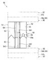
シフト機構55は、複数の加工刃ユニット51,52を加工位置に対して選択的に配置するようにシフトさせる。具体的には、シフト機構55は、エアシリンダ又はリニアモータ等のリニアアクチュエータ56を含む。ここでは、シフト機構55は、取付部541、542をそれぞれシフトさせるリニアアクチュエータ56a、56bを含む。そして、リニアアクチュエータ56a、56bは、2つの加工刃ユニット51、52のいずれか一方が加工位置にくるように、取付部541、542を移動させる。図3では加工刃ユニット51が加工位置に位置し、図7では加工刃ユニット52が加工位置に位置している。
加工刃移動機構57は、一対の加工刃53を接近及び離隔移動可能に設けられている。一対の加工刃53を接近移動させることで、一対の加工刃53の間に位置する電線12を加工することができる。また、一対の加工刃53を離隔移動させることで加工したい電線12を一対の加工刃53の間に取り込むことが可能となる。ここでは、加工刃移動機構57は、2つの加工刃ユニット51,52を同時に移動させるものとして説明するが、このことは必須ではない。加工刃移動機構は、加工刃ユニット51,52を別々に移動させてもよい。この場合、加工刃移動機構は、2つの駆動部で加工刃ユニット51,52を別々に移動させてもよいし、1つの駆動部で、加工刃ユニット51,52を別々に移動させてもよい。しかしながら加工刃移動機構57が2つの加工刃ユニット51,52を同時に移動させることで1つの駆動部で簡易な構成で加工刃ユニット51,52を移動させることができる。
具体的には、加工刃移動機構57は、エアシリンダ又はリニアモータ等のリニアアクチュエータ57a、57bを含む。より具体的には、リニアアクチュエータ57aは、取付部541を取付部542に向けて移動させる。また、リニアアクチュエータ57bは、取付部542を取付部541に向けて移動させる。ここでは、リニアアクチュエータ57a、57bは、取付部54をシフト機構55ごと移動させる。図3及び図7は、加工刃53が接近移動した図である。また、図4及び図8は、加工刃53が離隔移動した図である。
バキューム機構59は、加工刃ユニット51,52により電線12を加工した際に出る切屑等(電線12のうちカットした先端部分又は皮剥ぎ部分等を含む)が飛散する量を削減可能に切屑を吸い込み可能に形成されている。具体的には、バキューム機構59は、吸引部59aと、エジェクタとを備える。
吸引部59aは、切屑を吸い込む吸引口を含み、吸い込んだ切屑が移動する経路を構成する。ここでは、吸引部59aのうち吸引口は略円筒状に形成されている。例えば、吸引口は装置に対して電線12の先端より先に固定され、当該吸引口のある位置が、シフト機構55が加工刃ユニット51,52をシフトさせる際の加工位置となる(図3及び図4参照)。
エジェクタは、吸引部59aが切屑を吸引可能となるように吸引部59a内の気体を排出可能に設けられている。
<電線加工装置60(皮剥ぎユニット)>
電線加工装置60について詳述する。図9は、実施形態に係る別の電線加工装置60を示す概略正面図である。図10は、電線12を皮剥ぎする様子を説明する図である。なお、本電線加工装置60の説明において、電線加工装置50で説明したものと同様構成要素については同一符号を付してその説明を省略する。
電線加工装置60について詳述する。図9は、実施形態に係る別の電線加工装置60を示す概略正面図である。図10は、電線12を皮剥ぎする様子を説明する図である。なお、本電線加工装置60の説明において、電線加工装置50で説明したものと同様構成要素については同一符号を付してその説明を省略する。
電線加工装置60は、上記したように皮剥ぎ用に設けられている点で、電線加工装置50とは異なる。具体的には、電線加工装置60の加工刃ユニット61,62は、皮剥刃ユニット61、62を備える。皮剥刃ユニットの皮剥刃63は、正面視湾曲状に形成されている。
電線加工装置60としては、例えば図10に示すように、一対の皮剥刃63の先端部を、電線12の被覆部のみに食込む程度に接近移動させ、この状態で、一対の皮剥刃63を電線12の端部側に相対移動させることで、被覆部の皮剥がなされる。なお、この際、一対の皮剥刃63を移動させてもよいし、電線12を移動させてもよい。一対の皮剥刃63を移動させる場合には、電線加工装置60の加工刃移動機構57が加工刃63を電線12の延在方向に沿って移動させるリニアアクチュエータ等を含むことが考えられる。また、電線12を移動させる場合には、第1電線搬送機構42が電線把持部44を電線12の延在方向に沿って移動させるリニアアクチュエータ等を含むことが考えられる。
皮剥刃ユニット61の皮剥刃63と皮剥刃ユニット62の皮剥刃63とは、同形状に形成されている。このため、同程度の径を有する銅電線12aとアルミ電線12bとを同じ装置で皮剥ぎしても、異種金属の混合を抑制することができる。
上記電線加工装置50、60の加工刃の切替え及び加工刃の接近又は離隔移動についても、制御ユニット80でなされる。
ここで、制御ユニット80は、CPU、ROMおよびRAM等を備える一般的なマイクロコンピュータであり、予め格納されたソフトウェアプログラム及び所定の設定値に従って切圧装置20の動作制御を行う。特に、ここでは、制御ユニット80は、電線加工装置50、60に、次に加工する電線12に対して適切な加工刃に切り替えるように指令を出したうえで、切り替えた加工刃により加工を施すように、動作制御を行う。なお、制御ユニット80が行う処理の一部或は全部の機能が、専用の論理回路等でハードウエア的に実現されてもよい。
<動作>
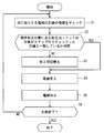
続いて電線加工装置50(60)の動作例について図11に示されるフローチャートを参照しつつ説明する。
続いて電線加工装置50(60)の動作例について図11に示されるフローチャートを参照しつつ説明する。
まずは、ステップS1で、次に加工する電線12の芯線の種類をチェックする。電線12の芯線の種類をチェックするには、読み込み又は入力等がなされた生産計画表等を参照する又は電線供給部22により供給される電線12の種類と順番等を記憶しておきそれを参照する等が考えられる。
次のステップS2では、現在加工位置にある加工刃ユニット51,52(61,62)が対象としている芯線の種類が、上記ステップS1でチェックした芯線の種類と一致しているかを判定する。もし、一致していればステップS4に進み、一致していなければステップS3に進む。なお、電線加工装置50の下流側に配設される電線加工装置60においては、電線加工装置50に合わせることで、ステップS1とステップS2とが省略されてもよい。
ステップS2について電線加工装置50を用いてより具体的に説明する。次に加工する電線12が銅電線12aであり現在加工位置にある加工刃ユニットが加工刃ユニット51である場合、及び、次に加工する電線12がアルミ電線12bであり現在加工位置にある加工刃ユニットが加工刃ユニット52である場合には、当該ステップS2においてYESと返す。また、次に加工する電線12が銅電線12aであり現在加工位置にある加工刃ユニットが加工刃ユニット52である場合、及び、次に加工する電線12がアルミ電線12bであり現在加工位置にある加工刃ユニットが加工刃ユニット51である場合には、当該ステップS2においてNOと返す。
次ステップS3では、加工刃ユニット51,52(61,62)を切り替えるようにシフト機構55に指令を出す。ここでは、電線加工装置50(60)において、設けられている加工刃ユニット51,52(61,62)は2つなので、現在加工位置にある加工刃ユニット(例えば、図3では、加工刃ユニット51)に対してもう一方の加工刃ユニット(例えば図3では、加工刃ユニット52)に切り替えるように、指令を出す。これを受けてシフト機構55が加工刃ユニット51,52を移動させることにより、電線加工装置50は、図3に示す姿勢又は図7に示す姿勢のうち次に加工する電線12に対して適切な姿勢を取る。これにより、次に加工する電線12が銅電線12aの場合には加工刃ユニット51が加工位置に位置し、次に加工する電線12がアルミ電線12bである場合には加工刃ユニット52が加工位置に位置する。電線加工装置60においても同様である。
次ステップS4では、次に加工する電線12を加工位置に受け入れ、加工可能な態勢を整える。ここでは、制御ユニット80は、次に加工する電線12の端部を把持する電線把持部44を移動させる第1電線搬送機構42に対して移動指令を出す。これを受けて第1電線搬送機構42が電線把持部44を電線加工装置50(60)に対して所定の位置に移動させることで、次に加工する電線12が電線加工装置50(60)に対して加工位置に移動する。
なお、ステップS4における電線把持部44の移動は、第1電線搬送機構42が電線把持部44を循環させる移動の一環である。このため、電線加工装置50(60)により繰り返し加工が行われている間においては、前回加工した電線12は、当該ステップS4で第1電線搬送機構42により、次の加工位置P2b又はP3に向けて送られる。
次ステップS5では、制御ユニット80は、電線加工装置50(60)に対して電線12を加工するように指令を出す。これを受けて電線加工装置50(60)は、現在の加工位置にある加工刃ユニット51,52(61,62)により電線12を加工する。
電線加工装置50においては、電線12の先端を切断する。ここでは、制御ユニット80が加工刃移動機構57に対して接近した後離隔するように指令を出す。これを受けて、加工刃移動機構57が加工刃53を接近移動させることで、電線12が切断される。ここでは、加工刃ユニット51,52のうちステップS1~S3で選択されたいずれか一方により、電線12が切断される(図5及び図8参照)。
このとき図6に示すように電線12のうち切り離された先端部分を含む切屑の少なくとも一部はバキューム機構59に吸い込まれる。これにより、飛散する切屑の量を抑えることができる。この際、バキューム機構59に吸い込まれなかった切屑が、隣の加工刃ユニットに向けて飛散する場合もあり得る。この場合であっても、2つの加工刃ユニット51,52間に仕切58が設けられているため、飛散する切屑が隣の加工刃ユニットに侵入することを抑制することができる。
電線12が切断された後で加工刃移動機構57が加工刃53を離隔移動させることで、繰り返し加工する際に再びステップS4に移行したときに次の電線12を受け入れることができる。
また、電線加工装置60においては、電線12の先端の被覆部を皮剥ぎする。ここでは、制御ユニット80が加工刃移動機構57に対して接近した後離隔するように指令を出す。さらにここでは、制御ユニット80は、電線加工装置60の加工刃移動機構57が加工刃63を接近移動させた状態で、加工刃63を電線12の延在方向に沿って電線12の端部側に相対移動させるように指令を出す。これを受けて、加工刃移動機構57が加工刃63を接近移動させると共に、加工刃63が電線12の延在方向に沿って電線12の端部側に相対移動することで、電線12が皮剥ぎされる。ここでは、加工刃ユニット61,62のうちステップS1~S3で選択されたいずれか一方により、電線12が皮剥ぎされる。
次ステップS6では、生産が終了したかどうかを判定する。当該判定は、生産計画表等に照らして判定してもよいし、電線供給部22の供給数に照らして判定してもよい。生産が終了と判定されれば、電線加工装置50(60)による加工が終了となる。生産が終了と判定されなければ、ステップS1に戻り、生産が終了するまで加工を繰り返す。
実施形態に係る電線加工装置50によると、複数の加工刃ユニット51,52と、複数の加工刃ユニット51,52を加工位置に対して選択的に配置するようにシフトさせるシフト機構55と、を備えるため、芯線の材料ごとに加工刃ユニット51,52を切り替えることができる。これにより、仮に加工刃ユニット51,52に切屑等が付着したまま加工を行ったとしても、当該加工刃ユニット51,52が材料ごとに専用設計されているため、異種金属の混入を抑制することができる。従って芯線の材料が異なる複数種類の電線12を、加工刃53を用いて加工する際に、異種金属の混入を抑制することができる。
また、加工刃ユニット51,52は、電線12を挟み込んで加工する一対の加工刃53を含み、一対の加工刃53を相対的に接近又は離隔移動させる加工刃移動機構57をさらに備え、シフト機構55は、加工刃ユニット51,52を、加工位置にセットされた電線12の延在方向と交差する方向に移動させるため、簡易な構成で芯線の材料ごとに加工刃ユニット51,52を切り替えることができる。
また、複数の加工刃ユニット51,52は、電線12を切断する切断刃ユニットを複数備えるため、特に切屑が発生しやすい切断工程についても、芯線の材料ごとに加工刃ユニット51,52を切り替えることができる。
また、複数の加工刃ユニット51,52は、同形状に形成されている加工刃ユニット51,52を複数備えるため、径が同程度の電線12に対して芯線の材料ごとに加工刃ユニット51,52を切り替えることができる。
また、複数の加工刃ユニット51,52の間に設けられ、飛散する切屑の侵入を抑制する仕切58をさらに備えるため、1つの加工刃ユニット(例えば、加工刃ユニット51)により加工された芯線の切屑が飛散して別の加工刃ユニット(例えば、加工刃ユニット52)に付着することを抑制することができる。
{変形例}
実施形態に係る電線加工装置50において、2つの加工刃ユニット51,52が設けられるものとして説明したがこのことは必須ではない。例えば、電線加工装置の加工対象の芯線の種類が3つ以上ある場合等に、電線加工装置に3つ以上の加工刃ユニットが設けられてもよい。電線加工装置60でも同様である。
実施形態に係る電線加工装置50において、2つの加工刃ユニット51,52が設けられるものとして説明したがこのことは必須ではない。例えば、電線加工装置の加工対象の芯線の種類が3つ以上ある場合等に、電線加工装置に3つ以上の加工刃ユニットが設けられてもよい。電線加工装置60でも同様である。
また、切断刃が正面視V字状に形成され、皮剥刃が正面視湾曲状に形成されているものとして説明したがこのことは必須ではない。切断刃及び皮剥刃の形状は、例えば、逆であってもよく、適宜設定されていればよい。
また、加工刃移動機構57は、一対の加工刃53を共に相手方の加工刃に向けて移動させるものとして説明したがこのことは必須ではない。加工刃移動機構は、一対の加工刃53のうち一方のみを相手方の加工刃に向けて移動させるものであってもよい。
また、実施形態において電線加工装置50は、切圧装置20に組み込まれているものとして説明したが、このことは必須ではない。電線加工装置50は、単独で用いられてもよいし、切圧装置20以外の装置に組み込まれていてもよい。電線加工装置60についても同様である。また、電線加工装置50は、切圧装置20の切断機構28に採用されてもよい。
なお、上記実施形態及び各変形例で説明した各構成は、相互に矛盾しない限り適宜組み合わせることができる。
以上のようにこの発明は詳細に説明されたが、上記した説明は、すべての局面において、例示であって、この発明がそれに限定されるものではない。例示されていない無数の変形例が、この発明の範囲から外れることなく想定され得るものと解される。
12 電線
20 切圧装置
22 電線供給部
24 調尺送出機構
25 送出機構
26 調尺部
28 切断機構部
30 電線受渡機構
40 電線搬送機構
44 電線把持部
50 電線加工装置(先端カットユニット)
51、52 加工刃ユニット(切断刃ユニット)
53 加工刃(切断刃)
54 取付部
55 シフト機構
57 加工刃移動機構
58 仕切
59 バキューム機構
60 電線加工装置(皮剥ぎユニット)
61、62 加工刃ユニット(皮剥刃ユニット)
63 加工刃(皮剥刃)
70 端子圧着ユニット
80 制御ユニット
20 切圧装置
22 電線供給部
24 調尺送出機構
25 送出機構
26 調尺部
28 切断機構部
30 電線受渡機構
40 電線搬送機構
44 電線把持部
50 電線加工装置(先端カットユニット)
51、52 加工刃ユニット(切断刃ユニット)
53 加工刃(切断刃)
54 取付部
55 シフト機構
57 加工刃移動機構
58 仕切
59 バキューム機構
60 電線加工装置(皮剥ぎユニット)
61、62 加工刃ユニット(皮剥刃ユニット)
63 加工刃(皮剥刃)
70 端子圧着ユニット
80 制御ユニット
Claims (5)
- 電線に対して刃物を当てて加工する電線加工装置であって、
複数の加工刃ユニットと、
前記複数の加工刃ユニットを加工位置に対して選択的に配置するようにシフトさせるシフト機構と、
を備える、電線加工装置。 - 請求項1に記載の電線加工装置であって、
前記加工刃ユニットは、電線を挟み込んで加工する一対の加工刃を含み、
前記一対の加工刃を相対的に接近又は離隔移動させる加工刃移動機構をさらに備え、
前記シフト機構は、前記加工刃ユニットを、加工位置にセットされた電線の延在方向と交差する方向に移動させる、電線加工装置。 - 請求項1又は請求項2に記載の電線加工装置であって、
前記複数の加工刃ユニットとして、前記電線を切断する切断刃ユニットを複数備える、電線加工装置。 - 請求項1から請求項3のいずれか1項に記載の電線加工装置であって、
前記複数の加工刃ユニットとして同形状に形成されている加工刃ユニットを複数備える、電線加工装置。 - 請求項1から請求項4のいずれか1項に記載の電線加工装置であって、
前記複数の加工刃ユニットの間に設けられ、飛散する切屑の侵入を抑制する仕切をさらに備える、電線加工装置。
Applications Claiming Priority (2)
| Application Number | Priority Date | Filing Date | Title |
|---|---|---|---|
| JP2015095391A JP2016213957A (ja) | 2015-05-08 | 2015-05-08 | 電線加工装置 |
| JP2015-095391 | 2015-05-08 |
Publications (1)
| Publication Number | Publication Date |
|---|---|
| WO2016181766A1 true WO2016181766A1 (ja) | 2016-11-17 |
Family
ID=57248760
Family Applications (1)
| Application Number | Title | Priority Date | Filing Date |
|---|---|---|---|
| PCT/JP2016/062296 Ceased WO2016181766A1 (ja) | 2015-05-08 | 2016-04-19 | 電線加工装置 |
Country Status (3)
| Country | Link |
|---|---|
| JP (1) | JP2016213957A (ja) |
| TW (1) | TW201707322A (ja) |
| WO (1) | WO2016181766A1 (ja) |
Cited By (1)
| Publication number | Priority date | Publication date | Assignee | Title |
|---|---|---|---|---|
| US10840663B2 (en) | 2016-12-16 | 2020-11-17 | Komax Holding Ag | Cable processing device |
Families Citing this family (3)
| Publication number | Priority date | Publication date | Assignee | Title |
|---|---|---|---|---|
| CN107147050B (zh) * | 2017-06-19 | 2019-05-10 | 河南送变电建设有限公司 | 一种剥线工具 |
| KR102234032B1 (ko) * | 2020-09-21 | 2021-03-29 | 이선희 | 전선이송장치 |
| KR102234031B1 (ko) * | 2020-09-21 | 2021-03-29 | 이선희 | 전선절단장치 |
Citations (3)
| Publication number | Priority date | Publication date | Assignee | Title |
|---|---|---|---|---|
| JPH0946844A (ja) * | 1995-08-02 | 1997-02-14 | Yazaki Corp | 被覆電線の剥皮装置 |
| JPH11514835A (ja) * | 1995-11-06 | 1999-12-14 | シュロニガー ホールディング アーゲー | 絶縁被覆除去装置 |
| JP2009044885A (ja) * | 2007-08-09 | 2009-02-26 | Japan Automat Mach Co Ltd | 電線ストリップ装置 |
-
2015
- 2015-05-08 JP JP2015095391A patent/JP2016213957A/ja active Pending
-
2016
- 2016-04-19 WO PCT/JP2016/062296 patent/WO2016181766A1/ja not_active Ceased
- 2016-04-25 TW TW105112836A patent/TW201707322A/zh unknown
Patent Citations (3)
| Publication number | Priority date | Publication date | Assignee | Title |
|---|---|---|---|---|
| JPH0946844A (ja) * | 1995-08-02 | 1997-02-14 | Yazaki Corp | 被覆電線の剥皮装置 |
| JPH11514835A (ja) * | 1995-11-06 | 1999-12-14 | シュロニガー ホールディング アーゲー | 絶縁被覆除去装置 |
| JP2009044885A (ja) * | 2007-08-09 | 2009-02-26 | Japan Automat Mach Co Ltd | 電線ストリップ装置 |
Cited By (2)
| Publication number | Priority date | Publication date | Assignee | Title |
|---|---|---|---|---|
| US10840663B2 (en) | 2016-12-16 | 2020-11-17 | Komax Holding Ag | Cable processing device |
| EP3336976B1 (de) * | 2016-12-16 | 2026-04-01 | Komax Holding Ag | Kabelbearbeitungseinrichtung |
Also Published As
| Publication number | Publication date |
|---|---|
| TW201707322A (zh) | 2017-02-16 |
| JP2016213957A (ja) | 2016-12-15 |
Similar Documents
| Publication | Publication Date | Title |
|---|---|---|
| JP5853776B2 (ja) | 電線処理装置 | |
| WO2016181766A1 (ja) | 電線加工装置 | |
| KR20110030806A (ko) | 전선절단탈피장치 | |
| CN109792136B (zh) | 编织物加工装置以及带编织物线缆的加工方法 | |
| JP4933682B1 (ja) | ワイヤーハーネスの製造装置及び製造方法 | |
| KR20180098295A (ko) | 파권 장치 | |
| JP6014403B2 (ja) | ワイヤ端部を加工ユニットに送り出す装置および方法 | |
| JP5194772B2 (ja) | 切圧セット装置及びワイヤーハーネスの製造方法 | |
| CN113573857B (zh) | 用于电气开关设备的电气部件自动布线的夹具,相应的机器人和相应的方法 | |
| JP2016208650A (ja) | 電線整列装置、束取り加工機、及び電線整列方法 | |
| CN106257600B (zh) | 电线绞合装置 | |
| CN114026758A (zh) | 用于加工电缆的方法及设备 | |
| JP6480816B2 (ja) | 電線処理装置 | |
| KR101534319B1 (ko) | 자동 전선의 단자 압착과 부품 고정 장치 | |
| WO2016181762A1 (ja) | 電線受渡装置 | |
| CN107106989A (zh) | 用于对卷取的纤维束深加工的装置和方法 | |
| JP5143406B2 (ja) | 電線製造装置 | |
| EP2106902A1 (en) | Feeding apparatus | |
| JP5768749B2 (ja) | 電線処理装置 | |
| KR20110030807A (ko) | 선재 이송 및 처리 장치 | |
| JP2017010953A (ja) | リード線処理装置 | |
| JPH038217A (ja) | ハーネス製造装置 | |
| CN203726006U (zh) | 导线的送线焊接装置 | |
| EP1667296A2 (en) | Machine for cutting and stripping electric cables | |
| JPH0636855A (ja) | カッタ保護装置 |
Legal Events
| Date | Code | Title | Description |
|---|---|---|---|
| 121 | Ep: the epo has been informed by wipo that ep was designated in this application |
Ref document number: 16792491 Country of ref document: EP Kind code of ref document: A1 |
|
| DPE1 | Request for preliminary examination filed after expiration of 19th month from priority date (pct application filed from 20040101) | ||
| NENP | Non-entry into the national phase |
Ref country code: DE |
|
| 122 | Ep: pct application non-entry in european phase |
Ref document number: 16792491 Country of ref document: EP Kind code of ref document: A1 |