WO2016181634A1 - 内燃機関の再始動制御装置 - Google Patents
内燃機関の再始動制御装置 Download PDFInfo
- Publication number
- WO2016181634A1 WO2016181634A1 PCT/JP2016/002231 JP2016002231W WO2016181634A1 WO 2016181634 A1 WO2016181634 A1 WO 2016181634A1 JP 2016002231 W JP2016002231 W JP 2016002231W WO 2016181634 A1 WO2016181634 A1 WO 2016181634A1
- Authority
- WO
- WIPO (PCT)
- Prior art keywords
- internal combustion
- combustion engine
- engine
- restart
- vehicle
- Prior art date
- Legal status (The legal status is an assumption and is not a legal conclusion. Google has not performed a legal analysis and makes no representation as to the accuracy of the status listed.)
- Ceased
Links
Images


Classifications
-
- B—PERFORMING OPERATIONS; TRANSPORTING
- B60—VEHICLES IN GENERAL
- B60W—CONJOINT CONTROL OF VEHICLE SUB-UNITS OF DIFFERENT TYPE OR DIFFERENT FUNCTION; CONTROL SYSTEMS SPECIALLY ADAPTED FOR HYBRID VEHICLES; ROAD VEHICLE DRIVE CONTROL SYSTEMS FOR PURPOSES NOT RELATED TO THE CONTROL OF A PARTICULAR SUB-UNIT
- B60W30/00—Purposes of road vehicle drive control systems not related to the control of a particular sub-unit, e.g. of systems using conjoint control of vehicle sub-units
- B60W30/18—Propelling the vehicle
- B60W30/18009—Propelling the vehicle related to particular drive situations
- B60W30/18072—Coasting
-
- B—PERFORMING OPERATIONS; TRANSPORTING
- B60—VEHICLES IN GENERAL
- B60K—ARRANGEMENT OR MOUNTING OF PROPULSION UNITS OR OF TRANSMISSIONS IN VEHICLES; ARRANGEMENT OR MOUNTING OF PLURAL DIVERSE PRIME-MOVERS IN VEHICLES; AUXILIARY DRIVES FOR VEHICLES; INSTRUMENTATION OR DASHBOARDS FOR VEHICLES; ARRANGEMENTS IN CONNECTION WITH COOLING, AIR INTAKE, GAS EXHAUST OR FUEL SUPPLY OF PROPULSION UNITS IN VEHICLES
- B60K6/00—Arrangement or mounting of plural diverse prime-movers for mutual or common propulsion, e.g. hybrid propulsion systems comprising electric motors and internal combustion engines
- B60K6/20—Arrangement or mounting of plural diverse prime-movers for mutual or common propulsion, e.g. hybrid propulsion systems comprising electric motors and internal combustion engines the prime-movers consisting of electric motors and internal combustion engines, e.g. HEVs
- B60K6/42—Arrangement or mounting of plural diverse prime-movers for mutual or common propulsion, e.g. hybrid propulsion systems comprising electric motors and internal combustion engines the prime-movers consisting of electric motors and internal combustion engines, e.g. HEVs characterised by the architecture of the hybrid electric vehicle
- B60K6/48—Parallel type
- B60K6/485—Motor-assist type
-
- B—PERFORMING OPERATIONS; TRANSPORTING
- B60—VEHICLES IN GENERAL
- B60K—ARRANGEMENT OR MOUNTING OF PROPULSION UNITS OR OF TRANSMISSIONS IN VEHICLES; ARRANGEMENT OR MOUNTING OF PLURAL DIVERSE PRIME-MOVERS IN VEHICLES; AUXILIARY DRIVES FOR VEHICLES; INSTRUMENTATION OR DASHBOARDS FOR VEHICLES; ARRANGEMENTS IN CONNECTION WITH COOLING, AIR INTAKE, GAS EXHAUST OR FUEL SUPPLY OF PROPULSION UNITS IN VEHICLES
- B60K6/00—Arrangement or mounting of plural diverse prime-movers for mutual or common propulsion, e.g. hybrid propulsion systems comprising electric motors and internal combustion engines
- B60K6/20—Arrangement or mounting of plural diverse prime-movers for mutual or common propulsion, e.g. hybrid propulsion systems comprising electric motors and internal combustion engines the prime-movers consisting of electric motors and internal combustion engines, e.g. HEVs
- B60K6/50—Architecture of the driveline characterised by arrangement or kind of transmission units
- B60K6/54—Transmission for changing ratio
-
- B—PERFORMING OPERATIONS; TRANSPORTING
- B60—VEHICLES IN GENERAL
- B60W—CONJOINT CONTROL OF VEHICLE SUB-UNITS OF DIFFERENT TYPE OR DIFFERENT FUNCTION; CONTROL SYSTEMS SPECIALLY ADAPTED FOR HYBRID VEHICLES; ROAD VEHICLE DRIVE CONTROL SYSTEMS FOR PURPOSES NOT RELATED TO THE CONTROL OF A PARTICULAR SUB-UNIT
- B60W10/00—Conjoint control of vehicle sub-units of different type or different function
- B60W10/02—Conjoint control of vehicle sub-units of different type or different function including control of driveline clutches
-
- B—PERFORMING OPERATIONS; TRANSPORTING
- B60—VEHICLES IN GENERAL
- B60W—CONJOINT CONTROL OF VEHICLE SUB-UNITS OF DIFFERENT TYPE OR DIFFERENT FUNCTION; CONTROL SYSTEMS SPECIALLY ADAPTED FOR HYBRID VEHICLES; ROAD VEHICLE DRIVE CONTROL SYSTEMS FOR PURPOSES NOT RELATED TO THE CONTROL OF A PARTICULAR SUB-UNIT
- B60W10/00—Conjoint control of vehicle sub-units of different type or different function
- B60W10/04—Conjoint control of vehicle sub-units of different type or different function including control of propulsion units
- B60W10/06—Conjoint control of vehicle sub-units of different type or different function including control of propulsion units including control of combustion engines
-
- B—PERFORMING OPERATIONS; TRANSPORTING
- B60—VEHICLES IN GENERAL
- B60W—CONJOINT CONTROL OF VEHICLE SUB-UNITS OF DIFFERENT TYPE OR DIFFERENT FUNCTION; CONTROL SYSTEMS SPECIALLY ADAPTED FOR HYBRID VEHICLES; ROAD VEHICLE DRIVE CONTROL SYSTEMS FOR PURPOSES NOT RELATED TO THE CONTROL OF A PARTICULAR SUB-UNIT
- B60W10/00—Conjoint control of vehicle sub-units of different type or different function
- B60W10/04—Conjoint control of vehicle sub-units of different type or different function including control of propulsion units
- B60W10/08—Conjoint control of vehicle sub-units of different type or different function including control of propulsion units including control of electric propulsion units, e.g. motors or generators
-
- B—PERFORMING OPERATIONS; TRANSPORTING
- B60—VEHICLES IN GENERAL
- B60W—CONJOINT CONTROL OF VEHICLE SUB-UNITS OF DIFFERENT TYPE OR DIFFERENT FUNCTION; CONTROL SYSTEMS SPECIALLY ADAPTED FOR HYBRID VEHICLES; ROAD VEHICLE DRIVE CONTROL SYSTEMS FOR PURPOSES NOT RELATED TO THE CONTROL OF A PARTICULAR SUB-UNIT
- B60W10/00—Conjoint control of vehicle sub-units of different type or different function
- B60W10/10—Conjoint control of vehicle sub-units of different type or different function including control of change-speed gearings
-
- B—PERFORMING OPERATIONS; TRANSPORTING
- B60—VEHICLES IN GENERAL
- B60W—CONJOINT CONTROL OF VEHICLE SUB-UNITS OF DIFFERENT TYPE OR DIFFERENT FUNCTION; CONTROL SYSTEMS SPECIALLY ADAPTED FOR HYBRID VEHICLES; ROAD VEHICLE DRIVE CONTROL SYSTEMS FOR PURPOSES NOT RELATED TO THE CONTROL OF A PARTICULAR SUB-UNIT
- B60W10/00—Conjoint control of vehicle sub-units of different type or different function
- B60W10/10—Conjoint control of vehicle sub-units of different type or different function including control of change-speed gearings
- B60W10/11—Stepped gearings
-
- B—PERFORMING OPERATIONS; TRANSPORTING
- B60—VEHICLES IN GENERAL
- B60W—CONJOINT CONTROL OF VEHICLE SUB-UNITS OF DIFFERENT TYPE OR DIFFERENT FUNCTION; CONTROL SYSTEMS SPECIALLY ADAPTED FOR HYBRID VEHICLES; ROAD VEHICLE DRIVE CONTROL SYSTEMS FOR PURPOSES NOT RELATED TO THE CONTROL OF A PARTICULAR SUB-UNIT
- B60W20/00—Control systems specially adapted for hybrid vehicles
- B60W20/40—Controlling the engagement or disengagement of prime movers, e.g. for transition between prime movers
-
- F—MECHANICAL ENGINEERING; LIGHTING; HEATING; WEAPONS; BLASTING
- F02—COMBUSTION ENGINES; HOT-GAS OR COMBUSTION-PRODUCT ENGINE PLANTS
- F02D—CONTROLLING COMBUSTION ENGINES
- F02D29/00—Controlling engines, such controlling being peculiar to the devices driven thereby, the devices being other than parts or accessories essential to engine operation, e.g. controlling of engines by signals external thereto
- F02D29/02—Controlling engines, such controlling being peculiar to the devices driven thereby, the devices being other than parts or accessories essential to engine operation, e.g. controlling of engines by signals external thereto peculiar to engines driving vehicles; peculiar to engines driving variable pitch propellers
-
- F—MECHANICAL ENGINEERING; LIGHTING; HEATING; WEAPONS; BLASTING
- F02—COMBUSTION ENGINES; HOT-GAS OR COMBUSTION-PRODUCT ENGINE PLANTS
- F02N—STARTING OF COMBUSTION ENGINES; STARTING AIDS FOR SUCH ENGINES, NOT OTHERWISE PROVIDED FOR
- F02N11/00—Starting of engines by means of electric motors
- F02N11/04—Starting of engines by means of electric motors the motors being associated with current generators
-
- F—MECHANICAL ENGINEERING; LIGHTING; HEATING; WEAPONS; BLASTING
- F02—COMBUSTION ENGINES; HOT-GAS OR COMBUSTION-PRODUCT ENGINE PLANTS
- F02N—STARTING OF COMBUSTION ENGINES; STARTING AIDS FOR SUCH ENGINES, NOT OTHERWISE PROVIDED FOR
- F02N11/00—Starting of engines by means of electric motors
- F02N11/08—Circuits specially adapted for starting of engines
-
- F—MECHANICAL ENGINEERING; LIGHTING; HEATING; WEAPONS; BLASTING
- F02—COMBUSTION ENGINES; HOT-GAS OR COMBUSTION-PRODUCT ENGINE PLANTS
- F02N—STARTING OF COMBUSTION ENGINES; STARTING AIDS FOR SUCH ENGINES, NOT OTHERWISE PROVIDED FOR
- F02N11/00—Starting of engines by means of electric motors
- F02N11/08—Circuits specially adapted for starting of engines
- F02N11/0814—Circuits specially adapted for starting of engines comprising means for controlling automatic idle-start-stop
- F02N11/0818—Conditions for starting or stopping the engine or for deactivating the idle-start-stop mode
-
- F—MECHANICAL ENGINEERING; LIGHTING; HEATING; WEAPONS; BLASTING
- F02—COMBUSTION ENGINES; HOT-GAS OR COMBUSTION-PRODUCT ENGINE PLANTS
- F02N—STARTING OF COMBUSTION ENGINES; STARTING AIDS FOR SUCH ENGINES, NOT OTHERWISE PROVIDED FOR
- F02N11/00—Starting of engines by means of electric motors
- F02N11/08—Circuits specially adapted for starting of engines
- F02N11/0814—Circuits specially adapted for starting of engines comprising means for controlling automatic idle-start-stop
- F02N11/0844—Circuits specially adapted for starting of engines comprising means for controlling automatic idle-start-stop with means for restarting the engine directly after an engine stop request, e.g. caused by change of driver mind
-
- F—MECHANICAL ENGINEERING; LIGHTING; HEATING; WEAPONS; BLASTING
- F02—COMBUSTION ENGINES; HOT-GAS OR COMBUSTION-PRODUCT ENGINE PLANTS
- F02N—STARTING OF COMBUSTION ENGINES; STARTING AIDS FOR SUCH ENGINES, NOT OTHERWISE PROVIDED FOR
- F02N11/00—Starting of engines by means of electric motors
- F02N11/08—Circuits specially adapted for starting of engines
- F02N11/0848—Circuits specially adapted for starting of engines with means for detecting successful engine start, e.g. to stop starter actuation
-
- F—MECHANICAL ENGINEERING; LIGHTING; HEATING; WEAPONS; BLASTING
- F02—COMBUSTION ENGINES; HOT-GAS OR COMBUSTION-PRODUCT ENGINE PLANTS
- F02N—STARTING OF COMBUSTION ENGINES; STARTING AIDS FOR SUCH ENGINES, NOT OTHERWISE PROVIDED FOR
- F02N5/00—Starting apparatus having mechanical power storage
- F02N5/04—Starting apparatus having mechanical power storage of inertia type
-
- B—PERFORMING OPERATIONS; TRANSPORTING
- B60—VEHICLES IN GENERAL
- B60K—ARRANGEMENT OR MOUNTING OF PROPULSION UNITS OR OF TRANSMISSIONS IN VEHICLES; ARRANGEMENT OR MOUNTING OF PLURAL DIVERSE PRIME-MOVERS IN VEHICLES; AUXILIARY DRIVES FOR VEHICLES; INSTRUMENTATION OR DASHBOARDS FOR VEHICLES; ARRANGEMENTS IN CONNECTION WITH COOLING, AIR INTAKE, GAS EXHAUST OR FUEL SUPPLY OF PROPULSION UNITS IN VEHICLES
- B60K6/00—Arrangement or mounting of plural diverse prime-movers for mutual or common propulsion, e.g. hybrid propulsion systems comprising electric motors and internal combustion engines
- B60K6/20—Arrangement or mounting of plural diverse prime-movers for mutual or common propulsion, e.g. hybrid propulsion systems comprising electric motors and internal combustion engines the prime-movers consisting of electric motors and internal combustion engines, e.g. HEVs
- B60K6/22—Arrangement or mounting of plural diverse prime-movers for mutual or common propulsion, e.g. hybrid propulsion systems comprising electric motors and internal combustion engines the prime-movers consisting of electric motors and internal combustion engines, e.g. HEVs characterised by apparatus, components or means specially adapted for HEVs
- B60K6/26—Arrangement or mounting of plural diverse prime-movers for mutual or common propulsion, e.g. hybrid propulsion systems comprising electric motors and internal combustion engines the prime-movers consisting of electric motors and internal combustion engines, e.g. HEVs characterised by apparatus, components or means specially adapted for HEVs characterised by the motors or the generators
- B60K2006/268—Electric drive motor starts the engine, i.e. used as starter motor
-
- B—PERFORMING OPERATIONS; TRANSPORTING
- B60—VEHICLES IN GENERAL
- B60W—CONJOINT CONTROL OF VEHICLE SUB-UNITS OF DIFFERENT TYPE OR DIFFERENT FUNCTION; CONTROL SYSTEMS SPECIALLY ADAPTED FOR HYBRID VEHICLES; ROAD VEHICLE DRIVE CONTROL SYSTEMS FOR PURPOSES NOT RELATED TO THE CONTROL OF A PARTICULAR SUB-UNIT
- B60W30/00—Purposes of road vehicle drive control systems not related to the control of a particular sub-unit, e.g. of systems using conjoint control of vehicle sub-units
- B60W30/18—Propelling the vehicle
- B60W30/18009—Propelling the vehicle related to particular drive situations
- B60W30/18072—Coasting
- B60W2030/18081—With torque flow from driveshaft to engine, i.e. engine being driven by vehicle
-
- B—PERFORMING OPERATIONS; TRANSPORTING
- B60—VEHICLES IN GENERAL
- B60W—CONJOINT CONTROL OF VEHICLE SUB-UNITS OF DIFFERENT TYPE OR DIFFERENT FUNCTION; CONTROL SYSTEMS SPECIALLY ADAPTED FOR HYBRID VEHICLES; ROAD VEHICLE DRIVE CONTROL SYSTEMS FOR PURPOSES NOT RELATED TO THE CONTROL OF A PARTICULAR SUB-UNIT
- B60W30/00—Purposes of road vehicle drive control systems not related to the control of a particular sub-unit, e.g. of systems using conjoint control of vehicle sub-units
- B60W30/18—Propelling the vehicle
- B60W30/18009—Propelling the vehicle related to particular drive situations
- B60W30/18072—Coasting
- B60W2030/1809—Without torque flow between driveshaft and engine, e.g. with clutch disengaged or transmission in neutral
-
- B—PERFORMING OPERATIONS; TRANSPORTING
- B60—VEHICLES IN GENERAL
- B60W—CONJOINT CONTROL OF VEHICLE SUB-UNITS OF DIFFERENT TYPE OR DIFFERENT FUNCTION; CONTROL SYSTEMS SPECIALLY ADAPTED FOR HYBRID VEHICLES; ROAD VEHICLE DRIVE CONTROL SYSTEMS FOR PURPOSES NOT RELATED TO THE CONTROL OF A PARTICULAR SUB-UNIT
- B60W2510/00—Input parameters relating to a particular sub-units
- B60W2510/10—Change speed gearings
- B60W2510/1005—Transmission ratio engaged
-
- B—PERFORMING OPERATIONS; TRANSPORTING
- B60—VEHICLES IN GENERAL
- B60W—CONJOINT CONTROL OF VEHICLE SUB-UNITS OF DIFFERENT TYPE OR DIFFERENT FUNCTION; CONTROL SYSTEMS SPECIALLY ADAPTED FOR HYBRID VEHICLES; ROAD VEHICLE DRIVE CONTROL SYSTEMS FOR PURPOSES NOT RELATED TO THE CONTROL OF A PARTICULAR SUB-UNIT
- B60W2520/00—Input parameters relating to overall vehicle dynamics
- B60W2520/10—Longitudinal speed
-
- B—PERFORMING OPERATIONS; TRANSPORTING
- B60—VEHICLES IN GENERAL
- B60W—CONJOINT CONTROL OF VEHICLE SUB-UNITS OF DIFFERENT TYPE OR DIFFERENT FUNCTION; CONTROL SYSTEMS SPECIALLY ADAPTED FOR HYBRID VEHICLES; ROAD VEHICLE DRIVE CONTROL SYSTEMS FOR PURPOSES NOT RELATED TO THE CONTROL OF A PARTICULAR SUB-UNIT
- B60W2710/00—Output or target parameters relating to a particular sub-units
- B60W2710/02—Clutches
- B60W2710/021—Clutch engagement state
-
- B—PERFORMING OPERATIONS; TRANSPORTING
- B60—VEHICLES IN GENERAL
- B60W—CONJOINT CONTROL OF VEHICLE SUB-UNITS OF DIFFERENT TYPE OR DIFFERENT FUNCTION; CONTROL SYSTEMS SPECIALLY ADAPTED FOR HYBRID VEHICLES; ROAD VEHICLE DRIVE CONTROL SYSTEMS FOR PURPOSES NOT RELATED TO THE CONTROL OF A PARTICULAR SUB-UNIT
- B60W2710/00—Output or target parameters relating to a particular sub-units
- B60W2710/06—Combustion engines, Gas turbines
-
- B—PERFORMING OPERATIONS; TRANSPORTING
- B60—VEHICLES IN GENERAL
- B60W—CONJOINT CONTROL OF VEHICLE SUB-UNITS OF DIFFERENT TYPE OR DIFFERENT FUNCTION; CONTROL SYSTEMS SPECIALLY ADAPTED FOR HYBRID VEHICLES; ROAD VEHICLE DRIVE CONTROL SYSTEMS FOR PURPOSES NOT RELATED TO THE CONTROL OF A PARTICULAR SUB-UNIT
- B60W2710/00—Output or target parameters relating to a particular sub-units
- B60W2710/10—Change speed gearings
- B60W2710/1005—Transmission ratio engaged
-
- F—MECHANICAL ENGINEERING; LIGHTING; HEATING; WEAPONS; BLASTING
- F02—COMBUSTION ENGINES; HOT-GAS OR COMBUSTION-PRODUCT ENGINE PLANTS
- F02N—STARTING OF COMBUSTION ENGINES; STARTING AIDS FOR SUCH ENGINES, NOT OTHERWISE PROVIDED FOR
- F02N11/00—Starting of engines by means of electric motors
- F02N11/08—Circuits specially adapted for starting of engines
- F02N11/0814—Circuits specially adapted for starting of engines comprising means for controlling automatic idle-start-stop
- F02N11/0818—Conditions for starting or stopping the engine or for deactivating the idle-start-stop mode
- F02N11/0825—Conditions for starting or stopping the engine or for deactivating the idle-start-stop mode related to prevention of engine restart failure, e.g. disabling automatic stop at low battery state
-
- F—MECHANICAL ENGINEERING; LIGHTING; HEATING; WEAPONS; BLASTING
- F02—COMBUSTION ENGINES; HOT-GAS OR COMBUSTION-PRODUCT ENGINE PLANTS
- F02N—STARTING OF COMBUSTION ENGINES; STARTING AIDS FOR SUCH ENGINES, NOT OTHERWISE PROVIDED FOR
- F02N2200/00—Parameters used for control of starting apparatus
- F02N2200/02—Parameters used for control of starting apparatus said parameters being related to the engine
- F02N2200/022—Engine speed
-
- F—MECHANICAL ENGINEERING; LIGHTING; HEATING; WEAPONS; BLASTING
- F02—COMBUSTION ENGINES; HOT-GAS OR COMBUSTION-PRODUCT ENGINE PLANTS
- F02N—STARTING OF COMBUSTION ENGINES; STARTING AIDS FOR SUCH ENGINES, NOT OTHERWISE PROVIDED FOR
- F02N2200/00—Parameters used for control of starting apparatus
- F02N2200/08—Parameters used for control of starting apparatus said parameters being related to the vehicle or its components
- F02N2200/0801—Vehicle speed
-
- F—MECHANICAL ENGINEERING; LIGHTING; HEATING; WEAPONS; BLASTING
- F02—COMBUSTION ENGINES; HOT-GAS OR COMBUSTION-PRODUCT ENGINE PLANTS
- F02N—STARTING OF COMBUSTION ENGINES; STARTING AIDS FOR SUCH ENGINES, NOT OTHERWISE PROVIDED FOR
- F02N2200/00—Parameters used for control of starting apparatus
- F02N2200/08—Parameters used for control of starting apparatus said parameters being related to the vehicle or its components
- F02N2200/0802—Transmission state, e.g. gear ratio or neutral state
-
- F—MECHANICAL ENGINEERING; LIGHTING; HEATING; WEAPONS; BLASTING
- F02—COMBUSTION ENGINES; HOT-GAS OR COMBUSTION-PRODUCT ENGINE PLANTS
- F02N—STARTING OF COMBUSTION ENGINES; STARTING AIDS FOR SUCH ENGINES, NOT OTHERWISE PROVIDED FOR
- F02N2300/00—Control related aspects of engine starting
- F02N2300/20—Control related aspects of engine starting characterised by the control method
- F02N2300/2002—Control related aspects of engine starting characterised by the control method using different starting modes, methods, or actuators depending on circumstances, e.g. engine temperature or component wear
-
- Y—GENERAL TAGGING OF NEW TECHNOLOGICAL DEVELOPMENTS; GENERAL TAGGING OF CROSS-SECTIONAL TECHNOLOGIES SPANNING OVER SEVERAL SECTIONS OF THE IPC; TECHNICAL SUBJECTS COVERED BY FORMER USPC CROSS-REFERENCE ART COLLECTIONS [XRACs] AND DIGESTS
- Y02—TECHNOLOGIES OR APPLICATIONS FOR MITIGATION OR ADAPTATION AGAINST CLIMATE CHANGE
- Y02T—CLIMATE CHANGE MITIGATION TECHNOLOGIES RELATED TO TRANSPORTATION
- Y02T10/00—Road transport of goods or passengers
- Y02T10/10—Internal combustion engine [ICE] based vehicles
- Y02T10/40—Engine management systems
-
- Y—GENERAL TAGGING OF NEW TECHNOLOGICAL DEVELOPMENTS; GENERAL TAGGING OF CROSS-SECTIONAL TECHNOLOGIES SPANNING OVER SEVERAL SECTIONS OF THE IPC; TECHNICAL SUBJECTS COVERED BY FORMER USPC CROSS-REFERENCE ART COLLECTIONS [XRACs] AND DIGESTS
- Y02—TECHNOLOGIES OR APPLICATIONS FOR MITIGATION OR ADAPTATION AGAINST CLIMATE CHANGE
- Y02T—CLIMATE CHANGE MITIGATION TECHNOLOGIES RELATED TO TRANSPORTATION
- Y02T10/00—Road transport of goods or passengers
- Y02T10/60—Other road transportation technologies with climate change mitigation effect
-
- Y—GENERAL TAGGING OF NEW TECHNOLOGICAL DEVELOPMENTS; GENERAL TAGGING OF CROSS-SECTIONAL TECHNOLOGIES SPANNING OVER SEVERAL SECTIONS OF THE IPC; TECHNICAL SUBJECTS COVERED BY FORMER USPC CROSS-REFERENCE ART COLLECTIONS [XRACs] AND DIGESTS
- Y02—TECHNOLOGIES OR APPLICATIONS FOR MITIGATION OR ADAPTATION AGAINST CLIMATE CHANGE
- Y02T—CLIMATE CHANGE MITIGATION TECHNOLOGIES RELATED TO TRANSPORTATION
- Y02T10/00—Road transport of goods or passengers
- Y02T10/60—Other road transportation technologies with climate change mitigation effect
- Y02T10/62—Hybrid vehicles
Definitions
- the present disclosure relates to a control device that controls restart of an internal combustion engine.
- an idling stop coasting technology that stops an internal combustion engine (hereinafter referred to as an engine) and coasts is being sought in recent years.
- Patent Document 1 when there is a request to restart the engine during inertial running, and the rotational change amount of the output shaft connected to the drive wheels of the vehicle is higher than a set value, the clutch is coupled to the output shaft of the engine. By doing so, the rotational speed of the internal combustion engine is increased by the driving force possessed by the traveling vehicle, and the engine is restarted (hereinafter referred to as pushing). Further, when the rotation change amount of the output shaft is lower than the set value, the engine is started by the starter motor.
- This disclosure is intended to provide a start control device that more reliably restarts an engine when the engine is restarted during inertial running.
- the present disclosure relates to an internal combustion engine, an electric motor that is connected to an output shaft of the internal combustion engine and increases a rotational speed of the internal combustion engine by applying torque to the output shaft, a drive wheel, and an output shaft of the internal combustion engine And a clutch device for connecting / disconnecting power transmission to / from the drive wheel.
- the restart control device is provided with an execution condition determining unit that determines whether an execution condition for the vehicle to perform inertial running is satisfied, and when the execution condition determining unit determines that the execution condition is satisfied, An inertial traveling unit that stops the fuel supply and shuts off the clutch device and coasts the vehicle, and determines that a restart condition for restarting the internal combustion engine is established during the inertial traveling.
- the fuel supply to the internal combustion engine is resumed.
- a starting part for starting the engine a starting part for restarting the fuel supply to the internal combustion engine after the rotational speed of the internal combustion engine is increased by the electric motor, and the restart condition
- the internal combustion engine is started by one of the pushing portion and the start portion when the restart condition is determined by the fixed portion, and the internal combustion engine is started by the other when the internal combustion engine is not started.
- a double starter for starting the engine is performed by one of the pushing portion and the start portion when the restart condition is determined by the fixed portion, and the internal combustion engine is started by the other when the internal combustion engine is not started.
- the internal combustion engine, the drive wheels, the clutch device that connects and disconnects the power transmission between the output shaft and the drive wheels of the internal combustion engine, and the rotational speed of the internal combustion engine by applying torque to the output shaft of the internal combustion engine.
- the restart control apparatus applied to the vehicle which has the electric motor which raises.
- the restart control device includes an execution condition determination unit.
- the execution condition determination unit determines whether an execution condition for the vehicle to perform inertial running is satisfied. When it is determined that the execution condition is satisfied, the inertial traveling unit stops the fuel supply to the internal combustion engine and shuts off the clutch device to bring the vehicle into the inertial traveling state. Then, it is determined whether a restart condition for restarting the internal combustion engine is satisfied by the restart condition determination unit while the vehicle is coasting.
- This restart control device tries to restart with two configurations when restarting the internal combustion engine during inertial running.
- One is a pushing unit that connects the clutch device and increases the rotational speed of the internal combustion engine with the driving force generated by inertial running, and then restarts the fuel supply to the internal combustion engine to start the engine. is there.
- the other is a starting unit that starts the operation by restarting the fuel supply to the internal combustion engine after the rotational speed of the internal combustion engine is increased by the electric motor.
- the restart condition determining unit determines that the restart condition is satisfied, the double starting unit starts the internal combustion engine by one of the pushing unit and the starting unit, and the internal combustion engine is started. If not, the internal combustion engine is started by the other.
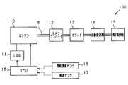
- FIG. 1 is a diagram illustrating an overall configuration of a vehicle according to the present embodiment.
- FIG. 2 is a control flowchart executed by the ECU according to this embodiment.
- FIG. 3 is a control flowchart executed by an ECU according to another embodiment.
- FIG. 1 shows a configuration of a vehicle 100 including an internal combustion engine (hereinafter referred to as an engine).
- an output shaft (crankshaft) 6 of the engine 10 has an integrated starter generator (ISG) 11 having an engine start function and an output auxiliary function in addition to a power generation function driven by the crankshaft 6 to generate power.
- ISG integrated starter generator
- the ISG 11 applies torque from the outside of the engine 10 to the crankshaft 6 from the outside of the engine 10 at the time of start-up after warm-up and when the combustion of the engine 10 is stopped, such as when restarting after idling stop. 10 is started.
- the ISG 11 assists driving of the crankshaft 6 by applying torque to the crankshaft 6 from the outside while the vehicle is running after the engine 10 is started. Therefore, ISG11 corresponds to an electric motor.
- crankshaft 6 a fluid friction connecting portion (torque converter) 12, a clutch (corresponding to a clutch device) 13, an automatic transmission (corresponding to an automatic transmission) 14, and a drive wheel 15 are connected.
- the crankshaft 6 can be connected to the drive wheels 15 of the vehicle via the torque converter 12, the clutch 13, and the automatic transmission 14.
- the automatic transmission 14 is configured by, for example, a well-known multi-stage transmission mechanism including a planetary gear mechanism, CVT, or the like.
- the clutch 13 is referred to as a forward clutch or a forward clutch.
- the clutch 13 is a forward range (drive (D)) other than the parking (P) range, reverse (R) range, and neutral (N) range of the automatic transmission 14. Range, 1st speed range, 2nd speed range, etc.) are selected.
- the clutch 13 When the clutch 13 is connected, the torque of the engine 10 is transmitted to the drive wheels 15 via the crankshaft 6.
- the electronic control unit (ECU) 16 includes a microcomputer, and controls the output of the engine 10 and the output of the ISG 11 based on various information taken from the outside.
- the various information corresponds to a vehicle speed (vehicle speed) detected by a vehicle speed sensor (corresponding to a vehicle speed detection unit) 17, a rotational speed of the engine 10 detected by the rotational speed sensor 18, and the like.
- the ECU 16 corresponds to an execution condition determining unit, an inertia traveling unit, a restart condition determining unit, a pushing unit, a starting unit, a double starting unit, a forced starting unit, and a shift control unit.
- the ECU 16 executes restart control of the engine 10 shown in FIG.
- the restart control of the engine 10 shown in FIG. 2 is repeatedly executed by the ECU 16 at a predetermined cycle while the ECU 16 is powered on.
- the execution permission conditions include, for example, environmental conditions, vehicle conditions, power supply conditions, engine conditions, and driver operation conditions. More details
- the environmental conditions include that the outside air temperature is in a predetermined range and the atmospheric pressure is in a predetermined range.
- the vehicle conditions are that the vehicle speed ve is within a predetermined range (for example, 40 to 120 km / h), the road surface gradient (inclination) is within the predetermined range, the driving amount of the electric load is less than the predetermined value, and the brake negative pressure is This includes a case where the pressure is larger than the predetermined negative pressure and no prohibition request is issued from another ECU or the like.
- the power supply conditions include that the battery capacity is within a predetermined range, not generating power (except when a power generation request is generated during coasting), and no prohibition request from the power system.
- the temperature of engine coolant is within a predetermined range
- the temperature of transmission hydraulic oil is within a predetermined range.
- the driver operating conditions are accelerator off, brake off, and shift lever position in the D range.
- step 110 the vehicle is caused to perform idling stop coasting.
- the idling stop coasting refers to a state in which the vehicle is coasted by stopping fuel supply to the engine 10 and disengaging the clutch 13.
- step 120 it is determined whether or not a restart request for the engine 10 has been made. In the present embodiment, for example, it is determined that a restart request has occurred when the accelerator operation amount Acc as the operation amount by which the accelerator pedal is depressed is larger than the predetermined operation amount Acc0. If it is not determined that a restart request for the engine 10 has occurred (S120: NO), the determination in step 120 is repeated until a restart request for the engine 10 occurs. If it is determined that a restart request for the engine 10 has occurred (S120: YES), the process proceeds to step 130.
- step 130 the ISG 11 is driven, and the engine 10 is rotated by the torque generated thereby, and the engine 10 is tried to start by burning the fuel. At this time, the vehicle disengages the clutch 13 and maintains the inertial running state.
- step 140 it is determined whether or not the engine 10 has been successfully started.
- the rotational speed of the engine 10 detected by the rotational speed sensor 18 exceeds the threshold value ⁇
- the threshold value ⁇ is set as an engine speed that is considered to increase at a minimum when the engine 10 is successfully started. If it is determined that the engine 10 has been successfully started (S140: YES), the clutch 13 is engaged and this control is terminated. If it is not determined that the engine 10 has been successfully started (S140: NO), the process proceeds to step 150.
- step 150 the vehicle speed sensor 17 is used to detect the vehicle speed ve.
- step 160 it is determined whether the vehicle speed ve detected by the vehicle speed sensor 17 is higher than a predetermined speed ve0 (for example, 20 km / h).
- the predetermined speed ve0 is set as a vehicle speed at which the engine 10 can be restarted by pushing.
- the process proceeds to step 170.
- step 170 the clutch 13 is engaged and the engine 10 is restarted by pushing. Specifically, when the clutch 13 is engaged, the rotation of the drive wheel 15 due to inertial traveling is transmitted to the crankshaft 6 via the automatic transmission 14, the clutch 13, and the torque converter 12 to rotate the engine 10. . Accordingly, the engine 10 is started by burning the fuel while the engine 10 is rotated. And this control is complete
- Step 180 since the vehicle speed ve is low, the rotation speed of the engine 10 cannot be sufficiently increased only by the rotation transmitted from the drive wheel 15, and the output of the ISG 11 is added in addition to the rotation transmitted from the drive wheel 15. The rotational speed of the engine 10 is increased. In this state, the process proceeds to step 170, and the engine 10 is restarted by pushing. And this control is complete
- the ECU 16 according to the present embodiment has the following effects.
- the ISG 11 when there is a restart request for the engine 10, the ISG 11 first tries to restart the engine 10. If the engine 10 can be restarted at this time, a shock or the like due to a deceleration change that occurs when the pressing is performed does not occur, and the driver can drive without feeling uncomfortable.
- the engine 10 is started by pushing without driving assistance by the ISG 11. As a result, it is possible to attempt to start the engine 10 only with the driving force generated by inertial running.
- the ISG 11 tries to restart the engine 10 by pushing while assisting the driving of the engine 10.
- the vehicle speed ve is lower than the predetermined speed ve0, if the engine 10 is started by pushing only with the driving force generated by inertial running, the rotation speed of the engine 10 cannot be sufficiently increased and the start is started. There is a risk of failure.
- the engine 10 can be driven by the ISG 11 to assist the restart of the engine 10 more reliably. Further, by assisting the drive of the engine 10 by the ISG 11, it is possible to mitigate a shock caused by a deceleration change that occurs when the pushing is performed, and thus it is possible to suppress deterioration in drivability.
- the clutch 13 is disconnected in order to perform idling stop coasting.
- the predetermined speed ve0 was set as a vehicle speed at which the engine 10 can be restarted by pushing.
- the predetermined speed ve0 is not limited to the above setting, and may be set as a vehicle speed that can be increased to a predetermined rotational speed as a rotational speed necessary for starting the engine 10, for example. Further, the predetermined speed ve0 may be changed by changing the gear ratio of the automatic transmission 14.
- the engine 10 when the engine 10 is requested to be restarted, the engine 10 is first tried to be restarted by the ISG 11, and when the engine 10 is not restarted, the engine 10 is restarted by pushing.
- the engine 10 may be restarted by pushing, and if the engine 10 is not restarted, the engine 10 may be restarted by the ISG 11. If the engine 10 can be restarted at this time by trying to restart the engine 10 by pushing first, it is not necessary to use the ISG 11. Therefore, compared with the case where the engine 10 is first restarted by the ISG 11, the power consumption can be suppressed, and the fuel consumption can be saved.
- step 130 of FIG. 2 if restart of the engine 10 by the ISG 11 fails, the process proceeds to the next step. About this, you may try restarting the engine 10 by ISG11 in multiple times. Similarly, in step 170, the engine 10 may be restarted a plurality of times by pushing.
- step 150, step 160, and step 180 may be deleted.
- the automatic transmission 14 is set so that the rotational speed of the engine 10 becomes higher than a predetermined rotational speed (a rotational speed necessary for starting the engine 10) according to the vehicle speed ve. If the current gear ratio is changed, the rotational speed of the engine 10 can be more reliably increased.
- the rotational speed of the engine 10 if the rotational speed of the engine 10 cannot be made higher than the predetermined rotational speed even if the gear ratio of the automatic transmission 14 is increased, the rotational speed of the engine 10 is output by the output of the ISG 11. To assist. Thereby, compared with the control of FIG. 2, the output of ISG11 can be suppressed and it becomes possible to suppress power consumption.
- FIG. 3 is a modification of part of the procedure in FIG. That is, between step 210 corresponding to step 110 and step 320 corresponding to step 120, step 250 corresponding to step 150 and step 260 corresponding to step 160 move. If step 260 is NO, steps 270 to 290 are inserted in place of step 180.
- step 260 the control in the case where it is not determined in step 260 that the vehicle speed ve detected by the vehicle speed sensor 17 is higher than the predetermined speed ve0 (S260: NO) will be described.
- step 270 since the vehicle speed ve is not higher than the predetermined speed ve0, the restart of the engine 10 cannot be attempted twice, and the engine 10 is forcibly started.
- step 280 the ISG 11 is driven, and the engine 10 is started by burning the fuel while the crankshaft 6 is rotated with the torque generated thereby.
- step 290 by maintaining the state where the clutch 13 is disengaged, coasting (idle coasting) is continued in a state where the engine 10 is driven (idle state). And this control is complete
- steps 200, 210, 250, 260, 320, 330, 340, and 370 in FIG. 3 are respectively performed in steps 100, 110, 120, 130, 140, 150, The same processing as 160 and 170 is performed.
- the engine 10 is started, so that the problem about the restart of the engine 10 is solved, and the inertial running state of the vehicle is kept as it is with the engine 10 started. Can be maintained.
Landscapes
- Engineering & Computer Science (AREA)
- Chemical & Material Sciences (AREA)
- Combustion & Propulsion (AREA)
- Mechanical Engineering (AREA)
- Transportation (AREA)
- General Engineering & Computer Science (AREA)
- Automation & Control Theory (AREA)
- Control Of Vehicle Engines Or Engines For Specific Uses (AREA)
- Hybrid Electric Vehicles (AREA)
- Control Of Driving Devices And Active Controlling Of Vehicle (AREA)
Abstract
内燃機関(10)と、内燃機関の出力軸(6)に接続され、出力軸にトルクを付与することで内燃機関の回転速度を上昇させる電動機(11)と、駆動輪(15)と、内燃機関の出力軸と駆動輪との動力伝達を断接するクラッチ装置(13)と、を備える車両に適用される再始動制御装置(16)であって、車両が惰性走行中に、内燃機関の再始動を行う再始動条件が成立したことを判定する再始動条件判定部と、押しがけにて始動を行う押しがけ部と、電動機を使用して始動を行う始動部と、再始動条件が成立したことが判定された場合に、押しがけ部及び始動部の一方により内燃機関を始動させ、内燃機関が始動されなかった場合に他方により内燃機関を始動させる二重始動部と、を備えることを特徴とする再始動制御装置。
Description
本出願は、2015年5月12日に出願された日本特許出願番号2015-97589号に基づくもので、ここにその記載内容を援用する。
本開示は、内燃機関の再始動を制御する制御装置に関する。
燃費向上のために、内燃機関(以下、エンジンと呼称)を停止して惰性走行を行うアイドリングストップコースティング技術が近年求められてきている。
特許文献1では、惰性走行時にエンジンの再始動要求があり、車両の駆動輪と接続されている出力軸の回転変化量が設定値よりも高かった場合には、エンジンの出力軸にクラッチを結合させることで、走行中の車両が保有する駆動力により内燃機関の回転速度を上昇させ、エンジンを再始動させている(以下、押しがけと呼称)。また、出力軸の回転変化量が設定値よりも低かった場合には、スタータモータにてエンジンを始動させている。
このようなアイドリングストップコースティング技術が搭載された車両では、高速走行中にエンジンを停止させる状態が生じてしまうため、エンジンの再始動は確実に実施されることが求められる。しかし、特許文献1に記載されるような「押しがけ」によるエンジンの再始動は必ずしも確実なものといえず、また同様にスタータモータによるエンジンの再始動も必ずしも確実なものとはいえない。
本開示は、惰性走行中にエンジンの再始動を行う際、エンジンの再始動をより確実に実施させる始動制御装置を提供することを目的とする。
本開示は、内燃機関と、前記内燃機関の出力軸に接続され、前記出力軸にトルクを付与することで前記内燃機関の回転速度を上昇させる電動機と、駆動輪と、前記内燃機関の出力軸と前記駆動輪との動力伝達を断接するクラッチ装置と、を備える車両に適用される再始動制御装置である。
この再始動制御装置は、前記車両が惰性走行を実施する実施条件の成立を判定する実施条件判定部と、前記実施条件判定部により前記実施条件の成立が判定された場合に、前記内燃機関への燃料供給を停止するとともに前記クラッチ装置を遮断状態にして前記車両を惰性走行させる惰性走行部と、前記惰性走行中に、前記内燃機関の再始動を行う再始動条件が成立したことを判定する再始動条件判定部と、前記クラッチ装置を接続状態にして、前記惰性走行により発生している駆動力で前記内燃機関の回転速度を上昇させたのちに、前記内燃機関への燃料供給を再開させて始動を行う押しがけ部と、前記電動機により前記内燃機関の回転速度を上昇させたのちに、前記内燃機関への燃料供給を再開させて始動を行う始動部と、前記再始動条件判定部により前記再始動条件が成立したことが判定された場合に、前記押しがけ部及び前記始動部の一方により前記内燃機関を始動させ、前記内燃機関が始動されなかった場合に他方により前記内燃機関を始動させる二重始動部と、を備えることを特徴とする。
この再始動制御装置は、前記車両が惰性走行を実施する実施条件の成立を判定する実施条件判定部と、前記実施条件判定部により前記実施条件の成立が判定された場合に、前記内燃機関への燃料供給を停止するとともに前記クラッチ装置を遮断状態にして前記車両を惰性走行させる惰性走行部と、前記惰性走行中に、前記内燃機関の再始動を行う再始動条件が成立したことを判定する再始動条件判定部と、前記クラッチ装置を接続状態にして、前記惰性走行により発生している駆動力で前記内燃機関の回転速度を上昇させたのちに、前記内燃機関への燃料供給を再開させて始動を行う押しがけ部と、前記電動機により前記内燃機関の回転速度を上昇させたのちに、前記内燃機関への燃料供給を再開させて始動を行う始動部と、前記再始動条件判定部により前記再始動条件が成立したことが判定された場合に、前記押しがけ部及び前記始動部の一方により前記内燃機関を始動させ、前記内燃機関が始動されなかった場合に他方により前記内燃機関を始動させる二重始動部と、を備えることを特徴とする。
上記構成によれば、内燃機関と、駆動輪と、内燃機関の出力軸と駆動輪との動力伝達を断接するクラッチ装置と、内燃機関の出力軸にトルクを付与することで内燃機関の回転速度を上昇させる電動機とを有した車両に適用される再始動制御装置である。この再始動制御装置には、実施条件判定部が備わっており、この実施条件判定部により車両が惰性走行を実施する実施条件が成立したかが判定される。実施条件が成立したと判定された場合には、惰性走行部により内燃機関への燃料供給を停止するとともにクラッチ装置を遮断状態にして車両を惰性走行状態とさせる。そして、車両が惰性走行中に、再始動条件判定部により内燃機関の再始動を行う再始動条件が成立したかが判定される。
本再始動制御装置は、惰性走行時に内燃機関の再始動を実施する際、二つの構成で再始動を試みる。一つは、クラッチ装置を接続して、惰性走行により発生している駆動力で内燃機関の回転速度を上昇させたのちに、内燃機関への燃料供給を再開させて始動を行う押しがけ部である。もう一つは、電動機により内燃機関の回転速度を上昇させたのちに、内燃機関への燃料供給を再開させて始動を行う始動部である。このような構成において、再始動条件判定部により再始動条件が成立したことが判定された場合に、二重始動部は押しがけ部及び始動部の一方により内燃機関を始動させ、内燃機関が始動されなかった場合に他方により内燃機関を始動させる。このように、内燃機関の再始動を二重に試みることで、内燃機関の再始動をより確実に実施することが可能となる。
本開示についての上記目的およびその他の目的、特徴や利点は、添付の図面を参照しながら下記の詳細な記述により、より明確になる。その図面は、
図1は、本実施形態にかかる車両の全体構成を示す図であり、
図2は、本実施形態にかかるECUにより実行される制御フローチャートであり、
図3は、他の実施形態にかかるECUにより実行される制御フローチャートである。
以下、本開示にかかる内燃機関の始動制御装置を、図面を参照しつつ説明する。
図1に、内燃機関(以下、エンジンと呼称)を含む車両100の構成を示す。図示されるように、エンジン10の出力軸(クランク軸)6には、クランク軸6によって駆動されて発電を行う発電機能に加えてエンジン始動機能及び出力補助機能を有するISG(Integrated Starter Generator)11が接続されている。ISG11は、エンジン始動機能として、アイドリングストップ後の再始動時等、暖機後であってエンジン10の燃焼が停止されている始動時に、クランク軸6に対してエンジン10外部よりトルクを与えてエンジン10を始動させる。また、ISG11は、出力補助機能として、エンジン10の始動後において車両の走行中にクランク軸6に対して外部よりトルクを与えてクランク軸6の駆動を補助する。よって、ISG11は電動機に該当する。
また、クランク軸6から順に、流体摩擦接続部(トルクコンバータ)12、クラッチ(クラッチ装置に該当)13、自動変速機(自動変速装置に該当)14、駆動輪15へ接続されている。そして、これらトルクコンバータ12とクラッチ13と自動変速機14とを介して、クランク軸6は車両の駆動輪15に接続可能とされている。
ここで、自動変速機14は、例えば遊星歯車機構を備える周知の多段式変速機構、CVT等で構成されている。クラッチ13は、前進クラッチやフォワードクラッチと呼ばれるものであり、通常走行において、自動変速機14のパーキング(P)レンジ、後進(R)レンジ、ニュートラル(N)レンジ以外の前進レンジ(ドライブ(D)レンジ、1速レンジ、2速レンジ等)が選択された状態で接続される。そして、クラッチ13が接続された状態では、エンジン10のトルクがクランク軸6を介して駆動輪15に伝達される状態となる。
電子制御装置(ECU)16は、マイクロコンピュータを備えて構成されており、外部から取り込まれる各種情報に基づき、エンジン10の出力を制御したり、ISG11の出力を制御したりする。なお、各種情報とは、車速センサ(車速検出部に該当)17により検出された車両の速度(車速)や回転速度センサ18により検出されたエンジン10の回転速度などが該当する。
本実施形態において、ECU16は実施条件判定部、惰性走行部、再始動条件判定部、押しがけ部、始動部、二重始動部、強制始動部、及び変速制御部に該当する。
このような構成を備える車両100において、高速走行中にエンジン10を停止させ惰性走行状態に移った場合(アイドリングストップコースティング)を想定する。この場合、エンジン10の再始動は確実に実施されることが求められる。しかし、従来の技術を実施した場合(例えばスタータによる再始動)に、エンジン10の再始動を失敗する可能性がある。
この対策として、本実施形態では、ECU16により後述する図2のエンジン10の再始動制御を実行する。これにより、エンジン10の再始動要求が発生した際には、車両が既に保有している運動エネルギに基づくトルクを用いてのエンジン10の再始動(押しがけ)と、ISG11により出力されるトルクを用いてのエンジン10の再始動とで、二重にエンジン10の再始動を試みることが出来る。
以下、ECU16が実行する図2のエンジン10の再始動制御の制御内容を説明する。図2に示すエンジン10の再始動制御は、ECU16が電源オンしている期間中にECU16によって所定周期で繰り返し実行される。
本制御が起動されると、まずステップ100にて、アイドリングストップコースティングを行う上での実施許可条件を満たしたか否かが判定される。実施許可条件とは、例えば環境条件、車両条件、電源条件、エンジン条件、ドライバ操作条件よりなる。より詳しくは、
環境条件には、外気温が所定範囲であり、かつ大気圧が所定範囲であることが含まれる。
車両条件には、車速veが所定範囲(例えば40~120km/h)内であり、路面勾配(傾斜)が所定範囲内であり、電気負荷の駆動量が所定値以下であり、ブレーキ負圧が所定負圧よりも大きく、かつ他のECU等からの禁止要求がないことが含まれる。
電源条件には、バッテリ容量が所定範囲内であり、発電中でない(惰性走行中に発電要求が生じる場合を除く)、かつ電源システムからの禁止要求がないことが含まれる。
エンジン条件には、エンジン冷却水の温度が所定範囲内であり、トランスミッション作動油の温度が所定範囲内である。
ドライバ操作条件には、アクセルオフであり、ブレーキオフであり、シフトレバー位置がDレンジである。
環境条件には、外気温が所定範囲であり、かつ大気圧が所定範囲であることが含まれる。
車両条件には、車速veが所定範囲(例えば40~120km/h)内であり、路面勾配(傾斜)が所定範囲内であり、電気負荷の駆動量が所定値以下であり、ブレーキ負圧が所定負圧よりも大きく、かつ他のECU等からの禁止要求がないことが含まれる。
電源条件には、バッテリ容量が所定範囲内であり、発電中でない(惰性走行中に発電要求が生じる場合を除く)、かつ電源システムからの禁止要求がないことが含まれる。
エンジン条件には、エンジン冷却水の温度が所定範囲内であり、トランスミッション作動油の温度が所定範囲内である。
ドライバ操作条件には、アクセルオフであり、ブレーキオフであり、シフトレバー位置がDレンジである。
上記の実施許可条件が満たされたと判定しなかった場合には(S100:NO)、アイドリングストップコースティングの実施を許可しないとして、本制御を終了する。上記の実施許可条件が満たされたと判定した場合には(S100:YES)、ステップ110に進み、車両にアイドリングストップコースティングを実施させる。なお、アイドリングストップコースティングとは、エンジン10への燃料供給を停止するとともに、クラッチ13を遮断することで、車両を惰性走行させる状態を指す。
ステップ120では、エンジン10の再始動要求があったか否かを判定する。本実施形態では、例えば、アクセルペダルが踏み込まれた操作量としてのアクセル操作量Accが所定操作量Acc0よりも大きい場合に、再始動要求が発生したと判定する。エンジン10の再始動要求が発生したと判定されなかった場合には(S120:NO)、エンジン10の再始動要求が発生するまでステップ120の判定を繰り返す。エンジン10の再始動要求が発生したと判定された場合には(S120:YES)、ステップ130に進む。
ステップ130では、ISG11を駆動させ、それにより生じたトルクでエンジン10を回転させた状態で、燃料の燃焼を実施させることでエンジン10の始動を試みる。なお、このとき、車両はクラッチ13を遮断しており、惰性走行状態を維持している。
ステップ140では、エンジン10の始動に成功したか否かを判定する。本実施形態では、例えば回転速度センサ18により検出されたエンジン10の回転速度が閾値αを超えて高くなった場合にエンジン10の始動に成功したことを判定する。なお閾値αとは、エンジン10の始動に成功した際に最低限上昇すると考えられるエンジン回転速度として設定される。エンジン10の始動に成功したと判定された場合には(S140:YES)、クラッチ13を係合して本制御を終了する。エンジン10の始動に成功していると判定されなかった場合には(S140:NO)、ステップ150に進む。
ステップ150では、車速センサ17により車速veを検出させる。そしてステップ160にて車速センサ17より検出させた車速veが所定速度ve0(例えば20km/h)よりも高いか否かが判定される。所定速度ve0とは、押しがけによるエンジン10の再始動を実施させることが可能な車速として設定される。車速veが所定速度ve0よりも高いと判定された場合には(S160:YES)、ステップ170に進む。
ステップ170では、クラッチ13を係合させ、押しがけによるエンジン10の再始動を実施させる。具体的には、クラッチ13を係合させることで惰性走行による駆動輪15の回転が、自動変速機14、クラッチ13、及びトルクコンバータ12を介してクランク軸6に伝達され、エンジン10を回転させる。これにより、エンジン10を回転させた状態で燃料の燃焼を実施させることでエンジン10の始動を実施させる。そして、本制御を終了する。
車速veが所定速度ve0よりも高いと判定されなかった場合には(S160:NO)、ステップ180に進む。ステップ180では、車速veが低いために駆動輪15から伝達される回転だけではエンジン10の回転速度を十分に上昇させることができないとして、駆動輪15から伝達される回転に加えてISG11の出力によりエンジン10の回転速度を上昇させる。その状態で、ステップ170に進み、押しがけによるエンジン10の再始動を実施させる。そして、本制御を終了する。
上記構成により、本実施形態に係るECU16は、以下の効果を奏する。
惰性走行時にエンジン10の再始動を実施する際、二つの構成で再始動を試みる。一つは、ISG11によりエンジン10の回転速度を上昇させたのちに、エンジン10への燃料供給を再開させて始動を行うものである。もう一つは、クラッチ13を接続して、惰性走行により発生している駆動力でエンジン10の回転速度を上昇させたのちに、エンジン10への燃料供給を再開させて始動を行うものである(押しがけ)。このような構成において、エンジン10の再始動要求があったことが判定された場合に、まずISG11によりエンジン10の再始動を試み、エンジン10が再始動されなかった場合に押しがけによりエンジン10を再始動させる。このように、エンジン10の再始動を二重に試みることで、エンジン10の再始動をより確実に実施することが可能となる。
本実施形態では、エンジン10の再始動要求があった場合に、まずISG11によりエンジン10の再始動を試みる。このときにエンジン10を再始動させることができれば、押しかけを実施する際に生じる減速変化によるショックなどが生じず、ドライバは違和感を覚えることなく運転することが可能となる。
車速センサ17により検出された車速veが所定速度ve0よりも高い場合には、ISG11による駆動補助なしに押しがけによるエンジン10の始動を試みる。これにより、惰性走行により発生している駆動力のみでエンジン10の始動を試みることが可能となる。車速センサ17により検出された車速veが所定速度ve0よりも低い場合には、ISG11によりエンジン10の駆動を補助しながら押しがけによるエンジン10の再始動を試みる。車速veが所定速度ve0よりも低い場合に、惰性走行により発生している駆動力のみで押しがけによるエンジン10の始動を試みると、エンジン10の回転速度を十分に上昇させることができず始動を失敗するおそれがある。よって、車速veが所定速度ve0よりも低い場合にはISG11によりエンジン10の駆動を補助させることで、押しがけによるエンジン10の再始動をより確実に実施することが可能となる。また、ISG11によりエンジン10の駆動を補助させることで、押しかけを実施する際に生じる減速変化によるショックなどを緩和することができるため、ドライバビリティの悪化を抑制する事が可能となる。
なお、上記実施形態を、以下のように変更して実施することもできる。
上記実施形態では、アイドリングストップコースティングを実施するために、クラッチ13を遮断していた。このことについて、例えばトルクコンバータ12内にあるロックアップクラッチを遮断することでアイドリングストップコースティングを実施してもよい。
所定速度ve0とは、押しがけによるエンジン10の再始動を実施させることが可能な車速として設定されていた。このことについて、所定速度ve0は上記設定に限らず、例えばエンジン10を始動させるのに必要な回転速度としての所定回転速度まで上昇させることが可能な車速として設定してもよい。また、自動変速機14の変速比を変更することにより、この所定速度ve0を変更してもよい。
上記実施形態では、エンジン10の再始動要求があった場合に、まずISG11によりエンジン10の再始動を試み、エンジン10が再始動されなかった場合に押しがけによりエンジン10を再始動させていた。このことについて、まず押しがけによりエンジン10を再始動させ、エンジン10が再始動されなかった場合には、ISG11によりエンジン10の再始動を試みてもよい。最初に押しがけによるエンジン10の再始動を試みることで、このときにエンジン10を再始動させることができれば、ISG11を使用しないですむ。よって、最初にISG11によりエンジン10の再始動を試みる場合と比較して消費電力を抑えることができ、ひいては燃料消費量を節約することが可能となる。
図2のステップ130において、ISG11によるエンジン10の再始動に失敗すると次のステップに進んでいた。このことについて、ISG11によるエンジン10の再始動を複数回試みてもよい。また、ステップ170も同様に、押しがけによるエンジン10の再始動を複数回試みてもよい。
図2の手順について、ステップ150、ステップ160、及びステップ180は削除してもよい。この場合、車速veが低いと、押しがけによりエンジン10を再始動させようとしてもエンジン10の回転速度を十分に上昇させることができず、エンジン10の再始動を失敗するおそれがある。よって、本別例を実施する際には、車速veに応じて、エンジン10の回転速度が所定回転速度(エンジン10を始動させるのに必要な回転速度)よりも高くなるように自動変速機14の現在の変速比を変更させると、より確実にエンジン10の回転速度を上昇させることが可能となる。
本別例について、もし自動変速機14の変速比を大きくしても、エンジン10の回転速度を所定回転速度よりも高くすることが出来なかった場合には、ISG11の出力によりエンジン10の回転速度を補助する。これにより、図2に記載の制御と比較して、ISG11の出力を抑えることができ、電力消費量を抑えることが可能となる。
図3は、図2の手順の一部を変容したものである。すなわちステップ110に該当するステップ210とステップ120に該当するステップ320との間に、ステップ150に該当するステップ250及びステップ160に該当するステップ260が移動する。そして、ステップ260がNOであった場合に、ステップ180に代わってステップ270~ステップ290が挿入される。
以下にステップ260にて、車速センサ17より検出させた車速veが所定速度ve0よりも高いと判定されなかった場合(S260:NO)の制御を説明する。
車速veが所定速度ve0より高いと判定されなかった場合には(S260:NO)、ステップ270に進む。ステップ270では、車速veが所定速度ve0よりも高くないために、エンジン10の再始動を二重に試みることができないとして、エンジン10の強制始動を実施させる。
ステップ280では、ISG11を駆動させ、それにより生じたトルクでクランク軸6を回転させた状態で、燃料の燃焼を実施させることでエンジン10の始動を実施させる。そしてステップ290において、クラッチ13を遮断した状態を維持することで、エンジン10を駆動させた状態(アイドル状態)で惰性走行(アイドルコースティング)を続行させる。そして、本制御を終了する。
それ以外のステップについて、図3の各ステップ200,210,250,260,320,330,340,及び370の処理は、それぞれ、図2の各ステップ100,110,120,130,140,150,160,及び170の処理と同一である。
これにより、車速veが所定速度ve0よりも低くなってもエンジン10を始動させることで、エンジン10の再始動についての問題を解消し、且つエンジン10を始動した状態で車両の惰性走行状態をそのまま維持することが可能となる。
本開示は、実施例に準拠して記述されたが、本開示は当該実施例や構造に限定されるものではないと理解される。本開示は、様々な変形例や均等範囲内の変形をも包含する。加えて、様々な組み合わせや形態、さらには、それらに一要素のみ、それ以上、あるいはそれ以下、を含む他の組み合わせや形態をも、本開示の範疇や思想範囲に入るものである。
Claims (6)
- 内燃機関(10)と、
前記内燃機関の出力軸(6)に接続され、前記出力軸にトルクを付与することで前記内燃機関の回転速度を上昇させる電動機(11)と、
駆動輪(15)と、
前記内燃機関の出力軸と前記駆動輪との動力伝達を断接するクラッチ装置(13)と、を備える車両(100)に適用される再始動制御装置(16)であって、
前記車両が惰性走行を実施する実施条件の成立を判定する実施条件判定部と、
前記実施条件判定部により前記実施条件の成立が判定された場合に、前記内燃機関への燃料供給を停止するとともに前記クラッチ装置を遮断状態にして前記車両を惰性走行させる惰性走行部と、
前記惰性走行中に、前記内燃機関の再始動を行う再始動条件が成立したことを判定する再始動条件判定部と、
前記クラッチ装置を接続状態にして、前記惰性走行により発生している駆動力で前記内燃機関の回転速度を上昇させたのちに、前記内燃機関への燃料供給を再開させて始動を行う押しがけ部と、
前記電動機により前記内燃機関の回転速度を上昇させたのちに、前記内燃機関への燃料供給を再開させて始動を行う始動部と、
前記再始動条件判定部により前記再始動条件が成立したことが判定された場合に、前記押しがけ部及び前記始動部の一方により前記内燃機関を始動させ、前記内燃機関が始動されなかった場合に他方により前記内燃機関を始動させる二重始動部と、
を備えることを特徴とする再始動制御装置。 - 前記車両は前記車両の速度である車速を検出する車速検出部(17)を備え、
前記押しがけ部は、前記車速検出部により検出された車速が所定速度よりも高い場合には、前記電動機による駆動補助なしに前記内燃機関の始動を試み、一方で、前記車速検出部により検出された車速が所定速度よりも低い場合には、前記電動機により前記内燃機関の駆動を補助しながら始動を試みることを特徴とする請求項1に記載の再始動制御装置。 - 前記車両は、
前記車両の速度である車速を検出する車速検出部(17)と、
前記内燃機関の出力軸の回転速度と前記駆動輪の回転速度との変速比を変更する自動変速装置(14)と、
を備え、
前記再始動制御装置は、前記自動変速装置の変速比を制御する変速制御部を備え、
前記押しがけ部は、前記車速検出部により検出された前記車速に応じて、前記内燃機関の回転速度が所定回転速度を超えて高くなるように前記変速制御部により変速比を変更させた状態で再始動を行うことを特徴とする請求項1又は2に記載の再始動制御装置。 - 前記車両が前記惰性走行中に車速が前記押しがけ部を実行可能とする閾値よりも低くなると強制的に前記始動部により内燃機関を再始動する強制始動部を備えることを特徴とする請求項1乃至3のいずれか1項に記載の再始動制御装置。
- 前記二重始動部は、まず前記始動部により前記内燃機関を始動させ、前記内燃機関が始動されなかった場合に、前記押しがけ部により前記内燃機関を始動させることを特徴とする請求項1乃至4のいずれか1項に記載の再始動制御装置。
- 前記二重始動部は、まず前記押しがけ部により前記内燃機関を始動させ、前記内燃機関が始動されなかった場合に、前記始動部により前記内燃機関を始動させることを特徴とする請求項1乃至4のいずれか1項に記載の再始動制御装置。
Priority Applications (3)
| Application Number | Priority Date | Filing Date | Title |
|---|---|---|---|
| DE112016002143.7T DE112016002143B4 (de) | 2015-05-12 | 2016-04-28 | Neustartsteuerungsvorrichtung für eine verbrennungskraftmaschine |
| US15/558,379 US10479359B2 (en) | 2015-05-12 | 2016-04-28 | Restart control device for internal combustion engine |
| CN201680027061.4A CN107532527B (zh) | 2015-05-12 | 2016-04-28 | 内燃机的再启动控制装置 |
Applications Claiming Priority (2)
| Application Number | Priority Date | Filing Date | Title |
|---|---|---|---|
| JP2015-097589 | 2015-05-12 | ||
| JP2015097589A JP6295998B2 (ja) | 2015-05-12 | 2015-05-12 | 内燃機関の再始動制御装置 |
Publications (1)
| Publication Number | Publication Date |
|---|---|
| WO2016181634A1 true WO2016181634A1 (ja) | 2016-11-17 |
Family
ID=57248220
Family Applications (1)
| Application Number | Title | Priority Date | Filing Date |
|---|---|---|---|
| PCT/JP2016/002231 Ceased WO2016181634A1 (ja) | 2015-05-12 | 2016-04-28 | 内燃機関の再始動制御装置 |
Country Status (5)
| Country | Link |
|---|---|
| US (1) | US10479359B2 (ja) |
| JP (1) | JP6295998B2 (ja) |
| CN (1) | CN107532527B (ja) |
| DE (1) | DE112016002143B4 (ja) |
| WO (1) | WO2016181634A1 (ja) |
Cited By (3)
| Publication number | Priority date | Publication date | Assignee | Title |
|---|---|---|---|---|
| GB2559742A (en) * | 2017-02-15 | 2018-08-22 | Gm Global Tech Operations Llc | A method of cranking an internal combustion engine of a motor vehicle |
| FR3088602A1 (fr) | 2018-11-16 | 2020-05-22 | Psa Automobiles Sa | Procede de redemarrage autonome d’un moteur thermique de vehicule automobile |
| US12473364B2 (en) | 2018-11-14 | 2025-11-18 | Regeneron Pharmaceuticals, Inc. | Intralesional administration of PD-1 inhibitors for treating skin cancer |
Families Citing this family (16)
| Publication number | Priority date | Publication date | Assignee | Title |
|---|---|---|---|---|
| US10451022B2 (en) | 2016-11-02 | 2019-10-22 | Paccar Inc | Intermittent restart for automatic engine stop start system |
| JP6799486B2 (ja) * | 2017-03-17 | 2020-12-16 | 株式会社Subaru | アイドリングストップ制御装置 |
| US10487762B2 (en) * | 2017-09-26 | 2019-11-26 | Paccar Inc | Systems and methods for predictive and automatic engine stop-start control |
| US10690103B2 (en) | 2017-09-26 | 2020-06-23 | Paccar Inc | Systems and methods for using an electric motor in predictive and automatic engine stop-start systems |
| JP6852696B2 (ja) * | 2018-02-26 | 2021-03-31 | トヨタ自動車株式会社 | 車両のエンジン始動制御装置 |
| US10883566B2 (en) | 2018-05-09 | 2021-01-05 | Paccar Inc | Systems and methods for reducing noise, vibration and/or harshness associated with cylinder deactivation in internal combustion engines |
| US10746255B2 (en) | 2018-05-09 | 2020-08-18 | Paccar Inc | Systems and methods for reducing noise, vibration, and/or harshness during engine shutdown and restart |
| JP7163837B2 (ja) * | 2019-03-20 | 2022-11-01 | トヨタ自動車株式会社 | ハイブリッド車両の制御装置 |
| CN110758372B (zh) * | 2019-09-25 | 2021-04-16 | 潍柴动力股份有限公司 | 双行星排混合动力系统的控制方法、控制装置及车辆 |
| SE543691C2 (en) * | 2019-10-02 | 2021-06-08 | Scania Cv Ab | Control device and method for starting a combustion engine during free-wheeling, a vehicle with such device, computer program for executing the method and computer readable medium containing the program |
| JP7492325B2 (ja) * | 2019-11-05 | 2024-05-29 | 株式会社Subaru | エンジンシステム |
| JP7211536B2 (ja) * | 2019-12-06 | 2023-01-24 | 日産自動車株式会社 | ハイブリッド車両制御方法及びハイブリッド車両制御装置 |
| US12246717B2 (en) * | 2021-09-10 | 2025-03-11 | Cummins Inc. | Systems and methods for re-starting engine during coasting event |
| JP7632388B2 (ja) * | 2022-05-25 | 2025-02-19 | トヨタ自動車株式会社 | ハイブリッド車両の制御装置 |
| EP4560132A1 (en) * | 2023-11-22 | 2025-05-28 | Volvo Truck Corporation | Predictive engine stop-start based on clutch energy |
| EP4635810A1 (en) * | 2024-04-15 | 2025-10-22 | Volvo Truck Corporation | System and method for controlling a powertrain system of a vehicle |
Citations (5)
| Publication number | Priority date | Publication date | Assignee | Title |
|---|---|---|---|---|
| JPS6049237U (ja) * | 1983-09-14 | 1985-04-06 | 日産自動車株式会社 | エンジンの自動停止始動装置 |
| JP2000220557A (ja) * | 1999-02-03 | 2000-08-08 | Mazda Motor Corp | ハイブリッド車両 |
| JP2001107763A (ja) * | 1999-10-08 | 2001-04-17 | Toyota Motor Corp | 複数の原動機を備えた車両の制御装置 |
| JP2007196763A (ja) * | 2006-01-24 | 2007-08-09 | Mitsubishi Fuso Truck & Bus Corp | ハイブリッド車両の発進制御装置及び発進制御装置付きハイブリッド車両 |
| JP2015014231A (ja) * | 2013-07-04 | 2015-01-22 | スズキ株式会社 | エンジンの再始動制御装置 |
Family Cites Families (17)
| Publication number | Priority date | Publication date | Assignee | Title |
|---|---|---|---|---|
| US6752741B2 (en) | 2002-05-31 | 2004-06-22 | Visteon Global Technologies, Inc. | ISA engine start-stop strategy |
| JP2006183547A (ja) * | 2004-12-27 | 2006-07-13 | Nissan Motor Co Ltd | ハイブリッド車両のエンジン始動装置 |
| DE102007047091A1 (de) | 2007-10-01 | 2009-04-02 | Robert Bosch Gmbh | Modulare Funktionseinheiten zum Starten und Stoppen eines Verbrennungsmotors |
| JP4831172B2 (ja) * | 2009-01-16 | 2011-12-07 | 株式会社デンソー | 内燃機関の自動停止始動制御装置 |
| JP2010241330A (ja) | 2009-04-08 | 2010-10-28 | Aisin Ai Co Ltd | 車両の動力伝達制御装置 |
| JP5107333B2 (ja) * | 2009-12-03 | 2012-12-26 | 三菱電機株式会社 | 内燃機関の制御装置 |
| US8192327B2 (en) * | 2010-02-17 | 2012-06-05 | Ford Global Technologies, Llc | Methods and systems for assisted direct start control |
| DE102010060079B4 (de) * | 2010-10-20 | 2022-03-17 | Ford Global Technologies, Llc | Verfahren und Steuerungssystem zum Öffnen des Antriebsstrangs eines Kraftfahrzeuges |
| JP5548599B2 (ja) * | 2010-12-02 | 2014-07-16 | ジヤトコ株式会社 | コーストストップ車両およびその制御方法 |
| US8574125B2 (en) * | 2010-12-30 | 2013-11-05 | Ford Global Technologies, Llc | Methods and systems for assisted direct start control |
| JP5770483B2 (ja) | 2011-02-09 | 2015-08-26 | 本田技研工業株式会社 | 車両用駆動装置 |
| GB2490109B (en) * | 2011-04-14 | 2016-10-12 | Ford Global Tech Llc | A method and apparatus for controlling an engine of a motor vehicle |
| EP2808520A4 (en) * | 2012-01-23 | 2016-04-20 | Toyota Motor Co Ltd | DEVICE FOR CONTROLLING ENGINE REPLACEMENT AND VEHICLE CONTROL METHOD |
| DE102013225150A1 (de) | 2013-12-06 | 2015-06-11 | Volkswagen Aktiengesellschaft | Verfahren zum Start eines Verbrennungsmotors eines Kraftfahrzeugs und Kraftfahrzeug |
| JP6331802B2 (ja) * | 2014-07-15 | 2018-05-30 | 株式会社デンソー | 車両制御装置 |
| JP6331807B2 (ja) * | 2014-07-17 | 2018-05-30 | 株式会社デンソー | 車両制御装置 |
| KR20160131649A (ko) * | 2015-05-08 | 2016-11-16 | 현대자동차주식회사 | Ssc 해제시 재시동방법 및 장치 |
-
2015
- 2015-05-12 JP JP2015097589A patent/JP6295998B2/ja active Active
-
2016
- 2016-04-28 US US15/558,379 patent/US10479359B2/en active Active
- 2016-04-28 DE DE112016002143.7T patent/DE112016002143B4/de active Active
- 2016-04-28 CN CN201680027061.4A patent/CN107532527B/zh not_active Expired - Fee Related
- 2016-04-28 WO PCT/JP2016/002231 patent/WO2016181634A1/ja not_active Ceased
Patent Citations (5)
| Publication number | Priority date | Publication date | Assignee | Title |
|---|---|---|---|---|
| JPS6049237U (ja) * | 1983-09-14 | 1985-04-06 | 日産自動車株式会社 | エンジンの自動停止始動装置 |
| JP2000220557A (ja) * | 1999-02-03 | 2000-08-08 | Mazda Motor Corp | ハイブリッド車両 |
| JP2001107763A (ja) * | 1999-10-08 | 2001-04-17 | Toyota Motor Corp | 複数の原動機を備えた車両の制御装置 |
| JP2007196763A (ja) * | 2006-01-24 | 2007-08-09 | Mitsubishi Fuso Truck & Bus Corp | ハイブリッド車両の発進制御装置及び発進制御装置付きハイブリッド車両 |
| JP2015014231A (ja) * | 2013-07-04 | 2015-01-22 | スズキ株式会社 | エンジンの再始動制御装置 |
Cited By (3)
| Publication number | Priority date | Publication date | Assignee | Title |
|---|---|---|---|---|
| GB2559742A (en) * | 2017-02-15 | 2018-08-22 | Gm Global Tech Operations Llc | A method of cranking an internal combustion engine of a motor vehicle |
| US12473364B2 (en) | 2018-11-14 | 2025-11-18 | Regeneron Pharmaceuticals, Inc. | Intralesional administration of PD-1 inhibitors for treating skin cancer |
| FR3088602A1 (fr) | 2018-11-16 | 2020-05-22 | Psa Automobiles Sa | Procede de redemarrage autonome d’un moteur thermique de vehicule automobile |
Also Published As
| Publication number | Publication date |
|---|---|
| DE112016002143B4 (de) | 2021-10-28 |
| US20180080425A1 (en) | 2018-03-22 |
| JP2016211495A (ja) | 2016-12-15 |
| JP6295998B2 (ja) | 2018-03-20 |
| US10479359B2 (en) | 2019-11-19 |
| CN107532527A (zh) | 2018-01-02 |
| CN107532527B (zh) | 2020-10-30 |
| DE112016002143T5 (de) | 2018-01-18 |
Similar Documents
| Publication | Publication Date | Title |
|---|---|---|
| JP6295998B2 (ja) | 内燃機関の再始動制御装置 | |
| CN106574670B (zh) | 车辆的控制装置及车辆的控制方法 | |
| US8042632B2 (en) | Creep mode propulsion for stop-start hybrid vehicles | |
| JP5652090B2 (ja) | 車両制御装置 | |
| CN103998751B (zh) | 车辆的发动机自动控制装置 | |
| JP5907279B2 (ja) | 車両の制御装置 | |
| CN102192312B (zh) | 车辆驱动系统的控制装置 | |
| CN103269934B (zh) | 混合动力车辆的控制装置 | |
| CN104203683B (zh) | 用于混合电动车辆的控制装置 | |
| CN103946520B (zh) | 车辆的发动机自动停止控制装置 | |
| JP6241424B2 (ja) | 車両制御装置 | |
| JP3588673B2 (ja) | アイドルストップ車両 | |
| CN107336706B (zh) | 车辆控制装置 | |
| JP2010230160A (ja) | 車両制御装置 | |
| CN112660099A (zh) | 混合动力车辆的驱动控制装置 | |
| JP3890817B2 (ja) | ハイブリッド車両の制御装置 | |
| US20190186450A1 (en) | Method and device for controlling vehicle including idle stop and go function | |
| WO2017183519A1 (ja) | 車両制御装置 | |
| WO2018168389A1 (ja) | 車両制御装置 | |
| JP2014238101A (ja) | 車両制御装置 | |
| JP2012218689A (ja) | 車両制御装置 | |
| JP6756198B2 (ja) | 車両の制御方法及び車両の制御装置 | |
| JP2017100597A (ja) | 車両の制御装置 | |
| JP6143346B2 (ja) | アイドルストップ車の制御装置 | |
| JP2004257259A (ja) | ハイブリッド自動車 |
Legal Events
| Date | Code | Title | Description |
|---|---|---|---|
| 121 | Ep: the epo has been informed by wipo that ep was designated in this application |
Ref document number: 16792363 Country of ref document: EP Kind code of ref document: A1 |
|
| WWE | Wipo information: entry into national phase |
Ref document number: 15558379 Country of ref document: US |
|
| WWE | Wipo information: entry into national phase |
Ref document number: 112016002143 Country of ref document: DE |
|
| 122 | Ep: pct application non-entry in european phase |
Ref document number: 16792363 Country of ref document: EP Kind code of ref document: A1 |