WO2016181488A1 - 受動qスイッチレーザ及びその動作最適化方法 - Google Patents
受動qスイッチレーザ及びその動作最適化方法 Download PDFInfo
- Publication number
- WO2016181488A1 WO2016181488A1 PCT/JP2015/063593 JP2015063593W WO2016181488A1 WO 2016181488 A1 WO2016181488 A1 WO 2016181488A1 JP 2015063593 W JP2015063593 W JP 2015063593W WO 2016181488 A1 WO2016181488 A1 WO 2016181488A1
- Authority
- WO
- WIPO (PCT)
- Prior art keywords
- laser
- temperature
- repetition frequency
- wavelength conversion
- conversion element
- Prior art date
- Legal status (The legal status is an assumption and is not a legal conclusion. Google has not performed a legal analysis and makes no representation as to the accuracy of the status listed.)
- Ceased
Links
Images



Classifications
-
- H—ELECTRICITY
- H01—ELECTRIC ELEMENTS
- H01S—DEVICES USING THE PROCESS OF LIGHT AMPLIFICATION BY STIMULATED EMISSION OF RADIATION [LASER] TO AMPLIFY OR GENERATE LIGHT; DEVICES USING STIMULATED EMISSION OF ELECTROMAGNETIC RADIATION IN WAVE RANGES OTHER THAN OPTICAL
- H01S3/00—Lasers, i.e. devices using stimulated emission of electromagnetic radiation in the infrared, visible or ultraviolet wave range
- H01S3/09—Processes or apparatus for excitation, e.g. pumping
- H01S3/091—Processes or apparatus for excitation, e.g. pumping using optical pumping
- H01S3/0912—Electronics or drivers for the pump source, i.e. details of drivers or circuitry specific for laser pumping
-
- G—PHYSICS
- G02—OPTICS
- G02F—OPTICAL DEVICES OR ARRANGEMENTS FOR THE CONTROL OF LIGHT BY MODIFICATION OF THE OPTICAL PROPERTIES OF THE MEDIA OF THE ELEMENTS INVOLVED THEREIN; NON-LINEAR OPTICS; FREQUENCY-CHANGING OF LIGHT; OPTICAL LOGIC ELEMENTS; OPTICAL ANALOGUE/DIGITAL CONVERTERS
- G02F1/00—Devices or arrangements for the control of the intensity, colour, phase, polarisation or direction of light arriving from an independent light source, e.g. switching, gating or modulating; Non-linear optics
- G02F1/35—Non-linear optics
- G02F1/353—Frequency conversion, i.e. wherein a light beam is generated with frequency components different from those of the incident light beams
-
- G—PHYSICS
- G02—OPTICS
- G02F—OPTICAL DEVICES OR ARRANGEMENTS FOR THE CONTROL OF LIGHT BY MODIFICATION OF THE OPTICAL PROPERTIES OF THE MEDIA OF THE ELEMENTS INVOLVED THEREIN; NON-LINEAR OPTICS; FREQUENCY-CHANGING OF LIGHT; OPTICAL LOGIC ELEMENTS; OPTICAL ANALOGUE/DIGITAL CONVERTERS
- G02F1/00—Devices or arrangements for the control of the intensity, colour, phase, polarisation or direction of light arriving from an independent light source, e.g. switching, gating or modulating; Non-linear optics
- G02F1/35—Non-linear optics
- G02F1/37—Non-linear optics for second-harmonic generation
-
- H—ELECTRICITY
- H01—ELECTRIC ELEMENTS
- H01S—DEVICES USING THE PROCESS OF LIGHT AMPLIFICATION BY STIMULATED EMISSION OF RADIATION [LASER] TO AMPLIFY OR GENERATE LIGHT; DEVICES USING STIMULATED EMISSION OF ELECTROMAGNETIC RADIATION IN WAVE RANGES OTHER THAN OPTICAL
- H01S3/00—Lasers, i.e. devices using stimulated emission of electromagnetic radiation in the infrared, visible or ultraviolet wave range
- H01S3/005—Optical devices external to the laser cavity, specially adapted for lasers, e.g. for homogenisation of the beam or for manipulating laser pulses, e.g. pulse shaping
- H01S3/0092—Nonlinear frequency conversion, e.g. second harmonic generation [SHG] or sum- or difference-frequency generation outside the laser cavity
-
- H—ELECTRICITY
- H01—ELECTRIC ELEMENTS
- H01S—DEVICES USING THE PROCESS OF LIGHT AMPLIFICATION BY STIMULATED EMISSION OF RADIATION [LASER] TO AMPLIFY OR GENERATE LIGHT; DEVICES USING STIMULATED EMISSION OF ELECTROMAGNETIC RADIATION IN WAVE RANGES OTHER THAN OPTICAL
- H01S3/00—Lasers, i.e. devices using stimulated emission of electromagnetic radiation in the infrared, visible or ultraviolet wave range
- H01S3/05—Construction or shape of optical resonators; Accommodation of active medium therein; Shape of active medium
- H01S3/06—Construction or shape of active medium
- H01S3/0602—Crystal lasers or glass lasers
-
- H—ELECTRICITY
- H01—ELECTRIC ELEMENTS
- H01S—DEVICES USING THE PROCESS OF LIGHT AMPLIFICATION BY STIMULATED EMISSION OF RADIATION [LASER] TO AMPLIFY OR GENERATE LIGHT; DEVICES USING STIMULATED EMISSION OF ELECTROMAGNETIC RADIATION IN WAVE RANGES OTHER THAN OPTICAL
- H01S3/00—Lasers, i.e. devices using stimulated emission of electromagnetic radiation in the infrared, visible or ultraviolet wave range
- H01S3/09—Processes or apparatus for excitation, e.g. pumping
- H01S3/091—Processes or apparatus for excitation, e.g. pumping using optical pumping
- H01S3/094—Processes or apparatus for excitation, e.g. pumping using optical pumping by coherent light
- H01S3/0941—Processes or apparatus for excitation, e.g. pumping using optical pumping by coherent light of a laser diode
-
- H—ELECTRICITY
- H01—ELECTRIC ELEMENTS
- H01S—DEVICES USING THE PROCESS OF LIGHT AMPLIFICATION BY STIMULATED EMISSION OF RADIATION [LASER] TO AMPLIFY OR GENERATE LIGHT; DEVICES USING STIMULATED EMISSION OF ELECTROMAGNETIC RADIATION IN WAVE RANGES OTHER THAN OPTICAL
- H01S3/00—Lasers, i.e. devices using stimulated emission of electromagnetic radiation in the infrared, visible or ultraviolet wave range
- H01S3/10—Controlling the intensity, frequency, phase, polarisation or direction of the emitted radiation, e.g. switching, gating, modulating or demodulating
- H01S3/10038—Amplitude control
- H01S3/10046—Pulse repetition rate control
-
- H—ELECTRICITY
- H01—ELECTRIC ELEMENTS
- H01S—DEVICES USING THE PROCESS OF LIGHT AMPLIFICATION BY STIMULATED EMISSION OF RADIATION [LASER] TO AMPLIFY OR GENERATE LIGHT; DEVICES USING STIMULATED EMISSION OF ELECTROMAGNETIC RADIATION IN WAVE RANGES OTHER THAN OPTICAL
- H01S3/00—Lasers, i.e. devices using stimulated emission of electromagnetic radiation in the infrared, visible or ultraviolet wave range
- H01S3/10—Controlling the intensity, frequency, phase, polarisation or direction of the emitted radiation, e.g. switching, gating, modulating or demodulating
- H01S3/102—Controlling the intensity, frequency, phase, polarisation or direction of the emitted radiation, e.g. switching, gating, modulating or demodulating by controlling the active medium, e.g. by controlling the processes or apparatus for excitation
- H01S3/1022—Controlling the intensity, frequency, phase, polarisation or direction of the emitted radiation, e.g. switching, gating, modulating or demodulating by controlling the active medium, e.g. by controlling the processes or apparatus for excitation by controlling the optical pumping
-
- H—ELECTRICITY
- H01—ELECTRIC ELEMENTS
- H01S—DEVICES USING THE PROCESS OF LIGHT AMPLIFICATION BY STIMULATED EMISSION OF RADIATION [LASER] TO AMPLIFY OR GENERATE LIGHT; DEVICES USING STIMULATED EMISSION OF ELECTROMAGNETIC RADIATION IN WAVE RANGES OTHER THAN OPTICAL
- H01S3/00—Lasers, i.e. devices using stimulated emission of electromagnetic radiation in the infrared, visible or ultraviolet wave range
- H01S3/10—Controlling the intensity, frequency, phase, polarisation or direction of the emitted radiation, e.g. switching, gating, modulating or demodulating
- H01S3/11—Mode locking; Q-switching; Other giant-pulse techniques, e.g. cavity dumping
- H01S3/1123—Q-switching
- H01S3/113—Q-switching using intracavity saturable absorbers
-
- H—ELECTRICITY
- H01—ELECTRIC ELEMENTS
- H01S—DEVICES USING THE PROCESS OF LIGHT AMPLIFICATION BY STIMULATED EMISSION OF RADIATION [LASER] TO AMPLIFY OR GENERATE LIGHT; DEVICES USING STIMULATED EMISSION OF ELECTROMAGNETIC RADIATION IN WAVE RANGES OTHER THAN OPTICAL
- H01S3/00—Lasers, i.e. devices using stimulated emission of electromagnetic radiation in the infrared, visible or ultraviolet wave range
- H01S3/14—Lasers, i.e. devices using stimulated emission of electromagnetic radiation in the infrared, visible or ultraviolet wave range characterised by the material used as the active medium
- H01S3/16—Solid materials
- H01S3/1601—Solid materials characterised by an active (lasing) ion
- H01S3/1603—Solid materials characterised by an active (lasing) ion rare earth
-
- G—PHYSICS
- G02—OPTICS
- G02F—OPTICAL DEVICES OR ARRANGEMENTS FOR THE CONTROL OF LIGHT BY MODIFICATION OF THE OPTICAL PROPERTIES OF THE MEDIA OF THE ELEMENTS INVOLVED THEREIN; NON-LINEAR OPTICS; FREQUENCY-CHANGING OF LIGHT; OPTICAL LOGIC ELEMENTS; OPTICAL ANALOGUE/DIGITAL CONVERTERS
- G02F1/00—Devices or arrangements for the control of the intensity, colour, phase, polarisation or direction of light arriving from an independent light source, e.g. switching, gating or modulating; Non-linear optics
- G02F1/35—Non-linear optics
- G02F1/353—Frequency conversion, i.e. wherein a light beam is generated with frequency components different from those of the incident light beams
- G02F1/354—Third or higher harmonic generation
-
- H—ELECTRICITY
- H01—ELECTRIC ELEMENTS
- H01S—DEVICES USING THE PROCESS OF LIGHT AMPLIFICATION BY STIMULATED EMISSION OF RADIATION [LASER] TO AMPLIFY OR GENERATE LIGHT; DEVICES USING STIMULATED EMISSION OF ELECTROMAGNETIC RADIATION IN WAVE RANGES OTHER THAN OPTICAL
- H01S3/00—Lasers, i.e. devices using stimulated emission of electromagnetic radiation in the infrared, visible or ultraviolet wave range
- H01S3/09—Processes or apparatus for excitation, e.g. pumping
- H01S3/091—Processes or apparatus for excitation, e.g. pumping using optical pumping
- H01S3/094—Processes or apparatus for excitation, e.g. pumping using optical pumping by coherent light
- H01S3/094076—Pulsed or modulated pumping
-
- H—ELECTRICITY
- H01—ELECTRIC ELEMENTS
- H01S—DEVICES USING THE PROCESS OF LIGHT AMPLIFICATION BY STIMULATED EMISSION OF RADIATION [LASER] TO AMPLIFY OR GENERATE LIGHT; DEVICES USING STIMULATED EMISSION OF ELECTROMAGNETIC RADIATION IN WAVE RANGES OTHER THAN OPTICAL
- H01S3/00—Lasers, i.e. devices using stimulated emission of electromagnetic radiation in the infrared, visible or ultraviolet wave range
- H01S3/09—Processes or apparatus for excitation, e.g. pumping
- H01S3/091—Processes or apparatus for excitation, e.g. pumping using optical pumping
- H01S3/094—Processes or apparatus for excitation, e.g. pumping using optical pumping by coherent light
- H01S3/0941—Processes or apparatus for excitation, e.g. pumping using optical pumping by coherent light of a laser diode
- H01S3/09415—Processes or apparatus for excitation, e.g. pumping using optical pumping by coherent light of a laser diode the pumping beam being parallel to the lasing mode of the pumped medium, e.g. end-pumping
-
- H—ELECTRICITY
- H01—ELECTRIC ELEMENTS
- H01S—DEVICES USING THE PROCESS OF LIGHT AMPLIFICATION BY STIMULATED EMISSION OF RADIATION [LASER] TO AMPLIFY OR GENERATE LIGHT; DEVICES USING STIMULATED EMISSION OF ELECTROMAGNETIC RADIATION IN WAVE RANGES OTHER THAN OPTICAL
- H01S3/00—Lasers, i.e. devices using stimulated emission of electromagnetic radiation in the infrared, visible or ultraviolet wave range
- H01S3/10—Controlling the intensity, frequency, phase, polarisation or direction of the emitted radiation, e.g. switching, gating, modulating or demodulating
- H01S3/10069—Memorized or pre-programmed characteristics, e.g. look-up table [LUT]
-
- H—ELECTRICITY
- H01—ELECTRIC ELEMENTS
- H01S—DEVICES USING THE PROCESS OF LIGHT AMPLIFICATION BY STIMULATED EMISSION OF RADIATION [LASER] TO AMPLIFY OR GENERATE LIGHT; DEVICES USING STIMULATED EMISSION OF ELECTROMAGNETIC RADIATION IN WAVE RANGES OTHER THAN OPTICAL
- H01S3/00—Lasers, i.e. devices using stimulated emission of electromagnetic radiation in the infrared, visible or ultraviolet wave range
- H01S3/14—Lasers, i.e. devices using stimulated emission of electromagnetic radiation in the infrared, visible or ultraviolet wave range characterised by the material used as the active medium
- H01S3/16—Solid materials
- H01S3/163—Solid materials characterised by a crystal matrix
- H01S3/164—Solid materials characterised by a crystal matrix garnet
- H01S3/1643—YAG
Definitions
- the present invention relates to a passive Q-switched laser used for spectroscopy, a laser processing device, a laser illumination device, and the like and an operation optimization method thereof.
- FIG. 4 is a diagram showing a configuration of a conventional passive Q-switched laser (Patent Documents 1 and 2).
- the conventional passive Q switch laser shown in FIG. 4 includes an excitation source 1, lenses 2a and 2b, a mirror 5a, a laser medium 3, a saturable absorber 4, and a mirror 5b.
- the mirror 5a, the laser medium 3, the saturable absorber 4, and the mirror 5b constitute an optical resonator.
- the excitation source 1 has a laser diode for excitation (pump), and outputs excitation light having a wavelength of about 808 nm excited by the laser diode to the lens 2a.
- the lenses 2 a and 2 b collect the excitation light from the excitation source 1 and output it to the laser medium 3.
- the laser medium 3 is disposed between the mirror 5a and the mirror 5b, and has an Nd: YAG crystal.
- the Nd: YAG crystal is excited by light having a wavelength of about 808 nm, and transitions from the upper level to the lower level. At this time, a laser beam having a wavelength of about 1064 nm is emitted.
- a mirror 5a is attached to one end of the laser medium 3.
- the mirror 5a transmits light having a wavelength of about 808 nm and reflects light having a wavelength of about 1064 nm with a high reflectance.
- the mirror 5b transmits part of the light having a wavelength of about 1064 nm and reflects the rest.
- the saturable absorber 4 is disposed between the mirror 5a and the mirror 5b, and the transmittance increases with the absorption of the laser light from the laser medium 3.
- the saturable absorber 4 becomes transparent, the Q value of the optical resonator rapidly increases, and laser oscillation occurs to generate pulsed light.
- the laser in order to suppress the heat generated in the laser medium 3, the laser is excited by QCW (Quasi-Continuous-Wave) using a repetition frequency.
- the repetition frequency of the output laser is the same as the excitation repetition frequency.
- the fundamental wave which is the output of the passive Q-switched laser
- the fundamental wave and the second harmonic are converted into a third harmonic by a third harmonic conversion element (THG) 7.
- phase matching is performed by adjusting the angles of the SHG 6 and the THG 7 with respect to the optical axis. In order to finely adjust the phase matching, the temperatures of SHG 7 and THG 8 are controlled.
- the laser diode is excited at the same pulse repetition frequency as the output frequency (hereinafter referred to as repetition frequency).
- the excitation power (hereinafter referred to as pump power) of the laser diode is set to the maximum power of the laser diode that is normally used, and the pulse width is set slightly longer than the oscillation threshold.
- Patent Document 3 A method of applying an offset to the pump power of the laser diode in order to stabilize the output when the repetition frequency changes.
- Patent Document 4 a method is known in which a part of the output is fed back to the pump controller to control the laser diode pump.
- the range of the repetition frequency of the passive Q-switched laser depends on the frequency at which the resonator is aligned.
- the frequency range of the repetition frequency is fo ⁇ f ′.
- f ′ is determined by the pump power, the pulse width of the pump power, the initial transmittance of Cr 4+ : YAG, the transmittance of the output mirror, and the like.
- Resonator alignment is performed by adjusting the output mirror.
- the output mirror is adjusted by an expert, and the user cannot adjust the output mirror. For this reason, the range of the repetition frequency is limited by the adjustment of the output mirror performed at the factory. For example, a laser diode aligned to oscillate at 1 kHz will not oscillate at 50 Hz.
- LIBS Laser Induced Breakdown Spectroscopy
- the present invention provides a passive Q-switched laser capable of expanding a repetition frequency range and stably oscillating a laser diode from a single pulse to a repetition rate of kHz and an operation optimization method thereof.
- a passive Q-switched laser is disposed between a pumping source that pumps at a repetition frequency and outputs pumping light, and a pair of reflecting mirrors that form an optical resonator, and A laser medium that is excited by excitation light from an excitation source and emits laser light, and a saturable absorber that is disposed between the pair of reflection mirrors and that increases in transmittance with absorption of laser light from the laser medium.
- a matrix table that stores the output of the excitation source and the optimum value of the pulse width in association with the repetition frequency, and the output and pulse of the excitation source corresponding to the input repetition frequency with reference to the matrix table
- a control unit that reads the optimum value of the width and controls the excitation source so that the read output of the excitation source and the optimum value of the pulse width are obtained
- the operation optimization method of the passive Q-switched laser includes a pumping source that pumps at a repetition frequency and outputs pumping light, and a pumping light that is disposed between a pair of reflecting mirrors that constitute an optical resonator and that is pumped from the pumping source.
- Passive Q switch comprising: a laser medium that is excited by the laser beam to emit laser light; and a saturable absorber that is disposed between the pair of reflecting mirrors and has a transmittance that increases with absorption of the laser light from the laser medium.
- a method for optimizing the operation of a laser the step of creating a matrix table in which the optimum values of the output and pulse width of the excitation source with respect to the repetition frequency are stored in association with each other, and input with reference to the matrix table Read the output of the excitation source and the optimum value of the pulse width corresponding to the repetition frequency, and read out the output of the excitation source and the pulse width And a step of controlling the excitation source so that the appropriate value.
- the controller refers to the matrix table, reads the excitation source output and the optimum pulse width corresponding to the input repetition frequency, and reads the read excitation source output and pulse width.
- the excitation source is controlled to an optimum value. Therefore, the repetition frequency range can be expanded, and the laser can be stably oscillated from a single pulse to a repetition frequency of kHz.
- FIG. 1 is a configuration diagram of a passive Q-switched laser according to Example 1 of the present invention.
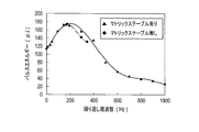
- FIG. 2 is a diagram of experimental results showing the relationship between the pulse frequency and the repetition frequency with and without the matrix table of the passive Q-switched laser of Example 1 of the present invention.
- FIG. 3 is a diagram showing a detailed example of the matrix table of the passive Q-switched laser according to the first embodiment of the present invention.
- FIG. 4 is a configuration diagram of a conventional passive Q-switched laser.
- the optimum operating conditions for passive Q-switched lasers vary depending on the repetition frequency for laser excitation. Further, the optimum operating condition of the wavelength conversion element for obtaining the third harmonic differs depending on the repetition frequency.
- the optimum operating condition includes pump power, pump pulse width, temperature of the wavelength conversion element for obtaining the second harmonic, and temperature of the wavelength conversion element for obtaining the third harmonic.
- laser and wavelength conversion inspections are performed at the factory to determine the optimum operating conditions. Based on this optimum operating condition, the pump power, pump pulse width, wavelength converter temperature for obtaining the second harmonic, and wavelength converter temperature for obtaining the third harmonic for the repetition frequency are supported.
- the attached matrix table is created in advance.
- FIG. 1 is a configuration diagram of a passive Q-switched laser according to Example 1 of the present invention.
- the passive Q switch laser of Example 1 shown in FIG. 1 includes an excitation source 1, lenses 2a and 2b, a mirror 5a, a laser medium 3, a saturable absorber 4, a mirror 5b, SHG7 and THG8, a first temperature adjusting element 9a, A second temperature adjusting element 9b, an input unit 10, and a controller 20 are provided.
- the mirror 5a, the laser medium 3, the saturable absorber 4, and the mirror 5b constitute an optical resonator.
- the first temperature adjusting element 9a is made of a Peltier element and is arranged in contact with or in the vicinity of the SHG 6, and adjusts the temperature of the SHG 6 to a predetermined temperature by a temperature control signal from the control unit 21.
- the second temperature adjusting element 9b is formed of a Peltier element and is disposed in contact with or near the THG 7 and adjusts the temperature of the THG 7 to a predetermined temperature by a temperature control signal from the control unit 21.
- the input unit 10 includes a keyboard, a mouse, a touch pal, and the like, and inputs a repetition frequency of a pulse signal for exciting a laser diode included in the excitation source 1.
- the controller 20 includes a microcomputer and includes a control unit 21 and a matrix table memory 22.
- the matrix table memory 22 is composed of a readable / writable memory, and as shown in FIG. (Corresponding to the pulse width of the present invention), the optimum value of the SHG6 temperature, and the optimum value of the THG7 temperature are stored in association with each other.
- the control unit 21 refers to the matrix table memory 22 to read out and read out the optimum value of the pump power and the optimum value of the pump pulse width of the excitation source 1 corresponding to the repetition frequency input from the input unit 10.
- the excitation source 1 is controlled so that the optimum value of the pump power of the excitation source 1 and the optimum value of the pump pulse width are obtained.
- control unit 21 refers to the matrix table memory 22 and reads out the optimum value of the temperature of SHG 6 and the optimum value of the temperature of THG 7 corresponding to the repetition frequency inputted from the input unit 10, and reads out the read SHG 6.
- a temperature control signal for controlling the temperature of SHG6 and the temperature of THG7 is output to the first temperature adjusting element 9a and the second temperature adjusting element 9b so that the optimum temperature value and the optimum temperature value of THG7 are obtained. To do.
- the control unit 21 refers to the matrix table memory 22 and reads the optimum value of the pump power and the optimum value of the pump pulse width of the excitation source 1 with respect to the repetition frequency from the input unit 10 and reads the read excitation source.
- the excitation source 1 is controlled so that the optimum value of the pump power of 1 and the optimum value of the pump pulse width are obtained.
- the control unit 21 sets the pump power to 72 W. And the excitation source 1 is controlled so that the pump pulse width is 80 ⁇ s.
- the control unit 21 refers to the matrix table memory 22 and determines the optimum values of the pump power and pulse width of the excitation source 1 corresponding to the input repetition frequency.
- the pump source 1 is controlled so that the pump power and pulse width of the pump source 1 read out and read out are optimal values. Therefore, since the excitation source 1 can always be controlled under optimum operating conditions, the repetition frequency range can be expanded, and the laser diode can be stably oscillated from a single pulse to a repetition frequency of kHz.
- FIG. 2 is a graph showing the relationship between the repetition frequency and pulse energy of the passive Q-switched laser of Example 1 without the matrix table and with the matrix table. As shown in FIG. 2, when the matrix table 22 is not used, the repetition frequency is 170 Hz to 350 Hz.
- control unit 21 refers to the matrix table memory 22 and reads out the optimum value of the temperature of SHG 6 and the optimum value of the temperature of THG 7 corresponding to the repetition frequency inputted from the input unit 10, and reads out the read SHG 6.
- a temperature control signal for controlling the temperature of SHG6 and the temperature of THG7 is output to the first temperature adjusting element 9a and the second temperature adjusting element 9b so that the optimum temperature value and the optimum temperature value of THG7 are obtained. To do. Therefore, the first temperature adjusting element 9a and the second temperature adjusting element 9b can always be controlled under the optimum operating condition, so that the wavelength can be converted under the optimum operating condition.
- the present invention is applicable to passive Q-switched lasers such as spectroscopic devices, laser processing devices, medical devices, and laser illumination devices.
Landscapes
- Physics & Mathematics (AREA)
- Electromagnetism (AREA)
- Optics & Photonics (AREA)
- Engineering & Computer Science (AREA)
- Nonlinear Science (AREA)
- Plasma & Fusion (AREA)
- General Physics & Mathematics (AREA)
- Chemical & Material Sciences (AREA)
- Crystallography & Structural Chemistry (AREA)
- Microelectronics & Electronic Packaging (AREA)
- Lasers (AREA)
- Optical Modulation, Optical Deflection, Nonlinear Optics, Optical Demodulation, Optical Logic Elements (AREA)
Abstract
Description
Claims (6)
- 繰り返し周波数で励起して励起光を出力する励起源と、
光共振器を構成する一対の反射ミラー間に配置され且つ前記励起源からの励起光により励起させてレーザ光を放出するレーザ媒質と、
前記一対の反射ミラー間に配置され且つ前記レーザ媒質からのレーザ光の吸収に伴って透過率が増加する可飽和吸収体と、
前記繰り返し周波数に対する前記励起源の出力及びパルス幅の最適値を対応付けて格納したマトリックステーブルと、
前記マトリックステーブルを参照して、入力された繰り返し周波数に対応する前記励起源の出力及びパルス幅の最適値とを読み出し、読み出された前記励起源の出力及びパルス幅の最適値になるように前記励起源を制御する制御部と、
を備える受動Qスイッチレーザ。 - 前記可飽和吸収体からのレーザ光である基本波を第2高調波に変換する第1波長変換素子と、前記第1波長変換素子からの第2高調波と残りの基本波を第3高調波に変換する第2波長変換素子とを有し、
前記マトリックステーブルは、前記繰り返し周波数に対する前記第1波長変換素子の温度の最適値と前記第2波長変換素子の温度の最適値とを対応付けて格納し、
前記制御部は、前記マトリックステーブルを参照して、入力された繰り返し周波数に対応する前記第1波長変換素子の温度の最適値と前記第2波長変換素子の温度の最適値とを読み出し、読み出された前記第1波長変換素子の温度の最適値と前記第2波長変換素子の温度の最適値とになるように前記第1波長変換素子の温度と前記第2波長変換素子の温度とを制御する請求項1記載の受動Qスイッチレーザ。 - 前記第1波長変換素子及び第2波長変換素子の各々には、温度を調整する温度調整素子が取り付けられ、前記制御部は、前記温度調整素子に対して温度を制御するための温度制御信号を出力する請求項1又は請求項2記載の受動Qスイッチレーザ。
- 前記レーザ媒質は、希土類ドープYAGからなる請求項1乃至請求項3のいずれか1項記載の受動Qスイッチレーザ。
- 前記可飽和吸収体は、Cr:YAGからなる請求項1乃至請求項4のいずれか1項記載の受動Qスイッチレーザ。
- 繰り返し周波数で励起して励起光を出力する励起源と、光共振器を構成する一対の反射ミラー間に配置され且つ前記励起源からの励起光により励起させてレーザ光を放出するレーザ媒質と、前記一対の反射ミラー間に配置され且つ前記レーザ媒質からのレーザ光の吸収に伴って透過率が増加する可飽和吸収体とを備える受動Qスイッチレーザの動作最適化方法であって、
前記繰り返し周波数に対する前記励起源の出力及びパルス幅の最適値を対応付けて格納したマトリックステーブルを作成するステップと、
前記マトリックステーブルを参照して、入力された繰り返し周波数に対応する前記励起源の出力及びパルス幅の最適値とを読み出し、読み出された前記励起源の出力及びパルス幅の最適値になるように前記励起源を制御するステップと、
を備える受動Qスイッチレーザの動作最適化方法。
Priority Applications (4)
| Application Number | Priority Date | Filing Date | Title |
|---|---|---|---|
| US15/565,607 US10153607B2 (en) | 2015-05-12 | 2015-05-12 | Passive Q-switch laser and method for optimizing action of the same |
| JP2017517510A JP6663913B2 (ja) | 2015-05-12 | 2015-05-12 | 受動qスイッチレーザ及びその動作最適化方法 |
| CN201580079390.9A CN107615599B (zh) | 2015-05-12 | 2015-05-12 | 被动q开关激光器及其动作优化方法 |
| PCT/JP2015/063593 WO2016181488A1 (ja) | 2015-05-12 | 2015-05-12 | 受動qスイッチレーザ及びその動作最適化方法 |
Applications Claiming Priority (1)
| Application Number | Priority Date | Filing Date | Title |
|---|---|---|---|
| PCT/JP2015/063593 WO2016181488A1 (ja) | 2015-05-12 | 2015-05-12 | 受動qスイッチレーザ及びその動作最適化方法 |
Publications (1)
| Publication Number | Publication Date |
|---|---|
| WO2016181488A1 true WO2016181488A1 (ja) | 2016-11-17 |
Family
ID=57247811
Family Applications (1)
| Application Number | Title | Priority Date | Filing Date |
|---|---|---|---|
| PCT/JP2015/063593 Ceased WO2016181488A1 (ja) | 2015-05-12 | 2015-05-12 | 受動qスイッチレーザ及びその動作最適化方法 |
Country Status (4)
| Country | Link |
|---|---|
| US (1) | US10153607B2 (ja) |
| JP (1) | JP6663913B2 (ja) |
| CN (1) | CN107615599B (ja) |
| WO (1) | WO2016181488A1 (ja) |
Cited By (2)
| Publication number | Priority date | Publication date | Assignee | Title |
|---|---|---|---|---|
| WO2019099179A1 (en) * | 2017-11-17 | 2019-05-23 | Cymer, Llc | Lithography system bandwidth control |
| JP2020113569A (ja) * | 2019-01-08 | 2020-07-27 | 株式会社島津製作所 | レーザ誘起ブレイクダウン分光装置 |
Families Citing this family (5)
| Publication number | Priority date | Publication date | Assignee | Title |
|---|---|---|---|---|
| JP6663913B2 (ja) * | 2015-05-12 | 2020-03-13 | 株式会社島津製作所 | 受動qスイッチレーザ及びその動作最適化方法 |
| WO2017060967A1 (ja) * | 2015-10-06 | 2017-04-13 | 株式会社島津製作所 | 波長変換装置 |
| TW202114308A (zh) * | 2019-05-21 | 2021-04-01 | 日商索尼股份有限公司 | 被動q開關雷射裝置、控制方法及雷射加工裝置 |
| JP7695838B2 (ja) * | 2021-07-30 | 2025-06-19 | 株式会社キーエンス | レーザ誘起ブレークダウン分光装置 |
| CN117526075B (zh) * | 2023-11-23 | 2024-09-03 | 无锡卓海科技股份有限公司 | 一种固体激光器及其锁模自优化方法 |
Citations (11)
| Publication number | Priority date | Publication date | Assignee | Title |
|---|---|---|---|---|
| JPS55126679U (ja) * | 1979-03-05 | 1980-09-08 | ||
| JPH0422182A (ja) * | 1990-05-17 | 1992-01-27 | Toshiba Corp | Qスイッチパルスレーザ出力装置 |
| WO1997031411A1 (en) * | 1996-02-20 | 1997-08-28 | Geotronics Ab | Stabilisation of a pulsed laser |
| JPH10256635A (ja) * | 1997-03-06 | 1998-09-25 | Toshiba Corp | 連続励起qスイッチレーザ出力装置及びレーザ加工装置 |
| JP2001305592A (ja) * | 2000-04-19 | 2001-10-31 | Mitsubishi Heavy Ind Ltd | レーザ波長変換装置 |
| WO2007064298A1 (en) * | 2005-11-29 | 2007-06-07 | Agency For Science, Technology And Research | Q-switched laser arrangement |
| JP2007294498A (ja) * | 2006-04-21 | 2007-11-08 | Sumitomo Heavy Ind Ltd | パルスレーザ装置及びパルスレーザビーム生成方法 |
| JP2008112805A (ja) * | 2006-10-30 | 2008-05-15 | Sumitomo Heavy Ind Ltd | パルスレーザ熱処理装置とその制御方法 |
| JP2008140820A (ja) * | 2006-11-30 | 2008-06-19 | Seiko Epson Corp | レーザ光源装置の駆動方法、レーザ光源装置、画像表示装置、モニタ装置、照明装置 |
| US20120069860A1 (en) * | 2008-12-03 | 2012-03-22 | V-Gen Ltd. | Gain-Switched Fiber Laser |
| JP2012084729A (ja) * | 2010-10-13 | 2012-04-26 | Hamamatsu Photonics Kk | レーザ装置 |
Family Cites Families (14)
| Publication number | Priority date | Publication date | Assignee | Title |
|---|---|---|---|---|
| US5226051A (en) * | 1991-06-04 | 1993-07-06 | Lightwave Electronics | Laser pump control for output power stabilization |
| JPH0931411A (ja) | 1995-07-24 | 1997-02-04 | Toshiba Corp | 塗料及び塗装方法 |
| US5982790A (en) | 1997-01-16 | 1999-11-09 | Lightwave Electronics Corporation | System for reducing pulse-to-pulse energy variation in a pulsed laser |
| DE19705330C1 (de) * | 1997-02-12 | 1998-02-19 | Lambda Physik Gmbh | Verfahren und Festkörperlasersystem zum Erzeugen von Laserimpulsen mit variabler Impulsfolgefrequenz und konstanten Strahleigenschaften |
| US5912912A (en) * | 1997-09-05 | 1999-06-15 | Coherent, Inc. | Repetitively-pulsed solid-state laser having resonator including multiple different gain-media |
| JP2003086873A (ja) | 2001-09-10 | 2003-03-20 | Hamamatsu Photonics Kk | 受動qスイッチレーザ |
| JP2003198019A (ja) * | 2001-12-25 | 2003-07-11 | Hamamatsu Photonics Kk | レーザ光源 |
| JP4530348B2 (ja) | 2004-09-06 | 2010-08-25 | 大学共同利用機関法人自然科学研究機構 | 受動qスイッチレーザ装置 |
| US7843978B2 (en) | 2005-02-04 | 2010-11-30 | Jds Uniphase Corporation | Passively Q-switched laser with adjustable pulse repetition rate |
| JP2008117805A (ja) | 2006-10-31 | 2008-05-22 | Toshiba Corp | プリント配線板、プリント配線板の電極形成方法およびハードディスク装置 |
| DE102007017591B4 (de) * | 2007-04-13 | 2018-11-08 | Jenoptik Laser Gmbh | Laser und Verfahren zur Erzeugung gepulster Laserstrahlung |
| US9297696B2 (en) * | 2013-01-25 | 2016-03-29 | U.S. Department Of Energy | Laser based analysis using a passively Q-switched laser employing analysis electronics and a means for detecting atomic optical emission of the laser media |
| CN104466653A (zh) * | 2014-12-29 | 2015-03-25 | 中国科学院半导体研究所 | 重复频率可控的被动调q产生激光脉冲的方法 |
| JP6663913B2 (ja) * | 2015-05-12 | 2020-03-13 | 株式会社島津製作所 | 受動qスイッチレーザ及びその動作最適化方法 |
-
2015
- 2015-05-12 JP JP2017517510A patent/JP6663913B2/ja active Active
- 2015-05-12 US US15/565,607 patent/US10153607B2/en active Active
- 2015-05-12 CN CN201580079390.9A patent/CN107615599B/zh not_active Expired - Fee Related
- 2015-05-12 WO PCT/JP2015/063593 patent/WO2016181488A1/ja not_active Ceased
Patent Citations (11)
| Publication number | Priority date | Publication date | Assignee | Title |
|---|---|---|---|---|
| JPS55126679U (ja) * | 1979-03-05 | 1980-09-08 | ||
| JPH0422182A (ja) * | 1990-05-17 | 1992-01-27 | Toshiba Corp | Qスイッチパルスレーザ出力装置 |
| WO1997031411A1 (en) * | 1996-02-20 | 1997-08-28 | Geotronics Ab | Stabilisation of a pulsed laser |
| JPH10256635A (ja) * | 1997-03-06 | 1998-09-25 | Toshiba Corp | 連続励起qスイッチレーザ出力装置及びレーザ加工装置 |
| JP2001305592A (ja) * | 2000-04-19 | 2001-10-31 | Mitsubishi Heavy Ind Ltd | レーザ波長変換装置 |
| WO2007064298A1 (en) * | 2005-11-29 | 2007-06-07 | Agency For Science, Technology And Research | Q-switched laser arrangement |
| JP2007294498A (ja) * | 2006-04-21 | 2007-11-08 | Sumitomo Heavy Ind Ltd | パルスレーザ装置及びパルスレーザビーム生成方法 |
| JP2008112805A (ja) * | 2006-10-30 | 2008-05-15 | Sumitomo Heavy Ind Ltd | パルスレーザ熱処理装置とその制御方法 |
| JP2008140820A (ja) * | 2006-11-30 | 2008-06-19 | Seiko Epson Corp | レーザ光源装置の駆動方法、レーザ光源装置、画像表示装置、モニタ装置、照明装置 |
| US20120069860A1 (en) * | 2008-12-03 | 2012-03-22 | V-Gen Ltd. | Gain-Switched Fiber Laser |
| JP2012084729A (ja) * | 2010-10-13 | 2012-04-26 | Hamamatsu Photonics Kk | レーザ装置 |
Cited By (4)
| Publication number | Priority date | Publication date | Assignee | Title |
|---|---|---|---|---|
| WO2019099179A1 (en) * | 2017-11-17 | 2019-05-23 | Cymer, Llc | Lithography system bandwidth control |
| US10833471B2 (en) | 2017-11-17 | 2020-11-10 | Cymer, Llc | Lithography system bandwidth control |
| US11769982B2 (en) | 2017-11-17 | 2023-09-26 | Cymer, Llc | Lithography system bandwidth control |
| JP2020113569A (ja) * | 2019-01-08 | 2020-07-27 | 株式会社島津製作所 | レーザ誘起ブレイクダウン分光装置 |
Also Published As
| Publication number | Publication date |
|---|---|
| JP6663913B2 (ja) | 2020-03-13 |
| US10153607B2 (en) | 2018-12-11 |
| CN107615599B (zh) | 2019-12-10 |
| US20180123310A1 (en) | 2018-05-03 |
| JPWO2016181488A1 (ja) | 2017-12-14 |
| CN107615599A (zh) | 2018-01-19 |
Similar Documents
| Publication | Publication Date | Title |
|---|---|---|
| JP6663913B2 (ja) | 受動qスイッチレーザ及びその動作最適化方法 | |
| US6931047B2 (en) | Laser light source | |
| JP2009253068A (ja) | レーザ発振器及びレーザ加工装置 | |
| JPWO2017060967A1 (ja) | 波長変換装置 | |
| JPWO2007138884A1 (ja) | レーザパルス発生装置及び方法並びにレーザ加工装置及び方法 | |
| WO2013084608A1 (ja) | Co2レーザ装置およびco2レーザ加工装置 | |
| JP6862106B2 (ja) | 電流制御装置及びレーザ装置 | |
| JP2011521447A (ja) | キャビティ内周波数二倍化結合キャビティダイオード励起ndレーザによってポンピングされたルビーレーザのキャビティ内第2高調波発生 | |
| KR20150087933A (ko) | 고출력 극초단 펄스 레이저 장치 | |
| JP7079953B2 (ja) | 波長変換方法、波長変換装置及びレーザ光源装置 | |
| TW569509B (en) | Barium fluoride high repetition rate UV excimer laser | |
| JP6376224B2 (ja) | 受動qスイッチレーザ | |
| JP2012038895A (ja) | ファイバレーザ光源およびそれを用いた波長変換レーザ光源 | |
| JP5024118B2 (ja) | レーザ発振方法、レーザ、レーザ加工方法、及びレーザ測定方法 | |
| JP2017528911A5 (ja) | ||
| JP4071806B2 (ja) | 波長変換装置 | |
| JP2009176944A (ja) | ファイバーレーザ装置及び制御方法 | |
| JP2002368312A (ja) | 極短パルスレーザ | |
| JP3700516B2 (ja) | 波長変換レーザ装置およびレーザ加工装置 | |
| JP2017204592A (ja) | 受動qスイッチレーザ | |
| JP2020043280A (ja) | 受動qスイッチレーザ装置 | |
| JP6919287B2 (ja) | 固体レーザ装置 | |
| JP4146207B2 (ja) | 非線型波長変換レーザ装置 | |
| JP2022115742A (ja) | 固体レーザ | |
| JP2006324601A (ja) | レーザ装置及びレーザ加工装置 |
Legal Events
| Date | Code | Title | Description |
|---|---|---|---|
| 121 | Ep: the epo has been informed by wipo that ep was designated in this application |
Ref document number: 15891813 Country of ref document: EP Kind code of ref document: A1 |
|
| ENP | Entry into the national phase |
Ref document number: 2017517510 Country of ref document: JP Kind code of ref document: A |
|
| WWE | Wipo information: entry into national phase |
Ref document number: 15565607 Country of ref document: US |
|
| NENP | Non-entry into the national phase |
Ref country code: DE |
|
| 122 | Ep: pct application non-entry in european phase |
Ref document number: 15891813 Country of ref document: EP Kind code of ref document: A1 |