WO2016175121A1 - 無方向性電磁鋼板 - Google Patents
無方向性電磁鋼板 Download PDFInfo
- Publication number
- WO2016175121A1 WO2016175121A1 PCT/JP2016/062626 JP2016062626W WO2016175121A1 WO 2016175121 A1 WO2016175121 A1 WO 2016175121A1 JP 2016062626 W JP2016062626 W JP 2016062626W WO 2016175121 A1 WO2016175121 A1 WO 2016175121A1
- Authority
- WO
- WIPO (PCT)
- Prior art keywords
- particles
- steel sheet
- metal
- temperature
- ferrite grains
- Prior art date
Links
Images


Classifications
-
- C—CHEMISTRY; METALLURGY
- C22—METALLURGY; FERROUS OR NON-FERROUS ALLOYS; TREATMENT OF ALLOYS OR NON-FERROUS METALS
- C22C—ALLOYS
- C22C38/00—Ferrous alloys, e.g. steel alloys
- C22C38/60—Ferrous alloys, e.g. steel alloys containing lead, selenium, tellurium, or antimony, or more than 0.04% by weight of sulfur
-
- C—CHEMISTRY; METALLURGY
- C21—METALLURGY OF IRON
- C21D—MODIFYING THE PHYSICAL STRUCTURE OF FERROUS METALS; GENERAL DEVICES FOR HEAT TREATMENT OF FERROUS OR NON-FERROUS METALS OR ALLOYS; MAKING METAL MALLEABLE, e.g. BY DECARBURISATION OR TEMPERING
- C21D8/00—Modifying the physical properties by deformation combined with, or followed by, heat treatment
- C21D8/12—Modifying the physical properties by deformation combined with, or followed by, heat treatment during manufacturing of articles with special electromagnetic properties
- C21D8/1244—Modifying the physical properties by deformation combined with, or followed by, heat treatment during manufacturing of articles with special electromagnetic properties the heat treatment(s) being of interest
- C21D8/1272—Final recrystallisation annealing
-
- C—CHEMISTRY; METALLURGY
- C21—METALLURGY OF IRON
- C21D—MODIFYING THE PHYSICAL STRUCTURE OF FERROUS METALS; GENERAL DEVICES FOR HEAT TREATMENT OF FERROUS OR NON-FERROUS METALS OR ALLOYS; MAKING METAL MALLEABLE, e.g. BY DECARBURISATION OR TEMPERING
- C21D9/00—Heat treatment, e.g. annealing, hardening, quenching or tempering, adapted for particular articles; Furnaces therefor
- C21D9/46—Heat treatment, e.g. annealing, hardening, quenching or tempering, adapted for particular articles; Furnaces therefor for sheet metals
-
- C—CHEMISTRY; METALLURGY
- C22—METALLURGY; FERROUS OR NON-FERROUS ALLOYS; TREATMENT OF ALLOYS OR NON-FERROUS METALS
- C22C—ALLOYS
- C22C38/00—Ferrous alloys, e.g. steel alloys
-
- C—CHEMISTRY; METALLURGY
- C22—METALLURGY; FERROUS OR NON-FERROUS ALLOYS; TREATMENT OF ALLOYS OR NON-FERROUS METALS
- C22C—ALLOYS
- C22C38/00—Ferrous alloys, e.g. steel alloys
- C22C38/001—Ferrous alloys, e.g. steel alloys containing N
-
- C—CHEMISTRY; METALLURGY
- C22—METALLURGY; FERROUS OR NON-FERROUS ALLOYS; TREATMENT OF ALLOYS OR NON-FERROUS METALS
- C22C—ALLOYS
- C22C38/00—Ferrous alloys, e.g. steel alloys
- C22C38/002—Ferrous alloys, e.g. steel alloys containing In, Mg, or other elements not provided for in one single group C22C38/001 - C22C38/60
-
- C—CHEMISTRY; METALLURGY
- C22—METALLURGY; FERROUS OR NON-FERROUS ALLOYS; TREATMENT OF ALLOYS OR NON-FERROUS METALS
- C22C—ALLOYS
- C22C38/00—Ferrous alloys, e.g. steel alloys
- C22C38/004—Very low carbon steels, i.e. having a carbon content of less than 0,01%
-
- C—CHEMISTRY; METALLURGY
- C22—METALLURGY; FERROUS OR NON-FERROUS ALLOYS; TREATMENT OF ALLOYS OR NON-FERROUS METALS
- C22C—ALLOYS
- C22C38/00—Ferrous alloys, e.g. steel alloys
- C22C38/005—Ferrous alloys, e.g. steel alloys containing rare earths, i.e. Sc, Y, Lanthanides
-
- C—CHEMISTRY; METALLURGY
- C22—METALLURGY; FERROUS OR NON-FERROUS ALLOYS; TREATMENT OF ALLOYS OR NON-FERROUS METALS
- C22C—ALLOYS
- C22C38/00—Ferrous alloys, e.g. steel alloys
- C22C38/008—Ferrous alloys, e.g. steel alloys containing tin
-
- C—CHEMISTRY; METALLURGY
- C22—METALLURGY; FERROUS OR NON-FERROUS ALLOYS; TREATMENT OF ALLOYS OR NON-FERROUS METALS
- C22C—ALLOYS
- C22C38/00—Ferrous alloys, e.g. steel alloys
- C22C38/02—Ferrous alloys, e.g. steel alloys containing silicon
-
- C—CHEMISTRY; METALLURGY
- C22—METALLURGY; FERROUS OR NON-FERROUS ALLOYS; TREATMENT OF ALLOYS OR NON-FERROUS METALS
- C22C—ALLOYS
- C22C38/00—Ferrous alloys, e.g. steel alloys
- C22C38/04—Ferrous alloys, e.g. steel alloys containing manganese
-
- C—CHEMISTRY; METALLURGY
- C22—METALLURGY; FERROUS OR NON-FERROUS ALLOYS; TREATMENT OF ALLOYS OR NON-FERROUS METALS
- C22C—ALLOYS
- C22C38/00—Ferrous alloys, e.g. steel alloys
- C22C38/06—Ferrous alloys, e.g. steel alloys containing aluminium
-
- C—CHEMISTRY; METALLURGY
- C22—METALLURGY; FERROUS OR NON-FERROUS ALLOYS; TREATMENT OF ALLOYS OR NON-FERROUS METALS
- C22C—ALLOYS
- C22C38/00—Ferrous alloys, e.g. steel alloys
- C22C38/08—Ferrous alloys, e.g. steel alloys containing nickel
-
- C—CHEMISTRY; METALLURGY
- C22—METALLURGY; FERROUS OR NON-FERROUS ALLOYS; TREATMENT OF ALLOYS OR NON-FERROUS METALS
- C22C—ALLOYS
- C22C38/00—Ferrous alloys, e.g. steel alloys
- C22C38/12—Ferrous alloys, e.g. steel alloys containing tungsten, tantalum, molybdenum, vanadium, or niobium
-
- C—CHEMISTRY; METALLURGY
- C22—METALLURGY; FERROUS OR NON-FERROUS ALLOYS; TREATMENT OF ALLOYS OR NON-FERROUS METALS
- C22C—ALLOYS
- C22C38/00—Ferrous alloys, e.g. steel alloys
- C22C38/14—Ferrous alloys, e.g. steel alloys containing titanium or zirconium
-
- C—CHEMISTRY; METALLURGY
- C22—METALLURGY; FERROUS OR NON-FERROUS ALLOYS; TREATMENT OF ALLOYS OR NON-FERROUS METALS
- C22C—ALLOYS
- C22C38/00—Ferrous alloys, e.g. steel alloys
- C22C38/16—Ferrous alloys, e.g. steel alloys containing copper
-
- H—ELECTRICITY
- H01—ELECTRIC ELEMENTS
- H01F—MAGNETS; INDUCTANCES; TRANSFORMERS; SELECTION OF MATERIALS FOR THEIR MAGNETIC PROPERTIES
- H01F1/00—Magnets or magnetic bodies characterised by the magnetic materials therefor; Selection of materials for their magnetic properties
- H01F1/01—Magnets or magnetic bodies characterised by the magnetic materials therefor; Selection of materials for their magnetic properties of inorganic materials
- H01F1/03—Magnets or magnetic bodies characterised by the magnetic materials therefor; Selection of materials for their magnetic properties of inorganic materials characterised by their coercivity
- H01F1/12—Magnets or magnetic bodies characterised by the magnetic materials therefor; Selection of materials for their magnetic properties of inorganic materials characterised by their coercivity of soft-magnetic materials
- H01F1/14—Magnets or magnetic bodies characterised by the magnetic materials therefor; Selection of materials for their magnetic properties of inorganic materials characterised by their coercivity of soft-magnetic materials metals or alloys
- H01F1/147—Alloys characterised by their composition
- H01F1/14766—Fe-Si based alloys
- H01F1/14791—Fe-Si-Al based alloys, e.g. Sendust
-
- H—ELECTRICITY
- H01—ELECTRIC ELEMENTS
- H01F—MAGNETS; INDUCTANCES; TRANSFORMERS; SELECTION OF MATERIALS FOR THEIR MAGNETIC PROPERTIES
- H01F1/00—Magnets or magnetic bodies characterised by the magnetic materials therefor; Selection of materials for their magnetic properties
- H01F1/01—Magnets or magnetic bodies characterised by the magnetic materials therefor; Selection of materials for their magnetic properties of inorganic materials
- H01F1/03—Magnets or magnetic bodies characterised by the magnetic materials therefor; Selection of materials for their magnetic properties of inorganic materials characterised by their coercivity
- H01F1/12—Magnets or magnetic bodies characterised by the magnetic materials therefor; Selection of materials for their magnetic properties of inorganic materials characterised by their coercivity of soft-magnetic materials
- H01F1/14—Magnets or magnetic bodies characterised by the magnetic materials therefor; Selection of materials for their magnetic properties of inorganic materials characterised by their coercivity of soft-magnetic materials metals or alloys
- H01F1/16—Magnets or magnetic bodies characterised by the magnetic materials therefor; Selection of materials for their magnetic properties of inorganic materials characterised by their coercivity of soft-magnetic materials metals or alloys in the form of sheets
-
- C—CHEMISTRY; METALLURGY
- C21—METALLURGY OF IRON
- C21D—MODIFYING THE PHYSICAL STRUCTURE OF FERROUS METALS; GENERAL DEVICES FOR HEAT TREATMENT OF FERROUS OR NON-FERROUS METALS OR ALLOYS; MAKING METAL MALLEABLE, e.g. BY DECARBURISATION OR TEMPERING
- C21D2211/00—Microstructure comprising significant phases
- C21D2211/005—Ferrite
Definitions
- the present invention relates to a non-oriented electrical steel sheet used as a core material for drive motors of electric vehicles and motors for various electric devices.
- the material for the rotor of the motor is required to have excellent magnetic properties and mechanical strength to withstand centrifugal force and stress fluctuation.
- high fatigue strength is required, but generally, the higher the tensile strength TS, the better the fatigue strength.
- Patent Documents 1 to 4 As a method of achieving both low iron loss and high strength, a method of increasing the strength of a steel sheet by finely precipitating metallic Cu particles after cold rolling recrystallization. Has been proposed. It is possible to achieve both low iron loss and high strength by coarsening the recrystallized grains and precipitating fine Cu that does not affect the domain wall movement.
- An object of the present invention is to improve the fatigue characteristics of a low iron loss non-oriented electrical steel sheet on which metal Cu particles are deposited, and to provide a low iron loss non-oriented electrical steel sheet and a method for producing the same.
- the purpose is to provide.
- the present inventors diligently studied a method for solving the above problems. As a result, it has been found that a high tensile strength and a high fatigue strength can be realized while maintaining good magnetic properties by properly combining the hot rolling conditions and the Cu precipitation conditions.
- the present invention has been made based on the above findings, and the gist thereof is as follows.
- the non-oriented electrical steel sheet according to one aspect of the present invention has a component composition of unit mass%, C: 0 to 0.0100%, Si: 1.00 to 4.00%, Mn: 0.00. 05 to 1.00%, Al: 0.10 to 3.00%, Cu: 0.50 to 2.00% Ni: 0 to 3.00%, Ca: 0 to 0.0100%, REM: 0 to 0.0100%, Sn: 0 to 0.3%, Sb: 0 to 0.3%, S: 0 to 0.01%, P: 0 to 0.01%, N: 0 to 0.01%, O: 0 to 0.01%, Ti: 0 to 0.01%, Nb: 0 to 0.01%, V: 0 to 0.01%, Zr: 0 to 0.01%, and Mg: 0 to Containing ferrite grains containing 0.01%, the balance consisting of Fe and impurities, and having a structure of 99.0 area% or more and containing no unrecrystallized structure, and the
- the average particle size of the metal Cu particles inside the ferrite particles is 2.0 nm or more and 10.0 nm or less.
- the component composition is Ni: 0.50 to 3.00%, Ca: 0.0005 to 0.0100%, REM: One or more selected from the group consisting of 0.0005 to 0.0100% may be contained.
- a non-oriented electrical steel sheet with low iron loss and excellent fatigue characteristics can be manufactured and provided.
- the present invention can contribute to high speed and high efficiency of the motor.
- the recrystallized steel sheet was 20 ° C./second to obtain a recrystallized steel sheet. Further thereafter, the recrystallized steel sheet was subjected to Cu precipitation annealing at various soaking temperatures within a range of 400 to 700 ° C. for 60 seconds soaking time to obtain a steel sheet for evaluation.
- a JIS No. 5 tensile test piece was cut out from the evaluation steel plate, and a tensile test was performed based on JIS Z 2241 “Metal Material Tensile Test Method”. The longitudinal direction of the tensile test piece was matched with the rolling direction of the steel plate for evaluation. Further, based on JIS Z 2273 “General Rules for Fatigue Testing Methods for Metal Materials”, the fatigue test pieces shown in FIGS. 1-1 and 1-2 were cut out from the steel plate for evaluation and subjected to fatigue tests by partial piece swing tension.
- A, b, c, e, R, w, W, X, Y 0 , Z, and ⁇ shown in FIGS. 1-1 and 1-2 were as follows.
- the surface of the constricted portion of the test piece was subjected to surface finishing with 600th paper.
- the longitudinal direction of the fatigue test piece was matched with the rolling direction of the steel plate for evaluation.
- the minimum load was fixed at 3 kgf
- the frequency was 20 Hz
- the maximum stress when the repeated stress was 2 million times and not broken was defined as the fatigue strength FS of the steel plate for evaluation.
- a 55 mm ⁇ 55 mm single plate sample for magnetic measurement was cut out from the evaluation steel plate, and the average iron loss in the direction perpendicular to the rolling direction was evaluated based on JIS C 2556 “Electromagnetic steel plate single plate magnetic property test method”. The evaluation was performed under conditions of a frequency of 400 Hz and a magnetic flux density of 1.0T.
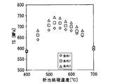
- FIG. 2 shows the relationship between the precipitation treatment temperature (Cu precipitation treatment temperature) and tensile strength TS in Cu precipitation annealing
- FIG. 3 shows the relationship between the precipitation treatment temperature and fatigue strength FS. 2 and 3, in hot rolling condition 1 shown in Table 1, the Cu precipitation treatment temperature at which TS (tensile strength) is highest is 525 to 550 ° C., and Cu precipitation at which FS (fatigue strength) is highest. It can be seen that the processing temperature is 575 to 600 ° C.
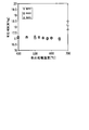
- FIG. 4 shows the relationship between the Cu deposition treatment temperature and the iron loss W 10/400 .
- the Cu precipitation treatment temperature is 700 ° C.
- the iron loss slightly increases, but when the Cu precipitation treatment temperature is 650 ° C. or less, the influence of the Cu precipitation treatment temperature on the iron loss is small. This can be seen from FIG.
- the present inventors permeate the Cu precipitation form in the ferrite crystal grains of the test material. It was investigated with a scanning electron microscope (TEM). Under hot rolling condition 1 and Cu precipitation treatment temperature of 550 ° C., the average precipitation particle size of Cu was 2.3 nm, and the crystal structure of all observed Cu particles was BCC. Under hot rolling condition 3 and Cu precipitation treatment temperature of 650 ° C., the average precipitation particle size of Cu was 7 nm, and the crystal structure of Cu particles was observed to be 9R structure and FCC structure as well as BCC structure.
- TEM scanning electron microscope
- Table 3 shows 9R for the average particle diameter of precipitated Cu particles, the number density per volume, and the number density of all precipitated Cu particles when the hot rolling conditions and the Cu precipitation treatment temperature are changed.
- the ratio of the number density of particles and the ratio of the number density of BCC particles are shown. Comparing the fatigue strength in FIG. 3 and the Cu precipitation state in Table 3, it was found that the 9R structure particles were included together with the BCC structure Cu particles under the high fatigue strength conditions in each hot rolling condition. Furthermore, it was found that the number density of Cu particles was higher in hot rolling conditions 2 and 3 having higher TS and FS than in hot rolling condition 1 even under the same Cu precipitation annealing conditions.
- Cu particles in ⁇ -Fe change the crystal structure as the precipitation size increases and change the consistency with Fe as a matrix. That is, at the initial stage of precipitation, Cu precipitates in a BCC structure that matches the matrix, and suppresses an increase in energy at the interface. When slightly grown, it takes a crystal structure of 9R structure close to the originally stable FCC structure, and is in a semi-matched state with the matrix. When the temperature further increases, the structure changes to an FCC structure which is a stable phase, and becomes completely inconsistent with the matrix.
- the 9R structure refers to FIG. As shown in FIG. 4, it is a long-period structure in which the stacking period of the closest packed surface of atoms is nine layers.
- Fatigue strength increases when Cu particles with 9R structure are included. This is because in the case of Cu particles having a BCC structure aligned with the matrix, cutting of the Cu particles occurs due to repeated stress, but in the case of Cu particles having a semi-aligned 9R structure, cutting is difficult to occur. Guessed. Furthermore, Cu particles with BCC structure do not suppress dislocation movement, so it does not affect the mechanical strength of the steel sheet, but 9R structure Cu particles suppress movement of dislocation, so the mechanical strength (for example, tensile strength) of the steel sheet is reduced. It is presumed to have a function to improve.
- the number density of Cu particles can be increased even if the size of Cu particles is increased to some extent by reducing FOT, FT, and CT during hot rolling. It can be seen that many can be kept. That is, by reducing FOT, FT, and CT during hot rolling, it is possible to increase the number density of particles while including 9R-structured particles in the steel sheet.
- % related to the component composition means mass%.
- C 0 to 0.0100% C is an element harmful to the electromagnetic steel sheet because it increases the iron loss of the electromagnetic steel sheet and also causes magnetic aging.
- the C content is preferably 0.0050% or less, or 0.0030% or less. Since the steel plate according to this embodiment does not require C, the lower limit value of the C content is 0%. However, significant costs may be required to remove C. Therefore, the C content may be more than 0%, 0.0001% or more, 0.0005% or more, or 0.0010% or more.
- Si 1.00 to 4.00%
- Si is an element that contributes to reducing the iron loss of the electrical steel sheet by increasing the specific resistance of the steel.
- the Si content is set to 1.00% or more.
- the Si content is preferably 2.00% or more, 2.20% or more, or 2.50% or more.
- the Si content exceeds 4.00%, the steel becomes brittle, and troubles such as flaws and cracks are likely to occur during rolling. Therefore, the Si content is 4.00% or less.
- the Si content is preferably 3.60% or less, or 3.50% or less, or 3.40% or less.
- Mn 0.05 to 1.00%
- Mn is an element that increases the specific resistance of the steel and also acts to coarsen the sulfide to render it harmless.
- the Mn content is set to 0.05% or more.
- the Mn content is preferably 0.10% or more, 0.15% or more, or 0.20% or more.
- the Mn content exceeds 1.00%, the steel becomes brittle, and troubles such as flaws and cracks are likely to occur during rolling. Therefore, the Mn content is 1.00% or less.
- the Mn content is preferably 0.90% or less, 0.80% or less, or 0.70% or less.
- Al 0.10 to 3.00%
- Al is an element having a deoxidizing effect and preventing fine precipitation of nitrides by precipitating as large AlN.
- Al like Si and Mn, is an element that increases the specific resistance of steel and contributes to the reduction of iron loss.
- the Al content is set to 0.10% or more.
- the Al content is preferably 0.15% or more, 0.20% or more, or 0.30% or more.
- the Al content exceeds 3.00%, the steel becomes brittle and troubles such as wrinkles and cracks are likely to occur during rolling, so the Al content is 3.00% or less.
- the Al content is preferably 2.00% or less, 1.50% or less, or 1.20% or less.
- Cu 0.50 to 2.00% Cu is an important element in the steel sheet according to the present embodiment.
- the yield strength (YS), tensile strength (TS), and fatigue strength (FS) of the steel plate are improved without increasing the iron loss of the steel plate.
- the Cu content is set to 0.50% or more.
- the Cu content is preferably 0.80% or more, 0.90% or more, or 1.00% or more.
- the Cu content exceeds 2.00%, the steel plate is wrinkled and cracked during hot rolling of the steel plate, so the Cu content is 2.00% or less.
- the Cu content is preferably 1.80% or less, 1.60% or less, or 1.40% or less.
- the steel sheet according to the present embodiment may include one or more selected from the group consisting of Ni, Ca, and REM in addition to the elements described above. Moreover, the steel plate according to the present embodiment may include Sn and Sb in addition to the elements described above. However, even when Ni, Ca, REM, Sn, and Sb are not included, the steel sheet according to the present embodiment has good characteristics, so the lower limit value of each of Ni, Ca, REM, Sn, and Sb is 0%. is there.
- Ni 0 to 3.00%
- Ni has the effect of reducing the wrinkles of the hot-rolled steel sheet, and is also effective in increasing the mechanical strength of the steel sheet by solid solution strengthening, so Ni may be contained in the steel sheet according to this embodiment.
- the Ni content is preferably 0.50% or more, more preferably 0.80% or more, or 1.00% or more.
- the Ni content is preferably 3.00% or less, more preferably 2.60% or less, or 2.00% or less. preferable.
- Ca and REM detoxify S, which is an element that increases the iron loss of the steel sheet, by forming S in the steel as an inclusion such as oxysulfide in the cooling stage in casting.
- each of Ca and REM may be contained by 0.0005% or more.
- the more preferable lower limit of the content of each of Ca and REM is 0.0010% or 0.0030%.
- the content of Ca and REM is excessive, the amount of inclusions containing Ca and REM increases, and iron loss is deteriorated.
- the upper limit of the content of each of Ca and REM is preferably 0.0100%, and more preferably 0.009% or 0.008%.
- the term “REM” refers to a total of 17 elements composed of Sc, Y, and a lanthanoid, and the “content of REM” means the total content of these 17 elements.
- Sn 0 to 0.30%
- Sb 0 to 0.30%
- the lower limit value of each content of Sn and Sb is preferably 0.03%, more preferably 0.04% or 0.05%.
- the upper limit value of each content of Sn and Sb is preferably 0.30%, 0.20% or 0.15% Is more preferable.
- the steel plate according to the present embodiment may include one or more selected from the group consisting of S, P, N, O, Ti, Nb, V, Zr, Mg, and the like in addition to the elements described above.
- the lower limit of the content of each of these elements is 0%.
- these elements form precipitates and increase the iron loss of the steel sheet. Therefore, when these elements are contained, the upper limit of the content of each of these elements is preferably 0.010%, More preferably, it is 0.005% or 0.003%.
- the balance of the chemical components of the steel sheet according to this embodiment is iron (Fe) and impurities.
- Impurities are raw materials such as ore or scrap, or components mixed into the steel sheet due to various factors in the manufacturing process, and are allowed within a range that does not adversely affect the various characteristics of the steel sheet according to this embodiment. Means.
- a steel sheet according to the present embodiment has a structure composed of ferrite grains that do not contain an unrecrystallized structure, and contains metal Cu particles precipitated in the ferrite grains. This steel sheet has both high loss and high fatigue strength.
- the structure of the steel plate according to this embodiment and the precipitation state of the metal Cu particles will be described below.
- Ferrite grains not containing non-recrystallized structure 99.0 area% or more
- the iron loss of the steel sheet increases remarkably. Therefore, it is necessary to make almost all of the structure of the steel sheet according to the present embodiment ferrite and to recrystallize almost all of this ferrite.
- the inclusion of a structure other than about 1.0 area% other than ferrite grains not containing an unrecrystallized structure and inclusions is allowed. Therefore, the structure of the steel sheet according to this embodiment is defined as including 99.0 area% or more of ferrite grains that do not include an unrecrystallized structure.
- Whether or not the ferrite grains are recrystallized can be confirmed by a method of observing a normal metal structure. That is, after polishing the cross section of the steel sheet, when the polished surface is corroded with a corrosive liquid such as a nital liquid, the recrystallized ferrite grains are observed as bright plain crystal grains. On the other hand, an irregular dark pattern is observed in the non-recrystallized ferrite grains.
- Average grain size of ferrite grains 30-180 ⁇ m
- the average grain size of the ferrite grains needs to be 30 ⁇ m or more in order to reduce the hysteresis loss of the steel sheet.
- the average crystal grain size of the ferrite grains is set to 180 ⁇ m or less.
- the lower limit of the average grain size of the ferrite grains is preferably 30 ⁇ m, 50 ⁇ m, or 70 ⁇ m.
- the upper limit value of the average grain size of the ferrite grains is preferably 170 ⁇ m, 160 ⁇ m, or 150 ⁇ m.
- the average grain size of ferrite grains can be determined according to JIS G 0551 “Steel—Microscopic Test Method for Grain Size”. Since the average crystal grain size of the ferrite grains of the steel sheet according to the present embodiment is constant regardless of the direction of the cut surface where the grain size measurement is performed, the direction of cutting the steel sheet when measuring the average grain diameter of the ferrite grains Is not limited.
- the metal Cu particle of the steel sheet according to the present embodiment means a particle that substantially does not form an alloy or an intermetallic compound with Fe as a base material and is substantially composed only of Cu.
- the average grain size is 2.0 nm or more and 10.0 nm, and the number density measured in the ferrite grains is 10,000 to 10,000,000 / ⁇ m 3.
- Metal Cu particles are included. Furthermore, from the above-mentioned experiment and the result, in the steel plate according to the present embodiment, it is defined that 2% or more of the metal Cu particles precipitated in the ferrite grains have a 9R structure. Below, the state of the metal Cu particle
- the state of the metal Cu particles in the ferrite grain is defined, and the state of the metal particle at the ferrite grain boundary is not limited.
- the present inventors greatly influence the mechanical properties of the steel sheet according to the present embodiment, while the metal Cu particles in the ferrite grains influence the mechanical properties of the steel sheet according to the present embodiment. I found the impact to be negligible. If the amount of metal Cu particles in the ferrite grain boundary is too large, the amount of metal Cu particles in the ferrite grain may decrease, but this problem is limited as long as the state of the metal Cu particles in the ferrite grain is within the specified range. Can be ignored. Therefore, in the steel plate according to this embodiment, only the state of the metal Cu particles in the ferrite grains is defined.
- the term “metal Cu particles in ferrite grains” may be abbreviated as “metal Cu particles”.
- the metal Cu particles of the steel sheet according to the present embodiment are provided as means for preventing the movement of dislocations.
- metal Cu particles having a particle size that is too small have a low resistance to dislocation movement. Therefore, when the average particle diameter of the metal Cu particles is too small, the dislocations can be easily moved.
- the metal Cu particles having a large particle size have a high resistance to dislocation movement, but if the average particle size of the metal Cu particles is too large, the number density of the metal Cu particles decreases, and the interparticle distance increases. , Dislocation movement becomes easy. When dislocations move easily, YP, TS, and FS decrease.
- the metal Cu particles having a particle diameter of about 100 nm or more which is about the thickness of the domain wall, hinder the domain wall movement and increase the hysteresis loss. Therefore, when the average particle diameter of the metal Cu particles is too large, the iron loss becomes poor.
- the average particle size of the metal Cu precipitated particles is 10.0 nm or less, the defect of iron loss due to the metal Cu precipitated particles having a particle size of 100 nm or more may be within an allowable range. all right. Therefore, the average particle diameter of the metal Cu precipitated particles is 2.0 nm or more and 10.0 nm or less.
- the average particle diameter of the metal Cu precipitated particles is preferably 2.2 nm or more, more preferably 2.4 nm or more, and further preferably 2.5 nm or more. Moreover, the average particle diameter of the metal Cu precipitated particles is preferably 9.0 nm or less, more preferably 8.0 nm or less, and even more preferably 7.0 nm or less.
- the average particle diameter of the metal Cu particles in the ferrite grains of the steel sheet according to this embodiment is an arithmetic average of the equivalent circle diameters of the metal Cu particles in all ferrite grains having a particle diameter of 2.0 nm or more.
- the average particle diameter of the metal Cu particles is determined using a bright field image of a transmission electron microscope (TEM). The area of each Cu particle in the image is obtained, and the diameter of the circle having the area (circle equivalent diameter) is regarded as the diameter of each particle.
- TEM transmission electron microscope
- Number density of metallic Cu particles in ferrite grains 10,000 to 10,000,000 / ⁇ m 3
- the number of metallic Cu particles per unit volume depends on the Cu content, the state before the deposition treatment, and the deposition size.
- the number of metal Cu particles per 1 ⁇ m 3 volume in the ferrite grains is 10,000 / ⁇ m 3 or more in order to obtain high fatigue strength.
- it is 100,000 / ⁇ m 3 or more, more preferably 500,000 / ⁇ m 3 or more.
- the lower limit of the number density of the metal Cu particles in the ferrite grains is set to 10,000,000 / ⁇ m 3 or less.
- the number density of the metal Cu particles in the ferrite grains of the steel sheet according to the present embodiment is the number density of the metal Cu particles in all the ferrite grains having a particle diameter of 2.0 nm or more. Metal Cu particles having a particle size of less than 2.0 nm are difficult to detect and are not considered to be measured because they are considered to have substantially no effect on the characteristics of the steel sheet according to this embodiment.
- Ratio of the number density of metal Cu particles having a particle size of 2.0 nm or more having a BCC structure in ferrite grains to the number density of metal Cu particles having a particle size of 2.0 nm or more in ferrite grains (BCC particle ratio): 0% ⁇ 98%
- the present inventors have found that the type of crystal structure of the metal Cu particles affects the resistance of the metal Cu particles to dislocation movement.
- Metal Cu particles having a 9R structure (9R particles) have high resistance to dislocation movement in ferrite. This is because the ferrite crystal structure around the metal Cu particles is BCC. Dislocations are unlikely to pass through the interface of particles having different crystal structures. Therefore, the interface between the 9R particles and the ferrite having the BCC structure serves as a resistance to dislocation movement in the ferrite. On the other hand, the interface between metal Cu particles (BCC particles) having a BCC structure and ferrite does not work as a resistance to dislocations moving in the ferrite. Therefore, the BCC particles have a low resistance to dislocation movement within the ferrite.
- the 9R particle ratio of the steel sheet according to this embodiment is 2% or more.
- the 9R particle ratio is preferably 10% or more, 20% or more, or 30% or more.
- the 9R particle ratio may be 100%.
- the BCC particle ratio is set to 98% or less. Preferably, it is 90% or less, 80% or less, or 70% or less.
- the BCC particle ratio may be 0%.
- the crystal structure of the metal Cu particles may be FCC.
- FCC particles 9R particles, BCC particles, and metal Cu particles having an FCC structure
- the particle diameter in the ferrite grains is 2. with respect to the number density of all the metal Cu particles having a particle diameter of 2.0 nm or more in the ferrite grains.
- the ratio of the number density of FCC particles of 0 nm or more (FCC ratio) is small enough to be ignored.
- grains and a BCC particle ratio are in the above-mentioned range, the mechanical characteristic of a steel plate is excellent. Therefore, the FCC ratio of the steel sheet according to this embodiment is not particularly specified.
- such metal Cu particles have a 9R structure and are in a semi-aligned state with the ferrite phase of the matrix, so that cutting due to dislocation hardly occurs and the fatigue strength is improved. Furthermore, since the size of the metal Cu particles is an order of magnitude smaller than the domain wall thickness, the influence on the magnetic properties is very small.
- the manufacturing method of the non-oriented electrical steel sheet according to the present embodiment includes a step of heating a slab having the above-described component composition, a step of hot rolling the slab to obtain a hot-rolled steel plate, and winding the hot-rolled steel plate.
- a step of precipitating metal Cu particles in the crystal grains In the hot rolling step, the finishing hot rolling start temperature F0T is set to 1000 ° C. or lower, and the finishing hot rolling end temperature FT is set to 900 ° C. or lower.
- the winding temperature CT is set to 500 ° C. or lower.
- the soaking temperature is 850 to 1100 ° C.
- the soaking time is 10 seconds or more
- the average cooling rate in the temperature range of 800 to 400 ° C. after the soaking is 10 More than °C / sec.
- the soaking temperature is set to 450 to 650 ° C.
- the soaking time is set to 10 seconds or more.
- the above-described manufacturing method may include a step of retaining the temperature of the cold-rolled steel sheet within a predetermined temperature range after the first annealing step, instead of the second annealing step (Cu precipitation step).
- the production method includes a residence step, the cooling rate after soaking in the recrystallization annealing step is not specified.
- the residence temperature is 450 to 600 ° C. and the residence time is 10 seconds or more.
- the above-described manufacturing method may further include a step of third annealing the hot-rolled steel sheet.
- the manufacturing method includes the third annealing step
- the soaking temperature is set to 750 to 1100 ° C.
- the soaking time is set to 10 seconds to 5 minutes
- the average cooling rate in the temperature range of ⁇ 400 ° C. is 10 ° C./second or more.
- “Soaking temperature” and “residence temperature” are temperatures at which the steel sheet is kept isothermally, and “soaking time” and “residence time” are the soaking temperature or residence temperature of the steel sheet. Is the length of the period.
- the slab heating temperature is preferably 1050 to 1200 ° C.
- the slab heating temperature is lower than 1050 ° C.
- hot rolling becomes difficult.
- the slab heating temperature exceeds 1200 ° C, sulfides and the like dissolve, precipitate finely in the cooling process after hot rolling, the grain growth property deteriorates by recrystallization annealing after cold rolling, and good iron loss characteristics I can't get it.
- Hot rolling process Next, a hot-rolled steel sheet is obtained by hot rolling the heated slab.
- it is essential to control the finishing hot rolling start temperature F0T and the finishing hot rolling end temperature FT.
- hot rolling conditions do not affect the steel sheet characteristics. .
- the influence of the temperature history during hot rolling on the precipitation of Cu disappears when the steel sheet is annealed.
- the hot rolling conditions in the method for producing a Cu precipitation-type high-strength non-oriented electrical steel sheet are not particularly limited and have been selected so as to maximize the operating efficiency of the production facility.
- the present inventors have found that it is important to strictly control the hot rolling conditions in order to obtain an electrical steel sheet having a high fatigue strength FS. . If the Cu precipitation conditions are the same, the fatigue strength FS of the steel sheet is improved as the finishing hot rolling start temperature F0T, the finishing hot rolling end temperature FT, and the winding temperature CT are lower. The reason is considered as follows.
- the finish hot rolling start temperature F0T is set to 1000 ° C. or lower in the steel sheet manufacturing method according to the present embodiment.
- the finish hot rolling start temperature F0T is preferably 980 ° C. or lower, or 950 ° C. or lower.
- the finish hot rolling start temperature F0T is too low, the rolling resistance becomes excessive. Considering the equipment capacity, it is difficult to make the finish hot rolling start temperature F0T less than 900 ° C.
- the finish hot rolling end temperature FT is set to 900 ° C. or lower, or 830 ° C. or lower. However, if the finish hot rolling finish temperature FT is too low, the rolling resistance becomes excessive. Considering the equipment capacity, it is difficult to make the finish hot rolling finish temperature FT less than 600 ° C.
- the thickness of the hot rolled plate is preferably 2.7 mm or less.
- the plate thickness is more than 2.7 mm, it may be necessary to increase the rolling reduction during cold rolling, and the high rolling reduction may deteriorate the texture.
- the finished thickness of hot rolling is too thin, hot rolling becomes difficult and productivity decreases. Therefore, the finished thickness of the hot rolled sheet is preferably 1.6 mm or more.
- the hot-rolled steel sheet is wound.
- the coiling temperature CT of the hot-rolled steel sheet is lower, the amount of Cu in a supersaturated state increases, contributing to an increase in the mechanical strength of the final product. Furthermore, if CT is high, Cu will precipitate in the coil after winding, and the toughness of a hot-rolled steel plate will fall. Accordingly, the winding temperature CT is set to 500 ° C. or lower.
- the coiling temperature CT is preferably 470 ° C. or lower, more preferably 450 ° C. or lower.
- the coiling temperature CT is set to 350 ° C. or higher.
- the hot-rolled steel sheet may be subjected to hot-rolled sheet annealing before cold rolling.
- the preferred soaking temperature in hot-rolled sheet annealing is 750 to 1100 ° C., and the soaking time is 10 seconds to 5 minutes.
- the soaking temperature is less than 750 ° C. or the soaking time is less than 10 seconds, the effect of improving the texture is small.
- the soaking temperature exceeds 1100 ° C., or when the soaking time exceeds 5 minutes, the production cost increases due to an increase in energy consumption and deterioration of incidental facilities.
- the average cooling rate in the hot-rolled sheet annealing step is preferably 20 ° C / second or more, or 40 ° C / second or more.
- a high average cooling rate in the hot-rolled sheet annealing step leads to securing the toughness of the hot-rolled annealed sheet.
- Cold rolling process Furthermore, in the method for manufacturing a steel sheet according to the present embodiment, the hot-rolled steel sheet is cold-rolled to obtain a cold-rolled steel sheet. Cold rolling may be performed once, or may be performed twice or more including intermediate annealing. In any case, in the cold rolling, the final rolling reduction is 60 to 90%, preferably 65 to 82%. Thereby, in the final product, the ratio of crystal grains whose ⁇ 111 ⁇ plane is parallel to the steel plate surface is reduced, and a steel plate having a high magnetic flux density and a low iron loss is obtained.
- the soaking temperature during the intermediate annealing is preferably 900 to 1100 ° C. In this case as well, in the cooling after soaking, it is desirable that the average cooling rate in the temperature range of 800 to 400 ° C. is 10 ° C./second or more.
- the cold-rolled steel sheet is annealed to recrystallize the structure of the cold-rolled steel sheet.
- the structure of the steel sheet is recrystallized and Cu is solutionized.
- the soaking temperature in the recrystallization process is 850 ° C. or more.
- the soaking temperature in the recrystallization step is preferably 950 ° C. or higher.
- the soaking temperature in the recrystallization process is set to 1100 ° C. or lower.
- the soaking temperature in the recrystallization step is preferably 1050 ° C. or lower.
- the soaking time in the recrystallization process is 10 seconds or more. If the soaking time in the recrystallization process is insufficient, the ferrite loss does not grow, so the iron loss cannot be sufficiently reduced. In addition, the present inventors have confirmed that the 9R particle ratio is insufficient in this case. On the other hand, when the soaking time is too long, the productivity is lowered, so the soaking time in the recrystallization step is preferably 2 minutes or less. Furthermore, the cooling after soaking in the recrystallization step is performed at an average cooling rate in the temperature range from 800 ° C. to 400 ° C. of 10 ° C./second or more. This is because the Cu once dissolved does not precipitate in the cooling process after soaking in the recrystallization process.
- the average cooling rate in the temperature range from 800 ° C. to 400 ° C. after soaking in the recrystallization step is preferably 20 ° C./second or more.
- the average cooling rate in the temperature range from 800 ° C. to 400 ° C. after soaking in the recrystallization process is insufficient, metal Cu particles are precipitated and coarsened in the subsequent process, and the number density of the metal Cu particles is insufficient. .
- the recrystallized steel sheet obtained in the recrystallization process is further annealed to deposit metal Cu particles in the crystal grains.
- the soaking temperature in the Cu precipitation process is set to 450 to 650 ° C., and the soaking time is 10 It must be at least 2 seconds.
- the metal Cu particles are excessively refined, and the 9R particles are not precipitated. In this case, substantially all of the metal Cu particles become BCC particles that do not act as resistance to dislocation movement.
- the soaking temperature in the Cu precipitation process exceeds 650 ° C., the metal Cu particles become coarse and the number density of the metal Cu particles is insufficient.
- the soaking temperature in the Cu precipitation step is preferably 500 to 625 ° C., more preferably 525 to 600 ° C.
- the soaking temperature of the Cu precipitation process that maximizes the tensile strength of the steel sheet and the soaking temperature of the Cu precipitation process that maximizes the fatigue strength of the steel sheet are not necessarily the same. It does not match.
- the soaking temperature of the Cu precipitation process that maximizes the tensile strength or fatigue strength of the steel sheet varies depending on the hot rolling conditions and the winding conditions of the steel sheet.
- the soaking temperature in the Cu precipitation process that maximizes the fatigue strength of the steel sheet is considered to be higher as the finishing hot rolling start temperature, finishing temperature, and winding temperature are lower. It is preferable to appropriately select the soaking temperature of the Cu precipitation step according to the type of strength required for the steel plate and according to the hot rolling and winding conditions of the steel plate.
- the soaking time of the Cu precipitation process is preferably 30 seconds or more, more preferably 40 seconds or more. If it is the said temperature range, it is also possible to perform a 2nd annealing by soaking time of several hours by batch annealing.
- the optimum conditions for the soaking temperature and soaking time of the Cu precipitation step vary somewhat depending on the component composition of the steel sheet, particularly the Cu content, but are generally within the above range.
- recrystallization annealing and Cu precipitation annealing can be performed simultaneously in one continuous annealing line.
- the soaking temperature is 850 ° C. or more and 1050 ° C. or less
- the soaking time is 10 seconds or more
- the time that the steel sheet stays in the temperature range of 600 ° C. to 450 ° C. in the cooling process is 10 seconds or more.
- the steel sheet obtained by the method for manufacturing a steel sheet according to the present embodiment can be provided with an insulating film as necessary to obtain a non-oriented electrical steel sheet having high strength and low iron loss.
- the conditions in the examples are one example of conditions used for confirming the feasibility and effects of the present invention, and the present invention is based on this one example of conditions. It is not limited.
- the present invention can adopt various conditions as long as the object of the present invention is achieved without departing from the gist of the present invention.
- the area ratio of ferrite grains not containing an unrecrystallized structure was measured by a method of observing a normal metal structure. That is, after polishing the cross section of the steel sheet, when the polished surface is corroded with a corrosive liquid such as a nital liquid, the recrystallized ferrite grains are observed as bright plain crystal grains. On the other hand, an irregular dark pattern is observed in the non-recrystallized ferrite grains. Therefore, the area ratio of recrystallized ferrite grains (the area ratio of ferrite grains not including an unrecrystallized structure) in the whole was determined based on a structure photograph obtained by a method of observing a normal metal structure.
- the average grain size of the ferrite grains not containing the non-recrystallized structure was determined according to JIS G 0551 “Steel—Microscopic test method for grain size”.
- the number density and average particle diameter of the metallic Cu particles inside the ferrite grains were determined by the method described above by taking a transmission micrograph.
- grains with a particle size of less than 2.0 nm were excluded from the measuring object.
- the 9R particle ratio and the BCC particle ratio were determined by specifying the structure of the particles contained in the bright field image and electron diffraction image observed with a transmission electron microscope and measuring the number ratio of these particles.
- grains with a particle size of less than 2.0 nm were excluded from the measuring object.
- Yield stress YS and tensile strength TS were measured according to JIS Z 2241 “Tensile test method for metal materials”.
- the test piece was a JIS No. 5 test piece or a JIS No. 13 B test piece.
- YS was 450 MPa or more was regarded as an example having excellent yield stress
- TS was 550 MPa or more was regarded as an example having excellent tensile strength.
- FS measurement method was performed in accordance with JIS Z 2273 “General Rules for Fatigue Testing Methods for Metal Materials”.
- the fatigue test pieces shown in FIGS. 1-1 and 1-2 were cut out from the evaluation steel plates and subjected to a fatigue test by partial piece swing tension.
- the longitudinal direction of the fatigue test piece was matched with the rolling direction of the steel plate for evaluation.
- the minimum load was fixed at 3 kgf
- the frequency was 20 Hz
- the maximum stress when the repeated stress was 2 million times and not broken was defined as the fatigue strength FS of the steel plate for evaluation.
- An example in which FS was 300 MPa or more was regarded as an example having excellent fatigue strength.
- W 10/400 and B 50 were measured according to JIS C 2556 “Magnetic Steel Sheet Single Sheet Magnetic Property Test Method”. An example in which W 10/400 was 22 W / kg or less was regarded as an example in which iron loss was excellent.
- Example B 50 is not less than 1.55T were considered example the magnetic flux density and excellent.
- a steel slab is produced by melting and casting steel having the composition shown in Table 4-1, and the slab is heated to 1150 ° C. and subjected to hot rolling at a finish hot rolling start temperature of 930 ° C., Hot rolling was finished at a finishing temperature of 850 ° C., and a hot-rolled steel sheet having a finishing thickness of 2.3 mm was wound up at a winding temperature of 400 ° C.
- the hot-rolled steel sheet was subjected to hot-rolled sheet annealing at a soaking temperature of 1000 ° C. and a soaking time of 30 seconds, and then the hot-rolled steel sheet was subjected to cold rolling to obtain a 0.35 mm cold-rolled steel sheet. .
- the cold rolled steel sheet was subjected to recrystallization annealing at a soaking temperature of 1000 ° C., a soaking time of 30 seconds, and an average cooling rate of 20 ° C./second from 800 ° C. to 400 ° C., and then a soaking temperature of 550 ° C. and a soaking time.
- Cu precipitation annealing was performed for 60 seconds to obtain a non-oriented electrical steel sheet.
- the average grain size (average grain size) of the ferrite grains, the average grain size, number density, crystal structure, 9R grain ratio, and BCC grain ratio of the metallic Cu particles inside the ferrite grains of the obtained electrical steel sheet are shown.
- Table 4-2 shows mechanical properties (yield strength YS, tensile strength TS, and fatigue strength FS) and magnetic properties (iron loss W 10/400 and magnetic flux density B 50 ).
- the area ratio of the ferrite which does not contain the non-recrystallized structure in the metal structures of all the examples was 99.0 area% or more.
- Comparative Example B1 in which the C content was excessive, the iron loss was not sufficiently reduced.
- Comparative Example B2 in which the Si content was insufficient, precipitation strengthening did not occur, so the mechanical strength was impaired and the iron loss was further increased.
- Comparative Example B3 in which the Si content was excessive, the rollability decreased due to embrittlement, and cracking occurred during cold rolling.
- Comparative Example B4 in which the Mn content was insufficient, the iron loss was not sufficiently reduced.
- Comparative Example B5 in which the Mn content was excessive, the rollability was reduced due to embrittlement, and cracking occurred during cold rolling.
- Comparative Example B6 in which the Al content was insufficient, the iron loss was not sufficiently reduced.
- Comparative Example B7 in which the Al content was excessive, the rollability decreased due to embrittlement, and cracking occurred during cold rolling.
- Comparative Example B8 in which the Cu content was insufficient, the metal Cu particles were not sufficiently precipitated in the ferrite grains, and precipitation strengthening did not occur, so the mechanical properties were insufficient.
- Comparative Example B9 in which the Cu content was excessive, wrinkles occurred on the steel sheet surface during hot rolling.
- Table 4-1 Steel No. shown in Table 4-1.
- Inventions and comparative examples of non-oriented electrical steel sheets were obtained by applying the manufacturing method under the conditions shown in Table 5-1 to the steel having the chemical component of A10.
- Table 5-2 shows the average crystal grain size of ferrite grains, the average grain size of metal Cu particles, the number density, the crystal structure, the 9R particle ratio, and the BCC particle ratio of these invention examples and comparative examples.
- Table 5-3 shows the mechanical properties and magnetic properties of these inventive examples and comparative examples.
- the area ratio of the ferrite which does not contain the non-recrystallized structure in the metal structure of all the electrical steel sheets was 99.0 area% or more.
- Comparative Example D1 in which the finishing hot rolling start temperature F0T, the finishing hot rolling end temperature FT, and the coiling temperature CT were too high lacked the fatigue strength because the 9R particle ratio was insufficient.
- Comparative Example D2 in which the finishing hot rolling start temperature FOT was too high and the soaking temperature in the recrystallization annealing was insufficient the ferrite loss was excessively reduced, and thus the iron loss was not sufficiently reduced.
- Comparative Example D3 in which the finishing hot rolling start temperature F0T and the soaking temperature in recrystallization annealing were too high, the average grain size of the ferrite grains was coarsened, so the mechanical strength was impaired and the magnetic properties were also poor.
- Comparative Example D4 in which the temperature during recrystallization annealing was low and the soaking time was insufficient, the iron loss was not sufficiently reduced because the ferrite grains were excessively refined.
- Comparative Example D5 in which the cooling rate after soaking in the recrystallization annealing was insufficient, the metal Cu particles were coarsened and the number density of the metal Cu particles was insufficient, so the mechanical strength was impaired. Further, since the coarse Cu particles hinder the domain wall movement, the iron loss of Comparative Example D5 was not sufficiently reduced.
- Comparative Example D6 in which the soaking time in Cu precipitation annealing was insufficient, the mechanical strength was impaired because metal Cu particles having a precipitation strengthening effect did not precipitate.
- Comparative Example D7 in which the soaking temperature in Cu precipitation annealing was too low, the mechanical strength was impaired because metal Cu particles having a precipitation strengthening effect did not precipitate.
- Comparative Example D8 in which the soaking temperature in Cu precipitation annealing was too high, the metal Cu particles became coarse and the number density of the metal Cu particles was insufficient, so the mechanical strength was impaired. Further, since the coarsened Cu deteriorated the hysteresis loss, the iron loss of Comparative Example D8 was not sufficiently reduced.
- a non-oriented electrical steel sheet having low iron loss and excellent fatigue characteristics can be manufactured and provided. Since the non-oriented back electromagnetic steel sheet according to the present invention can greatly contribute to speeding up of the motor and high efficiency of the motor, the present invention has high industrial applicability.
Landscapes
- Chemical & Material Sciences (AREA)
- Engineering & Computer Science (AREA)
- Materials Engineering (AREA)
- Mechanical Engineering (AREA)
- Metallurgy (AREA)
- Organic Chemistry (AREA)
- Physics & Mathematics (AREA)
- Crystallography & Structural Chemistry (AREA)
- Thermal Sciences (AREA)
- Electromagnetism (AREA)
- Power Engineering (AREA)
- Dispersion Chemistry (AREA)
- Manufacturing & Machinery (AREA)
- Manufacturing Of Steel Electrode Plates (AREA)
- Heat Treatment Of Sheet Steel (AREA)
- Soft Magnetic Materials (AREA)
Abstract
Description
本願は、2015年4月27日に、日本に出願された特願2015-090617号に基づき優先権を主張し、その内容をここに援用する。
(2)上記(1)に記載の無方向性電磁鋼板は、前記成分組成が、単位質量%でNi:0.50~3.00%、Ca:0.0005~0.0100%、REM:0.0005~0.0100%、からなる群から選択される1種または2種以上を含有してもよい。
表1に示す成分組成(単位:質量%)の鋼片を溶製し、仕上げ熱延開始温度F0Tと、仕上げ熱延終了温度FTと、熱延後の巻取温度CTとを表2に示す条件1~3として、仕上げ厚さ2.3mmの熱延鋼板を製造した。これらの熱延鋼板を、焼鈍せずに酸洗し、次いで冷間圧延し、これにより厚さ0.35mmの冷延鋼板を得た。その後、この冷延鋼板に、1000℃で30秒均熱し、800~400℃の温度範囲での平均冷却速度を20℃/秒として冷却する再結晶焼鈍を施して、再結晶鋼板を得た。さらにその後、再結晶鋼板に、400~700℃の範囲内の種々の均熱温度で均熱時間60秒のCu析出焼鈍を施して、評価用鋼板を得た。
a:220mm
b:65mm
c:45mm
e:26.5mm
R:35mm
w:25mm
W:50mm
X:16mm
Y0:28mm
Z:26mm
τ:0.35mm
疲労試験片の長手方向は、評価用鋼板の圧延方向に一致させた。疲労試験では、最低荷重を3kgfで一定とし、周波数を20Hzとし、繰返し応力回数200万回で破断しない場合の最大応力を、評価用鋼板の疲労強度FSとした。


まず、本実施形態に係る鋼板の成分組成の限定理由について説明する。以下、成分組成に係る%は、質量%を意味する。
Cは、電磁鋼板の鉄損を大きくし、さらに磁気時効の原因にもなるので、電磁鋼板にとって有害な元素である。C含有量が0.0100%を超える場合、鉄損が増大し、また、磁気時効が著しくなるので、C含有量を0.0100%以下とする。C含有量は、好ましくは0.0050%以下、または0.0030%以下である。本実施形態に係る鋼板はCを必要としないので、C含有量の下限値は0%である。しかしながら、Cを除去するために多大なコストが必要とされる場合がある。従って、C含有量を0%超、0.0001%以上、0.0005%以上、または0.0010%以上としてもよい。
Siは、鋼の固有抵抗を増加させることにより、電磁鋼板の鉄損の低減に寄与する元素である。Si含有量が1.00%未満である場合、鉄損低減効果が十分に発現しないので、Si含有量は1.00%以上とする。Si含有量は、好ましくは2.00%以上、2.20%以上、または2.50%以上である。
Mnは、鋼の固有抵抗を高め、また、硫化物を粗大化して無害化する作用をなす元素である。Mn含有量が0.05%未満である場合、上述の効果が十分に発現しないので、Mn含有量は0.05%以上とする。Mn含有量は好ましくは0.10%以上、0.15%以上、または0.20%以上である。
Alは、脱酸効果を有し、また、大型のAlNとして析出することにより窒化物の微細析出を防ぐ作用をなす元素である。また、Alは、Si及びMnと同様に、鋼の固有抵抗を増加させ、鉄損の低減に寄与する元素でもある。
Cuは、本実施形態に係る鋼板において重要な元素である。金属Cuを鋼板中に微細に析出させることにより、鋼板の鉄損を増大させずに、鋼板の降伏強度(YS)、引張強度(TS)、及び、疲労強度(FS)を向上させる。Cu含有量が0.50%未満である場合、上述の効果が十分に発現しないので、Cu含有量は0.50%以上とする。Cu含有量は好ましくは0.80%以上、0.90%以上、または1.00%以上である。
Niは、熱延鋼板の疵を減少させる効果を有し、また、固溶強化による鋼板の機械強度の上昇にも有効であるので、本実施形態に係る鋼板に含有させてもよい。上述の効果を得るためには、Ni含有量を0.50%以上とすることが好ましく、0.80%以上、または1.00%以上とすることがさらに好ましい。ただし、Niは、高価な元素であり、製造コストを上昇させるので、Ni含有量は3.00%以下とすることが好ましく、2.60%以下、または2.00%以下とすることがさらに好ましい。
REM:0~0.0100%
CaおよびREMは、鋳造での冷却段階で、鋼中のSをオキシサルファイドなどの介在物として析出させることにより、析出物を形成して鋼板の鉄損を増大させる元素であるSを無害化する効果を有する。この効果を得るために、Ca及びREMそれぞれを0.0005%以上含有させてもよい。Ca及びREMそれぞれの含有量のさらに好ましい下限値は、0.0010%、または0.0030%である。一方、Ca及びREMの含有量が過剰である場合、CaやREMを含む介在物量が増え、鉄損を劣化させる。従って、Ca及びREMそれぞれの含有量の上限値は0.0100%とすることが好ましく、0.009%、または0.008%とすることがさらに好ましい。なお「REM」との用語は、Sc、Yおよびランタノイドからなる合計17元素を指し、上記「REMの含有量」とは、これらの17元素の合計含有量を意味する。
Sb:0~0.30%、
さらに、鋼板の磁気特性を改善するために、Sn及びSbなどを鋼板に含有させてもよい。磁気特性向上効果を得るためには、Sn及びSbそれぞれの含有量の下限値を0.03%とすることが好ましく、0.04%、または0.05%とすることがさらに好ましい。ただし、Sn及びSbは鋼を脆化させる場合があるので、Sn及びSbそれぞれの含有量の上限値は0.30%とすることが好ましく、0.20%、または0.15%とすることがさらに好ましい。
本実施形態に係る鋼板は、未再結晶組織を含まないフェライト粒からなる組織を有し、かつ、該フェライト粒内に析出した金属Cu粒子を含有する、低い鉄損と高い疲労強度を併せ持つ鋼板である。本実施形態に係る鋼板の組織、及び、金属Cu粒子の析出状態について、以下に説明する。
鋼板内に未再結晶組織が残留すると、鋼板の鉄損が著しく増大する。従って、本実施形態に係る鋼板の組織のほぼ全てをフェライトとし、このフェライトのほぼ全てを再結晶させることが必要である。しかし、約1.0面積%未満の、未再結晶組織を含まないフェライト粒以外の組織および介在物の含有は許容される。従って、本実施形態に係る鋼板の組織は、未再結晶組織を含まないフェライト粒を99.0面積%以上含むものと規定される。
フェライト粒の平均結晶粒径は、鋼板のヒステリシス損失を低減させるために、30μm以上とする必要がある。ただし、フェライト粒の平均結晶粒径が大きすぎる場合、十分に高い疲労強度が得られず、さらに、渦電流損失の増加により鉄損が劣化する場合もある。従って、フェライト粒の平均結晶粒径は180μm以下とする。フェライト粒の平均結晶粒径の下限値は好ましくは30μm、50μm、または70μmである。フェライト粒の平均結晶粒径の上限値は好ましくは、170μm、160μm、または150μmである。なお、フェライト粒の平均結晶粒径は、JIS G 0551「鋼-結晶粒度の顕微鏡試験方法」に従って求めることができる。本実施形態に係る鋼板のフェライト粒の平均結晶粒径は、粒径測定が行われる切断面の方向によらず一定であるので、フェライト粒の平均粒径の測定の際に鋼板を切断する方向は、限定されない。
本実施形態に係る鋼板の金属Cu粒子とは、母材であるFeと合金または金属間化合物を実質的に形成せず、ほぼCuのみからなる粒子を意味する。本実施形態に係る鋼板のフェライト粒の内部には、平均粒径が2.0nm以上10.0nmであり、フェライト粒内で測定される個数密度が10,000~10,000,000/μm3である金属Cu粒子が含まれる。さらに、前述の実験及びその結果から、本実施形態に係る鋼板においては、フェライト粒内に析出した金属Cu粒子のうち2%以上が、9R構造を持つことと規定される。以下に、本実施形態に係る鋼板の金属Cu粒子の状態について詳述する。
本実施形態に係る鋼板の金属Cu粒子は、転位の移動を妨げる手段として設けられる。しかしながら、粒径が小さすぎる金属Cu粒子は、転位の移動に対する抵抗力が小さい。従って、金属Cu粒子の平均粒径が小さすぎる場合、転位の移動が容易となる。一方、粒径が大きい金属Cu粒子は、転位の移動に対する抵抗力が大きいが、金属Cu粒子の平均粒径が大きすぎる場合、金属Cu粒子の個数密度が減少するので、粒子間距離が大きくなり、転位の移動が容易となる。転位が容易に移動する場合、YP、TS、及び、FSが低下する。更に、粒子径が磁壁厚程度の100nm以上の金属Cu粒子は、磁壁移動を妨げ、ヒステリシス損失を増加させる。従って金属Cu粒子の平均粒径が大きすぎる場合、鉄損が不良となる。一方、本発明者らが調査した結果、金属Cu析出粒子の平均粒径を10.0nm以下とすれば、粒径100nm以上の金属Cu析出粒子による鉄損の不良は許容範囲内となることがわかった。それ故、金属Cu析出粒子の平均粒径は2.0nm以上、10.0nm以下とする。金属Cu析出粒子の平均粒径は、好ましくは2.2nm以上、より好ましくは2.4nm以上、更に好ましくは2.5nm以上である。また、金属Cu析出粒子の平均粒径は、好ましくは9.0nm以下、より好ましくは8.0nm以下、さらに好ましくは7.0nm以下である。
単位体積当りの金属Cu粒子の個数は、Cu含有量と、析出処理前の状態と、析出サイズとに依存する。本実施形態に係る鋼板では、高い疲労強度を得るために、フェライト粒内の体積1μm3当たりの金属Cu粒子の個数は10,000/μm3以上とする。好ましくは100,000/μm3以上、より好ましくは500,000/μm3以上である。一方、金属Cu粒子の個数密度が大きすぎる場合、鋼板の磁気特性を劣化させるおそれがある。従って、フェライト粒内の金属Cu粒子の個数密度の下限値は10,000,000/μm3以下とする。
N=n/(A×d)
フェライト粒内の粒径2.0nm以上の金属Cu粒子の個数密度に対する、フェライト粒内のBCC構造を有する粒径2.0nm以上の金属Cu粒子の個数密度の割合(BCC粒子率):0%~98%
上述されたように、本発明者らは、金属Cu粒子の結晶構造の種類が、転位の移動に対する金属Cu粒子の抵抗力に影響することを知見した。9R構造を有する金属Cu粒子(9R粒子)は、フェライト内の転位の移動に対する抵抗力が高い。何故なら、金属Cu粒子の周囲のフェライトの結晶構造はBCCだからである。転位は、結晶構造が異なる粒子の界面を通過しにくい。従って、9R粒子と、BCC構造を有するフェライトとの界面は、フェライト内での転位の移動に対する抵抗として働く。一方、BCC構造を有する金属Cu粒子(BCC粒子)とフェライトとの界面は、フェライト内を移動する転位に対する抵抗として働かない。従って、BCC粒子は、フェライト内の転位の移動に対する抵抗力が低い。
本実施形態に係る無方向性電磁鋼板の製造方法は、上述の成分組成を有するスラブを加熱する工程と、スラブを熱間圧延して熱延鋼板を得る工程と、熱延鋼板を巻き取る工程と、熱延鋼板を冷間圧延して冷延鋼板を得る工程と、冷延鋼板に第一焼鈍をして、再結晶鋼板を得る工程と、再結晶鋼板に第二焼鈍をして、結晶粒内に金属Cu粒子を析出させる工程を有する。熱間圧延工程においては、仕上げ熱延開始温度F0Tを1000℃以下とし、仕上げ熱延終了温度FTを900℃以下とする。巻取工程においては、巻取温度CTを500℃以下とする。第一焼鈍工程(再結晶工程)においては、均熱温度を850~1100℃とし、均熱時間を10秒以上とし、均熱終了後の800~400℃の温度範囲での平均冷却速度を10℃/秒以上とする。第二焼鈍工程(Cu析出工程)においては、均熱温度を450~650℃とし、均熱時間を10秒以上とする。
CR=(800-400)/t
上の式において、CRとは800~400℃の温度範囲での平均冷却速度であり、tとは鋼板の温度を800℃から400℃まで低下させるために要した時間(秒)である。
本実施形態に係る鋼板の製造方法においては、まず、本実施形態に係る鋼板と同じ成分組成を有するスラブを加熱する。スラブ加熱温度は1050~1200℃が好ましい。スラブ加熱温度が1050℃未満であると、熱間圧延が困難になる。スラブ加熱温度が1200℃を超える場合、硫化物などが溶解し、熱延後の冷却過程で微細に析出し、冷延後の再結晶焼鈍で粒成長性が悪化し、良好な鉄損特性が得られない。
次いで、加熱されたスラブを熱間圧延することにより熱延鋼板を得る。熱延工程では、仕上げ熱延開始温度F0Tおよび仕上げ熱延終了温度FTの制御が必須である。従来技術によれば、冷間圧延終了後の焼鈍によってCuを析出させた高強度低鉄損の無方向性電磁鋼板の製造方法において、熱延条件は鋼板特性に影響しないものと考えられていた。技術常識によれば、熱間圧延時の温度履歴がCuの析出に及ぼす影響は、鋼板が焼鈍される際に消滅するからである。従って、従来技術によれば、Cu析出型高強度無方向性電磁鋼板の製造方法における熱延条件は特に限定されず、製造設備の稼働効率を最大化するように選択されてきた。しかしながら、前述の実験とその結果で示したように、高い疲労強度FSを有する電磁鋼板を得るためには、熱延条件を厳格に制御することが重要である旨を本発明者らは知見した。Cu析出条件が同じであれば、仕上げ熱延開始温度F0T、仕上げ熱延終了温度FT、巻取温度CTが低いほど、鋼板の疲労強度FSは向上する。この理由は、以下のように考えられる。
次いで、熱間圧延された鋼板を巻き取る。上述したように、熱延鋼板の巻取温度CTは、それが低いほど過飽和状態のCu量が増え、最終製品の機械強度の上昇に寄与する。更に、CTが高いと、巻取り後のコイル内でCuが析出し、熱延鋼板の靭性が低下する。従って、巻取温度CTは500℃以下とする。巻取温度CTは、好ましくは470℃以下であり、更に好ましくは450℃以下である。ただし、熱延鋼板の巻取温度CTが低すぎる場合、コイルの形状が劣化するので、巻取温度CTは350℃以上とする。
電磁鋼板の集合組織を改善し、高い磁束密度を得るために、熱延鋼板を冷間圧延する前に、熱延鋼板に熱延板焼鈍を施してもよい。熱延板焼鈍における好ましい均熱温度は750~1100℃であり、均熱時間は10秒~5分である。均熱温度が750℃未満、又は、均熱時間が10秒未満であると、集合組織を改善する効果が小さい。均熱温度が1100℃を超える場合、又は、均熱時間が5分を超える場合、消費エネルギーの上昇、付帯設備の劣化などで製造コストの上昇を招く。
更に、本実施形態に係る鋼板の製造方法では、熱延鋼板に冷間圧延を施して冷延鋼板とする。冷間圧延は1回で行ってもよいし、中間焼鈍を含む2回以上を行ってもよい。いずれにせよ、冷間圧延では、最終の圧下率を60~90%、好ましくは65~82%とする。これにより、最終製品において、鋼板面に{111}面が平行な結晶粒の割合が少なくなり、高磁束密度と低鉄損とを有する鋼板が得られる。
更に、本実施形態に係る鋼板の製造方法においては、冷延鋼板に焼鈍を施し、冷延鋼板の組織を再結晶させる。再結晶工程では、鋼板の組織を再結晶させるとともに、Cuを溶体化する。フェライト粒の平均結晶粒径を30μm以上とするために、また、Cuを固溶させるために、再結晶工程における均熱温度は850℃以上とする。再結晶工程における均熱温度は、好ましくは950℃以上である。
本実施形態に係る鋼板の製造方法においては、再結晶工程で得られる再結晶鋼板をさらに焼鈍し、結晶粒内に金属Cu粒子を析出させる。フェライト粒内に析出する金属Cu粒子の平均粒径、個数密度、および結晶構造を上述した範囲内に制御するためには、Cu析出工程における均熱温度を450~650℃とし、均熱時間10秒以上とする必要がある。


Si含有量が不足した比較例B2は、析出強化が生じなかったので機械強度が損なわれ、さらに鉄損が増大した。
Si含有量が過剰であった比較例B3は、脆化によって圧延性が低下し、冷間圧延中に割れが生じた。
Mn含有量が不足した比較例B4は、鉄損が十分に低減されなかった。
Mn含有量が過剰であった比較例B5は、脆化によって圧延性が低下し、冷間圧延中に割れが生じた。
Al含有量が不足した比較例B6は、鉄損が十分に低減されなかった。
Al含有量が過剰であった比較例B7は、脆化によって圧延性が低下し、冷間圧延中に割れが生じた。
Cu含有量が不足した比較例B8は、金属Cu粒子がフェライト粒内に十分に析出せず、析出強化が生じなかったので、機械特性が不足した。
Cu含有量が過剰であった比較例B9は、熱間圧延中に鋼板表面に疵が生じた。


仕上げ熱延開始温度F0Tが高すぎ、且つ再結晶焼鈍における均熱温度が不足した比較例D2は、フェライト粒が微細化され過ぎたので、鉄損が十分に低減されなかった。
仕上げ熱延開始温度F0T及び再結晶焼鈍における均熱温度が高すぎた比較例D3は、フェライト粒の平均粒径が粗大化したので、機械強度が損なわれ、さらに磁気特性も不良であった。
再結晶焼鈍における温度が低く、均熱時間も不足した比較例D4は、フェライト粒が微細化され過ぎたので、鉄損が十分に低減されなかった。
再結晶焼鈍における均熱後の冷却速度が不足した比較例D5は、金属Cu粒子が粗大化し、金属Cu粒子の個数密度が不足したので、機械強度が損なわれた。また粗大Cu粒子が磁壁移動を妨げるので、比較例D5は鉄損も十分に低減されなかった。
Cu析出焼鈍における均熱時間が不足した比較例D6は、析出強化効果を有する金属Cu粒子が析出しなかったので、機械強度が損なわれた。
Cu析出焼鈍における均熱温度が低すぎた比較例D7は、析出強化効果を有する金属Cu粒子が析出しなかったので、機械強度が損なわれた。
Cu析出焼鈍における均熱温度が高すぎた比較例D8は、金属Cu粒子が粗大化し、金属Cu粒子の個数密度が不足したので、機械強度が損なわれた。また、粗大化したCuがヒステリシス損失を劣化させたので、比較例D8は鉄損も十分に低減されなかった。
滞留工程における滞留時間が不足した比較例D9は、Cu析出焼鈍における均熱時間が不足した比較例D6と同様に、析出強化効果を有する金属Cu粒子が析出しなかったので、機械強度が損なわれた。
Claims (2)
- 成分組成が、単位質量%で、
C:0~0.0100%、
Si:1.00~4.00%、
Mn:0.05~1.00%、
Al:0.10~3.00%、
Cu:0.50~2.00%
Ni:0~3.00%、
Ca:0~0.0100%、
REM:0~0.0100%、
Sn:0~0.3%、
Sb:0~0.3%、
S:0~0.01%、
P:0~0.01%、
N:0~0.01%、
O:0~0.01%、
Ti:0~0.01%、
Nb:0~0.01%、
V:0~0.01%、
Zr:0~0.01%、及び
Mg:0~0.01%
を含有し、残部がFe及び不純物からなり、
組織が、99.0面積%以上の、未再結晶組織を含まないフェライト粒を含み、
前記フェライト粒の平均結晶粒径が30μm以上、180μm以下であり、
前記フェライト粒が、その内部に個数密度10,000~10,000,000個/μm3の金属Cu粒子を含有し、
前記フェライト粒の内部の前記金属Cu粒子が、
前記金属Cu粒子の前記個数密度に対して2%~100%の個数密度の、9R構造を有する析出粒子と、
前記金属Cu粒子の前記個数密度に対して0%~98%の個数密度の、bcc構造を有する析出粒子と
を含み、
前記フェライト粒の内部の前記金属Cu粒子の平均粒径が2.0nm以上、10.0nm以下である
ことを特徴とする無方向性電磁鋼板。 - 前記成分組成が、単位質量%で
Ni:0.50~3.00%、
Ca:0.0005~0.0100%、
REM:0.0005~0.0100%、
からなる群から選択される1種または2種以上を含有する
ことを特徴とする請求項1に記載の無方向性電磁鋼板。
Priority Applications (7)
| Application Number | Priority Date | Filing Date | Title |
|---|---|---|---|
| KR1020177031949A KR102009587B1 (ko) | 2015-04-27 | 2016-04-21 | 무방향성 전자 강판 |
| BR112017021976-0A BR112017021976B1 (pt) | 2015-04-27 | 2016-04-21 | Chapa de aço magnético não orientado |
| US15/568,665 US20180119258A1 (en) | 2015-04-27 | 2016-04-21 | Non-oriented magnetic steel sheet |
| JP2017515515A JP6500980B2 (ja) | 2015-04-27 | 2016-04-21 | 無方向性電磁鋼板 |
| CN201680023370.4A CN107532260B (zh) | 2015-04-27 | 2016-04-21 | 无方向性电磁钢板 |
| PL16786398T PL3290539T3 (pl) | 2015-04-27 | 2016-04-21 | Blacha cienka z niezorientowanej stali magnetycznej |
| EP16786398.4A EP3290539B1 (en) | 2015-04-27 | 2016-04-21 | Non-oriented magnetic steel sheet |
Applications Claiming Priority (2)
| Application Number | Priority Date | Filing Date | Title |
|---|---|---|---|
| JP2015090617 | 2015-04-27 | ||
| JP2015-090617 | 2015-04-27 |
Publications (1)
| Publication Number | Publication Date |
|---|---|
| WO2016175121A1 true WO2016175121A1 (ja) | 2016-11-03 |
Family
ID=57198340
Family Applications (1)
| Application Number | Title | Priority Date | Filing Date |
|---|---|---|---|
| PCT/JP2016/062626 WO2016175121A1 (ja) | 2015-04-27 | 2016-04-21 | 無方向性電磁鋼板 |
Country Status (9)
| Country | Link |
|---|---|
| US (1) | US20180119258A1 (ja) |
| EP (1) | EP3290539B1 (ja) |
| JP (1) | JP6500980B2 (ja) |
| KR (1) | KR102009587B1 (ja) |
| CN (1) | CN107532260B (ja) |
| BR (1) | BR112017021976B1 (ja) |
| PL (1) | PL3290539T3 (ja) |
| TW (1) | TWI613299B (ja) |
| WO (1) | WO2016175121A1 (ja) |
Cited By (6)
| Publication number | Priority date | Publication date | Assignee | Title |
|---|---|---|---|---|
| TWI658152B (zh) * | 2017-03-07 | 2019-05-01 | 日商新日鐵住金股份有限公司 | 無方向性電磁鋼板及無方向性電磁鋼板之製造方法 |
| WO2019188940A1 (ja) * | 2018-03-26 | 2019-10-03 | 日本製鉄株式会社 | 無方向性電磁鋼板 |
| JP2020033640A (ja) * | 2018-08-23 | 2020-03-05 | Jfeスチール株式会社 | 無方向性電磁鋼板の製造方法 |
| JP2020094253A (ja) * | 2018-12-14 | 2020-06-18 | 日本製鉄株式会社 | 無方向性電磁鋼板およびその製造方法、ipmモータのロータコア鉄心 |
| EP3754042A4 (en) * | 2018-02-16 | 2021-07-07 | Nippon Steel Corporation | NON-ORIENTED STEEL MAGNETIC SHEET, AND METHOD OF MANUFACTURING THE SAME |
| US20210332463A1 (en) * | 2018-10-02 | 2021-10-28 | Jfe Steel Corporation | Non-oriented electrical steel sheet and method for manufacturing slab used as material for the same |
Families Citing this family (4)
| Publication number | Priority date | Publication date | Assignee | Title |
|---|---|---|---|---|
| KR102043525B1 (ko) * | 2017-12-26 | 2019-11-12 | 주식회사 포스코 | 자기적 특성 및 형상이 우수한 박물 무방향성 전기강판 및 그 제조방법 |
| TWI729701B (zh) * | 2019-02-14 | 2021-06-01 | 日商日本製鐵股份有限公司 | 無方向性電磁鋼板 |
| CN110373612A (zh) * | 2019-08-30 | 2019-10-25 | 马鞍山钢铁股份有限公司 | 一种稀土处理的高强度无取向电工钢制备方法 |
| TWI774241B (zh) * | 2021-02-19 | 2022-08-11 | 日商日本製鐵股份有限公司 | 無方向性電磁鋼板用熱軋鋼板、無方向性電磁鋼板用熱軋鋼板之製造方法、及無方向性電磁鋼板之製造方法 |
Citations (6)
| Publication number | Priority date | Publication date | Assignee | Title |
|---|---|---|---|---|
| WO2005033349A1 (ja) * | 2003-10-06 | 2005-04-14 | Nippon Steel Corporation | 高強度電磁鋼板およびその加工部品とそれらの製造方法 |
| JP2005344179A (ja) * | 2004-06-04 | 2005-12-15 | Jfe Steel Kk | 磁気特性および疲労特性に優れた高強度無方向性電磁鋼板およびその製造方法 |
| JP2007031754A (ja) * | 2005-07-25 | 2007-02-08 | Sumitomo Metal Ind Ltd | 時効熱処理用無方向性電磁鋼板の製造方法 |
| JP2010024509A (ja) * | 2008-07-22 | 2010-02-04 | Nippon Steel Corp | 高強度無方向性電磁鋼板およびその製造方法 |
| JP2011006721A (ja) * | 2009-06-23 | 2011-01-13 | Nippon Steel Corp | 無方向性電磁鋼板及びその製造方法 |
| WO2013024899A1 (ja) * | 2011-08-18 | 2013-02-21 | 新日鐵住金株式会社 | 無方向性電磁鋼板、その製造方法、モータ鉄心用積層体及びその製造方法 |
Family Cites Families (9)
| Publication number | Priority date | Publication date | Assignee | Title |
|---|---|---|---|---|
| JP2004084053A (ja) | 2002-06-26 | 2004-03-18 | Nippon Steel Corp | 磁気特性の著しく優れた電磁鋼板とその製造方法 |
| US7513959B2 (en) * | 2002-12-05 | 2009-04-07 | Jfe Steel Corporation | Non-oriented electrical steel sheet and method for manufacturing the same |
| JP4352691B2 (ja) * | 2002-12-05 | 2009-10-28 | Jfeスチール株式会社 | 打ち抜き性及び鉄損の優れた時効硬化性無方向性電磁鋼板、その製造方法及びそれを用いたローターの製造方法 |
| JP2005126748A (ja) * | 2003-10-22 | 2005-05-19 | Jfe Steel Kk | 磁気特性の優れた高疲労強度無方向性電磁鋼板およびその製造方法 |
| EP2540853B1 (en) * | 2010-02-25 | 2015-05-27 | Nippon Steel & Sumitomo Metal Corporation | Non-oriented electrical steel sheet |
| WO2012087045A2 (ko) * | 2010-12-23 | 2012-06-28 | 주식회사 포스코 | 저철손 고강도 무방향성 전기강판 및 그 제조방법 |
| RU2556253C1 (ru) * | 2011-07-29 | 2015-07-10 | Ниппон Стил Энд Сумитомо Метал Корпорейшн | Высокопрочный стальной лист и высокопрочный оцинкованный стальной лист с превосходной формуемостью, и способы их получения |
| KR20150116908A (ko) * | 2011-08-18 | 2015-10-16 | 신닛테츠스미킨 카부시키카이샤 | 무방향성 전자기 강판, 그 제조 방법, 모터 철심용 적층체 및 그 제조 방법 |
| PL2778244T3 (pl) * | 2011-11-11 | 2020-08-10 | Nippon Steel Corporation | Sposób wytwarzania blachy cienkiej z niezorientowanej stali elektrotechnicznej |
-
2016
- 2016-04-21 EP EP16786398.4A patent/EP3290539B1/en active Active
- 2016-04-21 PL PL16786398T patent/PL3290539T3/pl unknown
- 2016-04-21 JP JP2017515515A patent/JP6500980B2/ja active Active
- 2016-04-21 BR BR112017021976-0A patent/BR112017021976B1/pt active IP Right Grant
- 2016-04-21 US US15/568,665 patent/US20180119258A1/en not_active Abandoned
- 2016-04-21 KR KR1020177031949A patent/KR102009587B1/ko active IP Right Grant
- 2016-04-21 CN CN201680023370.4A patent/CN107532260B/zh active Active
- 2016-04-21 TW TW105112424A patent/TWI613299B/zh active
- 2016-04-21 WO PCT/JP2016/062626 patent/WO2016175121A1/ja active Application Filing
Patent Citations (6)
| Publication number | Priority date | Publication date | Assignee | Title |
|---|---|---|---|---|
| WO2005033349A1 (ja) * | 2003-10-06 | 2005-04-14 | Nippon Steel Corporation | 高強度電磁鋼板およびその加工部品とそれらの製造方法 |
| JP2005344179A (ja) * | 2004-06-04 | 2005-12-15 | Jfe Steel Kk | 磁気特性および疲労特性に優れた高強度無方向性電磁鋼板およびその製造方法 |
| JP2007031754A (ja) * | 2005-07-25 | 2007-02-08 | Sumitomo Metal Ind Ltd | 時効熱処理用無方向性電磁鋼板の製造方法 |
| JP2010024509A (ja) * | 2008-07-22 | 2010-02-04 | Nippon Steel Corp | 高強度無方向性電磁鋼板およびその製造方法 |
| JP2011006721A (ja) * | 2009-06-23 | 2011-01-13 | Nippon Steel Corp | 無方向性電磁鋼板及びその製造方法 |
| WO2013024899A1 (ja) * | 2011-08-18 | 2013-02-21 | 新日鐵住金株式会社 | 無方向性電磁鋼板、その製造方法、モータ鉄心用積層体及びその製造方法 |
Cited By (14)
| Publication number | Priority date | Publication date | Assignee | Title |
|---|---|---|---|---|
| EP3594371A4 (en) * | 2017-03-07 | 2020-08-05 | Nippon Steel Corporation | NON-ORIENTED ELECTROMAGNETIC STEEL SHEET AND METHOD FOR MANUFACTURING THE NON-ORIENTED ELECTROMAGNETIC STEEL SHEET |
| US11124854B2 (en) | 2017-03-07 | 2021-09-21 | Nippon Steel Corporation | Non-oriented electrical steel sheet and method for manufacturing non-oriented electrical steel sheet |
| TWI658152B (zh) * | 2017-03-07 | 2019-05-01 | 日商新日鐵住金股份有限公司 | 無方向性電磁鋼板及無方向性電磁鋼板之製造方法 |
| EP3754042A4 (en) * | 2018-02-16 | 2021-07-07 | Nippon Steel Corporation | NON-ORIENTED STEEL MAGNETIC SHEET, AND METHOD OF MANUFACTURING THE SAME |
| JPWO2019188940A1 (ja) * | 2018-03-26 | 2021-01-14 | 日本製鉄株式会社 | 無方向性電磁鋼板 |
| KR20200118194A (ko) * | 2018-03-26 | 2020-10-14 | 닛폰세이테츠 가부시키가이샤 | 무방향성 전자 강판 |
| US11111567B2 (en) | 2018-03-26 | 2021-09-07 | Nippon Steel Corporation | Non-oriented electrical steel sheet |
| WO2019188940A1 (ja) * | 2018-03-26 | 2019-10-03 | 日本製鉄株式会社 | 無方向性電磁鋼板 |
| JP7028313B2 (ja) | 2018-03-26 | 2022-03-02 | 日本製鉄株式会社 | 無方向性電磁鋼板 |
| KR102452923B1 (ko) | 2018-03-26 | 2022-10-11 | 닛폰세이테츠 가부시키가이샤 | 무방향성 전자 강판 |
| JP2020033640A (ja) * | 2018-08-23 | 2020-03-05 | Jfeスチール株式会社 | 無方向性電磁鋼板の製造方法 |
| US20210332463A1 (en) * | 2018-10-02 | 2021-10-28 | Jfe Steel Corporation | Non-oriented electrical steel sheet and method for manufacturing slab used as material for the same |
| JP2020094253A (ja) * | 2018-12-14 | 2020-06-18 | 日本製鉄株式会社 | 無方向性電磁鋼板およびその製造方法、ipmモータのロータコア鉄心 |
| JP7256362B2 (ja) | 2018-12-14 | 2023-04-12 | 日本製鉄株式会社 | 無方向性電磁鋼板およびその製造方法、ipmモータのロータコア鉄心 |
Also Published As
| Publication number | Publication date |
|---|---|
| TWI613299B (zh) | 2018-02-01 |
| JPWO2016175121A1 (ja) | 2018-03-01 |
| KR102009587B1 (ko) | 2019-08-09 |
| EP3290539B1 (en) | 2021-06-02 |
| CN107532260B (zh) | 2019-06-07 |
| BR112017021976B1 (pt) | 2021-12-28 |
| EP3290539A4 (en) | 2018-09-19 |
| TW201700750A (zh) | 2017-01-01 |
| JP6500980B2 (ja) | 2019-04-17 |
| BR112017021976A2 (pt) | 2018-07-10 |
| US20180119258A1 (en) | 2018-05-03 |
| EP3290539A1 (en) | 2018-03-07 |
| CN107532260A (zh) | 2018-01-02 |
| PL3290539T3 (pl) | 2021-11-02 |
| KR20170133489A (ko) | 2017-12-05 |
Similar Documents
| Publication | Publication Date | Title |
|---|---|---|
| WO2016175121A1 (ja) | 無方向性電磁鋼板 | |
| JP5605518B2 (ja) | 無方向性電磁鋼板およびその製造方法 | |
| JP6855684B2 (ja) | 電磁鋼板、及びその製造方法 | |
| JP5884153B2 (ja) | 高強度電磁鋼板およびその製造方法 | |
| JP5263363B2 (ja) | 無方向性電磁鋼板の製造方法 | |
| JP5750196B2 (ja) | 無方向性電磁鋼ストリップ又はシート、それから製造される部品及び無方向性電磁鋼ストリップ又はシートの製造方法 | |
| JP2021036075A (ja) | 無方向性電磁鋼板およびモータコアとその製造方法 | |
| KR102244171B1 (ko) | 무방향성 전기 강판 및 그 제조 방법 | |
| JP6480446B2 (ja) | 無方向性の電磁鋼片または電磁鋼板、およびこれから製造された部品、並びに無方向性の電磁鋼片または電磁鋼板の製造方法 | |
| WO2014024222A1 (ja) | 高強度電磁鋼板およびその製造方法 | |
| JP7462737B2 (ja) | 600MPa級無方向性電磁鋼板及びその製造方法 | |
| JP7028313B2 (ja) | 無方向性電磁鋼板 | |
| JPWO2020137500A1 (ja) | 無方向性電磁鋼板 | |
| CN113474472A (zh) | 无方向性电磁钢板 | |
| JP6801464B2 (ja) | 無方向性電磁鋼板 | |
| TW202003875A (zh) | 無方向性電磁鋼板及其製造方法 | |
| JP6816516B2 (ja) | 無方向性電磁鋼板 | |
| WO2024080140A1 (ja) | 無方向性電磁鋼板とその製造方法 | |
| JP7040109B2 (ja) | 無方向性電磁鋼板 | |
| TWI813235B (zh) | 無方向性電磁鋼板及其製造方法 | |
| JP6852965B2 (ja) | 電磁鋼板とその製造方法 | |
| TWI461545B (zh) | 高強度電磁鋼板及其製造方法 | |
| TW202413664A (zh) | 高強度無方向性電磁鋼板及其製造方法 |
Legal Events
| Date | Code | Title | Description |
|---|---|---|---|
| 121 | Ep: the epo has been informed by wipo that ep was designated in this application |
Ref document number: 16786398 Country of ref document: EP Kind code of ref document: A1 |
|
| ENP | Entry into the national phase |
Ref document number: 2017515515 Country of ref document: JP Kind code of ref document: A |
|
| WWE | Wipo information: entry into national phase |
Ref document number: 15568665 Country of ref document: US |
|
| REEP | Request for entry into the european phase |
Ref document number: 2016786398 Country of ref document: EP |
|
| REG | Reference to national code |
Ref country code: BR Ref legal event code: B01A Ref document number: 112017021976 Country of ref document: BR |
|
| NENP | Non-entry into the national phase |
Ref country code: DE |
|
| ENP | Entry into the national phase |
Ref document number: 20177031949 Country of ref document: KR Kind code of ref document: A |
|
| ENP | Entry into the national phase |
Ref document number: 112017021976 Country of ref document: BR Kind code of ref document: A2 Effective date: 20171011 |