WO2016167325A1 - ケーブル外被把持部材、光ファイバ接続ユニット、光ファイバ接続ユニットキット、及び外被把持部材取り外し工具 - Google Patents
ケーブル外被把持部材、光ファイバ接続ユニット、光ファイバ接続ユニットキット、及び外被把持部材取り外し工具 Download PDFInfo
- Publication number
- WO2016167325A1 WO2016167325A1 PCT/JP2016/062032 JP2016062032W WO2016167325A1 WO 2016167325 A1 WO2016167325 A1 WO 2016167325A1 JP 2016062032 W JP2016062032 W JP 2016062032W WO 2016167325 A1 WO2016167325 A1 WO 2016167325A1
- Authority
- WO
- WIPO (PCT)
- Prior art keywords
- optical fiber
- cable
- gripping member
- groove
- jacket
- Prior art date
- Legal status (The legal status is an assumption and is not a legal conclusion. Google has not performed a legal analysis and makes no representation as to the accuracy of the status listed.)
- Ceased
Links
Images










Classifications
-
- G—PHYSICS
- G02—OPTICS
- G02B—OPTICAL ELEMENTS, SYSTEMS OR APPARATUS
- G02B6/00—Light guides; Structural details of arrangements comprising light guides and other optical elements, e.g. couplings
- G02B6/24—Coupling light guides
- G02B6/36—Mechanical coupling means
Definitions
- the present invention relates to a cable jacket holding member that can be used to hold an optical fiber cable and an optical fiber connection unit including the same.
- an optical fiber cable there is a fiber embedded cable (for example, an optical drop cable) having a structure in which an optical fiber and a pair of strength members are embedded in a sheath having a rectangular cross section made of synthetic resin.
- An optical fiber connection unit optical connector
- An outer cover holding member an anchoring fixing member
- a fiber connection unit is provided.
- 1st aspect of this invention is a cable jacket holding member, Comprising: It has a bottom wall part and a pair of side wall part standingly spaced apart from each other on the said bottom wall part, Said pair of side wall
- the groove portion between the first and second groove portions is formed at one end portion of the groove portion to receive the first optical fiber cable, and is formed at the other end portion of the groove portion and has a cross-sectional size as compared with the first optical fiber cable portion.
- a second cable groove into which a small second optical fiber cable is fitted, and the width of the second cable groove is smaller than that of the first cable groove.
- the bottom wall portion includes a first recess recessed from a bottom surface of the first cable groove and a bottom surface of the second cable groove.
- a recessed second recess may be formed.
- the inner surfaces of the first recess and the second recess are formed from the bottom surfaces of the first cable groove and the second cable groove. And you may have the inclined inner surface which inclines in the width direction inside of the said 1st recessed part and the said 2nd recessed part as it goes to the depth direction of the said 2nd recessed part.
- the 4th aspect of this invention is an optical fiber connection unit, Comprising: The connection unit main body which has an optical fiber connector, and the securing part which fastens the terminal of an optical fiber cable,
- the said optical fiber connector is the said optical fiber.
- the optical fiber inserted from one side to the connector and the inserted optical fiber drawn from the end of the optical fiber cable and inserted from the other side of the optical fiber connector are connected to each other, and the retaining portion is The cable jacket holding member according to any one of the first to third modes and a retaining housing for storing the cable jacket holding member.
- the connection unit main body may include a ferrule, and the optical fiber may be a built-in optical fiber inserted and fixed to the ferrule.
- the retaining housing is disposed on the outside in the arrangement direction of the pair of side wall portions of the cable jacket holding member housed therein. You may have a pair of side-plate part which is distribute
- optical fiber connection unit kit Comprising: The jacket holding member removal tool which removes the said jacket holding member from the housing for accommodation which accommodated the jacket holding member fixed to the terminal of an optical fiber cable And the above-mentioned optical fiber connection unit, and the retaining portion includes the jacket gripping member and the retaining housing.
- a sheath gripping member removal tool for removing the sheath gripping member from a retaining housing that houses a sheath gripping member fixed to the end of an optical fiber cable, wherein the retaining housing is And a latch having a side plate portion located on the outer surface side of the outer gripping member, and the side plate portion having an engaging portion that can be engaged with an engaging receiving portion on the outer surface of the outer gripping member.
- a base portion and a release operation portion extending from the base portion, and the release operation portion is inserted into the housing for retention, thereby allowing the outer gripping member and the latch to And the latch is displaced outwardly, thereby releasing the locking of the locking portion with respect to the locking receiving portion.
- the latch is provided at a distal end portion of the release operation portion as the release operation portion is inserted into the retention housing.
- a pressing portion that displaces the latch outward by pressing outward may be formed.
- the tool in the jacket gripping member removing tool according to the eighth or ninth aspect, the tool further includes an engagement convex portion protruding from the base portion, and the engagement convex portion is configured to grip the jacket. By engaging with a member, the outer gripping member may be pressed in a direction to be removed from the retaining housing.
- the protruding dimension of the engaging convex part may be smaller than the protruding dimension of the release operation part.
- the first cable groove formed at one end portion of the groove portion and fitted with the first optical fiber cable, and the second cable formed at the other end portion of the groove portion and fitted with the second optical fiber cable Since there are two cable grooves, it is possible to design a width dimension or the like according to the first and second optical fiber cables in each of the cable grooves. Therefore, a high cable retaining force can be easily ensured for each of the first and second optical fiber cables. Since it can respond to two types of optical fiber cables, the cost can be kept low compared to the case where a dedicated jacket gripping member is prepared for each cable cross-sectional size.
- FIG. 1B is an exploded perspective view of the optical connector of FIG. 1A.
- FIG. 1B is a perspective view of an outer gripping member of the optical connector of FIG. 1A.
- FIG. It is the figure which looked at the jacket holding member of Drawing 2A from the one end side (the 1st cable groove side). It is the figure which looked at the jacket holding member of Drawing 2A from the other end side (the 2nd cable groove side).
- 3B is a side sectional view of the optical connector of FIG. 3A.
- FIG. 3 is a plan sectional view of the optical connector of FIG. 1A and a sectional view taken along the line A1-A1 of FIG. 3B. It is a rear view of the optical connector of FIG. It is a top view which shows the optical connector which introduce
- FIG. 1 is a side view of an embodiment of an outer gripping member removing tool of the present invention and an optical connector to which the removing tool can be applied. It is a disassembled perspective view of the removal tool and optical connector of FIG. 9A.
- FIG. 9B is a perspective view of the outer gripping member removal tool of FIG. 9A.
- FIG. 9B is a perspective view of an outer gripping member of the optical connector of FIG. 9A.
- FIG. 9B is a side view of the outer gripping member removal tool and the outer gripping member of FIG. 9A. It is a plane sectional view of the optical connector of Drawing 9A.
- FIG. 13B is a side sectional view of the optical connector of FIG. 13A.
- FIG. 10 is a plan sectional view of the optical connector of FIG. 9.
- FIG. 14B is a side sectional view of the optical connector of FIG. 14A. It is a plane sectional view of the optical connector of Drawing 9A. It is a sectional side view of the optical connector of FIG. 15A.
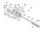
- FIG. 1A is a side view of an optical connector 100 (optical fiber connection unit) having a jacket gripping member 20 according to the first embodiment of the present invention.
- FIG. 1B is an exploded perspective view of the optical connector 100.
- the optical connector 100 includes a connector main body 10 (connection unit main body) and a retaining portion 40 that retains the end of the optical fiber cable 70 at the rear portion of the connector main body 10.
- the optical connector 100 is, for example, a field assembly type optical connector.
- the connector body 10 includes a body housing 11 and a ferrule 60 with a clamp portion housed in the body housing 11.
- the ferrule 60 with a clamp part includes a ferrule 61 in which an optical fiber 62 (built-in optical fiber 62) is inserted and fixed, and a clamp part 63 (optical fiber connector).
- the built-in optical fiber 62 protrudes rearward from the ferrule 61.
- An optical fiber 73 (inserted optical fiber) drawn from the end of the optical fiber cable 70 is inserted into the connector main body 10 and is butt-connected to the built-in optical fiber 62 in the clamp portion 63.
- Reference symbol P denotes a connection portion between the optical fiber 73 and the built-in optical fiber 62.
- the tip direction (left side in FIG. 1A) of the ferrule 61 of the ferrule 60 with a clamp portion may be referred to as the front, and the opposite direction may be referred to as the rear.
- the retaining portion 40 includes an outer gripping member 20 that grips and fixes the end of the optical fiber cable 70, and a retaining housing 41 that houses the outer gripping member 20.
- the retaining housing 41 includes a stop ring portion 42 inserted into the connector main body 10 and a rectangular tubular gripping member receiving portion 43 extending rearward from the stop ring portion 42.
- the holding member receiving portion 43 is provided between an elongated plate-like bottom plate portion 43a extending in the front-rear direction, a pair of side plate portions 43b and 43b erected on both side edges of the bottom plate portion 43a, and upper ends of the side plate portions 43b and 43b. It is a cylindrical shape with a rectangular cross section provided with the top plate portion 43c.
- the gripping member receiving portion 43 can store the jacket gripping member 20 in an internal space 44 surrounded by the bottom plate portion 43a, the pair of side plate portions 43b and 43b, and the top plate portion 43c.
- the gripping member receiving portion 43 can store and take out the outer gripping member 20 through the insertion opening 45 that is an opening at the rear end.
- rectangular openings 47 and 47 are formed in the pair of side plate portions 43b and 43b, respectively.
- Latches 48 and 48 extending rearward are formed on the front edges 47a and 47a of the openings 47 and 47, respectively.
- the latches 48, 48 are provided at the elongated plate-like latch bodies 49, 49 extending rearward from the front edges 47 a, 47 a of the openings 47, 47, and the leading ends of the latch bodies 49, 49 in the extending direction. It has the latching claw parts 50 and 50.
- the side plate portions 43b and 43b are arranged on the outer surface side of the side wall portions 22 and 23 of the jacket holding member 20 (outside in the arrangement direction of the side wall portions 22 and 23).
- the latch bodies 49, 49 can be elastically bent and deformed in the width direction of the gripping member receiving portion 43 (the arrangement direction of the pair of side plate portions 43b, 43b).
- the locking claws 50, 50 are formed to protrude inward from the inner surfaces 43b1, 43b1 of the side plate portions 43b, 43b.
- the locking claw portion 50 can be locked to one end edge 28 a of the locking recess 28 of the jacket gripping member 20.
- the locking claw portion 50 can restrict the rearward movement of the outer cover gripping member 20 accommodated in the gripping member receiving portion 43 by being locked to the one end edge 28 a of the locking recess 28.
- the front surface 50 a of the locking claw 50 is a surface facing forward, and is a locking surface that locks with the one end edge 28 a of the locking recess 28.
- the front surface 50 a of the locking claw 50 may be, for example, an inclined surface that increases the protruding height toward the front, or a surface that is perpendicular to the inner surface of the latch body 49.
- the rear surface 50b of the locking claw portion 50 may be, for example, an inclined surface that reduces the protruding height as it goes rearward.
- a tapered recess 43d that faces the internal space 44 and is recessed in a tapered shape from the rear to the front is formed.
- a rear end of the fiber introduction hole 42a for guiding the optical fiber 73 into the connector body 10 is opened at the front end of the tapered recess 43d.
- the tapered recess 43d guides the tip of the optical fiber 73 and facilitates insertion into the fiber introduction hole 42a.
- the end of the optical fiber cable 70 held by the jacket holding member 20 housed in the internal space 44 is pressed against the lower surface 43c1 (inner surface) of the rear portion of the top plate portion 43c.
- a pressing portion 46 is formed to protrude downward.
- the protruding height of the pressing portion 46 is such that, for example, a sufficient pressing force is applied to the upper surface of the optical fiber cable 70 in a state where the outer cover holding member 20 that holds the end of the optical fiber cable 70 is inserted into the inner space 44.
- the optical fiber cable 70 may be sandwiched between the bottom plate portion 43a so as to be firmly fixed.
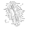
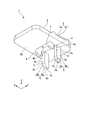
- FIG. 2A is a perspective view of the envelope gripping member 20.
- FIG. 2B is a view of the jacket gripping member 20 as viewed from one end (first cable groove 24A) of a groove portion 24 described later.
- FIG. 2C is a view of the jacket gripping member 20 as viewed from the other end (second cable groove 24B) of the groove portion 24 described later.
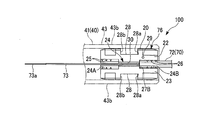
- FIG. 3A is a plan view showing an optical connector 100 in which a terminal of a first optical fiber cable 71 described later is fitted into the first cable groove 24A.
- FIG. 3B is a side sectional view of the optical connector 100 to which the first optical fiber cable 71 is attached.
- FIG. 4A is a plan sectional view of the optical connector 100 to which the first optical fiber cable 71 is attached.
- FIG. 4B is a rear view of the optical connector 100 to which the first optical fiber cable 71 is attached.
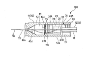
- FIG. 5A is a plan view showing the optical connector 100 in which a terminal of a second optical fiber cable 72 described later is fitted into the second cable groove 24B.
- FIG. 5B is a side sectional view of the optical connector 100 to which the second optical fiber cable 72 is attached.
- the XYZ coordinate system shown in FIGS. 2A to 2C may be referred to.
- the longitudinal direction of the groove portion 24 of the jacket gripping member 20 is defined as the X direction.
- the width direction of the groove portion 24 (the direction orthogonal to the X direction) is defined as the Y direction.
- a direction parallel to the depth direction of the groove 24 (a direction orthogonal to the X direction and the Y direction) is defined as a Z direction.
- the Z direction may also be referred to as the vertical direction.
- the side walls 22 and 23 protrude upward with respect to the bottom wall 21.
- the upper and lower directions referred to here do not limit the orientation when using the jacket gripping member 20.
- the jacket gripping member 20 includes a bottom wall portion 21 and a pair of side wall portions 22 and 23 that are erected on the bottom wall portion 21 with a space therebetween.
- the jacket holding member 20 is, for example, an integrally molded product made of plastic.
- the bottom wall portion 21 is formed in, for example, a rectangular plate shape in plan view.
- the side wall portions 22 and 23 are formed on the upper surface of the bottom wall portion 21 so as to protrude upward (Z direction) perpendicular to the bottom wall portion 21.
- the pair of side wall portions 22 and 23 are formed over the entire length of the bottom wall portion 21 along one and the other side edges of the bottom wall portion 21.
- a groove portion 24 is defined between the pair of side wall portions 22 and 23. Both ends in the longitudinal direction (X direction) of the groove portion 24 are opened (opened).
- the groove portion 24 is formed at one end portion in the longitudinal direction of the groove portion 24 to be fitted with the first optical fiber cable 71, and is formed at the other end portion in the longitudinal direction of the groove portion 24 and is formed at the second optical fiber cable.
- Second cable groove 24B into which 72 is fitted.
- the groove width W2 of the second cable groove 24B is smaller than the groove width W1 of the first cable groove 24A.
- the groove width centers of the first cable groove 24A and the second cable groove 24B coincide with each other.
- the first cable groove 24 ⁇ / b> A and the second cable groove 24 ⁇ / b> B can each have a length that is less than half the length of the bottom wall portion 21.
- the lengths of the first cable groove 24 ⁇ / b> A and the second cable groove 24 ⁇ / b> B shown in FIG. 2A and the like are, for example, about one third of the entire length of the jacket holding member 20. Therefore, the first cable groove 24A and the second cable groove 24B are not connected to each other, and are formed in the longitudinal direction of the bottom wall portion 21 via the central region 20A.
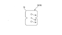
- an optical fiber 73 and a pair of strength members 74 and 74 are embedded in a jacket 75 having a rectangular cross section made of synthetic resin.
- the optical fiber cable 70 include an optical drop cable.
- the optical fiber 73 include an optical fiber and an optical fiber core.
- a coated optical fiber having a configuration in which a resin coating material 73b is attached to the outer periphery of the bare optical fiber 73a (see FIG. 1B) can be employed.
- the optical fiber cable 70 includes a first optical fiber cable 71 shown in FIG. 7A and a second optical fiber cable 72 shown in FIG. 7B.
- the second optical fiber cable 72 has a smaller cross-sectional size than the first optical fiber cable 71.
- the width of the second optical fiber cable 72 shown in this figure is smaller than the width of the first optical fiber cable 71 and the height is smaller than the height of the first optical fiber cable 71.
- the width is a dimension in the short side direction of the cross section, that is, the horizontal direction.
- the height is a dimension in the longitudinal direction of the cross section, that is, the vertical direction.
- the terminal of the optical fiber cable 70 (71, 72) and the jacket holding member 20 fixed to the terminal may be collectively referred to as a cable terminal 76 with a holding member.
- the first cable groove 24 ⁇ / b> A can fit the end of the first optical fiber cable 71 including the jacket 75.
- the first optical fiber cable 71 can be fitted into the first cable groove 24A in a posture in which the width direction of the first optical fiber cable 71 (the left-right direction in FIG. 7A) is directed in the groove width direction.
- the second cable groove 24 ⁇ / b> B can fit the end of the second optical fiber cable 72 including the jacket 75.
- the second optical fiber cable 72 can be fitted into the second cable groove 24B in a posture in which the width direction (left-right direction in FIG. 7B) is directed to the groove width direction.
- gripping claws 25 extending in the depth direction of the first cable groove 24A are respectively formed on the inner surfaces 22a and 23a of the side wall portions 22 and 23 forming a pair of inner surfaces of the first cable groove 24A. 25 (hereinafter also referred to as a first gripping claw 25) is projected.
- the first gripping claws 25 are, for example, protrusions having a substantially triangular cross section whose width gradually decreases in the protruding direction.
- a plurality of first gripping claws 25, 25 are arranged at intervals in the longitudinal direction of the first cable groove 24A (groove portion 24).
- the first gripping claws 25, 25 are arranged at positions facing each other through the first cable groove 24A.
- grip claws 26 and 26 (hereinafter referred to as second grips) extending in the depth direction of the second cable groove 24B, respectively.
- the claw 26 is also projected.
- the second gripping claw 26 is, for example, a protrusion having a substantially triangular cross section whose width gradually decreases in the protruding direction.
- a plurality of second gripping claws 26, 26 are arranged at intervals in the longitudinal direction of the second cable groove 24B (groove portion 24).
- the second gripping claws 26 and 26 are arranged at positions facing each other via the second cable groove 24B.
- the inner surfaces 22a and 23a facing each other through the first cable groove 24A are also referred to as first inner surfaces 22a and 23a
- the inner surfaces 22b and 23b facing each other through the second cable groove 24B are the second inner surfaces.
- side surfaces 22b and 23b are parallel to each other.
- the first inner surfaces 22a and 23a are parallel to each other.
- the second inner side surfaces 22b and 23b are parallel to each other and parallel to the first inner side surfaces 22a and 23a.
- the groove width centers of the first cable groove 24A and the second cable groove 24B coincide with each other. Specifically, the center between the first inner side surfaces 22a and 23a of the first cable groove 24A facing each other and the center between the second inner side surfaces 22b and 23b of the second cable groove 24B facing each other coincide with each other. Yes.
- the first gripping claw 25 includes a main portion 25a having a constant projecting dimension from the first inner side surfaces 22a and 23a, and a tapered upper end portion 25c formed at the upper end portion of the first cable groove 24A in the main portion 25a.
- the ridge lines 25b of the main portion 25a of the first gripping claws 25 facing each other in the groove width direction (Y direction) of the first cable groove 24A are parallel to each other.
- the tapered upper end portion 25c has a tapered shape that gradually reduces the protruding height toward the upper side (the opening side of the first cable groove 24A).
- the tapered upper end portion 25c facilitates the pushing of the first optical fiber cable 71 from above into the first cable groove 24A.
- the plane perpendicular to the groove width direction of the first cable groove 24A passing through the center between the ridge lines 25b of the main portion 25a of the first gripping claws 25 facing each other is referred to as a virtual vertical plane S1 (see FIG. 3A). Sometimes called.
- the second gripping claw 26 is formed at the upper end of the second cable groove 24B of the main portion 26a and the main portion 26a having a constant projecting dimension from the second inner side surfaces 22b and 23b. And a tapered upper end portion 26c.
- the projecting dimensions of the main portions 26a of the plurality of second gripping claws 26 are the same as each other.
- the ridge lines 26b of the main portion 26a of the second gripping claws 26 facing each other in the groove width direction of the second cable groove 24B are parallel to each other.
- the tapered upper end portion 26c has a tapered shape that gradually reduces the protruding height toward the upper side (the opening side of the second cable groove 24B).
- the tapered upper end portion 26c facilitates the pushing of the second optical fiber cable 72 from above into the second cable groove 24B.
- the center between the ridge lines 26b of the main portion 26a of the second gripping claws 26 facing each other in the groove width direction of the second cable groove 24B is located in the virtual vertical plane S1 (see FIG. 3A).
- the separation distance between the first inner side surfaces 22a, 23a of the first cable groove 24A (the groove width W1 of the first cable groove 24A) is set to be equal to or slightly larger than the width dimension of the first optical fiber cable 71.
- the separation distance between the ridge lines 25b of the first gripping claws 25 facing each other in the groove width direction of the first cable groove 24A is set slightly smaller than the width dimension of the first optical fiber cable 71.
- the first gripping claw 25 (specifically, the main portion 25a) bites into the outer jacket 75 of the first optical fiber cable 71 pushed into the first cable groove 24A.
- the first optical fiber cable 71 is fixed to the outer gripping member 20 by being gripped from both sides by the first gripping claws 25.
- the first gripping claws 25 ensure the cable holding force of the first optical fiber cable 71 against the outer gripping member 20, that is, the rear side of the first optical fiber cable 71 relative to the outer gripping member 20 (one end side of the groove 24). It contributes effectively to securing the resistance to movement.
- the separation distance between the second inner side surfaces 22b and 23b of the second cable groove 24B (the groove width W2 of the second cable groove 24B) is set to be equal to or slightly larger than the width dimension of the second optical fiber cable 72.
- the separation distance between the ridge lines 26b of the second gripping claws 26 facing each other in the groove width direction of the second cable groove 24B is set slightly smaller than the width dimension of the second optical fiber cable 72.
- the second gripping claw 26 (specifically, the main portion 26a) bites into the outer jacket 75 of the second optical fiber cable 72 pushed into the second cable groove 24B.
- the second optical fiber cable 72 is fixed to the jacket gripping member 20 by being gripped from both sides by the second gripping claws 26.
- the second gripping claw 26 ensures the cable holding force of the second optical fiber cable 72 against the jacket gripping member 20, that is, the rear portion of the second optical fiber cable 72 with respect to the jacket gripping member 20 (the other end of the groove 24). It contributes effectively to securing the resistance to movement.
- a position indication mark 29 can be formed at any position of the side wall portions 22 and 23.
- a position display mark 29 is formed in an area corresponding to the second cable groove 24B in the upper end surface of the side wall portion 22.
- the position display mark 29 may be, for example, a recess formed on the upper end surface of the side wall portion 22, or may be formed by printing or the like.
- the sheath gripping member 20 when attaching the jacket gripping member 20 to the end of the first optical fiber cable 71, the sheath gripping member 20 is in a posture with the first cable groove 24A facing rearward, so that the position display The mark 29 is located at the front portion of the outer cover holding member 20.
- the jacket holding member 20 when the jacket holding member 20 is attached to the end of the second optical fiber cable 72, the jacket holding member 20 has a posture in which the second cable groove 24 ⁇ / b> B is directed rearward. Therefore, the position display mark 29 is located at the rear portion of the outer cover gripping member 20.
- the position indication mark 29 allows the posture of the jacket gripping member 20 to be easily grasped visually, the optical fiber cable 70 (71, 72) of the jacket gripping member 20 due to the mistake of the cable grooves 24A, 24B. It is possible to prevent an error in the installation operation to the terminal.
- the inner surface 21a of the bottom wall portion 21 forming the groove portion 24 forms the first groove bottom surface 21b (bottom surface) forming the groove bottom of the first cable groove 24A and the groove bottom of the second cable groove 24B.
- the second groove bottom surface 21c of the second cable groove 24B is positioned higher than the first groove bottom surface 21b of the first cable groove 24A. That is, the second cable groove 24B is formed shallower than the first cable groove 24A.
- the second groove bottom surface 21c is formed in parallel with the first groove bottom surface 21b.
- the first groove bottom surface 21b may be perpendicular to the first inner side surfaces 22a and 23a.
- the second groove bottom surface 21c may be perpendicular to the second inner side surfaces 22b and 23b.
- the bottom wall portion 21 has a first bottom wall portion 21A constituting the first cable groove 24A and a second bottom wall portion 21B constituting the second cable groove 24B.
- the first bottom wall portion 21A is formed with a first recess 21d that is recessed from the first groove bottom surface 21b.
- the first recess 21 d is formed at a position including the center of the first cable groove 24 ⁇ / b> A in the groove width direction, and extends in the longitudinal direction of the groove 24.
- the first recess 21d is formed over substantially the entire length of the first cable groove 24A.
- the first recess 21d of the present embodiment penetrates in the thickness direction (Z direction) of the bottom wall portion 21 and opens to one end 21h of the bottom wall portion 21 corresponding to one end in the longitudinal direction of the groove portion 24. 21d.
- the first slit 21d is bent when the optical fiber 73 (inserted optical fiber) drawn from the end of the second optical fiber cable 72 fitted in the second cable groove 24B is bent and deformed. It is formed so that at least a part of part 77B can be accommodated.
- the inner surface of the first slit 21d (first recess 21d) is formed from the first groove bottom surface 21b of the first cable groove 24A toward the first slit 21d in the depth direction.
- the first inclined inner surface 21f is inclined inward in the width direction.
- the first inclined inner surface 21f smoothly guides the bending portion 77B (see FIG. 5B) of the optical fiber 73 into the first slit 21d.
- 21 f of 1st inclination inner surfaces should just be formed in the site
- a second recess 21e that is recessed from the second groove bottom surface 21c is formed in the second bottom wall portion 21B.
- the second recess 21 e is formed at a position including the center of the second cable groove 24 ⁇ / b> B in the groove width direction, and extends in the longitudinal direction of the groove 24.
- the second recess 21e is formed over substantially the entire length of the second cable groove 24B.
- the second recess 21e of the present embodiment penetrates in the thickness direction (Z direction) of the bottom wall portion 21 and opens to the other end 21i of the bottom wall portion 21 corresponding to the other end in the longitudinal direction of the groove portion 24. Two slits 21e. As shown in FIG.
- the second slit 21e is bent when the optical fiber 73 (inserted optical fiber) drawn from the end of the first optical fiber cable 71 fitted in the first cable groove 24A is bent and deformed. It is formed so that at least a part of the portion 77A can be accommodated.
- the inner surface of the second slit 21e extends from the second groove bottom surface 21c of the second cable groove 24B in the depth direction of the second slit 21e.
- the second inclined inner surface 21g is inclined inward in the width direction.
- the second inclined inner surface 21g smoothly guides the bending portion 77A (see FIG. 3B) of the optical fiber 73 into the second slit 21e.
- the second inclined inner surface 21g may be formed at least on the second groove bottom surface 21c side of the inner surface of the second slit 21e, but may be formed on the entire inner surface of the second slit 21e, for example.
- the optical fiber cables 71 and 72 can be easily fitted into the cable grooves 24A and 24B.
- the side wall portion 22 and the front side of the side wall portions 22 and 23 are separated from each other.
- 23 is elastically deformed, so that the first optical fiber cable 71 can be easily fitted into the first cable groove 24A.
- the entire side wall portions 22 and 23 are in the central region 20A. It is possible to deform such that it tilts around the fulcrum.
- the side wall portions 22 and 23 can tilt the side wall portions 22 and 23 so that the front end portions are separated from each other and the rear end portions are close to each other. Therefore, deformation such that the end portions of the side wall portions 22 and 23 are separated from each other is facilitated.
- the innermost surface 27A of the first cable groove 24A is a surface formed by a step between the first cable groove 24A and a fiber housing groove 30 (described later) that is narrower than the first cable groove 24A.
- the innermost surface 27A is a surface that abuts the end surface of the first optical fiber cable 71 fitted into the first cable groove 24A (particularly, the end surface of the jacket 75).
- the innermost surface 27 ⁇ / b> A can be used for positioning the first optical fiber cable 71 with respect to the outer covering member 20 in the longitudinal direction of the outer covering member 20.
- the innermost surface 27B of the second cable groove 24B is a surface formed by a step between the second cable groove 24B and a fiber housing groove 30 (described later) that is narrower than the second cable groove 24B.
- the innermost surface 27B is brought into contact with the end surface of the second optical fiber cable 72 fitted into the second cable groove 24B (particularly, the end surface of the outer jacket 75), whereby the second optical fiber in the longitudinal direction of the outer sheath holding member 20 is contacted. It can be used for positioning the cable 72 with respect to the outer gripping member 20.
- the groove portion 24 of the jacket gripping member 20 is a fiber accommodation groove in which the optical fiber 73 of the first optical fiber cable 71 or the second optical fiber cable 72 is accommodated between the first cable groove 24A and the second cable groove 24B. 30.
- the fiber accommodation groove 30 is formed to extend in the longitudinal direction of the bottom wall portion 21 and communicates the first cable groove 24A and the second cable groove 24B.
- the fiber accommodation groove 30 is formed narrower than the first cable groove 24A and the second cable groove 24B.
- the fiber accommodation groove 30 has an introduction part 30a opened upward and a main groove part 30b having a narrower width than the introduction part 30a.
- the main groove 30b is formed downward from the bottom of the introduction part 30a.
- the depth of the fiber accommodation groove 30 is such that the optical fiber 73 or the bare optical fiber 73a drawn out from the optical fiber cable 70 is accommodated with the optical fiber cable 70 (71, 72) fitted in at least the cable grooves 24A, 24B. It may be set as follows.
- the depth of the fiber accommodation groove 30 may be substantially the same as the depth of the first cable groove 24A as shown in FIG. 2B, for example, but is not limited thereto.
- locking recesses 28, 28 are formed at substantially the center in the longitudinal direction of the side wall portions 22, 23 among the outer surfaces of the side wall portions 22, 23 facing the outer side in the width direction of the jacket gripping member 20. ing.
- the locking recesses 28 are opened on the upper and lower surfaces of the side walls 22 and 23. That is, the locking recesses 28 and 28 are formed over the entire height direction of the side walls 22 and 23.
- the locking recess 28 is a recess having a certain depth that is recessed from the outer surface of the side walls 22, 23 to the inside in the width direction of the jacket gripping member 20, and locks the latch 48 of the retaining housing 41. Locks to the claw portion 50.
- One end edge 28a located on the second cable groove 24B side of the locking recess 28 is in a state in which the sheath holding member 20 attached to the first optical fiber cable 71 is accommodated in the retaining housing 41. It can be locked to the front surface 50 a of the locking claw portion 50.
- the one end edge 28a may be, for example, an inclined surface that is inclined forward as it goes in the depth direction of the locking recess 28, or a surface parallel to the depth direction of the locking recess 28 (perpendicular to the side bottom surface 28c). It may be a good surface).
- the jacket holding member 20 At the other end edge 28b located on the first cable groove 24A side of the locking recess 28, the jacket holding member 20 (see FIG.
- the other end edge 28b may be, for example, an inclined surface similar to the one end edge 28a or a surface parallel to the depth direction of the locking recess 28.
- a structure in which the locking claw portion 50 (locking portion) which is a convex portion formed in the gripping member receiving portion 43 is locked to the locking recess 28 of the jacket gripping member 20 is adopted.
- a structure in which the convex portion formed on the jacket gripping member 20 is engaged with the concave portion formed in the gripping member receiving portion 43 may be adopted.
- the jacket gripping member 20 can take two usage forms. As shown in FIGS. 3A and 3B, the first usage pattern is a mode in which the first optical fiber cable 71 is gripped and fixed by the jacket gripping member 20, and the second usage pattern is as shown in FIGS. 5A and 5B. As shown in FIG. 3, the second optical fiber cable 72 is held and fixed by the outer cover holding member 20.
- each usage pattern will be described.
- the optical connector 100 is attached to the end of the first optical fiber cable 71 (see FIG. 7A).
- an optical connector with a tool is prepared in which an insertion piece (not shown) is inserted between a pair of elements of a clamp portion 63 of a ferrule 60 with a clamp portion of the optical connector 100.
- the outer gripping member 20 is attached to the end of the first optical fiber cable 71 by fitting the end of the first optical fiber cable 71 into the first cable groove 24 ⁇ / b> A.
- the optical fiber 73 passes through the fiber housing groove 30 and extends further forward through the second cable groove 24B. Thereby, the cable terminal 76 with a holding member is obtained.
- the cable terminal 76 with the gripping member is inserted into the gripping member receiving portion 43 from the insertion port 45.
- the outer gripping member 20 abuts on the rear surface 50b (see FIG. 4A) of the latching claw portion 50 of the latch 48, and the latch 48 is pushed outward.
- FIG. 4A when the jacket gripping member 20 is further moved forward, the entire jacket gripping member 20 is accommodated in the gripping member receiving portion 43, and the locking claw portion 50 reaches the locking recess 28.
- the locking claw portion 50 is inserted into the locking recess 28 by the elastic repulsive force of the latch 48 and locked to the one end edge 28a.
- the position of the outer gripping member 20 is referred to as a storage position.
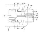
- the pair of side plate portions 43 b and 43 b are on the outer surface side of the pair of side wall portions 22 and 23, and restrict the outward displacement of the pair of side wall portions 22 and 23. For this reason, when the pulling direction force is applied to the optical fiber cable 70 (the first optical fiber cable 71), the side wall portions 22 and 23 contact the side plate portions 43b and 43b even if the side wall portions 22 and 23 are displaced in the widening direction. Touch. Thereby, the displacement of the side wall parts 22 and 23 in the widening direction as shown by a two-dot chain line in FIG. 2B can be prevented. Therefore, it is possible to suppress or prevent the optical fiber cable 70 from being pulled out from the outer gripping member 20.
- the optical fiber 73 protruding from the end of the optical fiber cable 70 is inserted into the clamp part 63 of the ferrule 60 with a clamp part from the fiber introduction hole 42a, and the bare optical fiber of the optical fiber 73 is inserted.
- 73 a is butt-connected to the built-in optical fiber 62.
- the optical fiber 73 is bent and deformed in the gripping member receiving portion 43.
- Reference numeral 77A denotes a bending portion.
- the bent portion 77A is introduced into the second slit 21e when the bent portion 77A is large. For this reason, the bending portion 77A does not contact the second bottom wall portion 21B, and the bending deformation of the optical fiber 73 is not restricted. Thus, adverse effects on the optical characteristics of the optical fiber 73 can be avoided.
- the insertion piece (not shown) is removed from the clamp portion 63.
- the pair of elements of the clamp part 63 are closed, and the built-in optical fiber 62 and the optical fiber 73 are gripped and fixed in a butt-connected state. Therefore, the butt connection state of the optical fiber 73 (bare optical fiber 73a) with respect to the built-in optical fiber 62 of the clamp part 63 can be kept stable.
- the attachment of the optical connector 100 to the terminal of the first optical fiber cable 71 is completed.
- the optical connector 100 is attached to the end of the second optical fiber cable 72 (see FIG. 7B).
- the outer gripping member 20 is attached to the end of the second optical fiber cable 72 by fitting the end of the second optical fiber cable 72 into the second cable groove 24B.
- a cable terminal 76 is obtained.
- the outer gripping member 20 When the cable terminal 76 with the gripping member is inserted into the gripping member receiving portion 43 from the insertion opening 45, the outer gripping member 20 is housed in the gripping member receiving portion 43, as in the case of the first use state.
- the locking claw 50 is locked to the other end edge 28 b of the locking recess 28.
- the outer gripping member 20 is fixed to the gripping member receiving portion 43.
- the bare optical fiber 73 a of the optical fiber 73 is butt-connected to the built-in optical fiber 62 at the clamp portion 63.
- the optical fiber 73 is bent and deformed in the gripping member receiving portion 43.
- Reference numeral 77B denotes a bending portion. Since the first slit 21d is formed in the first bottom wall portion 21A, the bent portion 77B is introduced into the first slit 21d when the bent portion 77B is large. Therefore, the bending portion 77B does not contact the first bottom wall portion 21A, and the bending deformation of the optical fiber 73 is not restricted. Thus, adverse effects on the optical characteristics of the optical fiber 73 can be avoided.
- the pair of elements of the clamp part 63 is closed, and the built-in optical fiber 62 and the optical fiber 73 are held and connected to each other and fixed (see FIG. (See FIG. 1A).
- the attachment of the optical connector 100 to the terminal of the second optical fiber cable 72 is completed.
- the jacket gripping member 20 is formed at one end portion of the groove portion 24 and is formed at the other end portion of the first cable groove 24A into which the first optical fiber cable 71 is fitted and the second end portion of the groove portion 24. And a second cable groove 24B into which the optical fiber cable 72 is fitted. Therefore, it is possible to design the width dimensions and the like according to the first and second optical fiber cables 71 and 72 in the cable grooves 24A and 24B, respectively. Therefore, a high cable retaining force can be easily secured for each of the first and second optical fiber cables 71 and 72. Since the jacket gripping member 20 can handle two types of optical fiber cables 71 and 72, the cost can be reduced compared to the case where a dedicated jacket gripping member is prepared for each cable cross-sectional size.
- the first cable groove 24A and the second cable groove 24B are formed at different ends of the groove part 24, the positions where the various types of optical fiber cables 71 and 72 are fitted into the cable grooves 24A and 24B can be easily provided. I can grasp. Therefore, it is possible to suppress the situation where the optical fiber cables 71 and 72 are fixed to the wrong cable groove.
- the jacket holding member 20 is applied to the optical connector 100, but the application destination of the jacket holding member of the present invention is not limited to the optical connector.
- an optical fiber connector such as a mechanical splice may be used instead of the clamp part 63 shown in FIG. 1A.
- the optical fiber connection unit 110 shown in FIG. 8 includes a connection unit main body 80 having a mechanical splice 83 (optical fiber connector) and a retaining portion 40.
- the mechanical splice 83 can butt-connect the optical fiber 82 inserted from one end and the optical fiber 73 inserted from the other end.
- FIG. 6 is a view showing a jacket gripping member 120 which is an example in which the slits 21d and 21e are not formed.
- the envelope gripping member 120 is different from the envelope gripping member 20 shown in FIG. 2A and the like in that the slits 21d and 21e are not formed in the bottom wall portion 21.
- the first cable groove 24A and the second cable groove 24B each have a constant width along the longitudinal direction of the groove portion 24.
- An optical fiber cable having a relatively large width can be fitted into the first groove region, and an optical fiber cable having a relatively small width can be fitted into the second groove region. Since one or both of the first cable groove and the second cable groove have the two groove regions, the types of cables that can be gripped by the same anchoring fixing member can be further increased.
- the number of groove regions formed in one cable groove may be three or more.
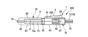
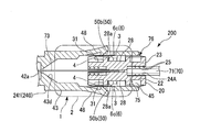
- FIG. 9A is a side view of the removal tool 1 according to the second embodiment of the present invention and an optical connector 200 to which the removal tool 1 can be applied.
- FIG. 9B is an exploded perspective view of the removal tool 1 and the optical connector 200.
- the optical connector 200 optical fiber connection unit
- the optical connector 200 includes a connector main body 10 (connection unit main body) and a retaining portion 240 that retains the end of the optical fiber cable 70 at the rear of the connector main body 10. I have.
- the optical connector 200 is, for example, a field assembly type optical connector.
- the connector body 10 includes a body housing 11 and a ferrule 60 with a clamp portion housed in the body housing 11.
- the ferrule 60 with a clamp part includes a ferrule 61 in which an optical fiber 62 (built-in optical fiber 62) is inserted and fixed, and a clamp part 63 (optical fiber connector).
- the built-in optical fiber 62 protrudes rearward from the ferrule 61.
- the clamp part 63 can be held and fixed in a state where the built-in optical fiber 62 and the optical fiber 73 are butt-connected by a pair of elements.
- An optical fiber 73 (inserted optical fiber) drawn from the end of the optical fiber cable 70 is inserted into the connector main body 10 and is butt-connected to the built-in optical fiber 62 in the clamp portion 63.
- Reference symbol P denotes a connection portion between the optical fiber 73 and the built-in optical fiber 62.
- the tip direction (left side in FIG. 9A) of the ferrule 61 of the ferrule 60 with a clamp part may be referred to as the front, and the opposite direction may be referred to as the rear.
- the retaining portion 240 includes an outer gripping member 20 that grips and fixes the end of the optical fiber cable 70, and a retaining housing 241 that houses the outer gripping member 20.
- the retaining housing 241 includes a stop ring portion 42 inserted into the connector main body 10 and a rectangular tube-shaped gripping member receiving portion 43 extending rearward from the stop ring portion 42.
- the holding member receiving portion 43 is provided between an elongated plate-like bottom plate portion 43a extending in the front-rear direction, a pair of side plate portions 43b and 43b erected on both side edges of the bottom plate portion 43a, and upper ends of the side plate portions 43b and 43b. It is a cylindrical shape with a rectangular cross section provided with the top plate portion 43c.
- the gripping member receiving portion 43 can store the jacket gripping member 20 in an internal space 44 surrounded by the bottom plate portion 43a, the pair of side plate portions 43b and 43b, and the top plate portion 43c.
- the gripping member receiving portion 43 can store and take out the outer gripping member 20 through the insertion opening 45 that is an opening at the rear end.
- rectangular openings 47 and 47 are formed in the pair of side plate portions 43b and 43b, respectively.
- Latches 48 and 48 extending rearward are formed on the front edges 47a and 47a of the openings 47 and 47, respectively.
- the latches 48, 48 are provided at the elongated plate-like latch bodies 49, 49 extending rearward from the front edges 47 a, 47 a of the openings 47, 47, and the leading ends of the latch bodies 49, 49 in the extending direction. It has the latching claw parts 50 and 50.
- the side plate portions 43b and 43b are arranged on the outer surface side of the side wall portions 22 and 23 of the jacket gripping member 20 described later (outside in the arrangement direction of the side wall portions 22 and 23).
- the latch bodies 49, 49 can be elastically bent and deformed in the width direction of the gripping member receiving portion 43 (the arrangement direction of the pair of side plate portions 43b, 43b).
- the locking claws 50 and 50 (locking portions) are formed so as to protrude inward from the inner surfaces of the side plate portions 43b and 43b.
- the locking claw portion 50 can be engaged with one end edge 28 a (or the other end edge 28 b) of the locking recess 28 (locking receiving portion) of the jacket gripping member 20.
- the locking claw portion 50 can restrict the rearward movement of the outer gripping member 20 accommodated in the gripping member receiving portion 43 by engaging with the one end edge 28 a (or the other end edge 28 b) of the locking recess 28. it can.
- the front surface 50 a of the locking claw 50 is a surface facing forward, and is an engagement surface that engages with one end edge 28 a of the locking recess 28.
- the front surface 50 a of the locking claw 50 may be, for example, an inclined surface that increases in protruding height toward the front, or a surface that is perpendicular to the inner surface of the latch body 49.
- the rear surface 50b of the locking claw portion 50 may be, for example, an inclined surface that decreases the protruding height toward the rear.
- the upper surface 43c1 (outer surface) of the top plate portion 43c is a flat surface.
- a pair of insertion slits 51, 51 are formed in the top plate portion 43c with an interval in the width direction (Y direction).
- the insertion slits 51 and 51 are openings for inserting the release operation portions 3 and 3 and the engagement convex portions 4 and 4 of the removal tool 1 to be described later, and in the length direction (X direction) of the top plate portion 43c. It is formed to extend.
- the insertion slits 51 and 51 are formed at positions on one side and the other side of the center in the width direction (Y direction), respectively, and at least a part of the insertion slits 51 and 51 is formed in the vertical direction ( Z direction).
- the top plate portion 43c is formed with a confirmation slit 52 at the center position in the width direction (Y direction) where the optical fiber 73 in the gripping member receiving portion 43 can be seen.
- the confirmation slit 52 is formed to extend in the length direction (X direction) of the top plate portion 43c. Through the confirmation slit 52, it is possible to confirm the bending generated in the optical fiber 73.
- a tapered recess 43d is formed in the front portion of the gripping member receiving portion 43 so as to face the internal space 44 and is recessed in a tapered shape from the rear end toward the front side.
- a rear end of the fiber introduction hole 42a for guiding the optical fiber 73 into the connector body 10 is opened at the front end of the tapered recess 43d.
- the tapered recess 43d guides the tip of the optical fiber 73 and facilitates insertion into the fiber introduction hole 42a.
- a pressing portion 46 that presses the end of the optical fiber cable 70 held by the jacket holding member 20 housed in the internal space 44. It is formed to protrude downward.
- the jacket gripping member 20 has a configuration common to the first embodiment.
- the jacket gripping member 20 will be further described.
- the first cable groove 24A is formed to reach one end 21h (the end on the near side in FIG. 11) in the longitudinal direction of the bottom wall portion 21, and is opened (opened) at one end 21h.
- the first cable groove 24 ⁇ / b> A is formed to extend in the longitudinal direction (X direction) of the bottom wall portion 21.
- the second cable groove 24B is formed so as to reach the other end 21i in the longitudinal direction of the bottom wall portion 21 (end on the back side in FIG. 11), and is opened (opened) at the other end 21i.
- the second cable groove 24 ⁇ / b> B extends in the longitudinal direction of the bottom wall portion 21.
- the cross-sectional size of the second cable groove 24B orthogonal to the longitudinal direction of the groove portion 24 is smaller than the cross-sectional size of the first cable groove 24A. Therefore, the end of the first optical fiber cable 71 can be fitted into the first cable groove 24A. The end of the second optical fiber cable 72 can be fitted into the second cable groove 24B.
- the terminal of the optical fiber cable 70 (71, 72) and the jacket holding member 20 fixed to the terminal may be collectively referred to as a cable terminal 76 with a holding member.
- the dimension in the X direction of the locking recess 28 is desirably larger than the dimension in the same direction of the release operation part 3 (see FIGS. 12 and 13B) of the removal tool 1 described later.
- the release operation portion 3 inserted in the rear portion of the locking recess 28 moves forward relative to the outer gripping member 20, so that the rear surface 50 b of the locking claw portion 50 is moved forward by the front edge of the release operation portion 3. It can also be displaced outwardly by pressing.
- a structure in which a locking claw portion 50 (locking portion) which is a convex portion formed in the gripping member receiving portion 43 is locked to a locking recess portion 28 (locking receiving portion) of the outer gripping member 20 is adopted. Also good.
- first engaging recesses 31 and 31 are formed at positions on one side in the longitudinal direction (X direction) with respect to the locking recesses 28 and 28, respectively.
- the first engagement recesses 31, 31 are recesses having a constant depth formed at positions including the upper edges of the side wall portions 22, 23, and are in the posture shown in FIG. 12 (the first cable groove 24A is directed rearward). In the posture), the first engaging recesses 31 are formed in front portions of the side walls 22 and 23. For this reason, the first engaging recesses 31, 31 are positioned in front of the locking recesses 28, 28 and spaced from the locking recesses 28, 28.
- first engaging recesses 31 and 31 are formed at the upper portions of the side wall portions 22 and 23, the lower portion of the latch 48 is at a lower position than the first engaging recess 31. 50 cannot enter the engaging recess 31.
- An edge 31a located at the rear end of the first engagement recess 31 can be engaged with a rear edge 4a of an engagement convex portion 4 of the removal tool 1 described later.
- the edge 31a can be a surface perpendicular to the side bottom surface 31b of the first engagement recess 31, for example.
- second engaging recesses 32, 32 are formed at positions on the other side in the longitudinal direction with respect to the locking recesses 28, 28.
- the second engagement recesses 32, 32 are recesses having a constant depth formed at positions including the upper edges of the side wall portions 22, 23, and are in the posture shown in FIG. 12 (the first cable groove 24A is directed rearward). In the posture), the second engaging recesses 32 and 32 are formed in the rear portions of the side wall portions 22 and 23. For this reason, the second engaging recesses 32, 32 are located behind the locking recesses 28, 28 and spaced from the locking recesses 28, 28. Similar to the first engagement recesses 31, 31, the second engagement recesses 32, 32 are formed at a height position where the latching claw portion 50 of the latch 48 cannot enter.
- the end edge 32a located at the front end of the second engagement recess 32 is the rear edge 4a of the engagement protrusion 4 of the removal tool 1. Can be engaged.
- the end edge 32a can be a surface perpendicular to the side bottom surface 32b of the second engagement recess 32, for example.
- an optical connector with an insertion tool is prepared in which an insertion piece (not shown) is inserted between a pair of elements of the clamp portion 63 of the ferrule 60 with a clamp portion of the optical connector 200.
- the outer gripping member 20 is attached to the end of the first optical fiber cable 71 by fitting the end of the first optical fiber cable 71 into the first cable groove 24 ⁇ / b> A.
- the optical fiber 73 passes through the fiber housing groove 30 and extends further forward through the second cable groove 24B. Thereby, the cable terminal 76 with a holding member is obtained.
- the cable terminal 76 with the gripping member is inserted into the gripping member receiving portion 43 from the insertion port 45.
- the envelope gripping member 20 abuts on the rear surface 50b (see FIG. 13A) of the latching claw portion 50 of the latch 48, and the latch 48 is pushed outward.
- FIG. 13A when the jacket gripping member 20 is further moved forward, the entire jacket gripping member 20 is accommodated in the gripping member receiving portion 43, and the locking claw portion 50 reaches the locking recess 28.
- the locking claw portion 50 is inserted into the locking recess 28 by the elastic repulsive force of the latch 48 and locked to the one end edge 28a.
- the outer gripping member 20 is fixed to the gripping member receiving portion 43.
- the position of the outer gripping member 20 is referred to as a storage position.
- the optical fiber 73 protruding from the end of the optical fiber cable 70 is inserted into the clamp part 63 of the ferrule 60 with a clamp part from the fiber introduction hole 42a, and the bare optical fiber of the optical fiber 73 is inserted.
- 73 a is butt-connected to the built-in optical fiber 62.
- the optical fiber 73 is bent and deformed in the gripping member receiving portion 43. As a result, a sufficient butting force is applied to the optical fiber 73.
- the insertion piece (not shown) is removed from the clamp portion 63.
- the pair of elements of the clamp part 63 are closed, and the built-in optical fiber 62 and the optical fiber 73 are gripped and fixed in a butt-connected state. Therefore, the butt connection state of the optical fiber 73 (bare optical fiber 73a) with respect to the built-in optical fiber 62 of the clamp part 63 can be kept stable.
- the attachment of the optical connector 200 to the terminal of the first optical fiber cable 71 is completed.
- the optical connector 200 When the optical connector 200 is attached to the end of the second optical fiber cable 72, the end of the second optical fiber cable 72 is fitted into the second cable groove 24B instead of the first optical fiber cable 71, thereby The holding member 20 is attached to the end of the second optical fiber cable 72.
- Other procedures are the same as those for attaching the optical connector 200 to the terminal of the first optical fiber cable 71.
- FIG. 10 is a perspective view of the removal tool 1.
- FIG. 12 is a side view of the removal tool 1 and the outer gripping member 20.
- the XYZ coordinate system shown in FIG. 10 may be referred to.
- the direction in which the pair of release operation units 3 and 3 are arranged in a plane orthogonal to the thickness direction of the plate-like base unit 2 is defined as a Y direction.
- the direction perpendicular to the thickness direction of the base body 2 and the Y direction is taken as the X direction.
- a direction orthogonal to the X direction and the Y direction is defined as a Z direction.
- the Z direction is also referred to as the vertical direction.
- the release operation portions 3 and 3 protrude downward with respect to the base body portion 2.
- the upper and lower sides do not limit the orientation when the removal tool 1 is used.
- the removal tool 1 includes a base portion 2, a pair of release operation portions 3 and 3 extending from the lower surface 2 a of the base portion 2, and a pair protruding from the lower surface 2 a of the base portion 2.
- the base portion 2 is, for example, a plate having a substantially rectangular shape in plan view.
- the base portion 2 shown in FIG. 10 is rectangular in plan view.
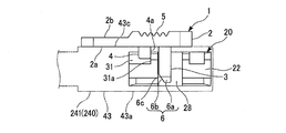
- An anti-slip uneven portion 5 is formed on the upper surface 2 b (outer surface) of the base portion 2.
- the anti-slip uneven portion 5 has a plurality of grooves 5 a and a plurality of protrusions 5 b extending in the width direction (Y direction) in a partial region including the center in the length direction (X direction) of the base portion 2. .
- the non-slip uneven portion 5 increases the frictional resistance of the upper surface 2b of the base portion 2 against the operator's fingers and the like when the removal tool 1 and the outer gripping member 20 are slid in the X direction. it can.
- a confirmation window 7 through which the optical fiber 73 in the gripping member receiving portion 43 can be visually observed is formed in the approximate center of the base portion 2. With the confirmation window 7, it is possible to confirm the bending that has occurred in the optical fiber 73.
- the release operation portions 3 and 3 are formed to extend downward (Z direction) perpendicular to the lower surface 2 a of the base portion 2.
- the release operation units 3 and 3 are formed in a columnar shape having a substantially rectangular cross section.
- the two release operation parts 3 and 3 are arranged at intervals in the Y direction.
- Press surfaces 6 and 6 that are inclined with respect to the extending direction of the release operation units 3 and 3 are formed at the distal ends of the release operation units 3 and 3.
- the pressing surface 6 includes an outer inclined surface 6 a formed from the front end surface 3 a of the release operation unit 3 to the outer side surface 3 b of the release operation unit 3 facing outward in the width direction of the base unit 2, and the front end surface 3 a of the release operation unit 3.
- a front inclined surface 6b formed from the front surface 3c to the front surface 3c.
- the front inclined surface 6b is an adjacent inclined surface adjacent to the outer inclined surface 6a.
- the outer inclined surface 6a is inclined closer to the inner side (direction approaching the center in the width direction of the base body 2) toward the distal end portion in the extending direction of the release operation unit 3.
- the front inclined surface 6b is inclined closer to the rear side toward the distal end side in the extending direction of the release operation unit 3. Therefore, the pressing edge portion 6c (pressing portion) that is the boundary between the outer inclined surface 6a and the front inclined surface 6b is inclined toward the rear and inward toward the distal end portion in the extending direction of the release operation portion 3. ing.
- the pressing edge portion 6c is formed so that the latching claw portion 50 of the latch 48 moves outward (in the width direction outward direction of the retention housing 241) as the release operation portion 3 is inserted into the retention housing 241.
- the locking claw portion 50 is pressed so as to be displaced in the direction (see FIG. 13 and FIG. 14).
- the engaging protrusions 4 and 4 are formed to protrude downward (Z direction) perpendicular to the lower surface 2 a of the base body 2.
- the engaging convex parts 4 and 4 are formed in a substantially rectangular cross section.
- the two engagement convex parts 4 and 4 are arranged at intervals in the Y direction.
- the engagement convex portions 4 and 4 are positioned in front of the release operation portions 3 and 3.
- the engagement convex portion 4 can be engaged with the first engagement concave portion 31 of the outer cover gripping member 20, and the outer gripping member 20 can be pressed rearward by engaging with the first engagement concave portion 31. (See FIGS. 14 and 15).
- the protruding dimension (from the lower surface 2a of the base body 2) of the engaging convex part 4 is smaller than the extending dimension (from the lower surface 2a) of the release operation part 3. Accordingly, the engagement convex portion 4 and the release operation portion 3 can be easily identified by visual observation, so that the operator can easily grasp the posture of the removal tool 1 with respect to the outer gripping member 20 and the retaining housing 241. Therefore, it is possible to prevent an erroneous operation due to a mistake in the front and rear of the removal tool 1.
- FIG. 9B the removal tool 1 is lowered toward the retaining housing 241.
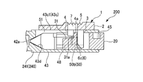
- the release operation portion 3 is inserted into the gripping member receiving portion 43 through the insertion slit 51 and abuts on the locking claw portion 50 of the latch 48.
- the pressing edge 6c of the pressing surface 6 of the release operation unit 3 contacts the upper edge 50b1 of the rear surface 50b of the locking claw 50.
- the release operation unit 3 is shown in a cross section at a height position where it comes into contact with the locking claw unit 50.
- the pressing edge 6 c is inclined toward the rear and inward toward the distal end side in the extending direction of the release operation portion 3, and as shown in the enlarged view of FIG. 13A.
- the abutment portion 50 abuts against the rear surface 50b of the locking claw portion 50 at a position relatively rearward and inward.
- the rear surface 50b of the locking claw portion 50 with which the pressing edge portion 6c abuts is an inclined surface that is closer to the outer side toward the rear, the obliquely forward force received from the pressing edge portion 6c efficiently acts on the rear surface 50b. . Due to the outward displacement of the locking claw 50, the locking claw 50 is unlocked from the one end edge 28a of the locking recess 28.
- the engaging convex portion 4 is inserted into the first engaging concave portion 31, and can be engaged with the end edge 31a.
- a finger or the like is applied to the upper surface 2 b of the base portion 2 to press the base portion 2 backward.
- the place to which a finger or the like is applied is the non-slip uneven portion 5, the backward pressing force against the base portion 2 can be increased, and the reliability of the detachment operation of the outer gripping member 20 can be increased.
- the engaging convex portion 4 engages with the end edge 31a of the first engaging concave portion 31, and the engaging convex portion 4 causes the first engaging concave portion 31 (outer gripping member) to be engaged. 20) A backward force is applied to the edge 31a.
- the removal tool 1 moves rearward.
- the removal tool 1 may slide on the upper surface 43c1 in a state where the lower surface 2a of the base portion 2 is in contact with the upper surface 43c1 of the top plate portion 43c of the retaining housing 241.
- the jacket gripping member 20 moves backward (in the removal direction). Accordingly, the outer gripping member 20 can be taken out from the gripping member receiving portion 43 through the insertion port 45.
- the release operation unit 3 As described above, according to the above-described removal tool 1, it is only necessary to insert the release operation unit 3 into the retaining housing 241 and insert it between the outer gripping member 20 and the latch 48. Since the latching claw 50 of the latch 48 is released from the latching recess 28, the outer gripping member 20 can be removed from the retaining housing 241. Therefore, when removing the jacket gripping member 20, it is only necessary to secure one working space on the outside (upper side) of the retaining housing 241. That is, the work space for removing the jacket gripping member 20 can be reduced in a compact manner. Therefore, it is possible to reduce the difficulty in removing the outer cover gripping member 20.
- the pressing edge 6 c formed at the distal end of the release operation part 3 presses the latch outward to release the latch. Displace outward. Therefore, the locking claw portion 50 of the latch 48 can be easily released from the locking recess 28 of the outer gripping member 20.
- the pressing edge 6 c is formed so as to be inclined with respect to the extending direction of the release operation unit 3, and the pressing edge 6 c presses the latch 48 according to the inclination and displaces outward. Therefore, the displacement of the latch 48 can be performed smoothly.
- the removal tool 1 Since the removal tool 1 has the engagement convex portion 4, the outer gripping member 20 is removed by the engagement convex portion 4 in the removal direction (rearward) while being held in a state in which the latch 48 is unlocked by the release operation portion 3. ). Therefore, the removal of the outer gripping member 20 from the retention housing 241 can be easily realized by a series of operations in which the removal tool 1 is inserted into the retention housing 241 and moved backward.
- the jacket gripping member 20 and the optical connector 200 constitute an optical connector kit (optical fiber connection unit kit).
- the technical scope of the present invention is not limited to the above embodiment, and various modifications can be made without departing from the spirit of the present invention.
- the jacket gripping member 20 shown in FIG. 9 and the like has a first cable groove 24A formed at one end of the groove 24 and a second cable groove 24B formed at the other end.
- the configuration may be such that there is no cable groove at one end of the cable groove.
- the second cable groove is not provided at the other end of the groove portion 24 (the left portion in FIG. 16).
- a space 33 between the side wall portions 22 and 23 at the other end of the groove portion 24 is an optical fiber wiring space through which the inserted optical fiber drawn from the end of the optical fiber cable held by the first cable groove 24A passes.
- the removal tool 1 is applied to the optical connector 200, but the application destination of the removal tool of the present invention is not limited to the optical connector.
- an optical fiber connector such as a mechanical splice may be used instead of the clamp part 63 shown in FIG. 9A.
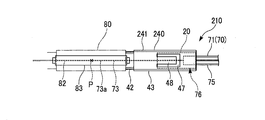
- An optical fiber connection unit 210 shown in FIG. 17 includes a connection unit main body 80 having a mechanical splice 83 (optical fiber connector) and a retaining portion 240.
- the mechanical splice 83 can butt-connect the optical fiber 82 inserted from one end and the optical fiber 73 inserted from the other end.
- the insertion direction of the release operation unit 3 with respect to the retaining housing 241 is downward (a direction perpendicular to the extending direction of the latch 48).
- the inserting direction is not limited to this, for example, the extension of the latch 48 is extended.
- the direction may intersect with the outgoing direction.
- SYMBOLS 10 Connector main body (connection unit main body) 20, 120 ... Outer gripping member (cable outer cover gripping member), 21 ... Bottom wall portion, 21d ... First slit (first concave portion), 21b ... First groove bottom surface ( Bottom surface), 21e ... second slit (second recess), 21c ... second groove bottom surface (bottom surface), 21f ... first inclined inner surface, 21g ... second inclined inner surface, 21A ... first bottom wall portion, 21h ... bottom wall 21i ... the other end of the bottom wall, 21B ... the second bottom wall, 22, 23 ... the side wall, 24 ... the groove, 24A ... the first cable groove, 24B ... the second cable groove, 25 ... first.
- Gripping claw, 26 ... second holding claw, 30 ... fiber receiving groove, 40,240 ... clamping part, 41,241 ... rescue housing, 43b, 43b ... side plate part, 61 ... ferrule, 62 ... built-in optical fiber, 63 ... Clamp part (optical fiber connector), 70 ... light Fiber cable, 71 ... first optical fiber cable, 72 ... second optical fiber cable, 73 ... optical fiber (insertion optical fiber), 80 ... connection unit body, 82 ... optical fiber, 83 ... mechanical splice (optical fiber connector) , 100, 200 ... optical connectors (optical fiber connection units), 110, 210 ... optical fiber connection units.
Landscapes
- Physics & Mathematics (AREA)
- General Physics & Mathematics (AREA)
- Optics & Photonics (AREA)
- Mechanical Coupling Of Light Guides (AREA)
Abstract
底壁部と、前記底壁部上に互いに間隔をあけて立設された一対の側壁部とを有し、前記一対の側壁部の間の溝部は、前記溝部の一端部に形成されて第1光ファイバケーブルを嵌め込む第1ケーブル溝と、前記溝部の他端部に形成されて前記第1光ファイバケーブルに比べて断面サイズが小さい第2光ファイバケーブルを嵌め込む第2ケーブル溝と、を有し、前記第2ケーブル溝の幅が、前記第1ケーブル溝よりも小さいケーブル外被把持部材を提供する。
Description
本発明は、光ファイバケーブルの引き留めに利用可能なケーブル外被把持部材及びこれを含む光ファイバ接続ユニットに関する。
本願は、2015年4月14日に出願された日本国特許出願2015-082347号および2015-082348号に基づき優先権を主張し、その内容をここに援用する。
本願は、2015年4月14日に出願された日本国特許出願2015-082347号および2015-082348号に基づき優先権を主張し、その内容をここに援用する。
光ファイバケーブルとしては、光ファイバと一対の抗張力体とが合成樹脂製の断面矩形の外被に埋め込まれた構造のファイバ埋め込み形ケーブル(例えば光ドロップケーブルなど)がある。
ファイバ埋め込み形ケーブルには、このケーブルの端末に固定した外被把持部材(引留用固定部材)を引き留める構造を有する光ファイバ接続ユニット(光コネクタ)が用いられる(例えば、特許文献1を参照)。
ファイバ埋め込み形ケーブルには、このケーブルの端末に固定した外被把持部材(引留用固定部材)を引き留める構造を有する光ファイバ接続ユニット(光コネクタ)が用いられる(例えば、特許文献1を参照)。
ところで、ファイバ埋め込み形ケーブルには、断面サイズが異なる複数の種類がある。複数種類のファイバ埋め込み形ケーブルに外被把持部材を用いる場合は、適切なケーブル引き留め力を確保する観点で、ケーブル断面サイズ毎に専用の外被把持部材を用意することが多い。
しかしながら、ケーブル断面サイズ毎に専用の外被把持部材を用意することは、管理の手間の増大およびコスト高の原因となる。
本発明は、上記事情に鑑みてなされたもので、互いに断面サイズが異なる複数種類の光ファイバケーブルのそれぞれについて高い引き留め力を容易に確保でき、かつコスト抑制が可能なケーブル外被把持部材及び光ファイバ接続ユニットを提供する。
本発明は、上記事情に鑑みてなされたもので、互いに断面サイズが異なる複数種類の光ファイバケーブルのそれぞれについて高い引き留め力を容易に確保でき、かつコスト抑制が可能なケーブル外被把持部材及び光ファイバ接続ユニットを提供する。
本発明の第1態様は、ケーブル外被把持部材であって、底壁部と、前記底壁部上に互いに間隔をあけて立設された一対の側壁部とを有し、前記一対の側壁部の間の溝部は、その一端部に形成されて第1光ファイバケーブルを嵌め込む第1ケーブル溝と、前記溝部の他端部に形成されて前記第1光ファイバケーブルに比べて断面サイズが小さい第2光ファイバケーブルを嵌め込む第2ケーブル溝と、を有し、前記第2ケーブル溝の幅が、前記第1ケーブル溝よりも小さい。
本発明の第2態様では、上記第1態様のケーブル外被把持部材において、前記底壁部には、前記第1ケーブル溝の底面から窪む第1凹部と、前記第2ケーブル溝の底面から窪む第2凹部とが形成されていてもよい。
本発明の第3態様では、上記第2態様のケーブル外被把持部材において、前記第1凹部及び前記第2凹部の内面が、前記第1ケーブル溝及び第2ケーブル溝の底面から前記第1凹部及び前記第2凹部の深さ方向に向かうにしたがって、前記第1凹部及び前記第2凹部の幅方向内側に傾斜する傾斜内面を有していてもよい。
本発明の第2態様では、上記第1態様のケーブル外被把持部材において、前記底壁部には、前記第1ケーブル溝の底面から窪む第1凹部と、前記第2ケーブル溝の底面から窪む第2凹部とが形成されていてもよい。
本発明の第3態様では、上記第2態様のケーブル外被把持部材において、前記第1凹部及び前記第2凹部の内面が、前記第1ケーブル溝及び第2ケーブル溝の底面から前記第1凹部及び前記第2凹部の深さ方向に向かうにしたがって、前記第1凹部及び前記第2凹部の幅方向内側に傾斜する傾斜内面を有していてもよい。
本発明の第4態様は、光ファイバ接続ユニットであって、光ファイバ接続器を有する接続ユニット本体と、光ファイバケーブルの端末を引き留める引き留め部とを備え、前記光ファイバ接続器は、前記光ファイバ接続器に一方の側から挿入された光ファイバと、前記光ファイバケーブルの端末から引き出されて前記光ファイバ接続器の他方の側から挿入された挿入光ファイバとを突き合わせ接続させ、前記引き留め部は、上記第1から第3態様のいずれか一態様のケーブル外被把持部材と、前記ケーブル外被把持部材を収納する引留用ハウジングとを有する。
本発明の第5態様では、上記第4態様の光ファイバ接続ユニットにおいて、前記接続ユニット本体がフェルールを有し、前記光ファイバが前記フェルールに内挿固定された内蔵光ファイバであってもよい。
本発明の第6態様では、上記第4又は第5態様の光ファイバ接続ユニットにおいて、前記引留用ハウジングは、これに収納された前記ケーブル外被把持部材の前記一対の側壁部の配列方向外側に配されて前記一対の側壁部の外方変位を規制する一対の側板部を有していてもよい。
本発明の第5態様では、上記第4態様の光ファイバ接続ユニットにおいて、前記接続ユニット本体がフェルールを有し、前記光ファイバが前記フェルールに内挿固定された内蔵光ファイバであってもよい。
本発明の第6態様では、上記第4又は第5態様の光ファイバ接続ユニットにおいて、前記引留用ハウジングは、これに収納された前記ケーブル外被把持部材の前記一対の側壁部の配列方向外側に配されて前記一対の側壁部の外方変位を規制する一対の側板部を有していてもよい。
本発明の第7態様は、光ファイバ接続ユニットキットであって、光ファイバケーブルの端末に固定された外被把持部材を収納した引留用ハウジングから前記外被把持部材を取り外す外被把持部材取り外し工具と、上記の光ファイバ接続ユニットとを備え、前記引き留め部は、前記外被把持部材と、前記引留用ハウジングとを有する。
本発明の第8態様は、光ファイバケーブルの端末に固定された外被把持部材を収納した引留用ハウジングから前記外被把持部材を取り外す外被把持部材取り外し工具であって、前記引留用ハウジングは、前記外被把持部材の外側面側に位置する側板部を有し、前記側板部には、前記外被把持部材の外側面の係止受け部に係止可能な係止部を有するラッチが形成され、基体部と、前記基体部から延出する解除操作部と、を有し、前記解除操作部は、前記引留用ハウジング内に挿入されることによって、前記外被把持部材と前記ラッチとの間に割り入れられて前記ラッチを外側方に変位させ、これによって前記係止受け部に対する前記係止部の係止を解除する。
本発明の第9態様では、上記第8態様の外被把持部材取り外し工具において、前記解除操作部の先端部には、前記解除操作部の前記引留用ハウジング内への挿入に伴って前記ラッチを外側方に押圧することによって前記ラッチを外側方に変位させる押圧部が形成されてもよい。
本発明の第10態様では、上記第8又は第9態様の外被把持部材取り外し工具において、前記基体部から突出する係合凸部をさらに有し、前記係合凸部は、前記外被把持部材に係合することによって、前記外被把持部材を前記引留用ハウジングから取り外す方向に押圧可能となっていてもよい。
本発明の第11態様では、上記第10態様の外被把持部材取り外し工具において、前記係合凸部の突出寸法は、前記解除操作部の突出寸法より小さくてもよい。
本発明の第9態様では、上記第8態様の外被把持部材取り外し工具において、前記解除操作部の先端部には、前記解除操作部の前記引留用ハウジング内への挿入に伴って前記ラッチを外側方に押圧することによって前記ラッチを外側方に変位させる押圧部が形成されてもよい。
本発明の第10態様では、上記第8又は第9態様の外被把持部材取り外し工具において、前記基体部から突出する係合凸部をさらに有し、前記係合凸部は、前記外被把持部材に係合することによって、前記外被把持部材を前記引留用ハウジングから取り外す方向に押圧可能となっていてもよい。
本発明の第11態様では、上記第10態様の外被把持部材取り外し工具において、前記係合凸部の突出寸法は、前記解除操作部の突出寸法より小さくてもよい。
上記本発明に係る態様によれば、溝部の一端部に形成されて第1光ファイバケーブルを嵌め込む第1ケーブル溝と、溝部の他端部に形成されて第2光ファイバケーブルを嵌め込む第2ケーブル溝を有するので、ケーブル溝のそれぞれに、第1及び第2の光ファイバケーブルに合わせた幅寸法等の設計が可能である。したがって、第1及び第2光ファイバケーブルのそれぞれについて、高いケーブル引き留め力を容易に確保できる。
2種類の光ファイバケーブルに対応できるため、ケーブル断面サイズ毎に専用の外被把持部材を用意する場合に比べ、コストを低く抑えることができる。
2種類の光ファイバケーブルに対応できるため、ケーブル断面サイズ毎に専用の外被把持部材を用意する場合に比べ、コストを低く抑えることができる。
以下、本発明の実施形態に係るケーブル外被把持部材(以下、単に外被把持部材ともいう)、取り外し工具、及び光コネクタの実施形態を、図面を参照して説明する。
(第1実施形態)
図1Aは、本発明の第1実施形態である外被把持部材20を有する光コネクタ100(光ファイバ接続ユニット)の側面図である。図1Bは、光コネクタ100の分解斜視図である。
図1Aおよび図1Bに示すように、光コネクタ100は、コネクタ本体10(接続ユニット本体)と、コネクタ本体10の後部において光ファイバケーブル70の端末を引き留める引き留め部40とを備えている。光コネクタ100は、例えば、現場組立形の光コネクタである。
(第1実施形態)
図1Aは、本発明の第1実施形態である外被把持部材20を有する光コネクタ100(光ファイバ接続ユニット)の側面図である。図1Bは、光コネクタ100の分解斜視図である。
図1Aおよび図1Bに示すように、光コネクタ100は、コネクタ本体10(接続ユニット本体)と、コネクタ本体10の後部において光ファイバケーブル70の端末を引き留める引き留め部40とを備えている。光コネクタ100は、例えば、現場組立形の光コネクタである。
コネクタ本体10は、本体ハウジング11と、本体ハウジング11に収容されたクランプ部付きフェルール60とを備えている。
クランプ部付きフェルール60は、光ファイバ62(内蔵光ファイバ62)を内挿固定したフェルール61と、クランプ部63(光ファイバ接続器)とを有する。内蔵光ファイバ62は、フェルール61から後方に突出している。
クランプ部付きフェルール60は、光ファイバ62(内蔵光ファイバ62)を内挿固定したフェルール61と、クランプ部63(光ファイバ接続器)とを有する。内蔵光ファイバ62は、フェルール61から後方に突出している。
コネクタ本体10内には、光ファイバケーブル70の端末から引き出された光ファイバ73(挿入光ファイバ)が挿入され、クランプ部63内において内蔵光ファイバ62と突き合わせ接続される。符号Pは光ファイバ73と内蔵光ファイバ62との接続部である。
以下、クランプ部付きフェルール60のフェルール61の先端方向(図1Aにおける左方)を前方と呼び、その逆方向を後方と呼ぶことがある。
以下、クランプ部付きフェルール60のフェルール61の先端方向(図1Aにおける左方)を前方と呼び、その逆方向を後方と呼ぶことがある。
引き留め部40は、光ファイバケーブル70の端末を把持し固定する外被把持部材20と、外被把持部材20を収納する引留用ハウジング41とを有する。
引留用ハウジング41は、コネクタ本体10に挿入されるストップリング部42と、ストップリング部42から後方に延出する角筒形の把持部材受け部43とを有する。
引留用ハウジング41は、コネクタ本体10に挿入されるストップリング部42と、ストップリング部42から後方に延出する角筒形の把持部材受け部43とを有する。
把持部材受け部43は、前後方向に延びる細長板状の底板部43aと、底板部43aの両側縁に立設された一対の側板部43b,43bと、側板部43b,43bの上端間に設けられた天板部43cとを備えた断面矩形の筒状である。
把持部材受け部43は、底板部43a、一対の側板部43b、43b及び天板部43cで囲まれた内部空間44に、外被把持部材20を収納可能である。把持部材受け部43は、後端の開口である挿入口45を通して外被把持部材20を収納および取出し可能である。
把持部材受け部43は、底板部43a、一対の側板部43b、43b及び天板部43cで囲まれた内部空間44に、外被把持部材20を収納可能である。把持部材受け部43は、後端の開口である挿入口45を通して外被把持部材20を収納および取出し可能である。
図1Bおよび図4Aに示すように、一対の側板部43b、43bには、それぞれ矩形の開口部47,47が形成されている。開口部47,47の前縁47a,47aには、後方に延出するラッチ48,48が形成されている。ラッチ48,48は、開口部47,47の前縁47a,47aから後方に延出する細長板状のラッチ本体49,49と、ラッチ本体49,49の延出方向の先端部に設けられた係止爪部50,50とを有する。
側板部43b、43bは、外被把持部材20の側壁部22、23の外側面側(側壁部22、23の配列方向外側)に配される。
側板部43b、43bは、外被把持部材20の側壁部22、23の外側面側(側壁部22、23の配列方向外側)に配される。
ラッチ本体49,49は把持部材受け部43の幅方向(一対の側板部43b、43bの配列方向)に弾性的に曲げ変形可能である。係止爪部50,50は、側板部43b、43bの内面43b1,43b1より内方に突出して形成されている。係止爪部50は、外被把持部材20の係止凹部28の一端縁28aに係止可能である。係止爪部50は、係止凹部28の一端縁28aに係止することによって把持部材受け部43に収納された外被把持部材20の後方移動を規制することができる。
係止爪部50の前面50aは、前方に向く面であり、係止凹部28の一端縁28aと係止する係止面である。係止爪部50の前面50aは、例えば、前方に行くほど突出高さを増す傾斜面であってもよいし、ラッチ本体49の内面に垂直な面であってもよい。係止爪部50の後面50bは、例えば、後方に行くほど突出高さを減じる傾斜面であってよい。
係止爪部50の前面50aは、前方に向く面であり、係止凹部28の一端縁28aと係止する係止面である。係止爪部50の前面50aは、例えば、前方に行くほど突出高さを増す傾斜面であってもよいし、ラッチ本体49の内面に垂直な面であってもよい。係止爪部50の後面50bは、例えば、後方に行くほど突出高さを減じる傾斜面であってよい。
把持部材受け部43の前部には、内部空間44に面して、後方から前方へ向かってテーパ状に窪むテーパ状凹所43dが形成されている。テーパ状凹所43dの前端部には、光ファイバ73をコネクタ本体10内に導くためのファイバ導入孔42aの後端が開口している。テーパ状凹所43dは、光ファイバ73の先端を導いてファイバ導入孔42aへの挿入を円滑にする。
図1Bおよび図4Bに示すように、天板部43cの後部の下面43c1(内面)には、内部空間44に収納された外被把持部材20に把持された光ファイバケーブル70の端末を押圧する押圧部46が下方に突出して形成されている。
押圧部46の突出高さは、例えば、光ファイバケーブル70の端末を把持した外被把持部材20が内部空間44に挿入された状態で、光ファイバケーブル70の上面に対して十分な押圧力が加えられ、光ファイバケーブル70を底板部43aとの間に挟み込んで強固に固定できるように設定されていてもよい。
押圧部46の突出高さは、例えば、光ファイバケーブル70の端末を把持した外被把持部材20が内部空間44に挿入された状態で、光ファイバケーブル70の上面に対して十分な押圧力が加えられ、光ファイバケーブル70を底板部43aとの間に挟み込んで強固に固定できるように設定されていてもよい。
次に、本実施形態の外被把持部材20について、図2~図5を参照して詳しく説明する。図2Aは外被把持部材20の斜視図である。図2Bは外被把持部材20を後述する溝部24の一端(第1ケーブル溝24A)から見た図である。図2Cは、外被把持部材20を後述する溝部24の他端(第2ケーブル溝24B)から見た図である。図3Aは第1ケーブル溝24Aに後述する第1光ファイバケーブル71の端末を嵌め込んだ光コネクタ100を示す平面図である。図3Bは第1光ファイバケーブル71を取り付けた光コネクタ100の側断面図である。図4Aは第1光ファイバケーブル71を取り付けた光コネクタ100の平断面図である。図4Bは第1光ファイバケーブル71を取り付けた光コネクタ100の後面図である。図5Aは第2ケーブル溝24Bに後述する第2光ファイバケーブル72の端末を嵌め込んだ光コネクタ100を示す平面図である。図5Bは第2光ファイバケーブル72を取り付けた光コネクタ100の側断面図である。
以下の説明においては、図2A~図2Cに示すXYZ座標系を参照することがある。詳しくは、外被把持部材20の溝部24の長手方向をX方向とする。溝部24の幅方向(X方向に直交する方向)をY方向とする。溝部24の深さ方向に平行する方向(X方向及びY方向と直交する方向)をZ方向とする。Z方向を上下方向とも呼ぶことがある。底壁部21に対して側壁部22、23は上方向に突出する。ただし、ここで呼ぶ上下は、外被把持部材20の使用時の向きを限定しない。
図2Aに示すように、外被把持部材20は、底壁部21と、底壁部21上に互いに間隔をあけて立設される一対の側壁部22、23とを有する。外被把持部材20は、例えばプラスチック製の一体成形品である。
底壁部21は、例えば平面視長方形の板状に形成される。
各側壁部22、23は、底壁部21の上面に、底壁部21に対して垂直に、上方(Z方向)に突出して形成されている。一対の側壁部22、23は、それぞれ底壁部21の一方および他方の側縁に沿って、底壁部21の全長にわたって形成されている。
底壁部21は、例えば平面視長方形の板状に形成される。
各側壁部22、23は、底壁部21の上面に、底壁部21に対して垂直に、上方(Z方向)に突出して形成されている。一対の側壁部22、23は、それぞれ底壁部21の一方および他方の側縁に沿って、底壁部21の全長にわたって形成されている。
一対の側壁部22、23の間には、溝部24が画成される。溝部24の長手方向(X方向)の両端は開放(開口)されている。
溝部24は、溝部24の長手方向の一端部に形成されて第1光ファイバケーブル71を嵌め込む第1ケーブル溝24Aと、溝部24の長手方向の他端部に形成されて第2光ファイバケーブル72を嵌め込む第2ケーブル溝24Bと、を有する。
溝部24は、溝部24の長手方向の一端部に形成されて第1光ファイバケーブル71を嵌め込む第1ケーブル溝24Aと、溝部24の長手方向の他端部に形成されて第2光ファイバケーブル72を嵌め込む第2ケーブル溝24Bと、を有する。
第2ケーブル溝24Bの溝幅W2は、第1ケーブル溝24Aの溝幅W1よりも小さい。第1ケーブル溝24A及び第2ケーブル溝24Bの溝幅中央は、互いに一致する。
第1ケーブル溝24A及び第2ケーブル溝24Bは、それぞれ底壁部21の長さの半分に満たない長さとすることができる。図2A等に示す第1ケーブル溝24Aおよび第2ケーブル溝24Bの長さは、例えば外被把持部材20の全長の約3分の1程度である。そのため、第1ケーブル溝24Aと第2ケーブル溝24Bとは互いに接続されておらず、中央領域20Aを介して底壁部21の長手方向に隔てられて形成されている。
第1ケーブル溝24A及び第2ケーブル溝24Bは、それぞれ底壁部21の長さの半分に満たない長さとすることができる。図2A等に示す第1ケーブル溝24Aおよび第2ケーブル溝24Bの長さは、例えば外被把持部材20の全長の約3分の1程度である。そのため、第1ケーブル溝24Aと第2ケーブル溝24Bとは互いに接続されておらず、中央領域20Aを介して底壁部21の長手方向に隔てられて形成されている。
光ファイバケーブル70は、図7A及び図7Bに示すように、光ファイバ73と一対の抗張力体74、74とが合成樹脂製の断面矩形の外被75に埋め込まれている。光ファイバケーブル70としては、光ドロップケーブル等が挙げられる。
光ファイバ73としては、例えば光ファイバ素線、光ファイバ心線などがある。光ファイバ73は、裸光ファイバ73aの外周に樹脂被覆材73bが被着された構成(図1B参照)の被覆光ファイバを採用できる。
光ファイバ73としては、例えば光ファイバ素線、光ファイバ心線などがある。光ファイバ73は、裸光ファイバ73aの外周に樹脂被覆材73bが被着された構成(図1B参照)の被覆光ファイバを採用できる。
光ファイバケーブル70としては、図7Aに示す第1光ファイバケーブル71と、図7Bに示す第2光ファイバケーブル72とがある。
第2光ファイバケーブル72は、第1光ファイバケーブル71に比べて断面サイズが小さい。この図に示す第2光ファイバケーブル72の幅は第1光ファイバケーブル71の幅より小さく、高さは第1光ファイバケーブル71の高さより小さい。図7A及び図7Bにおいて、幅とは断面の短手方向、すなわち左右方向の寸法である。高さとは断面の長手方向、すなわち上下方向の寸法である。
以下の説明では、光ファイバケーブル70(71,72)の端末と、この端末に固定した外被把持部材20とを併せて把持部材付きケーブル端末76と呼ぶことがある。
第2光ファイバケーブル72は、第1光ファイバケーブル71に比べて断面サイズが小さい。この図に示す第2光ファイバケーブル72の幅は第1光ファイバケーブル71の幅より小さく、高さは第1光ファイバケーブル71の高さより小さい。図7A及び図7Bにおいて、幅とは断面の短手方向、すなわち左右方向の寸法である。高さとは断面の長手方向、すなわち上下方向の寸法である。
以下の説明では、光ファイバケーブル70(71,72)の端末と、この端末に固定した外被把持部材20とを併せて把持部材付きケーブル端末76と呼ぶことがある。
図1Bおよび図3Aに示すように、第1ケーブル溝24Aは、外被75を含む第1光ファイバケーブル71の端末を嵌め込むことができる。第1ケーブル溝24Aには、第1光ファイバケーブル71が、第1光ファイバケーブル71の幅方向(図7Aの左右方向)を溝幅方向に向けた姿勢で嵌め込み可能である。
図5Aに示すように、第2ケーブル溝24Bは、外被75を含む第2光ファイバケーブル72の端末を嵌め込むことができる。第2ケーブル溝24Bには、第2光ファイバケーブル72が、幅方向(図7Bの左右方向)を溝幅方向に向けた姿勢で嵌め込み可能である。
図5Aに示すように、第2ケーブル溝24Bは、外被75を含む第2光ファイバケーブル72の端末を嵌め込むことができる。第2ケーブル溝24Bには、第2光ファイバケーブル72が、幅方向(図7Bの左右方向)を溝幅方向に向けた姿勢で嵌め込み可能である。
図2Aに示すように、第1ケーブル溝24Aの一対の内側面をなす側壁部22、23の内面22a、23aには、それぞれ第1ケーブル溝24Aの深さ方向に延在する把持爪25,25(以下、第1把持爪25とも呼ぶ)が突設されている。第1把持爪25は、例えば突出方向に徐々に幅が狭くなる断面略三角形の突条である。
第1把持爪25,25は、第1ケーブル溝24A(溝部24)の長手方向に互いに間隔をあけて複数配列されている。第1把持爪25,25は、第1ケーブル溝24Aを介して互いに対向する位置に配されている。
第1把持爪25,25は、第1ケーブル溝24A(溝部24)の長手方向に互いに間隔をあけて複数配列されている。第1把持爪25,25は、第1ケーブル溝24Aを介して互いに対向する位置に配されている。
第2ケーブル溝24Bの一対の内側面をなす側壁部22、23の内面22b、23bには、それぞれ第2ケーブル溝24Bの深さ方向に延在する把持爪26,26(以下、第2把持爪26ともいう)が突設されている。第2把持爪26は、例えば突出方向に徐々に幅が狭くなる断面略三角形の突条である。
第2把持爪26,26は、第2ケーブル溝24B(溝部24)の長手方向に互いに間隔をあけて複数配列されている。第2把持爪26,26は、第2ケーブル溝24Bを介して互いに対向する位置に配されている。
第2把持爪26,26は、第2ケーブル溝24B(溝部24)の長手方向に互いに間隔をあけて複数配列されている。第2把持爪26,26は、第2ケーブル溝24Bを介して互いに対向する位置に配されている。
以下の説明では、第1ケーブル溝24Aを介して互いに対面する内面22a、23aを第1内側面22a、23aとも呼び、第2ケーブル溝24Bを介して互いに対面する内面22b、23bを第2内側面22b、23bとも呼ぶことがある。
第1内側面22a、23aは互いに平行している。第2内側面22b、23bは、互いに平行し、かつ第1内側面22a、23aに平行している。
第1ケーブル溝24A及び第2ケーブル溝24Bの溝幅中央は、互いに一致している。詳しくは、互いに対向する第1ケーブル溝24Aの第1内側面22a、23a間の中央と、互いに対向する第2ケーブル溝24Bの第2内側面22b、23b間の中央とが、互いに一致している。
第1内側面22a、23aは互いに平行している。第2内側面22b、23bは、互いに平行し、かつ第1内側面22a、23aに平行している。
第1ケーブル溝24A及び第2ケーブル溝24Bの溝幅中央は、互いに一致している。詳しくは、互いに対向する第1ケーブル溝24Aの第1内側面22a、23a間の中央と、互いに対向する第2ケーブル溝24Bの第2内側面22b、23b間の中央とが、互いに一致している。
第1把持爪25は、第1内側面22a、23aからの突出寸法が一定である主部25aと、主部25aのうち第1ケーブル溝24Aの上端部に形成されたテーパ状上端部25cとを有する。
複数の第1把持爪25の主部25aの突出寸法は互いに同じである。第1ケーブル溝24Aの溝幅方向(Y方向)に互いに対向する第1把持爪25の主部25aの稜線25bは互いに平行である。
テーパ状上端部25cは、上方(第1ケーブル溝24Aの開口側)に向かって徐々に突出高さを減じるテーパ状である。テーパ状上端部25cは、上方から第1ケーブル溝24Aへの第1光ファイバケーブル71の押し込みを円滑かつ容易にする。
以下の説明では、互いに対向する第1把持爪25の主部25aの稜線25b間の中央を通り、第1ケーブル溝24Aの溝幅方向に垂直な面を仮想垂直面S1(図3A参照)と呼ぶことがある。
複数の第1把持爪25の主部25aの突出寸法は互いに同じである。第1ケーブル溝24Aの溝幅方向(Y方向)に互いに対向する第1把持爪25の主部25aの稜線25bは互いに平行である。
テーパ状上端部25cは、上方(第1ケーブル溝24Aの開口側)に向かって徐々に突出高さを減じるテーパ状である。テーパ状上端部25cは、上方から第1ケーブル溝24Aへの第1光ファイバケーブル71の押し込みを円滑かつ容易にする。
以下の説明では、互いに対向する第1把持爪25の主部25aの稜線25b間の中央を通り、第1ケーブル溝24Aの溝幅方向に垂直な面を仮想垂直面S1(図3A参照)と呼ぶことがある。
図2Aに示すように、第2把持爪26は、第2内側面22b、23bからの突出寸法が一定である主部26aと、主部26aのうち第2ケーブル溝24Bの上端部に形成されたテーパ状上端部26cとを有する。
複数の第2把持爪26の主部26aの突出寸法は互いに同じである。第2ケーブル溝24Bの溝幅方向に互いに対向する第2把持爪26の主部26aの稜線26bは互いに平行である。
テーパ状上端部26cは、上方(第2ケーブル溝24Bの開口側)に向かって徐々に突出高さを減じるテーパ状とされている。テーパ状上端部26cは、上方から第2ケーブル溝24Bへの第2光ファイバケーブル72の押し込みを円滑かつ容易にする。
第2ケーブル溝24Bの溝幅方向に互いに対向する第2把持爪26の主部26aの稜線26b間の中央は、仮想垂直面S1(図3A参照)内に位置する。
複数の第2把持爪26の主部26aの突出寸法は互いに同じである。第2ケーブル溝24Bの溝幅方向に互いに対向する第2把持爪26の主部26aの稜線26bは互いに平行である。
テーパ状上端部26cは、上方(第2ケーブル溝24Bの開口側)に向かって徐々に突出高さを減じるテーパ状とされている。テーパ状上端部26cは、上方から第2ケーブル溝24Bへの第2光ファイバケーブル72の押し込みを円滑かつ容易にする。
第2ケーブル溝24Bの溝幅方向に互いに対向する第2把持爪26の主部26aの稜線26b間の中央は、仮想垂直面S1(図3A参照)内に位置する。
第1ケーブル溝24Aの第1内側面22a、23a間の離隔距離(第1ケーブル溝24Aの溝幅W1)は、第1光ファイバケーブル71の幅寸法に対して同等または若干大きく設定されている。第1ケーブル溝24Aの溝幅方向に互いに対向する第1把持爪25の稜線25b間の離隔距離は、第1光ファイバケーブル71の幅寸法に対して若干小さく設定されている。
第1ケーブル溝24Aに押し込んだ第1光ファイバケーブル71の外被75には、両側から第1把持爪25(詳しくは主部25a)が食い込む。第1光ファイバケーブル71は、第1把持爪25によって両側から把持されることで外被把持部材20に固定される。第1把持爪25は、第1光ファイバケーブル71の外被把持部材20に対するケーブル引き留め力の確保、すなわち、第1光ファイバケーブル71の外被把持部材20に対する後側(溝部24の一端側)への移動抵抗力の確保に有効に寄与する。
第2ケーブル溝24Bの第2内側面22b、23b間の離隔距離(第2ケーブル溝24Bの溝幅W2)は、第2光ファイバケーブル72の幅寸法に対して同等または若干大きく設定されている。第2ケーブル溝24Bの溝幅方向に互いに対向する第2把持爪26の稜線26b間の離隔距離は、第2光ファイバケーブル72の幅寸法に対して若干小さく設定されている。
第2ケーブル溝24Bに押し込んだ第2光ファイバケーブル72の外被75には、その両側から第2把持爪26(詳しくは主部26a)が食い込む。第2光ファイバケーブル72は、第2把持爪26によって両側から把持されることで外被把持部材20に固定される。第2把持爪26は、第2光ファイバケーブル72の外被把持部材20に対するケーブル引き留め力の確保、すなわち、第2光ファイバケーブル72の外被把持部材20に対する後部(溝部24の他端部)への移動抵抗力の確保に有効に寄与する。
側壁部22、23には、第1ケーブル溝24Aと第2ケーブル溝24Bとを識別しやすくするため、側壁部22、23のいずれかの位置に、位置表示マーク29を形成することができる。図2A等に示す外被把持部材20では、側壁部22の上端面のうち第2ケーブル溝24Bに相当する領域に、位置表示マーク29が形成されている。
位置表示マーク29は、例えば、側壁部22の上端面に形成された凹部としてもよいし、印刷等により形成されてもよい。
位置表示マーク29は、例えば、側壁部22の上端面に形成された凹部としてもよいし、印刷等により形成されてもよい。
図3Aに示すように、外被把持部材20を第1光ファイバケーブル71の端末に取り付ける場合には、外被把持部材20は第1ケーブル溝24Aを後方に向けた姿勢となるため、位置表示マーク29は外被把持部材20の前部に位置する。
これに対し、図5Aに示すように、外被把持部材20を第2光ファイバケーブル72の端末に取り付ける場合には、外被把持部材20は第2ケーブル溝24Bを後方に向けた姿勢となるため、位置表示マーク29は外被把持部材20の後部に位置する。
このように、位置表示マーク29によって、目視により外被把持部材20の姿勢を容易に把握できるため、ケーブル溝24A,24Bの取り違えによる外被把持部材20の光ファイバケーブル70(71,72)の端末への取り付け操作の誤りを防ぐことができる。
これに対し、図5Aに示すように、外被把持部材20を第2光ファイバケーブル72の端末に取り付ける場合には、外被把持部材20は第2ケーブル溝24Bを後方に向けた姿勢となるため、位置表示マーク29は外被把持部材20の後部に位置する。
このように、位置表示マーク29によって、目視により外被把持部材20の姿勢を容易に把握できるため、ケーブル溝24A,24Bの取り違えによる外被把持部材20の光ファイバケーブル70(71,72)の端末への取り付け操作の誤りを防ぐことができる。
図2Aに示すように、溝部24をなす底壁部21の内面21aは、第1ケーブル溝24Aの溝底をなす第1溝底面21b(底面)と、第2ケーブル溝24Bの溝底をなす第2溝底面21c(底面)とを有する。
図2B及び図2Cに示すように、第2ケーブル溝24Bの第2溝底面21cは、第1ケーブル溝24Aの第1溝底面21bよりも高く位置する。すなわち、第2ケーブル溝24Bは、第1ケーブル溝24Aに比べて浅く形成されている。第2溝底面21cは第1溝底面21bに平行に形成されている。
第1溝底面21bは第1内側面22a、23aに垂直であってもよい。第2溝底面21cは第2内側面22b、23bに垂直であってもよい。
図2B及び図2Cに示すように、第2ケーブル溝24Bの第2溝底面21cは、第1ケーブル溝24Aの第1溝底面21bよりも高く位置する。すなわち、第2ケーブル溝24Bは、第1ケーブル溝24Aに比べて浅く形成されている。第2溝底面21cは第1溝底面21bに平行に形成されている。
第1溝底面21bは第1内側面22a、23aに垂直であってもよい。第2溝底面21cは第2内側面22b、23bに垂直であってもよい。
図2Aに示すように、底壁部21は、第1ケーブル溝24Aを構成する第1底壁部21Aと、第2ケーブル溝24Bを構成する第2底壁部21Bとを有する。
第1底壁部21Aには、第1溝底面21bから窪む第1凹部21dが形成されている。第1凹部21dは、第1ケーブル溝24Aの溝幅方向の中央を含む位置に形成され、溝部24の長手方向に延在している。第1凹部21dは、第1ケーブル溝24Aのほぼ全長にわたって形成されている。本実施形態の第1凹部21dは、底壁部21の厚さ方向(Z方向)に貫通すると共に、溝部24の長手方向の一端に対応する底壁部21の一端21hに開口する第1スリット21dである。
第1スリット21dは、図5Bに示すように、第2ケーブル溝24Bに嵌め込まれた第2光ファイバケーブル72の端末から引き出された光ファイバ73(挿入光ファイバ)が撓み変形した際に、撓み部77Bの少なくとも一部を収容可能とするように形成される。
第1底壁部21Aには、第1溝底面21bから窪む第1凹部21dが形成されている。第1凹部21dは、第1ケーブル溝24Aの溝幅方向の中央を含む位置に形成され、溝部24の長手方向に延在している。第1凹部21dは、第1ケーブル溝24Aのほぼ全長にわたって形成されている。本実施形態の第1凹部21dは、底壁部21の厚さ方向(Z方向)に貫通すると共に、溝部24の長手方向の一端に対応する底壁部21の一端21hに開口する第1スリット21dである。
第1スリット21dは、図5Bに示すように、第2ケーブル溝24Bに嵌め込まれた第2光ファイバケーブル72の端末から引き出された光ファイバ73(挿入光ファイバ)が撓み変形した際に、撓み部77Bの少なくとも一部を収容可能とするように形成される。
図2Aに示すように、第1スリット21d(第1凹部21d)の内面は、第1ケーブル溝24Aの第1溝底面21bから第1スリット21dの深さ方向に向かうにしたがって、第1スリット21dの幅方向内側に傾斜する第1傾斜内面21fを有する。第1傾斜内面21fは、光ファイバ73の撓み部77B(図5B参照)をスムーズに第1スリット21d内に案内する。第1傾斜内面21fは、第1スリット21dの内面うち少なくとも第1溝底面21b側の部位に形成されればよいが、例えば第1スリット21dの内面全体に形成されてもよい。
第2底壁部21Bには、第2溝底面21cから窪む第2凹部21eが形成されている。第2凹部21eは、第2ケーブル溝24Bの溝幅方向の中央を含む位置に形成され、溝部24の長手方向に延在している。第2凹部21eは、第2ケーブル溝24Bのほぼ全長にわたって形成されている。本実施形態の第2凹部21eは、底壁部21の厚さ方向(Z方向)に貫通すると共に、溝部24の長手方向の他端に対応する底壁部21の他端21iに開口する第2スリット21eである。
第2スリット21eは、図3Bに示すように、第1ケーブル溝24Aに嵌め込まれた第1光ファイバケーブル71の端末から引き出された光ファイバ73(挿入光ファイバ)が撓み変形した際に、撓み部77Aの少なくとも一部を収容可能となるように形成される。
第2スリット21eは、図3Bに示すように、第1ケーブル溝24Aに嵌め込まれた第1光ファイバケーブル71の端末から引き出された光ファイバ73(挿入光ファイバ)が撓み変形した際に、撓み部77Aの少なくとも一部を収容可能となるように形成される。
図2Aに示すように、第2スリット21e(第1凹部21d)の内面は、第2ケーブル溝24Bの第2溝底面21cから第2スリット21eの深さ方向に向かうにしたがって、第2スリット21eの幅方向内側に傾斜する第2傾斜内面21gを有する。第2傾斜内面21gは、光ファイバ73の撓み部77A(図3B参照)をスムーズに第2スリット21e内に案内する。第2傾斜内面21gは、第2スリット21eの内面うち少なくとも第2溝底面21c側の部位に形成されればよいが、例えば第2スリット21eの内面全体に形成されてもよい。
外被把持部材20では、底壁部21に第1スリット21d、第2スリット21eが形成されているため、ケーブル溝24A,24Bにおいて、側壁部22、23の長手方向(X方向)の端部が互いに離間するような弾性変形が容易となる。そのため、ケーブル溝24A,24Bへの光ファイバケーブル71,72の嵌め込みが容易となる。
例えば、第1光ファイバケーブル71の端末を第1ケーブル溝24Aに嵌め込む際には、側壁部22、23の手前側(溝部24の一端側)の端部が互いに離間するように側壁部22、23を弾性的に変形させることによって、第1ケーブル溝24Aへの第1光ファイバケーブル71の嵌め込みが容易となる。
例えば、第1光ファイバケーブル71の端末を第1ケーブル溝24Aに嵌め込む際には、側壁部22、23の手前側(溝部24の一端側)の端部が互いに離間するように側壁部22、23を弾性的に変形させることによって、第1ケーブル溝24Aへの第1光ファイバケーブル71の嵌め込みが容易となる。
外被把持部材20では、第1底壁部21A及び第2底壁部21Bに、それぞれ第1スリット21d、第2スリット21eが形成されているため、側壁部22、23の全体が中央領域20Aを支点として傾動するような変形が可能である。例えば、側壁部22、23は、手前側の端部が互いに離間するとともに、奥側の端部が互いに接近するような側壁部22、23の傾動が可能である。よって、前述の側壁部22、23の端部が互いに離間するような変形が容易となる。
第1ケーブル溝24Aの最奥面27Aは、第1ケーブル溝24Aと、第1ケーブル溝24Aより幅が狭いファイバ収容溝30(後述)との段差によって形成された面である。最奥面27Aは、第1ケーブル溝24Aに嵌め込む第1光ファイバケーブル71の端面(特に外被75の端面)を当接させる面である。最奥面27Aは、外被把持部材20の長手方向における第1光ファイバケーブル71の外被把持部材20に対する位置決めに利用できる。
第2ケーブル溝24Bの最奥面27Bは、第2ケーブル溝24Bと、第2ケーブル溝24Bより幅が狭いファイバ収容溝30(後述)との段差によって形成された面である。最奥面27Bは、第2ケーブル溝24Bに嵌め込む第2光ファイバケーブル72の端面(特に外被75の端面)を当接させることによって、外被把持部材20の長手方向における第2光ファイバケーブル72の外被把持部材20に対する位置決めに利用できる。
第2ケーブル溝24Bの最奥面27Bは、第2ケーブル溝24Bと、第2ケーブル溝24Bより幅が狭いファイバ収容溝30(後述)との段差によって形成された面である。最奥面27Bは、第2ケーブル溝24Bに嵌め込む第2光ファイバケーブル72の端面(特に外被75の端面)を当接させることによって、外被把持部材20の長手方向における第2光ファイバケーブル72の外被把持部材20に対する位置決めに利用できる。
外被把持部材20の溝部24は、第1ケーブル溝24Aと第2ケーブル溝24Bとの間に、第1光ファイバケーブル71または第2光ファイバケーブル72の光ファイバ73が収容されるファイバ収容溝30を有する。
ファイバ収容溝30は、底壁部21の長手方向に延びて形成され、第1ケーブル溝24Aと第2ケーブル溝24Bとを連通させている。ファイバ収容溝30は、第1ケーブル溝24Aおよび第2ケーブル溝24Bより幅狭に形成されている。
ファイバ収容溝30は、上方に開放された導入部30aと、導入部30aより幅が狭い主溝部30bとを有する。主溝部30bは、導入部30aの底部から下方に向かって形成されている。
ファイバ収容溝30の深さは、少なくともケーブル溝24A,24Bに光ファイバケーブル70(71,72)を嵌め込んだ状態で光ファイバケーブル70から引き出される光ファイバ73または裸光ファイバ73aが収容されるように設定されればよい。ファイバ収容溝30の深さは、例えば図2Bに示すように、第1ケーブル溝24Aの深さとほぼ同じとしてもよいが、これに限ることはない。
ファイバ収容溝30は、底壁部21の長手方向に延びて形成され、第1ケーブル溝24Aと第2ケーブル溝24Bとを連通させている。ファイバ収容溝30は、第1ケーブル溝24Aおよび第2ケーブル溝24Bより幅狭に形成されている。
ファイバ収容溝30は、上方に開放された導入部30aと、導入部30aより幅が狭い主溝部30bとを有する。主溝部30bは、導入部30aの底部から下方に向かって形成されている。
ファイバ収容溝30の深さは、少なくともケーブル溝24A,24Bに光ファイバケーブル70(71,72)を嵌め込んだ状態で光ファイバケーブル70から引き出される光ファイバ73または裸光ファイバ73aが収容されるように設定されればよい。ファイバ収容溝30の深さは、例えば図2Bに示すように、第1ケーブル溝24Aの深さとほぼ同じとしてもよいが、これに限ることはない。
図2Aに示すように、外被把持部材20の幅方向外側に向く側壁部22、23の外面のうち側壁部22、23の長手方向の略中央には、係止凹部28,28が形成されている。係止凹部28,28は、側壁部22,23の上面及び下面に開口する。すなわち、係止凹部28,28は、側壁部22,23の全高さ方向にわたって形成されている。
図4Aに示すように、係止凹部28は側壁部22、23の外面から外被把持部材20の幅方向内側に窪む一定深さの凹部であり、引留用ハウジング41のラッチ48の係止爪部50に係止する。
図4Aに示すように、係止凹部28は側壁部22、23の外面から外被把持部材20の幅方向内側に窪む一定深さの凹部であり、引留用ハウジング41のラッチ48の係止爪部50に係止する。
係止凹部28のうち第2ケーブル溝24B側に位置する一端縁28aは、第1光ファイバケーブル71に取り付けられた外被把持部材20が引留用ハウジング41に収納された状態で、ラッチ48の係止爪部50の前面50aに係止可能である。一端縁28aは、例えば、係止凹部28の深さ方向に向うにしたがって前方に傾斜する傾斜面であってもよいし、係止凹部28の深さ方向に平行する面(側底面28cに垂直な面)であってもよい。
係止凹部28のうち第1ケーブル溝24A側に位置する他端縁28bは、第2光ファイバケーブル72に取り付けられた外被把持部材20(図5A参照)が引留用ハウジング41に収納された状態で、ラッチ48の係止爪部50の前面50aに係止可能である。
他端縁28bは、例えば、一端縁28aと同様の傾斜面や係止凹部28の深さ方向に平行する面であってよい。
係止凹部28のうち第1ケーブル溝24A側に位置する他端縁28bは、第2光ファイバケーブル72に取り付けられた外被把持部材20(図5A参照)が引留用ハウジング41に収納された状態で、ラッチ48の係止爪部50の前面50aに係止可能である。
他端縁28bは、例えば、一端縁28aと同様の傾斜面や係止凹部28の深さ方向に平行する面であってよい。
図示例では、把持部材受け部43に形成された凸部である係止爪部50(係止部)が、外被把持部材20の係止凹部28に係止する構造を採用したが、逆に、外被把持部材20に形成された凸部が把持部材受け部43に形成された凹部に係止する構造を採用してもよい。
外被把持部材20は、2つの使用形態をとることができる。第1の使用形態は、図3A及び図3Bに示すように、外被把持部材20によって第1光ファイバケーブル71を把持し固定する形態であり、第2の使用形態は、図5A及び図5Bに示すように、外被把持部材20によって第2光ファイバケーブル72を把持し固定する形態である。
以下、各使用形態について説明する。
以下、各使用形態について説明する。
[第1の使用形態]
第1の使用形態では、第1光ファイバケーブル71(図7A参照)の端末に光コネクタ100を取り付ける。
図1Aおよび図1Bに示すように、光コネクタ100のクランプ部付きフェルール60のクランプ部63の一対の素子の間に介挿片(図示略)を介挿した工具付き光コネクタを用意する。
図3Aおよび図3Bに示すように、第1光ファイバケーブル71の端末を第1ケーブル溝24Aに嵌め込むことで、外被把持部材20を第1光ファイバケーブル71の端末に取り付ける。光ファイバ73は、ファイバ収容溝30内を通り、第2ケーブル溝24Bを経てさらに前方に延出する。これにより、把持部材付きケーブル端末76を得る。
第1の使用形態では、第1光ファイバケーブル71(図7A参照)の端末に光コネクタ100を取り付ける。
図1Aおよび図1Bに示すように、光コネクタ100のクランプ部付きフェルール60のクランプ部63の一対の素子の間に介挿片(図示略)を介挿した工具付き光コネクタを用意する。
図3Aおよび図3Bに示すように、第1光ファイバケーブル71の端末を第1ケーブル溝24Aに嵌め込むことで、外被把持部材20を第1光ファイバケーブル71の端末に取り付ける。光ファイバ73は、ファイバ収容溝30内を通り、第2ケーブル溝24Bを経てさらに前方に延出する。これにより、把持部材付きケーブル端末76を得る。
図1Bに示すように、把持部材付きケーブル端末76を、挿入口45から把持部材受け部43内に挿入する。この際、外被把持部材20が、ラッチ48の係止爪部50の後面50b(図4A参照)に当接してラッチ48が外側方に押し広げられる。
図4Aに示すように、外被把持部材20をさらに前方移動させると、外被把持部材20の全体が把持部材受け部43に収納されるとともに、係止爪部50が係止凹部28に達し、ラッチ48の弾性的な反発力によって係止爪部50が係止凹部28に挿入されて一端縁28aに係止する。
これによって、外被把持部材20が把持部材受け部43に固定される。この外被把持部材20の位置を収納位置と呼ぶ。
図4Aに示すように、外被把持部材20をさらに前方移動させると、外被把持部材20の全体が把持部材受け部43に収納されるとともに、係止爪部50が係止凹部28に達し、ラッチ48の弾性的な反発力によって係止爪部50が係止凹部28に挿入されて一端縁28aに係止する。
これによって、外被把持部材20が把持部材受け部43に固定される。この外被把持部材20の位置を収納位置と呼ぶ。
図4Bに示すように、収納位置において、一対の側板部43b、43bは一対の側壁部22、23の外面側にあり、一対の側壁部22、23の外方変位を規制する。
そのため、光ファイバケーブル70(第1光ファイバケーブル71)に引き抜き方向の力が加えられることで側壁部22、23が拡幅方向に変位しようとしても側壁部22、23が側板部43b、43bに当接する。これにより、図2Bに2点鎖線で示すような側壁部22、23の拡幅方向の変位を阻止することができる。したがって、光ファイバケーブル70が外被把持部材20から引き抜かれることを抑制または防止できる。
そのため、光ファイバケーブル70(第1光ファイバケーブル71)に引き抜き方向の力が加えられることで側壁部22、23が拡幅方向に変位しようとしても側壁部22、23が側板部43b、43bに当接する。これにより、図2Bに2点鎖線で示すような側壁部22、23の拡幅方向の変位を阻止することができる。したがって、光ファイバケーブル70が外被把持部材20から引き抜かれることを抑制または防止できる。
図1A及び図4Aに示すように、光ファイバケーブル70の端末から突出する光ファイバ73は、ファイバ導入孔42aからクランプ部付きフェルール60のクランプ部63内に挿入され、光ファイバ73の裸光ファイバ73aが内蔵光ファイバ62に突き合わせ接続される。
図3Bに示すように、外被把持部材20が収納位置に達すると、把持部材受け部43内で光ファイバ73が撓み変形する。符号77Aは撓み部である。これによって、光ファイバ73には十分な突き当て力が与えられる。
第2底壁部21Bには第2スリット21eが形成されているため、撓み部77Aが大きい場合に撓み部77Aは第2スリット21eに導入される。そのため、撓み部77Aは第2底壁部21Bには当接せず、光ファイバ73の撓み変形が規制されることはない。よって、光ファイバ73の光学特性への悪影響を回避できる。
第2底壁部21Bには第2スリット21eが形成されているため、撓み部77Aが大きい場合に撓み部77Aは第2スリット21eに導入される。そのため、撓み部77Aは第2底壁部21Bには当接せず、光ファイバ73の撓み変形が規制されることはない。よって、光ファイバ73の光学特性への悪影響を回避できる。
図1Aに示すように、光ファイバ73が内蔵光ファイバ62に突き合わせ接続された後に、クランプ部63から介挿片(図示略)を抜き去る。これによって、クランプ部63の一対の素子が閉じ、内蔵光ファイバ62と光ファイバ73とが突き合わせ接続された状態で把持固定される。そのため、クランプ部63の内蔵光ファイバ62に対する光ファイバ73(裸光ファイバ73a)の突き合わせ接続状態を安定に保つことができる。
以上により、第1光ファイバケーブル71の端末への光コネクタ100の取り付けが完了する。
以上により、第1光ファイバケーブル71の端末への光コネクタ100の取り付けが完了する。
[第2の使用形態]
第2の使用形態では、第2光ファイバケーブル72(図7B参照)の端末に光コネクタ100を取り付ける。
図5A及び図5Bに示すように、第2光ファイバケーブル72の端末を第2ケーブル溝24Bに嵌め込むことで、外被把持部材20を第2光ファイバケーブル72の端末に取り付け、把持部材付きケーブル端末76を得る。
第2の使用形態では、第2光ファイバケーブル72(図7B参照)の端末に光コネクタ100を取り付ける。
図5A及び図5Bに示すように、第2光ファイバケーブル72の端末を第2ケーブル溝24Bに嵌め込むことで、外被把持部材20を第2光ファイバケーブル72の端末に取り付け、把持部材付きケーブル端末76を得る。
把持部材付きケーブル端末76を、挿入口45から把持部材受け部43内に挿入すると、第1の使用状態の場合と同様に、外被把持部材20が把持部材受け部43に収納されるとともに、係止爪部50が係止凹部28の他端縁28bに係止する。これによって、外被把持部材20が把持部材受け部43に固定される。
この際、クランプ部63において、光ファイバ73の裸光ファイバ73aが内蔵光ファイバ62に突き合わせ接続される。
この際、クランプ部63において、光ファイバ73の裸光ファイバ73aが内蔵光ファイバ62に突き合わせ接続される。
図5Bに示すように、外被把持部材20が収納位置に達すると、把持部材受け部43内で光ファイバ73が撓み変形する。符号77Bは撓み部である。
第1底壁部21Aには第1スリット21dが形成されているため、撓み部77Bが大きい場合に撓み部77Bは第1スリット21dに導入される。そのため、撓み部77Bは第1底壁部21Aには当接せず、光ファイバ73の撓み変形が規制されることはない。よって、光ファイバ73の光学特性への悪影響を回避できる。
第1底壁部21Aには第1スリット21dが形成されているため、撓み部77Bが大きい場合に撓み部77Bは第1スリット21dに導入される。そのため、撓み部77Bは第1底壁部21Aには当接せず、光ファイバ73の撓み変形が規制されることはない。よって、光ファイバ73の光学特性への悪影響を回避できる。
その後、クランプ部63から介挿片(図示略)を抜き去ることによって、クランプ部63の一対の素子が閉じ、内蔵光ファイバ62と光ファイバ73とが突き合わせ接続された状態で把持固定される(図1A参照)。
以上により、第2光ファイバケーブル72の端末への光コネクタ100の取り付けが完了する。
以上により、第2光ファイバケーブル72の端末への光コネクタ100の取り付けが完了する。
以上説明したように、外被把持部材20は、溝部24の一端部に形成されて第1光ファイバケーブル71を嵌め込む第1ケーブル溝24Aと、溝部24の他端部に形成されて第2光ファイバケーブル72を嵌め込む第2ケーブル溝24Bとを有する。
このため、ケーブル溝24A,24Bのそれぞれに、第1及び第2の光ファイバケーブル71,72に合わせた幅寸法等の設計が可能である。したがって、第1及び第2光ファイバケーブル71,72のそれぞれについて、高いケーブル引き留め力を容易に確保できる。
外被把持部材20は、2種類の光ファイバケーブル71,72に対応できるため、ケーブル断面サイズ毎に専用の外被把持部材を用意する場合に比べ、コストを低く抑えることができる。
第1ケーブル溝24Aと第2ケーブル溝24Bとが、溝部24の異なる端部に形成されるため、各種類の光ファイバケーブル71,72をケーブル溝24A,24Bに対して嵌め込む位置を容易に把握できる。したがって、誤ったケーブル溝に光ファイバケーブル71,72を固定してしまう事態を抑制できる。
このため、ケーブル溝24A,24Bのそれぞれに、第1及び第2の光ファイバケーブル71,72に合わせた幅寸法等の設計が可能である。したがって、第1及び第2光ファイバケーブル71,72のそれぞれについて、高いケーブル引き留め力を容易に確保できる。
外被把持部材20は、2種類の光ファイバケーブル71,72に対応できるため、ケーブル断面サイズ毎に専用の外被把持部材を用意する場合に比べ、コストを低く抑えることができる。
第1ケーブル溝24Aと第2ケーブル溝24Bとが、溝部24の異なる端部に形成されるため、各種類の光ファイバケーブル71,72をケーブル溝24A,24Bに対して嵌め込む位置を容易に把握できる。したがって、誤ったケーブル溝に光ファイバケーブル71,72を固定してしまう事態を抑制できる。
本実施形態では、図1Aに示すように、外被把持部材20を光コネクタ100に適用したが、本発明の外被把持部材の適用先は、光コネクタに限らない。例えば、図1Aに示すクランプ部63に代えて、メカニカルスプライスなどの光ファイバ接続器を用いてもよい。
図8に示す光ファイバ接続ユニット110は、メカニカルスプライス83(光ファイバ接続器)を有する接続ユニット本体80と、引き留め部40とを備えている。メカニカルスプライス83は、一端から挿入された光ファイバ82と、他端から挿入された光ファイバ73とを突き合わせ接続することができる。
図8に示す光ファイバ接続ユニット110は、メカニカルスプライス83(光ファイバ接続器)を有する接続ユニット本体80と、引き留め部40とを備えている。メカニカルスプライス83は、一端から挿入された光ファイバ82と、他端から挿入された光ファイバ73とを突き合わせ接続することができる。
本発明の技術的範囲は上記実施形態に限定されるものではなく、本発明の趣旨を逸脱しない範囲において種々の変更を加えることが可能である。
図2A等に示す外被把持部材20は、底壁部21にスリット21d,21eが形成されているが、本発明の外被把持部材は、スリット21d,21eが形成されていなくてもよい。
図6は、スリット21d,21eが形成されていない例である外被把持部材120を示す図である。外被把持部材120は、底壁部21にスリット21d,21eが形成されていない点で、図2A等に示す外被把持部材20と異なる。
図2A等に示す外被把持部材20は、底壁部21にスリット21d,21eが形成されているが、本発明の外被把持部材は、スリット21d,21eが形成されていなくてもよい。
図6は、スリット21d,21eが形成されていない例である外被把持部材120を示す図である。外被把持部材120は、底壁部21にスリット21d,21eが形成されていない点で、図2A等に示す外被把持部材20と異なる。
図2A等に示す外被把持部材20では、第1ケーブル溝24Aおよび第2ケーブル溝24Bは、それぞれ溝部24の長手方向にわたって一定の幅とされているが、本発明では、第1ケーブル溝と第2ケーブル溝のうち一方または両方を、第1溝領域と、第1溝領域より幅が小さい第2溝領域とを溝部24の一端或いは他端から溝部24の長手方向に順に配列した2段階構造としてもよい。
第1溝領域は、幅が比較的大きい光ファイバケーブルが嵌合可能であり、第2溝領域は、幅が比較的小さい光ファイバケーブルが嵌合可能である。
第1ケーブル溝と第2ケーブル溝のうち一方または両方が前記2つの溝領域を有することによって、同一の引留用固定部材が把持できるケーブルの種類をさらに増やすことができる。なお、1つのケーブル溝に形成される溝領域の数は3以上であってもよい。
第1溝領域は、幅が比較的大きい光ファイバケーブルが嵌合可能であり、第2溝領域は、幅が比較的小さい光ファイバケーブルが嵌合可能である。
第1ケーブル溝と第2ケーブル溝のうち一方または両方が前記2つの溝領域を有することによって、同一の引留用固定部材が把持できるケーブルの種類をさらに増やすことができる。なお、1つのケーブル溝に形成される溝領域の数は3以上であってもよい。
(第2実施形態)
図9Aは、本発明の第2実施形態である取り外し工具1、および取り外し工具1を適用可能な光コネクタ200の側面図である。図9Bは、取り外し工具1および光コネクタ200の分解斜視図である。
図9Aおよび図9Bに示すように、光コネクタ200(光ファイバ接続ユニット)は、コネクタ本体10(接続ユニット本体)と、コネクタ本体10の後部において光ファイバケーブル70の端末を引き留める引き留め部240とを備えている。光コネクタ200は、例えば、現場組立形の光コネクタである。
図9Aは、本発明の第2実施形態である取り外し工具1、および取り外し工具1を適用可能な光コネクタ200の側面図である。図9Bは、取り外し工具1および光コネクタ200の分解斜視図である。
図9Aおよび図9Bに示すように、光コネクタ200(光ファイバ接続ユニット)は、コネクタ本体10(接続ユニット本体)と、コネクタ本体10の後部において光ファイバケーブル70の端末を引き留める引き留め部240とを備えている。光コネクタ200は、例えば、現場組立形の光コネクタである。
コネクタ本体10は、本体ハウジング11と、本体ハウジング11に収容されたクランプ部付きフェルール60とを備えている。
クランプ部付きフェルール60は、光ファイバ62(内蔵光ファイバ62)を内挿固定したフェルール61と、クランプ部63(光ファイバ接続器)とを有する。内蔵光ファイバ62は、フェルール61から後方に突出している。
クランプ部63は、一対の素子により内蔵光ファイバ62と光ファイバ73とが突き合わせ接続された状態で把持固定できる。
クランプ部付きフェルール60は、光ファイバ62(内蔵光ファイバ62)を内挿固定したフェルール61と、クランプ部63(光ファイバ接続器)とを有する。内蔵光ファイバ62は、フェルール61から後方に突出している。
クランプ部63は、一対の素子により内蔵光ファイバ62と光ファイバ73とが突き合わせ接続された状態で把持固定できる。
コネクタ本体10内には、光ファイバケーブル70の端末から引き出された光ファイバ73(挿入光ファイバ)が挿入され、クランプ部63内において内蔵光ファイバ62と突き合わせ接続される。符号Pは光ファイバ73と内蔵光ファイバ62との接続部である。
以下、クランプ部付きフェルール60のフェルール61の先端方向(図9Aにおける左方)を前方と呼び、その逆方向を後方と呼ぶことがある。
以下、クランプ部付きフェルール60のフェルール61の先端方向(図9Aにおける左方)を前方と呼び、その逆方向を後方と呼ぶことがある。
引き留め部240は、光ファイバケーブル70の端末を把持し固定する外被把持部材20と、外被把持部材20を収納する引留用ハウジング241とを有する。
引留用ハウジング241は、コネクタ本体10に挿入されるストップリング部42と、ストップリング部42から後方に延出する角筒形の把持部材受け部43とを有する。
引留用ハウジング241は、コネクタ本体10に挿入されるストップリング部42と、ストップリング部42から後方に延出する角筒形の把持部材受け部43とを有する。
把持部材受け部43は、前後方向に延びる細長板状の底板部43aと、底板部43aの両側縁に立設された一対の側板部43b,43bと、側板部43b,43bの上端間に設けられた天板部43cとを備えた断面矩形の筒状である。
把持部材受け部43は、底板部43a、一対の側板部43b、43b及び天板部43cで囲まれた内部空間44に、外被把持部材20を収納可能である。把持部材受け部43は、後端の開口である挿入口45を通して外被把持部材20を収納および取出し可能である。
把持部材受け部43は、底板部43a、一対の側板部43b、43b及び天板部43cで囲まれた内部空間44に、外被把持部材20を収納可能である。把持部材受け部43は、後端の開口である挿入口45を通して外被把持部材20を収納および取出し可能である。
図9Bおよび図13Aに示すように、一対の側板部43b、43bには、それぞれ矩形の開口部47,47が形成されている。開口部47,47の前縁47a,47aには、後方に延出するラッチ48,48が形成されている。ラッチ48,48は、開口部47,47の前縁47a,47aから後方に延出する細長板状のラッチ本体49,49と、ラッチ本体49,49の延出方向の先端部に設けられた係止爪部50,50とを有する。
側板部43b、43bは、後述する外被把持部材20の側壁部22、23の外側面側(側壁部22、23の配列方向外側)に配される。
側板部43b、43bは、後述する外被把持部材20の側壁部22、23の外側面側(側壁部22、23の配列方向外側)に配される。
ラッチ本体49,49は把持部材受け部43の幅方向(一対の側板部43b、43bの配列方向)に弾性的に曲げ変形可能である。係止爪部50,50(係止部)は、側板部43b、43bの内面より内方に突出して形成されている。係止爪部50は、外被把持部材20の係止凹部28(係止受け部)の一端縁28a(または他端縁28b)に係合可能である。係止爪部50は、係止凹部28の一端縁28a(または他端縁28b)に係合することによって把持部材受け部43に収納された外被把持部材20の後方移動を規制することができる。
係止爪部50の前面50aは、前方に向く面であり、係止凹部28の一端縁28aと係合する係合面である。係止爪部50の前面50aは、例えば、前方に向かうほど突出高さを増す傾斜面であってもよいし、ラッチ本体49の内面に垂直な面であってもよい。係止爪部50の後面50bは、例えば、後方に向かうほど突出高さを減じる傾斜面であってよい。
係止爪部50の前面50aは、前方に向く面であり、係止凹部28の一端縁28aと係合する係合面である。係止爪部50の前面50aは、例えば、前方に向かうほど突出高さを増す傾斜面であってもよいし、ラッチ本体49の内面に垂直な面であってもよい。係止爪部50の後面50bは、例えば、後方に向かうほど突出高さを減じる傾斜面であってよい。
図9Bおよび図13Bに示すように、天板部43cの上面43c1(外面)は平坦面である。
天板部43cには、幅方向(Y方向)に間隔をおいて一対の挿入スリット51,51が形成されている。挿入スリット51,51は、後述する取り外し工具1の解除操作部3,3および係合凸部4,4を挿入するための開口部であり、天板部43cの長さ方向(X方向)に延びて形成されている。
挿入スリット51,51は、幅方向(Y方向)の中央よりも一側方側および他側方側の位置にそれぞれ形成されており、少なくとも一部が係止爪部50,50と上下方向(Z方向)に重なる。
天板部43cには、幅方向(Y方向)の中央位置に、把持部材受け部43内の光ファイバ73を目視可能な確認用スリット52が形成されている。確認用スリット52は、天板部43cの長さ方向(X方向)に延びて形成されている。確認用スリット52を通して、光ファイバ73に生じた撓みを確認することができる。
天板部43cには、幅方向(Y方向)に間隔をおいて一対の挿入スリット51,51が形成されている。挿入スリット51,51は、後述する取り外し工具1の解除操作部3,3および係合凸部4,4を挿入するための開口部であり、天板部43cの長さ方向(X方向)に延びて形成されている。
挿入スリット51,51は、幅方向(Y方向)の中央よりも一側方側および他側方側の位置にそれぞれ形成されており、少なくとも一部が係止爪部50,50と上下方向(Z方向)に重なる。
天板部43cには、幅方向(Y方向)の中央位置に、把持部材受け部43内の光ファイバ73を目視可能な確認用スリット52が形成されている。確認用スリット52は、天板部43cの長さ方向(X方向)に延びて形成されている。確認用スリット52を通して、光ファイバ73に生じた撓みを確認することができる。
把持部材受け部43の前部には、内部空間44に面して、その後端から前側へ向かってテーパ状に窪むテーパ状凹所43dが形成されている。テーパ状凹所43dの前端部には、光ファイバ73をコネクタ本体10内に導くためのファイバ導入孔42aの後端が開口している。テーパ状凹所43dは、光ファイバ73の先端を導いてファイバ導入孔42aへの挿入を円滑にする。
図9Bに示すように、天板部43cの後部の下面(内面)には、内部空間44に収納された外被把持部材20に把持された光ファイバケーブル70の端末を押圧する押圧部46が下方に突出して形成されている。
図11に示すように、外被把持部材20は、上記第1実施形態と共通する構成を有している。外被把持部材20についてさらに説明すると、第1ケーブル溝24Aは、底壁部21の長手方向の一端21h(図11の手前側の端)に達して形成され、一端21hで開放(開口)されている。第1ケーブル溝24Aは、底壁部21の長手方向(X方向)に延びて形成されている。
第2ケーブル溝24Bは、底壁部21の長手方向の他端21i(図11の奥側の端)に達して形成され、他端21iで開放(開口)されている。第2ケーブル溝24Bは、底壁部21の長手方向に延びて形成されている。
第2ケーブル溝24Bは、底壁部21の長手方向の他端21i(図11の奥側の端)に達して形成され、他端21iで開放(開口)されている。第2ケーブル溝24Bは、底壁部21の長手方向に延びて形成されている。
溝部24の長手方向に直交する第2ケーブル溝24Bの断面サイズは第1ケーブル溝24Aの断面サイズより小さい。このため、第1ケーブル溝24Aには、第1光ファイバケーブル71の端末を嵌め込むことができる。第2ケーブル溝24Bには、第2光ファイバケーブル72の端末を嵌め込むことができる。
光ファイバケーブル70(71,72)の端末と、この端末に固定した外被把持部材20とを併せて把持部材付きケーブル端末76ということがある。
光ファイバケーブル70(71,72)の端末と、この端末に固定した外被把持部材20とを併せて把持部材付きケーブル端末76ということがある。
係止凹部28のX方向の寸法は、後述する取り外し工具1の解除操作部3(図12及び図13B参照)の同方向の寸法より大きくされていることが望ましい。これによって、係止凹部28の後部に挿入された解除操作部3が外被把持部材20に対して前方移動することにより、解除操作部3の前縁によって係止爪部50の後面50bを前方に押圧して外側方に変位させることもできる。
図示例では、把持部材受け部43に形成された凸部である係止爪部50(係止部)が、外被把持部材20の係止凹部28(係止受け部)に係止する構造を採用したが、逆に、外被把持部材20に形成された凸部(係止受け部)が把持部材受け部43に形成された凹部(係止部)に係止する構造を採用してもよい。
側壁部22、23の外面には、係止凹部28,28に対して長手方向(X方向)の一方側の位置に第1係合凹部31,31が形成されている。
第1係合凹部31,31は、側壁部22、23の上縁を含む位置に形成された一定深さの凹部であって、図12に示す姿勢(第1ケーブル溝24Aを後方に向けた姿勢)において、第1係合凹部31,31は、側壁部22、23の前部に形成されている。そのため、第1係合凹部31,31は係止凹部28,28よりも前方に、係止凹部28,28に対して間隔をあけて位置している。
第1係合凹部31,31は、側壁部22、23の上縁を含む位置に形成された一定深さの凹部であって、図12に示す姿勢(第1ケーブル溝24Aを後方に向けた姿勢)において、第1係合凹部31,31は、側壁部22、23の前部に形成されている。そのため、第1係合凹部31,31は係止凹部28,28よりも前方に、係止凹部28,28に対して間隔をあけて位置している。
第1係合凹部31,31が側壁部22、23の上部に形成されているのに対し、ラッチ48の下部は第1係合凹部31より低い位置にあるため、ラッチ48の係止爪部50が係合凹部31に入り込むことはできない。
第1係合凹部31の後端に位置する端縁31aは、後述する取り外し工具1の係合凸部4の後縁4aに係合可能である。端縁31aは、例えば、第1係合凹部31の側底面31bに垂直な面とすることができる。
第1係合凹部31の後端に位置する端縁31aは、後述する取り外し工具1の係合凸部4の後縁4aに係合可能である。端縁31aは、例えば、第1係合凹部31の側底面31bに垂直な面とすることができる。
側壁部22、23の外面には、係止凹部28,28に対して長手方向の他方側の位置に第2係合凹部32,32が形成されている。
第2係合凹部32,32は、側壁部22、23の上縁を含む位置に形成された一定深さの凹部であって、図12に示す姿勢(第1ケーブル溝24Aを後方に向けた姿勢)において、第2係合凹部32,32は、側壁部22、23の後部に形成されている。そのため、第2係合凹部32,32は係止凹部28,28よりも後方に、係止凹部28,28に対して間隔をあけて位置している。
第2係合凹部32,32は、前述の第1係合凹部31,31と同様に、ラッチ48の係止爪部50が入り込むことができない高さ位置に形成されている。
第2係合凹部32,32は、側壁部22、23の上縁を含む位置に形成された一定深さの凹部であって、図12に示す姿勢(第1ケーブル溝24Aを後方に向けた姿勢)において、第2係合凹部32,32は、側壁部22、23の後部に形成されている。そのため、第2係合凹部32,32は係止凹部28,28よりも後方に、係止凹部28,28に対して間隔をあけて位置している。
第2係合凹部32,32は、前述の第1係合凹部31,31と同様に、ラッチ48の係止爪部50が入り込むことができない高さ位置に形成されている。
外被把持部材20を、第2ケーブル溝24Bを後方に向けた姿勢とすると、第2係合凹部32の前端に位置する端縁32aは、取り外し工具1の係合凸部4の後縁4aに係合可能である。端縁32aは、例えば、第2係合凹部32の側底面32bに垂直な面とすることができる。
次に、光ファイバケーブル70(第1光ファイバケーブル71)の端末への光コネクタ200の取付け方法を説明する。
図9Aおよび図9Bに示すように、光コネクタ200のクランプ部付きフェルール60のクランプ部63の一対の素子の間に介挿片(図示略)を介挿した介挿工具付き光コネクタを用意する。
第1光ファイバケーブル71の端末を第1ケーブル溝24Aに嵌め込むことで、外被把持部材20を第1光ファイバケーブル71の端末に取り付ける。光ファイバ73は、ファイバ収容溝30内を通り、第2ケーブル溝24Bを経てさらに前方に延出する。これにより、把持部材付きケーブル端末76を得る。
図9Aおよび図9Bに示すように、光コネクタ200のクランプ部付きフェルール60のクランプ部63の一対の素子の間に介挿片(図示略)を介挿した介挿工具付き光コネクタを用意する。
第1光ファイバケーブル71の端末を第1ケーブル溝24Aに嵌め込むことで、外被把持部材20を第1光ファイバケーブル71の端末に取り付ける。光ファイバ73は、ファイバ収容溝30内を通り、第2ケーブル溝24Bを経てさらに前方に延出する。これにより、把持部材付きケーブル端末76を得る。
図9Bに示すように、把持部材付きケーブル端末76を、挿入口45から把持部材受け部43内に挿入する。この際、外被把持部材20が、ラッチ48の係止爪部50の後面50b(図13A参照)に当接してラッチ48が外側方に押し広げられる。
図13Aに示すように、外被把持部材20をさらに前方移動させると、外被把持部材20の全体が把持部材受け部43に収納されるとともに、係止爪部50が係止凹部28に達し、ラッチ48の弾性的な反発力によって係止爪部50が係止凹部28に挿入されて一端縁28aに係止する。
これによって、外被把持部材20が把持部材受け部43に固定される。この外被把持部材20の位置を収納位置と呼ぶ。
図13Aに示すように、外被把持部材20をさらに前方移動させると、外被把持部材20の全体が把持部材受け部43に収納されるとともに、係止爪部50が係止凹部28に達し、ラッチ48の弾性的な反発力によって係止爪部50が係止凹部28に挿入されて一端縁28aに係止する。
これによって、外被把持部材20が把持部材受け部43に固定される。この外被把持部材20の位置を収納位置と呼ぶ。
図9Aおよび図13Aに示すように、光ファイバケーブル70の端末から突出する光ファイバ73は、ファイバ導入孔42aからクランプ部付きフェルール60のクランプ部63内に挿入され、光ファイバ73の裸光ファイバ73aが内蔵光ファイバ62に突き合わせ接続される。
外被把持部材20が収納位置に達すると、把持部材受け部43内で光ファイバ73が撓み変形する。これによって、光ファイバ73には十分な突き当て力が与えられる。
図9Aに示すように、光ファイバ73が内蔵光ファイバ62に突き合わせ接続された後に、クランプ部63から介挿片(図示略)を抜き去る。これによって、クランプ部63の一対の素子が閉じ、内蔵光ファイバ62と光ファイバ73とが突き合わせ接続された状態で把持固定される。そのため、クランプ部63の内蔵光ファイバ62に対する光ファイバ73(裸光ファイバ73a)の突き合わせ接続状態を安定に保つことができる。
以上により、第1光ファイバケーブル71の端末への光コネクタ200の取り付けが完了する。
以上により、第1光ファイバケーブル71の端末への光コネクタ200の取り付けが完了する。
第2光ファイバケーブル72の端末に光コネクタ200を取り付ける場合には、第1光ファイバケーブル71に代えて、第2光ファイバケーブル72の端末を第2ケーブル溝24Bに嵌め込むことで、外被把持部材20を第2光ファイバケーブル72の端末に取り付ける。
その他の手順は、第1光ファイバケーブル71の端末に光コネクタ200を取り付ける場合と同様である。
その他の手順は、第1光ファイバケーブル71の端末に光コネクタ200を取り付ける場合と同様である。
次に、取り外し工具1を用いて、外被把持部材20を引留用ハウジング241から取り外す方法を説明する。
まず、取り外し工具1について、図10および図12を参照して説明する。図10は取り外し工具1の斜視図である。図12は取り外し工具1と外被把持部材20との側面図である。
まず、取り外し工具1について、図10および図12を参照して説明する。図10は取り外し工具1の斜視図である。図12は取り外し工具1と外被把持部材20との側面図である。
以下の説明においては、図10に示すXYZ座標系を参照することがある。詳しくは、板状の基体部2の厚さ方向に直交する面内で一対の解除操作部3,3が並ぶ方向をY方向とする。基体部2の厚さ方向及びY方向に直交する方向をX方向とする。X方向およびY方向と直交する方向をZ方向とする。Z方向を上下方向ともいう。基体部2に対して解除操作部3,3は下方向に突出する。ここでいう上下は、取り外し工具1の使用時の向きを限定しない。
図9及び図10に示すように、取り外し工具1は、基体部2と、基体部2の下面2aから延出する一対の解除操作部3,3と、基体部2の下面2aから突出する一対の係合凸部4,4とを有する。
基体部2は、例えば平面視略矩形の板状とされる。図10に示す基体部2は、平面視長方形とされている。
基体部2の上面2b(外面)には、滑り止め凹凸部5が形成されている。滑り止め凹凸部5は、基体部2の長さ方向(X方向)の中央を含む一部領域に、幅方向(Y方向)に延在する複数の溝5aと複数の突条5bとを有する。
滑り止め凹凸部5は、後述するように、取り外し工具1及び外被把持部材20をX方向にスライド移動させる際の、作業者の手指等に対する基体部2の上面2bの摩擦抵抗を高めることができる。
基体部2は、例えば平面視略矩形の板状とされる。図10に示す基体部2は、平面視長方形とされている。
基体部2の上面2b(外面)には、滑り止め凹凸部5が形成されている。滑り止め凹凸部5は、基体部2の長さ方向(X方向)の中央を含む一部領域に、幅方向(Y方向)に延在する複数の溝5aと複数の突条5bとを有する。
滑り止め凹凸部5は、後述するように、取り外し工具1及び外被把持部材20をX方向にスライド移動させる際の、作業者の手指等に対する基体部2の上面2bの摩擦抵抗を高めることができる。
基体部2の略中央には、把持部材受け部43内の光ファイバ73を目視可能な確認用窓7が形成されている。確認用窓7によって、光ファイバ73に生じた撓みを確認することができる。
解除操作部3,3は、基体部2の下面2aに対して垂直に、下方(Z方向)に延出して形成されている。解除操作部3,3は断面略矩形の柱状に形成されている。2つの解除操作部3,3は、Y方向に間隔をあけて配されている。
解除操作部3,3の先端部には、解除操作部3,3の延出方向に対して傾斜する押圧面6,6が形成されている。
押圧面6は、解除操作部3の先端面3aから、基体部2の幅方向外側に向く解除操作部3の外側面3bにかけて形成された外側傾斜面6aと、解除操作部3の先端面3aから前面3cにかけて形成された前側傾斜面6bと、を有する。前側傾斜面6bは、外側傾斜面6aに隣接した隣接傾斜面である。
解除操作部3,3の先端部には、解除操作部3,3の延出方向に対して傾斜する押圧面6,6が形成されている。
押圧面6は、解除操作部3の先端面3aから、基体部2の幅方向外側に向く解除操作部3の外側面3bにかけて形成された外側傾斜面6aと、解除操作部3の先端面3aから前面3cにかけて形成された前側傾斜面6bと、を有する。前側傾斜面6bは、外側傾斜面6aに隣接した隣接傾斜面である。
外側傾斜面6aは、解除操作部3の延出方向の先端部に向かうほど内側方(基体部2の幅方向中央に近づく方向)寄りに傾斜している。前側傾斜面6bは、解除操作部3の延出方向の先端側に向かうほど後方寄りに傾斜している。
そのため、外側傾斜面6aと前側傾斜面6bとの境界である押圧縁部6c(押圧部)は、解除操作部3の延出方向の先端部に向かうほど後方寄り、かつ内側方寄りに傾斜している。
押圧縁部6cは、後述するように、解除操作部3が引留用ハウジング241内に挿入されるのに伴ってラッチ48の係止爪部50が外側方向(引留用ハウジング241の幅方向外向きの方向)に変位するように係止爪部50を押圧する(図13及び図14を参照)。
そのため、外側傾斜面6aと前側傾斜面6bとの境界である押圧縁部6c(押圧部)は、解除操作部3の延出方向の先端部に向かうほど後方寄り、かつ内側方寄りに傾斜している。
押圧縁部6cは、後述するように、解除操作部3が引留用ハウジング241内に挿入されるのに伴ってラッチ48の係止爪部50が外側方向(引留用ハウジング241の幅方向外向きの方向)に変位するように係止爪部50を押圧する(図13及び図14を参照)。
係合凸部4,4は、基体部2の下面2aに対して垂直に、下方(Z方向)に突出して形成されている。係合凸部4,4は断面略矩形に形成される。2つの係合凸部4,4は、Y方向に間隔をあけて配されている。
係合凸部4,4は、解除操作部3,3よりも前方に位置する。係合凸部4は、外被把持部材20の第1係合凹部31に係合可能であり、第1係合凹部31に係合することによって外被把持部材20を後方に押圧可能となる(図14及び図15を参照)。
係合凸部4,4は、解除操作部3,3よりも前方に位置する。係合凸部4は、外被把持部材20の第1係合凹部31に係合可能であり、第1係合凹部31に係合することによって外被把持部材20を後方に押圧可能となる(図14及び図15を参照)。
係合凸部4の(基体部2の下面2aからの)突出寸法は、解除操作部3の(下面2aからの)延出寸法より小さいことが望ましい。これによって、係合凸部4と解除操作部3とが目視により識別しやすくなるため、作業者が、外被把持部材20及び引留用ハウジング241に対する取り外し工具1の姿勢を把握しやすくなる。そのため、取り外し工具1の前後を取り違えることによる誤操作を未然に防ぐことができる。
次いで、取り外し工具1を用いて外被把持部材20を引留用ハウジング241から取り外す操作について説明する。
図9Bに示すように、取り外し工具1を引留用ハウジング241に向けて下降させる。これにより、図13Aおよび図13Bに示すように、解除操作部3は、挿入スリット51を通して把持部材受け部43内に挿入され、ラッチ48の係止爪部50に当接する。
詳しくは、図13Aの右上の拡大図に示すように、解除操作部3の押圧面6の押圧縁部6cは係止爪部50の後面50bの上縁50b1に当接する。図13Aの右上の拡大図においては、解除操作部3について、係止爪部50に当接した高さ位置における断面を示す。
図10に示すように、押圧縁部6cは、解除操作部3の延出方向の先端側に向かうほど後方寄り、かつ内側方寄りに傾斜しているため、図13Aの拡大図に示すように、比較的後方寄りかつ内側方寄りの位置で係止爪部50の後面50bに当接する。
図9Bに示すように、取り外し工具1を引留用ハウジング241に向けて下降させる。これにより、図13Aおよび図13Bに示すように、解除操作部3は、挿入スリット51を通して把持部材受け部43内に挿入され、ラッチ48の係止爪部50に当接する。
詳しくは、図13Aの右上の拡大図に示すように、解除操作部3の押圧面6の押圧縁部6cは係止爪部50の後面50bの上縁50b1に当接する。図13Aの右上の拡大図においては、解除操作部3について、係止爪部50に当接した高さ位置における断面を示す。
図10に示すように、押圧縁部6cは、解除操作部3の延出方向の先端側に向かうほど後方寄り、かつ内側方寄りに傾斜しているため、図13Aの拡大図に示すように、比較的後方寄りかつ内側方寄りの位置で係止爪部50の後面50bに当接する。
その後、図14Aおよび図14Bに示すように、基体部2を下方に押圧することなどによって、取り外し工具1をさらに下降させると、図14Aの右上の拡大図に示すように、押圧縁部6cは、その傾斜に従って、比較的前方寄りかつ外側方寄りの位置で係止爪部50に当接するようになるため、係止爪部50を斜め前方に押圧して外側方に変位させる。
これにより、解除操作部3の先端部は外被把持部材20とラッチ48との間に割り入れられる。
これにより、解除操作部3の先端部は外被把持部材20とラッチ48との間に割り入れられる。
押圧縁部6cが当接する係止爪部50の後面50bは後方に向かうほど外側方寄りとなる傾斜面であるため、押圧縁部6cから受ける斜め前方の力は、後面50bに効率よく作用する。
係止爪部50の外側方への変位によって、係止凹部28の一端縁28aに対する係止爪部50の係止が解除される。
係止爪部50の外側方への変位によって、係止凹部28の一端縁28aに対する係止爪部50の係止が解除される。
図14Bに示すように、取り外し工具1の下降に伴って、係合凸部4は第1係合凹部31に挿入され、端縁31aに係合可能となる。
図14Aおよび図14Bに矢印で示すように、手指等を基体部2の上面2bに当てて基体部2を後方に押圧する。この際、手指等を当てる箇所を滑り止め凹凸部5とすれば、基体部2に対する後方への押圧力を高め、外被把持部材20の取り外し操作の確実性を高めることができる。
基体部2が後方に押圧されると、係合凸部4が第1係合凹部31の端縁31aに係合するとともに、係合凸部4によって第1係合凹部31(外被把持部材20)の端縁31aに後方への力が加えられる。
図14Aおよび図14Bに矢印で示すように、手指等を基体部2の上面2bに当てて基体部2を後方に押圧する。この際、手指等を当てる箇所を滑り止め凹凸部5とすれば、基体部2に対する後方への押圧力を高め、外被把持部材20の取り外し操作の確実性を高めることができる。
基体部2が後方に押圧されると、係合凸部4が第1係合凹部31の端縁31aに係合するとともに、係合凸部4によって第1係合凹部31(外被把持部材20)の端縁31aに後方への力が加えられる。
図15Aおよび図15Bに示すように、係合凸部4によって第1係合凹部31の端縁31aに後方への力が加えられることにより、取り外し工具1は後方に移動する。この際、取り外し工具1は、基体部2の下面2aが引留用ハウジング241の天板部43cの上面43c1に当接した状態で、上面43c1上をスライド移動してもよい。
取り外し工具1の移動とともに、外被把持部材20は後方(取り外し方向)に移動する。これによって、外被把持部材20を、挿入口45を通して把持部材受け部43から取り出すことができる。
取り外し工具1の移動とともに、外被把持部材20は後方(取り外し方向)に移動する。これによって、外被把持部材20を、挿入口45を通して把持部材受け部43から取り出すことができる。
以上説明したように、上記取り外し工具1によれば、解除操作部3を引留用ハウジング241内に挿入し、外被把持部材20とラッチ48との間に割り入れるだけで、外被把持部材20の係止凹部28に対するラッチ48の係止爪部50の係止が解除されるため、外被把持部材20を引留用ハウジング241から取り外すことができる。そのため、外被把持部材20を取り外す際には、引留用ハウジング241の外側(上側)に1つの作業スペースのみを確保すればよい。すなわち、外被把持部材20を取り外すための作業スペースをコンパクトに抑えることができる。したがって、外被把持部材20の取り外し作業の困難性を軽減できる。
上記取り外し工具1によれば、解除操作部3を引留用ハウジング241内に挿入するだけで、解除操作部3の先端部に形成された押圧縁部6cがラッチを外側方に押圧してラッチを外側方に変位させる。したがって、外被把持部材20の係止凹部28に対するラッチ48の係止爪部50の係止を容易に解除できる。
上記取り外し工具1によれば、押圧縁部6cが解除操作部3の延出方向に対して傾斜するように形成され、押圧縁部6cは、その傾斜に従ってラッチ48を押圧し外側方に変位させるので、ラッチ48の変位をスムーズに行うことができる。
上記取り外し工具1によれば、押圧縁部6cが解除操作部3の延出方向に対して傾斜するように形成され、押圧縁部6cは、その傾斜に従ってラッチ48を押圧し外側方に変位させるので、ラッチ48の変位をスムーズに行うことができる。
上記取り外し工具1は、係合凸部4を有するため、解除操作部3によってラッチ48の係止を解除した状態に保持しながら、係合凸部4によって外被把持部材20を取り外し方向(後方)に移動させることができる。
そのため、引留用ハウジング241からの外被把持部材20の取り外しを、取り外し工具1を引留用ハウジング241に挿入して後方移動させるという一連の操作により容易に実現できる。
そのため、引留用ハウジング241からの外被把持部材20の取り外しを、取り外し工具1を引留用ハウジング241に挿入して後方移動させるという一連の操作により容易に実現できる。
外被把持部材20と、光コネクタ200とは、光コネクタキット(光ファイバ接続ユニットキット)を構成する。
本発明の技術的範囲は上記実施形態に限定されるものではなく、本発明の趣旨を逸脱しない範囲において種々の変更を加えることが可能である。
解除操作部3及び係合凸部4の数は、少なくとも外被把持部材20の係止凹部28、及び引留用ハウジング241の係止爪部50の数に対応すればよく、例えば、1でもよいし、3以上でもよい。
解除操作部3及び係合凸部4の数は、少なくとも外被把持部材20の係止凹部28、及び引留用ハウジング241の係止爪部50の数に対応すればよく、例えば、1でもよいし、3以上でもよい。
図9等に示す外被把持部材20は、溝部24の一端部に形成された第1ケーブル溝24Aと、他端部に形成された第2ケーブル溝24Bとを有するが、外被把持部材は、ケーブル溝の一方の端部にケーブル溝がない構成であってもよい。
図16に示す外被把持部材120では、溝部24の他端部(図16において左側の部位)には第2ケーブル溝を設けていない。溝部24の他端部の側壁部22、23間の空間33は、第1ケーブル溝24Aに把持された光ファイバケーブルの端末から引き出された挿入光ファイバが通る光ファイバ配線空間である。
図16に示す外被把持部材120では、溝部24の他端部(図16において左側の部位)には第2ケーブル溝を設けていない。溝部24の他端部の側壁部22、23間の空間33は、第1ケーブル溝24Aに把持された光ファイバケーブルの端末から引き出された挿入光ファイバが通る光ファイバ配線空間である。
上記実施形態では、図9Aに示すように、取り外し工具1を光コネクタ200に適用したが、本発明の取り外し工具の適用先は、光コネクタに限らない。例えば、図9Aに示すクランプ部63に代えて、メカニカルスプライスなどの光ファイバ接続器を用いてもよい。
図17に示す光ファイバ接続ユニット210は、メカニカルスプライス83(光ファイバ接続器)を有する接続ユニット本体80と、引き留め部240とを備えている。メカニカルスプライス83は、一端から挿入された光ファイバ82と、他端から挿入された光ファイバ73とを突き合わせ接続することができる。
上記実施形態では、引留用ハウジング241に対する解除操作部3の挿入方向は下方(ラッチ48の延出方向に対し垂直な方向)であるが、挿入方向は、これに限らず、例えばラッチ48の延出方向に交差する方向としてよい。
図17に示す光ファイバ接続ユニット210は、メカニカルスプライス83(光ファイバ接続器)を有する接続ユニット本体80と、引き留め部240とを備えている。メカニカルスプライス83は、一端から挿入された光ファイバ82と、他端から挿入された光ファイバ73とを突き合わせ接続することができる。
上記実施形態では、引留用ハウジング241に対する解除操作部3の挿入方向は下方(ラッチ48の延出方向に対し垂直な方向)であるが、挿入方向は、これに限らず、例えばラッチ48の延出方向に交差する方向としてよい。
10…コネクタ本体(接続ユニット本体)、20,120…外被把持部材(ケーブル外被把持部材)、21…底壁部、21d…第1スリット(第1凹部)、21b…第1溝底面(底面)、21e…第2スリット(第2凹部)、21c…第2溝底面(底面)、21f…第1傾斜内面、21g…第2傾斜内面、21A…第1底壁部、21h…底壁部の一端、21i…底壁部の他端、21B…第2底壁部、22,23…側壁部、24…溝部、24A…第1ケーブル溝、24B…第2ケーブル溝、25…第1把持爪、26…第2把持爪、30…ファイバ収容溝、40,240…引き留め部、41,241…引留用ハウジング、43b、43b…側板部、61…フェルール、62…内蔵光ファイバ、63…クランプ部(光ファイバ接続器)、70…光ファイバケーブル、71…第1光ファイバケーブル、72…第2光ファイバケーブル、73…光ファイバ(挿入光ファイバ)、80…接続ユニット本体、82…光ファイバ、83…メカニカルスプライス(光ファイバ接続器)、100,200…光コネクタ(光ファイバ接続ユニット)、110,210…光ファイバ接続ユニット。
Claims (11)
- 底壁部と、前記底壁部上に互いに間隔をあけて立設された一対の側壁部とを有し、
前記一対の側壁部の間の溝部は、前記溝部の一端部に形成されて第1光ファイバケーブルを嵌め込む第1ケーブル溝と、前記溝部の他端部に形成されて前記第1光ファイバケーブルに比べて断面サイズが小さい第2光ファイバケーブルを嵌め込む第2ケーブル溝と、を有し、
前記第2ケーブル溝の幅が、前記第1ケーブル溝よりも小さい、ケーブル外被把持部材。 - 請求項1に記載のケーブル外被把持部材であって、前記底壁部には、前記第1ケーブル溝の底面から窪む第1凹部と、前記第2ケーブル溝の底面から窪む第2凹部とが形成される。
- 請求項2に記載のケーブル外被把持部材であって、前記第1凹部及び前記第2凹部の内面が、前記第1ケーブル溝及び第2ケーブル溝の底面から前記第1凹部及び前記第2凹部の深さ方向に向かうにしたがって、前記第1凹部及び前記第2凹部の幅方向内側に傾斜する傾斜内面を有する。
- 光ファイバ接続器を有する接続ユニット本体と、光ファイバケーブルの端末を引き留める引き留め部とを備え、
前記光ファイバ接続器は、前記光ファイバ接続器に第1端から挿入された光ファイバと、前記光ファイバケーブルの端末から引き出されて前記光ファイバ接続器の第2端から挿入された挿入光ファイバとを突き合わせ接続させ、
前記引き留め部は、請求項1から請求項3のいずれか一項に記載のケーブル外被把持部材と、前記ケーブル外被把持部材を収納する引留用ハウジングとを有する光ファイバ接続ユニット。 - 請求項4に記載の光ファイバ接続ユニットであって、
前記接続ユニット本体が、フェルールを有し、
前記光ファイバが、前記フェルールに内挿固定された内蔵光ファイバである。 - 請求項4又は請求項5に記載の光ファイバ接続ユニットであって、前記引留用ハウジングは、これに収納された前記ケーブル外被把持部材の前記一対の側壁部の配列方向外側に配されて前記一対の側壁部の外方変位を規制する一対の側板部を有する。
- 光ファイバケーブルの端末に固定された外被把持部材を収納した引留用ハウジングから前記外被把持部材を取り外す外被把持部材取り外し工具と、請求項4~6のうちのいずれか1項に記載の光ファイバ接続ユニットとを備え、
前記引き留め部は、前記外被把持部材と、前記引留用ハウジングとを有する光ファイバ接続ユニットキット。 - 光ファイバケーブルの端末に固定された外被把持部材を収納した引留用ハウジングから前記外被把持部材を取り外す外被把持部材取り外し工具であって、
前記引留用ハウジングは、前記外被把持部材の外側面側に位置する側板部を有し、前記側板部には、前記外被把持部材の外側面の係止受け部に係止可能な係止部を有するラッチが形成され、
基体部と、前記基体部から延出する解除操作部と、を有し、
前記解除操作部は、前記引留用ハウジング内に挿入されることによって、前記外被把持部材と前記ラッチとの間に割り入れられて前記ラッチを外側方向に変位させ、これによって前記係止受け部に対する前記係止部の係止を解除する外被把持部材取り外し工具。 - 請求項8に記載の外被把持部材取り外し工具であって、前記解除操作部の先端部には、前記解除操作部の前記引留用ハウジング内への挿入に伴って前記ラッチを外側方に押圧することによって前記ラッチを外側方に変位させる押圧部が形成される。
- 請求項8または9に記載の外被把持部材取り外し工具であって、前記基体部から突出する係合凸部をさらに有し、
前記係合凸部は、前記外被把持部材に係合することによって、前記外被把持部材を前記引留用ハウジングから取り外す方向に押圧可能となる。 - 請求項10に記載の外被把持部材取り外し工具であって、前記係合凸部の突出寸法は、前記解除操作部の突出寸法より小さい。
Priority Applications (1)
| Application Number | Priority Date | Filing Date | Title |
|---|---|---|---|
| CN201680021079.3A CN107430248B (zh) | 2015-04-14 | 2016-04-14 | 缆线外皮把持部件、光纤连接单元、光纤连接单元套件以及外皮把持部件拆卸工具 |
Applications Claiming Priority (4)
| Application Number | Priority Date | Filing Date | Title |
|---|---|---|---|
| JP2015082348A JP6072125B2 (ja) | 2015-04-14 | 2015-04-14 | 外被把持部材取り外し工具および光ファイバ接続ユニットキット |
| JP2015-082348 | 2015-04-14 | ||
| JP2015082347A JP6186389B2 (ja) | 2015-04-14 | 2015-04-14 | ケーブル外被把持部材及び光ファイバ接続ユニット |
| JP2015-082347 | 2015-04-14 |
Publications (1)
| Publication Number | Publication Date |
|---|---|
| WO2016167325A1 true WO2016167325A1 (ja) | 2016-10-20 |
Family
ID=57127273
Family Applications (1)
| Application Number | Title | Priority Date | Filing Date |
|---|---|---|---|
| PCT/JP2016/062032 Ceased WO2016167325A1 (ja) | 2015-04-14 | 2016-04-14 | ケーブル外被把持部材、光ファイバ接続ユニット、光ファイバ接続ユニットキット、及び外被把持部材取り外し工具 |
Country Status (3)
| Country | Link |
|---|---|
| CN (1) | CN107430248B (ja) |
| TW (1) | TWI612352B (ja) |
| WO (1) | WO2016167325A1 (ja) |
Cited By (2)
| Publication number | Priority date | Publication date | Assignee | Title |
|---|---|---|---|---|
| WO2017126395A1 (ja) * | 2016-01-18 | 2017-07-27 | 株式会社フジクラ | 光コネクタ、及び、光コネクタの製造方法 |
| WO2020180550A1 (en) * | 2019-03-01 | 2020-09-10 | Commscope Technologies Llc | Devices, assemblies and methods for anchoring components of telecommunications cables |
Families Citing this family (3)
| Publication number | Priority date | Publication date | Assignee | Title |
|---|---|---|---|---|
| JP7669298B2 (ja) * | 2020-12-25 | 2025-04-28 | 東京製綱株式会社 | 索体引留金具 |
| CN112782809B (zh) * | 2021-01-14 | 2024-12-06 | 东莞市庆赢实业有限公司 | 一种锁缆结构及锁缆组件 |
| CN113885139B (zh) * | 2021-12-01 | 2022-03-11 | 广东电网有限责任公司东莞供电局 | 一种光纤插头连接器集成装置 |
Citations (5)
| Publication number | Priority date | Publication date | Assignee | Title |
|---|---|---|---|---|
| JP2006184491A (ja) * | 2004-12-27 | 2006-07-13 | Sanwa Denki Kogyo Co Ltd | 現場組立光コネクタ |
| JP2008107602A (ja) * | 2006-10-26 | 2008-05-08 | Sankosha Corp | 通信ケーブル用クロージャ |
| JP2013218335A (ja) * | 2012-04-09 | 2013-10-24 | Kofukin Seimitsu Kogyo (Shenzhen) Yugenkoshi | 光ファイバコネクタ |
| JP2013235069A (ja) * | 2012-05-07 | 2013-11-21 | Furukawa Electric Co Ltd:The | 光ファイバ把持部材、メカニカルスプライス、および光コネクタ |
| JP2014167586A (ja) * | 2013-02-28 | 2014-09-11 | Fujikura Ltd | ケーブル外被把持部材 |
Family Cites Families (2)
| Publication number | Priority date | Publication date | Assignee | Title |
|---|---|---|---|---|
| CN103676012B (zh) * | 2012-09-11 | 2016-01-20 | 深圳市兆威机电有限公司 | 机械压紧装置和光纤连接装置 |
| CN203688849U (zh) * | 2013-09-27 | 2014-07-02 | 连展科技电子(昆山)有限公司 | 光纤连接器 |
-
2016
- 2016-04-14 TW TW105111642A patent/TWI612352B/zh active
- 2016-04-14 WO PCT/JP2016/062032 patent/WO2016167325A1/ja not_active Ceased
- 2016-04-14 CN CN201680021079.3A patent/CN107430248B/zh not_active Expired - Fee Related
Patent Citations (5)
| Publication number | Priority date | Publication date | Assignee | Title |
|---|---|---|---|---|
| JP2006184491A (ja) * | 2004-12-27 | 2006-07-13 | Sanwa Denki Kogyo Co Ltd | 現場組立光コネクタ |
| JP2008107602A (ja) * | 2006-10-26 | 2008-05-08 | Sankosha Corp | 通信ケーブル用クロージャ |
| JP2013218335A (ja) * | 2012-04-09 | 2013-10-24 | Kofukin Seimitsu Kogyo (Shenzhen) Yugenkoshi | 光ファイバコネクタ |
| JP2013235069A (ja) * | 2012-05-07 | 2013-11-21 | Furukawa Electric Co Ltd:The | 光ファイバ把持部材、メカニカルスプライス、および光コネクタ |
| JP2014167586A (ja) * | 2013-02-28 | 2014-09-11 | Fujikura Ltd | ケーブル外被把持部材 |
Cited By (5)
| Publication number | Priority date | Publication date | Assignee | Title |
|---|---|---|---|---|
| WO2017126395A1 (ja) * | 2016-01-18 | 2017-07-27 | 株式会社フジクラ | 光コネクタ、及び、光コネクタの製造方法 |
| US10247885B2 (en) | 2016-01-18 | 2019-04-02 | Fujikura Ltd. | Optical connector, and optical connector manufacturing method |
| WO2020180550A1 (en) * | 2019-03-01 | 2020-09-10 | Commscope Technologies Llc | Devices, assemblies and methods for anchoring components of telecommunications cables |
| US20220146770A1 (en) * | 2019-03-01 | 2022-05-12 | Commscope Technologies Llc | Devices, assemblies and methods for anchoring components of telecommunications cables |
| US11860432B2 (en) | 2019-03-01 | 2024-01-02 | Commscope Technologies Llc | Devices, assemblies and methods for anchoring components of telecommunications cables |
Also Published As
| Publication number | Publication date |
|---|---|
| CN107430248B (zh) | 2019-06-11 |
| CN107430248A (zh) | 2017-12-01 |
| TWI612352B (zh) | 2018-01-21 |
| TW201706653A (zh) | 2017-02-16 |
Similar Documents
| Publication | Publication Date | Title |
|---|---|---|
| JP4758433B2 (ja) | プッシュプラグ及び工具 | |
| JP5439319B2 (ja) | 光コネクタおよび光コネクタの挿抜方法 | |
| CN101299086B (zh) | 光纤连接器以及光纤连接器的组装方法 | |
| CN116520503B (zh) | 卡套推 | |
| WO2016167325A1 (ja) | ケーブル外被把持部材、光ファイバ接続ユニット、光ファイバ接続ユニットキット、及び外被把持部材取り外し工具 | |
| JP6346703B1 (ja) | プラグ用治具及びプラグ並びにプラグ付きケーブル | |
| US20130323949A1 (en) | Release tab for an electrical connector and electrical connector comprising said relase tab | |
| US11579372B2 (en) | Tool for plug, slider, plug, and cable with plug | |
| JP2009222932A (ja) | コネクタ | |
| US20140178007A1 (en) | Optical connector protecting cap, optical fiber cable with connector cap, and cap removal tool | |
| JP6186389B2 (ja) | ケーブル外被把持部材及び光ファイバ接続ユニット | |
| JP6072125B2 (ja) | 外被把持部材取り外し工具および光ファイバ接続ユニットキット | |
| JP2022023258A (ja) | コネクタ | |
| US10345527B2 (en) | Holder and optical fiber processing method | |
| JP2020191396A (ja) | 端子カバーの着脱構造 | |
| JP7224988B2 (ja) | 光ケーブル用トレイ、把持具、及び光ケーブル用クロージャ | |
| JP4654961B2 (ja) | 光コネクタ | |
| JP6691929B2 (ja) | 光ファイバケーブル保持具及び光配線ユニット | |
| CN114815080B (zh) | 连接器、适配器、连接组件、分离工具及缆线 | |
| JP6877432B2 (ja) | 光コネクタプラグ | |
| JP7683925B2 (ja) | 光コネクタ | |
| US20260118594A1 (en) | Optical fiber connector | |
| CN111263908A (zh) | 把持部件 | |
| US20210001455A1 (en) | Fiber handling tool with spring loaded doors | |
| JP2007192871A (ja) | 光コネクタ |
Legal Events
| Date | Code | Title | Description |
|---|---|---|---|
| 121 | Ep: the epo has been informed by wipo that ep was designated in this application |
Ref document number: 16780116 Country of ref document: EP Kind code of ref document: A1 |
|
| NENP | Non-entry into the national phase |
Ref country code: DE |
|
| 122 | Ep: pct application non-entry in european phase |
Ref document number: 16780116 Country of ref document: EP Kind code of ref document: A1 |