WO2016166980A1 - 1軸回転アクチュエーター - Google Patents
1軸回転アクチュエーター Download PDFInfo
- Publication number
- WO2016166980A1 WO2016166980A1 PCT/JP2016/002016 JP2016002016W WO2016166980A1 WO 2016166980 A1 WO2016166980 A1 WO 2016166980A1 JP 2016002016 W JP2016002016 W JP 2016002016W WO 2016166980 A1 WO2016166980 A1 WO 2016166980A1
- Authority
- WO
- WIPO (PCT)
- Prior art keywords
- holder
- diffraction grating
- coil
- actuator
- yoke
- Prior art date
- Legal status (The legal status is an assumption and is not a legal conclusion. Google has not performed a legal analysis and makes no representation as to the accuracy of the status listed.)
- Ceased
Links
Images







Classifications
-
- G—PHYSICS
- G01—MEASURING; TESTING
- G01J—MEASUREMENT OF INTENSITY, VELOCITY, SPECTRAL CONTENT, POLARISATION, PHASE OR PULSE CHARACTERISTICS OF INFRARED, VISIBLE OR ULTRAVIOLET LIGHT; COLORIMETRY; RADIATION PYROMETRY
- G01J3/00—Spectrometry; Spectrophotometry; Monochromators; Measuring colours
- G01J3/02—Details
- G01J3/06—Scanning arrangements arrangements for order-selection
-
- G—PHYSICS
- G01—MEASURING; TESTING
- G01J—MEASUREMENT OF INTENSITY, VELOCITY, SPECTRAL CONTENT, POLARISATION, PHASE OR PULSE CHARACTERISTICS OF INFRARED, VISIBLE OR ULTRAVIOLET LIGHT; COLORIMETRY; RADIATION PYROMETRY
- G01J3/00—Spectrometry; Spectrophotometry; Monochromators; Measuring colours
- G01J3/12—Generating the spectrum; Monochromators
- G01J3/18—Generating the spectrum; Monochromators using diffraction elements, e.g. grating
-
- G—PHYSICS
- G02—OPTICS
- G02B—OPTICAL ELEMENTS, SYSTEMS OR APPARATUS
- G02B26/00—Optical devices or arrangements for the control of light using movable or deformable optical elements
-
- G—PHYSICS
- G11—INFORMATION STORAGE
- G11B—INFORMATION STORAGE BASED ON RELATIVE MOVEMENT BETWEEN RECORD CARRIER AND TRANSDUCER
- G11B7/00—Recording or reproducing by optical means, e.g. recording using a thermal beam of optical radiation by modifying optical properties or the physical structure, reproducing using an optical beam at lower power by sensing optical properties; Record carriers therefor
- G11B7/08—Disposition or mounting of heads or light sources relatively to record carriers
- G11B7/09—Disposition or mounting of heads or light sources relatively to record carriers with provision for moving the light beam or focus plane for the purpose of maintaining alignment of the light beam relative to the record carrier during transducing operation, e.g. to compensate for surface irregularities of the latter or for track following
-
- G—PHYSICS
- G11—INFORMATION STORAGE
- G11B—INFORMATION STORAGE BASED ON RELATIVE MOVEMENT BETWEEN RECORD CARRIER AND TRANSDUCER
- G11B7/00—Recording or reproducing by optical means, e.g. recording using a thermal beam of optical radiation by modifying optical properties or the physical structure, reproducing using an optical beam at lower power by sensing optical properties; Record carriers therefor
- G11B7/24—Record carriers characterised by shape, structure or physical properties, or by the selection of the material
- G11B7/26—Apparatus or processes specially adapted for the manufacture of record carriers
-
- H—ELECTRICITY
- H02—GENERATION; CONVERSION OR DISTRIBUTION OF ELECTRIC POWER
- H02K—DYNAMO-ELECTRIC MACHINES
- H02K33/00—Motors with reciprocating, oscillating or vibrating magnet, armature or coil system
- H02K33/18—Motors with reciprocating, oscillating or vibrating magnet, armature or coil system with coil systems moving upon intermittent or reversed energisation thereof by interaction with a fixed field system, e.g. permanent magnets
Definitions
- the present invention relates to a uniaxial rotary actuator for rotationally driving an optical element such as a diffraction grating in a uniaxial direction, for example.
- the wavelength of light reaching the slit is changed by rotationally driving the diffraction grating by an actuator.
- an actuator a stepping motor, a sign bar mechanism, etc. are often used.
- Patent Document 1 discloses a small-sized mirror tilt actuator capable of driving a mirror with high accuracy by magnetically driving a mirror held on a base via a leaf spring using a coil, a magnet and a yoke. .
- the conventional monochromator using a stepping motor, a sign bar mechanism, etc. was not suitable for miniaturization. That is, the stepping motor is relatively large, and further, if the rotational resolution of the stepping motor does not satisfy the spectral performance of the monochromator, a reduction gear (gear) is required, and the size is further increased. Similarly, the sine bar mechanism needs a lead screw and thus is large and not suitable for miniaturization.
- the actuator of Patent Document 1 since the actuator of Patent Document 1 has a large number of parts to be assembled, the assembly becomes complicated accordingly, and further the driving accuracy is deteriorated if the assembly accuracy is poor, so high assembly accuracy is required. Conceivable. That is, labor and time are required to assemble many parts with high accuracy. Furthermore, although the actuator of Patent Document 1 can also be driven in one axial direction, basically, it has a configuration in which driving in two axial directions is also assumed. Is considered to be likely to occur.
- the present invention has been made in consideration of the above points, and provides a small-sized, high-precision, single-axis rotary actuator suitable for rotationally driving an optical element such as a diffraction grating in the direction of one axis.
- a holder having a mounting surface on which the optical element is mounted, and a rotation axis;
- a fixing portion having a bearing for holding the rotary shaft of the holder;
- An elastic member comprising an outer peripheral portion fixed to the fixing portion, an inner peripheral portion fixed to the holder, and an elastic arm portion connecting the outer peripheral portion and the inner peripheral portion;
- a drive unit having a coil provided in the holder and a magnet provided in the fixed unit; Equipped with
- FIG. 1 The perspective view which shows the whole structure of the 1 axis rotation actuator which concerns on embodiment Exploded perspective view of the actuator
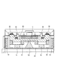
- A-A 'sectional view of FIG. 1 and FIG. 2 Diagram for explaining the direction of the magnetic force generated by the actuator, the direction of the current, the direction of the Lorentz force, and the rotational moment
- FIG. 1 The perspective view which shows the attachment state of the magnet to a yoke
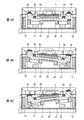
- FIG. 9A is a diagram showing a state of rotation of the holder (diffraction grating)
- FIG. 9A is a diagram showing no current flow through the coil
- FIG. 9B is a diagram showing a current flow in the direction shown in FIG. 9C shows a state in which a current is applied to the coil in the direction opposite to the direction shown in FIG. 7
- FIG. 10A, FIG. 10B, and FIG. 10C are diagrams for explaining the rotational position detection using the optical sensor and the reflection plate.
- FIG. 11A is a view showing an example of the configuration of the optical sensor
- FIG. 11B is a graph showing the relationship between the distance from the optical sensor to the reflector and the output current ratio
- FIG. 1 is a perspective view showing the entire configuration of a single-axis rotary actuator 100 (hereinafter simply referred to as “actuator”) according to an embodiment of the present invention
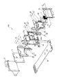
- FIG. 2 is an exploded perspective view of the actuator 100.
- the actuator 100 rotates the diffraction grating 1 in one axial direction to change the wavelength of light reaching the slit (not shown) through the diffraction grating 1 according to the rotation angle of the diffraction grating 1 It has become.
- an application example of the actuator 100 shown in FIG. 1 to a spectroscope will be described later with reference to FIG.
- the direction of the reflection surface of the diffraction grating 1 is referred to as the front surface direction
- the direction opposite to the reflection surface is referred to as the back surface direction.
- the actuator 100 includes the fixed angle 2, the base 3, the magnet 10, the fixing portion 20, the plate spring 30, the coil 40, the holder 50, the spacer 60, and the cover 70. It has an optical sensor 80 and a flexible printed circuit board 90.
- the fixed angle 2 has a substantially L-shaped cross-sectional shape, and the components of the actuator 100 are attached to the front surface, and the lower surface is fixed to a predetermined fixing surface. Thus, the actuator 100 is attached to a predetermined surface via the fixed angle 2.
- the fixing portion 20 is composed of a frame 21 and a yoke 22 for holding the magnet 10.
- the frame 21 is formed with a recessed bearing 21 a that holds the rotation shaft 52 of the holder 50.
- the yoke 22 has a U-shaped cross-sectional shape, and is fitted to the frame 21 while holding the magnet 10.
- the fixing portion 20 is attached to the fixed angle 2 through the base 3.
- the magnet 10 includes two magnets 11 and 12 attached to the bottom of the yoke 22 at a predetermined distance, and two magnets 13 and 14 attached to face the side of the yoke 22.
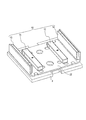
- the attachment of the magnet 10 to the yoke 22 is shown in FIG.
- the magnets 11 and 12 are attached to the yoke 22 such that the S pole is directed to the yoke 22 side and the N pole is directed to the surface side.
- the magnets 13 and 14 are attached to the yoke 22 such that the N pole is directed to the yoke side and the S pole is directed to the surface side, that is, the S poles face each other.
- the N pole and the S pole may all be reversed from those in FIG.
- the magnets 11 and 12 are attached to the yoke 22 so that the N pole is directed to the yoke 22 side and the S pole is directed to the surface side, and the S poles are oriented to the yoke side and the magnets 13 and 14 are N It may be attached to the yoke 22 so that the poles are oriented, that is, the N poles face each other.
- the frame 21 has a substantially square outer shape, and a leaf spring 30 is attached to the edge of the frame 21. Further, the holder 50 and the coil 40 fixed to the holder 50 are disposed in the hollow portion of the frame 21.
- the plate spring 30 has an outer peripheral portion 31 fixed to the frame 21 of the fixed portion 20, an inner peripheral portion 32 fixed to the holder 50, an outer peripheral portion 31 and an inner peripheral portion 32 as is apparent from FIG. And an arm portion 33 having elasticity to connect with each other.
- the holder 50 has a holder main body 51 having a substantially square outer shape, a rotary shaft 52 protruding in the vertical direction from the holder main body 51, and a reflection plate 53 attached to the rotary shaft 52.
- a mounting surface for mounting the diffraction grating 1 is formed on the surface side of the holder main body 51, and the diffraction grating 1 is fixed to the mounting surface by adhesion.
- the diffraction grating 1 is bonded to the mounting surface of the holder body 51 together with the spacer 60 in a state of being positioned by being fitted into the opening 61 of the spacer 60.
- the reflection plate 53 is disposed such that the main surface is present on the surface of the holder main body 51 extended from the main surface.
- FIG. 4 The state which attached the leaf
- the outer peripheral portion 31 of the plate spring 30 is fixed to the edge of the frame 21.
- the holder main body 51 is disposed in the hollow portion of the frame 21.
- the holder 50 is rotatable around the rotation shaft 52 by the rotation shaft 52 being axially supported by the bearing 21 a of the frame 21.
- the protrusion 54 of the holder 50 is fitted to the inner circumferential portion 32 of the plate spring 30.
- the holder 50 is rotatable about the rotation shaft 52 and is biased by the plate spring 30 so as to return to the neutral position as shown in FIG. 4.
- the coil 40 is attached to the back surface side of the holder main body 51.
- the state is shown in FIG.
- the two air core coils 41 and 42 are fixed to the back surface of the holder body 51 at a predetermined distance.
- currents in opposite directions flow in the respective coils 41 and 42. Specifically, in FIG. 5, a clockwise current flows in the coil 41, and a counterclockwise current flows in the coil 42.
- the plate spring 30 is made of a material with good conductivity such as metal, and the coil 40 is supplied with electricity via the plate spring 30.
- a feed portion (not shown) of the flexible printed circuit board 90 is connected to the outer peripheral portion 31 of the plate spring 30, and a coil 41 is formed on the inner peripheral portion 32 of the plate spring 30.
- the 42 terminals 40a and 40b are connected.
- the inner circumferential portion 32 and the terminals 40a and 40b are soldered.
- power can be supplied from the flexible printed circuit board 90 to the coil 40 which is a movable portion through the plate spring 30.
- the plate spring 30 also has a feeding function, the feeding system can be simplified, and the miniaturization of the apparatus can be promoted.
- FIG. 6 is an A-A ′ cross section of FIG. 1 and FIG. 2 (at the time of assembly) cut by a line passing through the center of the diffraction grating 1.
- the air core coil 41 is disposed above the rectangular magnet 11, and the air core coil 42 is disposed above the rectangular magnet 12. Further, the magnet 13 is disposed on the side of the coil 41, and the magnet 14 is disposed on the side of the coil 42.
- the magnets 11 and 12 alternately enter the air core portions of the air core coils 41 and 42.
- the magnets 11 and 12 are at the air core portions of the air core coils 41 and 42 in the state of a rotation angle of 0 ° shown in FIG. It is disposed slightly shifted from the center toward the rotating shaft.
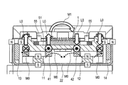
- FIG. 7 shows the direction of the magnetic force M0, the direction of the current, the direction of the Lorentz force L0, and the rotational moment M1 generated by the actuator 100.
- a magnetic force M0 is generated from the magnet 11 on the bottom of the yoke 22 toward the magnet 13 on the side of the yoke 22, and a magnetic force M0 is generated from the magnet 12 on the bottom of the yoke 22 to the magnet 14 on the side of the yoke 22.
- a magnetic force M0 is generated from each of the magnets 11 and 12 in the central direction of the yoke 22.
- Lorentz force L0 is generated in the coils 41, 42.
- FIG. 8 shows the relationship between the current value flowing through each of the coils 41 and 42 and the rotation angle of the holder 50 (diffraction grating 1).
- the holder 50 (diffraction grating 1) rotates to a position where the rotational moment according to the value of the current flowing through the coils 41 and 42 and the biasing force of the plate spring 30 are balanced. Then, at a certain rotation angle (6.5 ° in the example of FIG. 8), the protrusion 55 of the holder 50 abuts on the back surface of the cover 70, and the rotation of the holder 50 is stopped.
- a certain rotation angle 6.5 ° in the example of FIG. 8
- FIG. 9 is a view showing a rotation state of the holder 50 (diffraction grating 1).
- FIG. 9A shows a state in which no current flows through the coils 41 and 42, and the holder 50 (diffraction grating 1) is brought into a neutral (ie, rotation angle 0 °) state by the biasing force of the plate spring 30.
- FIG. 9B shows a state in which current flows in the direction shown in FIG. 7 in each of the coils 41 and 42, and the holder 50 (diffraction grating 1) is rotated in the clockwise direction in the drawing.
- FIG. 9C shows a state in which current flows in the direction opposite to the direction shown in FIG.
- the holder 50 (diffraction grating 1) can be rotationally driven clockwise and counterclockwise about the neutral position of FIG. 9A by changing the direction of the current supplied by the coils 41 and 42. ing.
- the rotational position of the holder 50 (diffraction grating 1) is detected by the optical sensor 80 attached to the fixed angle 2, and the detection result is sent to the control unit (not shown) via the flexible printed circuit board 90.
- the control unit controls the rotation of the holder 50 (diffraction grating 1) by supplying current values corresponding to the detection result to the coils 41 and 42 through the flexible printed circuit board 90.
- the optical sensor 80 emits light toward the reflecting plate 53 and detects the amount of reflected light to detect the rotational position. It has become. That is, the amount of light of the reflected light increases as the distance from the optical sensor 80 to the reflection plate 53 decreases, so the rotational position can be determined based on the amount of light.
- FIG. 11A shows a configuration example of the optical sensor 80.
- the optical sensor 80 emits light by the light emitting diode 81, receives the reflected light from the reflecting plate by the phototransistor 82, and obtains an output current according to the amount of reflected light.
- FIG. 11B is a graph showing the relationship between the distance from the optical sensor 80 to the reflection plate 53 and the output current ratio (the output current when the maximum light amount is obtained is 100%).
- the rotational position is detected by one optical sensor 80.
- 180 may be provided. Then, as shown in FIG. 13, by taking the difference between the sensor outputs L80 and L180 obtained by these optical sensors 80 and 180, it is possible to obtain a linear sensor output L1.
- FIG. 14 is a graph showing the torque generated by the actuator 100 of the present embodiment.
- FIG. 14 shows the torque that is generated particularly when the current in the direction as shown in FIG. 7 is supplied.
- the torque of the coil 41 rotating away from the magnet 11 decreases as the rotation angle increases, while the torque of the coil 42 rotating closer to the magnet 12 increases as the rotation angle increases.
- the decrease in torque of the coil 41 rotating away from the magnet 11 is compensated by the increase in torque of the coil 42 rotating closer to the magnet 12.
- the total torque does not decrease extremely as the rotation angle increases but becomes substantially flat.
- the rotatable range of the holder 50 (diffraction grating 1) is set to -6.5 ° to + 6.5 °, and substantially flat torque is generated in this rotatable range. It can be done.
- the rotatable range is not limited to this, and may be configured to rotate by ⁇ 6.5 ° or more. For example, the lower the protrusion 55 of the holder 50, the larger the rotation.
- FIG. 15 shows a spectrum when white light is split by rotating the diffraction grating 1 with a grating pitch of 1.5 ⁇ m. It can be seen from FIG. 15 that if the diffraction grating 1 can be rotated by 10.3 ° or more, it is possible to diffract the entire visible light range.
- the actuator 100 according to the present embodiment can rotate the diffraction grating 1 in the range of -6.5 ° to + 6.5 °, that is, 13 °, so that it is possible to diffract the entire visible light range. It is.
- the holder 50 having the mounting surface to which the diffraction grating 1 is attached and the rotation shaft 52, and the fixing portion 20 having the bearing 21a for holding the rotation shaft 52 of the holder 50.
- an elastic member a leaf spring comprising an outer peripheral portion 31 fixed to the fixed portion 20, an inner peripheral portion 32 fixed to the holder 50, and an elastic arm portion 33 connecting the outer peripheral portion 31 and the inner peripheral portion 32
- a drive unit having a coil 40 provided in the holder 50 and a magnet 10 provided in the fixed unit 20, to rotationally drive an optical element such as the diffraction grating 1 in one axial direction
- a suitable, small-sized, high-precision single-axis rotary actuator 100 can be realized.
- any wavelength component in incident light can be extracted. That is, if the incident light is white, components such as blue, green and red can be taken out according to the angle at which the diffraction grating 1 is stopped, so it can also be used as a wavelength variable light source.
- the air core dual coil 41, 42 is disposed to be accommodated on the back surface of the holder 50, and the magnets 11, 12 enter the air core portion of the coils 41, 42, so the magnetic efficiency is high and the XY size is high. Can realize a small one-axis rotary actuator 100.
- the diffraction grating 1 can be performed only by attaching it to the mounting surface of the holder 50, the diffraction grating 1 of various shapes can be applied easily.
- the spacer 60 in which the opening 61 corresponding to the shape of the diffraction grating 1 is formed the diffraction grating 1 of various sizes and shapes can be easily coped with.
- the device can be miniaturized as compared with the case of using a rotary encoder or the like.
- the configuration for detecting the angle is not limited to this.
- a rotary encoder may be used, a Hall element may be used, and the angle may be detected by detecting the drive current with a shunt resistor.
- the angle may be detected by measuring the inductance of the coils 41 and 42. That is, when the rotation angle changes, the magnetic flux passing through the coils 41 and 42 changes and the inductance changes, so that the angle can be detected by measuring this inductance.
- a detection coil may be provided in addition to the drive coil, and the rotation angle may be detected by measuring the induced electromotive force generated in the detection coil.
- the optical sensor may be stored and arranged inside the actuator.
- the shape of the yoke is not limited to this.
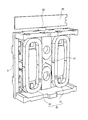
- the shape of the yoke may be, for example, as shown in FIG. That is, the yoke 122 may have a shape having a convex portion at the central portion. As a result, the magnetic flux in the vicinity of the convex portion can be strengthened, so that a larger rotational torque can be generated.
- the configuration of the coil, the yoke and the magnet is not limited to the configuration of the above embodiment, and may be, for example, a configuration as shown in FIG.
- one air core coil 140 is provided on the back surface side of the holder 50, and first and second yokes 222-1 and 222-2 are provided to sandwich the air core coil 140. It is done.
- Magnets 13 and 14 are provided on the first and second yokes 222-1 and 222-2, respectively.
- the holder 50 (diffraction grating 1) can be rotated by supplying a current to the coil 140.
- the shape of the grating grooves of the diffraction grating 1 attached to the holder 50 may be a rectangular shape, a sawtooth shape, a sine wave shape, or the like. Further, the diffraction grating 1 attached to the holder 50 may have a concave reflection surface. By using such a diffraction grating, light diffracted by the diffraction grating can be made to enter the slit without providing a condenser lens system.
- a transmission type may be used as the diffraction grating 1.
- an opening or a notch may be formed in the holder 50 or the yoke 22 for the light transmitted through the diffraction grating 1 to pass.
- a fulcrum member 152 is provided on the lower side (back side) of the position to be the rotational axis of the holder 50, and the fulcrum member 152 resists the holder 50 against the biasing force of the plate spring 30. You may hold it so that it may lift. In this way, the holder 50 can be rotated with the fulcrum member 152 as the rotation axis.
- FIG. 19 is a plan view showing the configuration of a spectroscope 200 using the actuator 100 according to the above-described embodiment.
- the light L 1 emitted from an optical unit (not shown) is incident on the diffraction grating 1 attached to the actuator 100 via the reflection mirror 201.
- the light diffracted by the diffraction grating 1 is directed to a slit portion 203 provided with a slit (not shown) via a reflection mirror 202.
- the light separated by passing through the slit is emitted from the light outlet 204.
- the dispersed light can be used as light for measuring biological information such as urine components and blood components, for example.
- the actuator 100 can rotationally drive the diffraction grating 1 without resonating at 70 to 80 Hz, so that biological information such as urine components and blood components can be measured in a short time. It is possible to realize spectral performance suitable for
- the optical element attached to the holder 50 is not limited to the diffraction grating 1, and for example, a mirror or the like may be attached.
- actuator 100 of the above-mentioned embodiment can also be used not only as an actuator of a spectroscope, for example as actuators, such as a rotation mechanism for changing light distribution of a headlight for cars.
- the single-axis rotary actuator of the present invention can be used, for example, as an actuator that rotationally drives a diffraction grating of a spectroscope.
Landscapes
- Physics & Mathematics (AREA)
- Spectroscopy & Molecular Physics (AREA)
- General Physics & Mathematics (AREA)
- Engineering & Computer Science (AREA)
- Power Engineering (AREA)
- Manufacturing & Machinery (AREA)
- Optics & Photonics (AREA)
- Mechanical Light Control Or Optical Switches (AREA)
- Spectrometry And Color Measurement (AREA)
- Optical Recording Or Reproduction (AREA)
Abstract
アクチュエーター100は、回折格子1が取り付けられる載置面と回転軸52とを有するホルダ50と、ホルダ50の回転軸52を保持する軸受21aを有する固定部20と、固定部20に固定される外周部31とホルダ50に固定される内周部32と外周部31と内周部32とを接続する弾性を有する腕部33とからなる弾性部材(板バネ30)と、ホルダ50に設けられるコイル40と固定部20に設けられる磁石10とを有する駆動部と、を備える。
Description
本発明は、例えば回折格子などの光学素子を1軸方向に回転駆動するための1軸回転アクチュエーターに関する。
モノクロメーターにおいては、回折格子をアクチュエーターによって回転駆動することにより、スリットに到達する光の波長を変化させるようになっている。このアクチュエーターとしては、ステッピングモーターやサインバー機構などが多く用いられている。
また、光学素子を駆動するアクチュエーターとして、例えば特許文献1で開示されたものがある。特許文献1には、板バネを介してベースに保持されたミラーを、コイル、磁石およびヨークを用いて磁気駆動することにより、ミラーを高精度に駆動できる小型のミラーチルトアクチュエーターが開示されている。
ところで、ステッピングモーターやサインバー機構などを用いた従来のモノクロメーターは、小型化には適していなかった。すなわち、ステッピングモーターは比較的大型であり、さらにステッピングモーターの回転分解能がモノクロメーターの分光性能を満たさない場合は減速器(ギア)が必要となるのでさらに大型化する。同様に、サインバー機構は、リードスクリューが必要なので大型化し、小型化には適さない。
一方で、特許文献1のアクチュエーターは、組み立てる部品点数の数が多いので、その分だけ組み立てが煩雑化し、さらに組み立て精度が悪いと駆動精度も悪くなるので、高精度の組み立て精度が要求されると考えられる。つまり、多くの部品を高精度で組み立てるための手間と時間が要求される。さらに、特許文献1のアクチュエーターは、1軸方向に駆動することもできるが、基本的には2軸方向の駆動も想定した構成となっているので、1軸方向専用のアクチュエーターに比べると、ブレなどが生じ易いと考えられる。
本発明は、以上の点を考慮してなされたものであり、回折格子などの光学素子を1軸方向に回転駆動するのに適した、小型で高精度の1軸回転アクチュエーターを提供する。
本発明の1軸回転アクチュエーターの一つの態様は、
光学素子が取り付けられる載置面と、回転軸と、を有するホルダと、
前記ホルダの前記回転軸を保持する軸受を有する固定部と、
前記固定部に固定される外周部と、前記ホルダに固定される内周部と、前記外周部と前記内周部とを接続する弾性を有する腕部と、からなる弾性部材と、
前記ホルダに設けられるコイルと、前記固定部に設けられる磁石と、を有する駆動部と、
を具備する。
光学素子が取り付けられる載置面と、回転軸と、を有するホルダと、
前記ホルダの前記回転軸を保持する軸受を有する固定部と、
前記固定部に固定される外周部と、前記ホルダに固定される内周部と、前記外周部と前記内周部とを接続する弾性を有する腕部と、からなる弾性部材と、
前記ホルダに設けられるコイルと、前記固定部に設けられる磁石と、を有する駆動部と、
を具備する。
本発明によれば、回折格子などの光学素子を1軸方向に回転駆動するのに適した、小型で高精度の1軸回転アクチュエーターを実現できる。
以下、本発明の実施の形態について、図面を参照して詳細に説明する。
図1は本発明の実施の形態に係る1軸回転アクチュエーター100(以下、単に「アクチュエーター」と呼ぶ)の全体構成を示す斜視図であり、図2はアクチュエーター100の分解斜視図である。アクチュエーター100は、回折格子1を1軸方向に回転駆動することにより、回折格子1を介してスリット(図示せず)に到達する光の波長を回折格子1の回転角度に応じて変化させるようになっている。因みに、図1に示したアクチュエーター100の分光器への応用例については、図19を用いて後述する。なお、以下の説明では、回折格子1の反射面の方向を表面方向とし、反射面と反対側の方向を裏面方向とする。
図2から分かるように、アクチュエーター100は、固定アングル2と、ベース3と、磁石10と、固定部20と、板バネ30と、コイル40と、ホルダ50と、スペーサ60と、カバー70と、光学センサー80と、フレキシブルプリント基板90と、を有する。
固定アングル2は、略L字状の断面形状でなり、前面にアクチュエーター100の各部品が取り付けられるとともに、下面が所定の固定面に固定されるようになっている。これにより、アクチュエーター100は固定アングル2を介して所定の面に取り付けられる。
固定部20は、枠体21と、磁石10を保持するヨーク22と、から構成されている。枠体21には、ホルダ50の回転軸52を保持する凹み形状の軸受21aが形成されている。ヨーク22は、コ字状の断面形状でなり、磁石10を保持した状態で枠体21に嵌め合わされる。固定部20は、ベース3を介して固定アングル2に取り付けられる。
磁石10は、ヨーク22の底面に所定の間隔をおいて取り付けられる2つの磁石11、12と、ヨーク22の側面に向かい合うように取り付けられる2つの磁石13、14とからなる。磁石10のヨーク22への取り付け状態を、図3に示す。磁石11、12は、ヨーク22側にS極が向き、表面側にN極が向くようにヨーク22に取り付けられている。磁石13、14は、ヨーク側にN極が向き、表面側にS極が向くように、つまりS極同士が向かい合うようにヨーク22に取り付けられている。なお、図3とはN極およびS極が全て逆になっていてもよい。つまり、磁石11、12は、ヨーク22側にN極が向き、表面側にS極が向くようにヨーク22に取り付けられ、磁石13、14は、ヨーク側にS極が向き、表面側にN極が向くように、つまりN極同士が向かい合うようにヨーク22に取り付けられていてもよい。
枠体21は外形が略正方形状でなり、枠体21の縁部には板バネ30が取り付けられる。また、枠体21の中空部分には、ホルダ50およびホルダ50に固定されたコイル40が配置される。
板バネ30は、図4からも明らかなように、固定部20の枠体21に固定される外周部31と、ホルダ50に固定される内周部32と、外周部31と内周部32とを接続する弾性を有する腕部33と、から構成されている。
ホルダ50は、外形が略正方形状でなるホルダ本体51と、ホルダ本体51から上下方向に突出した回転軸52と、回転軸52に取り付けられた反射板53と、を有する。ホルダ本体51の表面側には回折格子1を載置するための載置面が形成されており、回折格子1はこの載置面に接着により固定される。実際には、回折格子1は、スペーサ60の開口61に嵌め込まれることによって位置決めされた状態で、スペーサ60とともにホルダ本体51の載置面に接着される。反射板53は、主面がホルダ本体51の主面を延長した面に存在するように配置されている。
枠体21に板バネ30およびホルダ50を取り付けた状態を、図4に示す。図からも分かるように、枠体21の縁部には板バネ30の外周部31が固定される。ホルダ本体51は枠体21の中空部分に配置される。この状態で、回転軸52が枠体21の軸受21aによって軸支されることにより、ホルダ50は回転軸52を中心にして回転自在とされている。また、ホルダ50の突起54が板バネ30の内周部32に嵌合されている。これにより、ホルダ50は、回転軸52を回転中心として回転自在とされているとともに、板バネ30によって図4に示すような中立位置に復帰するように付勢されている。
ホルダ本体51の裏面側には、コイル40が取り付けられている。その状態を、図5に示す。ホルダ本体51の裏面には、2つの空芯コイル41、42が所定の間隔をもって固定される。図中の矢印で示したように、各コイル41、42には互いに反対向きの電流が流れるようになっている。具体的には、図5においては、コイル41には時計方向の電流が流れており、コイル42には反時計方向の電流が流れている。
板バネ30は金属などの良導電性の材料からなり、コイル40への給電は板バネ30を介して行われる。具体的には、図4に示すように、板バネ30の外周部31にフレキシブルプリント基板90の給電部(図示せず)が接続されるとともに、板バネ30の内周部32にコイル41、42の端子40a、40bが接続される。実際には、内周部32と端子40a、40bは半田付けされる。これにより、フレキシブルプリント基板90から板バネ30を介して、可動部であるコイル40に対して給電を行うことができる。このように、板バネ30が給電機能も兼ね備えることにより、給電系統を簡素化でき、装置の小型化を促進できる。
図6は、回折格子1の中心を通る線で切った、図1および図2(組立時)のA-A’断面である。図6からも分かるように、直方形状の磁石11の上方には空芯コイル41が配置されるとともに、直方形状の磁石12の上方には空芯コイル42が配置される。また、コイル41の側方には磁石13が配置されるとともに、コイル42の側方には磁石14が配置される。ここで、後述する図9からも分かるように、ホルダ50が回転すると、磁石11、12は交互に空芯コイル41、42の空芯部分に入り込むようになる。このとき、磁石11、12とコイル41、42がぶつからないようにするために、図6に示す回転角0°の状態において、各磁石11、12は空芯コイル41、42の空芯部分の中央から若干回転軸側にシフトして配置されている。
図7は、アクチュエーター100で発生する、磁力M0の向き、電流の向き、ローレンツ力L0の向き、回転モーメントM1を示すものである。ヨーク22底面の磁石11からヨーク22側面の磁石13に向かって磁力M0が発生するとともに、ヨーク22底面の磁石12からヨーク22側面の磁石14に向かって磁力M0が発生する。また、各磁石11、12からヨーク22の中央方向に向かって磁力M0が発生する。これらの磁力M0とコイル41、42に流れる電流の向きに応じて、コイル41、42にはローレンツ力L0が発生する。具体的には、各コイル41、42に図に示した向きの電流を流すと、コイル41には上向きのローレンツ力L0が発生し、コイル42には下向きのローレンツ力L0が発生する。この結果、ホルダ本体51には矢印で示す回転モーメントM1が付与され、ホルダ50およびそれに固定された回折格子1が回転する。なお、各コイル41、42に図に示した向きと逆の電流を流すと、コイル41には下向きのローレンツ力L0が発生し、コイル42には上向きのローレンツ力L0が発生する。この結果、ホルダ本体51には矢印と逆向きの回転モーメントM1が付与され、ホルダ50およびそれに固定された回折格子1が矢印と逆向きに回転する。
ここで、ヨーク22側面に磁石13、14を設けたことにより、コイル41、42に磁束を集中させることができ、この結果、トルクの向上および消費電力の低減を実現できる。また、ヨーク22側面に磁石13、14を設けたことにより、特に回転軸から遠い位置で強い磁力を発生させることができ、これにより、コイル41、42は回転軸から遠い位置で強いローレンツ力L0を得ることができる。この結果、効率的に大きな回転モーメントM1を得ることができるようになる。ただし、磁石13、14を設けない構成を採用してもよい。このようにすると、磁石13、14を設けた場合と比較して、トルクが下がり消費電力が大きくなるというデメリットがあるが、サイズが小さくなるので小型化できるというメリットがある。
図8は、各コイル41、42に流す電流値と、ホルダ50(回折格子1)の回転角との関係を示す。ホルダ50(回折格子1)は、コイル41、42に流れる電流値に応じた回転モーメントと、板バネ30の付勢力とがつり合う位置まで回転する。そして、ある回転角になると(図8の例では6.5°)、ホルダ50の突起55がカバー70の裏面に突き当たってホルダ50の回転が停止する。このように、カバー70によってホルダ50の回転を規制するようにしたことにより、電気的な回転制御だけでなく機械的にも回転を規制することができるので、所定範囲を超えるような回転を確実に防止でき。また、回転軸52がカバー70によって覆われているので(図1)、ホルダ50の脱輪なども防止できる。
図9は、ホルダ50(回折格子1)の回転状態を示す図である。図9Aは、コイル41、42に電流を流さない状態を示すものであり、ホルダ50(回折格子1)は板バネ30の付勢力によって中立(すなわち回転角度0°)の状態とされる。図9Bは、各コイル41、42に図7に示した方向の電流を流した状態を示すものであり、ホルダ50(回折格子1)は図の時計方向に回転された状態とされる。図9Cは、各コイル41、42に図7に示した方向と逆方向の電流を流した状態を示すものであり、ホルダ50(回折格子1)は図の反時計方向に回転された状態とされる。このように、ホルダ50(回折格子1)は、コイル41、42の供給する電流の向きを変えることにより、図9Aの中立位置を回転中心として時計方向および反時計方向に回転駆動できるようになっている。
ホルダ50(回折格子1)の回転位置は、固定アングル2に取り付けられた光学センサー80によって検知され、検知結果がフレキシブルプリント基板90を介して制御部(図示せず)に送出される。制御部は、検知結果に応じた電流値をフレキシブルプリント基板90を介してコイル41、42に供給することにより、ホルダ50(回折格子1)の回転を制御する。
実際には、図10A、図10B、図10Cに示すように、光学センサー80は、反射板53に向けて光を照射し、反射光の光量を検出することにより、回転位置を検知するようになっている。つまり、光学センサー80から反射板53までの距離が近いほど、反射光の光量が大きくなるので、その光量に基づいて回転位置を求めることができる。
図11Aは、光学センサー80の構成例を示す。光学センサー80は、発光ダイオード81によって光を出射し、フォトトランジスタ82によって反射板からの反射光を受光して反射光量に応じた出力電流を得るようになっている。図11Bは、光学センサー80から反射板53までの距離と出力電流比(最大光量が得られたときの出力電流を100%としたもの)との関係を示すグラフである。
なお、実施の形態では、1つの光学センサー80によって回転位置を検出しているが、図12A、図12B、図12Cに示すように、回転軸52を中心とした左右両側の位置に光学センサー80、180を設けてもよい。そして、図13に示すように、これらの光学センサー80、180によって得られたセンサー出力L80、L180の差分をとることにより、線形なセンサー出力L1を得ることができるようになる。
図14は、本実施の形態のアクチュエーター100によって発生するトルクを示したグラフである。図14は、特に図7に示したような向きの電流を供給した場合に発生するトルクを示している。磁石11から離れる方に回転するコイル41のトルクは、回転角が大きくなるほど減少していく一方で、磁石12に近づく方に回転するコイル42のトルクは回転角が大きくなるほど大きくなる。よって、磁石11から離れる方に回転するコイル41のトルクの減少分は、磁石12に近づく方に回転するコイル42のトルクの増加によって補われる。この結果、合計トルクは、回転角が大きくなっても極端に減少せず、ほぼフラットなものとなる。特に、本実施の形態のアクチュエーター100では、ホルダ50(回折格子1)の回転可能範囲は-6.5°~+6.5°とされており、この回転可能範囲においてはほぼフラットなトルクを発生させることができる。勿論、回転可能範囲はこれに限らず、±6.5°以上回転する構成としてもよい。例えばホルダ50の突起55を低くすると、より大きく回転するようになる。
図15は、白色光を、格子ピッチが1.5μmの回折格子1を回転させて分光した場合のスペクトルを示す。図15から、回折格子1を10.3°以上回転させることができれば、可視光域全てを回折することが可能であることが分かる。本実施の形態のアクチュエーター100は、回折格子1を、-6.5°~+6.5°の範囲すなわち13°回転させることが可能となっているので、可視光域全てを回折することが可能である。
以上説明したように、本実施の形態によれば、回折格子1が取り付けられる載置面と回転軸52とを有するホルダ50と、ホルダ50の回転軸52を保持する軸受21aを有する固定部20と、固定部20に固定される外周部31とホルダ50に固定される内周部32と外周部31と内周部32とを接続する弾性を有する腕部33とからなる弾性部材(板バネ30)と、ホルダ50に設けられるコイル40と固定部20に設けられる磁石10とを有する駆動部と、を設けたことにより、回折格子1などの光学素子を1軸方向に回転駆動するのに適した、小型で高精度の1軸回転アクチュエーター100を実現できる。
また、回折格子1を任意の角度で停止させることができるので、入射光の中の任意の波長成分を取り出すことができる。つまり、入射光が白色ならば、回折格子1を停止させる角度に応じて、青、緑、赤などの成分を取り出すことができるので、波長可変光源としても使用できる。
また、ホルダ50の裏面に収まるように空芯2連コイル41、42を配置し、さらにコイル41、42の空芯部分に磁石11、12が入り込む構成としたので、磁気効率が高くかつXYサイズが小さい1軸回転アクチュエーター100を実現できる。
また、回折格子1の取り付けは、ホルダ50の載置面に取り付けるだけで行うことができるので、種々の形状の回折格子1を容易に適用できる。実際には、回折格子1の形状に応じた開口61が形成されたスペーサ60を用いることによって、様々なサイズおよび形状の回折格子1に容易に対応できる。
また、重量の重い磁石10は回転せず、重量の軽いコイル41、42が回転する、いわゆるムービングコイル方式を採用したことにより、小さいトルクで応答性の良い回転動作を行うことができる。さらに、回転軸52の樹脂材料と、その軸受21aの樹脂材料とを異なる材料とすれば、摺動性を改善できるので、より小さいトルクで応答性の良い回転動作を行うことができるようになる。
また、光学センサー80と反射板53とを用いて回転角を検知したことにより、ロータリーエンコーダなどを用いる場合と比較して、装置を小型化できる。ただし、角度を検出するための構成は、これに限らない。例えばロータリーエンコーダを用いてもよく、ホール素子を用いてもよく、駆動電流をシャント抵抗で検出することで角度を検出してもよい。さらにコイル41、42のインダクタンスを測ることで角度を検出してもよい。つまり、回転角度が変化するとコイル41、42を貫く磁束が変化してインダクタンスが変動するので、このインダクタンスを測定することで角度を検出することができる。さらに、駆動用コイルの他に検出用コイルを設け、この検出用コイルに発生する誘導起電力を測定することで回転角度を検出してもよい。さらに、光学センサーはアクチュエーターの内部に格納して配置してもよい。
なお上述の実施の形態では、例えば図3に示したように、ヨーク22を断面がコ字状の形状とした場合について述べたが、ヨークの形状はこれに限らない。ヨークの形状は、例えば図16に示すようなものであってもよい。つまり、ヨーク122は、中央部に凸部を有する形状としてもよい。これにより、凸部付近の磁束を強くできるので、より大きな回転トルクを発生させることができるようになる。
またコイル、ヨークおよび磁石の構成は、上述の実施の形態の構成に限らず、例えば図17に示すような構成でもよい。図17の構成においては、ホルダ50の裏面側に1つの空芯コイル140が設けられており、この空芯コイル140を挟むように第1および第2のヨーク222-1、222-2が設けられている。第1および第2のヨーク222-1、222-2にはそれぞれ磁石13、14が設けられている。これにより、コイル140に電流を流すことでホルダ50(回折格子1)を回転させることができる。
なお、ホルダ50に取り付けられる回折格子1の格子溝の形状は、矩形形状、鋸歯形状、正弦波形状などであり得る。また、ホルダ50に取り付けられる回折格子1は、反射面が凹面形状のものであってもよい。このような回折格子を用いることにより、集光レンズ系を設けなくても、回折格子によって回折された光をスリットに入射させることができるようになる。
さらに、回折格子1として透過型のものを用いてもよい。この場合には、ホルダ50やヨーク22に、回折格子1を透過した光が通過するための開口や切欠きを形成すればよい。
また上述の実施の形態では、ホルダ50の回転軸52を、固定部20の凹み形状の軸受21aに保持させることで1軸の回転を実現した場合について述べたが、軸受の構成はこれに限らず、例えば図18に示すように、ホルダ50の回転軸となる位置の下側(裏面側)に支点部材152を設け、この支点部材152によってホルダ50を板バネ30の付勢力に抗して持ち上げるように保持するようにしてもよい。このようにすれば、ホルダ50を支点部材152を回転軸として回転させることができるようになる。
図19は、上述の実施の形態のアクチュエーター100を用いた分光器200の構成を示す平面図である。図示しない光学ユニットから出射された光L1は、反射ミラー201を介してアクチュエーター100に取り付けられた回折格子1に入射する。回折格子1によって回折された光は、反射ミラー202を介して、図示しないスリットが設けられたスリット部203へと向けられる。そして、スリットを通過することで分光された光が、光出口204から出射される。この分光された光は、例えば尿中成分や血液成分などの生体情報を測定するための光として利用することができる。実験によれば、上述の実施の形態のアクチュエーター100は、70~80Hzにおいて共振することなく回折格子1を回転駆動することができるので、尿中成分や血液成分などの生体情報を短時間で測定するのに適した分光性能を実現できる。
さらに、ホルダ50に取り付けられる光学素子は回折格子1に限らず、例えばミラーなどを取り付けてもよい。そして、上述の実施の形態のアクチュエーター100は、分光器のアクチュエーターに限らず、例えば自動車用ヘッドライトの配光を変化させるための回転機構などのアクチュエーターとして用いることもできる。
上述の実施の形態は、本発明を実施するにあたっての具体化の一例を示したものに過ぎず、これらによって本発明の技術的範囲が限定的に解釈されてはならないものである。すなわち、本発明はその要旨、またはその主要な特徴から逸脱することの無い範囲で、様々な形で実施することができる。
2015年4月17日出願の特願2015-085056の日本出願に含まれる明細書、図面および要約書の開示内容は、すべて本願に援用される。
本発明の1軸回転アクチュエーターは、例えば分光器の回折格子を回転駆動するアクチュエーターとして用いることができる。
1 回折格子
10、11、12、13、14 磁石
20 固定部
21 枠体
21a 軸受
22、122、222-1、222-2 ヨーク
30 板バネ
31 外周部
32 内周部
33 腕部
40、41、42、140 空芯コイル
40a、40b 端子
50 ホルダ
51 ホルダ本体
52 回転軸
53 反射板
54、55 突起
60 スペーサ
70 カバー
80、180 光学センサー
90 フレキシブルプリント基板
100 アクチュエーター
152 支点部材
200 分光器
10、11、12、13、14 磁石
20 固定部
21 枠体
21a 軸受
22、122、222-1、222-2 ヨーク
30 板バネ
31 外周部
32 内周部
33 腕部
40、41、42、140 空芯コイル
40a、40b 端子
50 ホルダ
51 ホルダ本体
52 回転軸
53 反射板
54、55 突起
60 スペーサ
70 カバー
80、180 光学センサー
90 フレキシブルプリント基板
100 アクチュエーター
152 支点部材
200 分光器
Claims (4)
- 光学素子が取り付けられる載置面と、回転軸と、を有するホルダと、
前記ホルダの前記回転軸を保持する軸受を有する固定部と、
前記固定部に固定される外周部と、前記ホルダに固定される内周部と、前記外周部と前記内周部とを接続する弾性を有する腕部と、からなる弾性部材と、
前記ホルダに設けられるコイルと、前記固定部に設けられる磁石と、を有する駆動部と、
を具備する1軸回転アクチュエーター。 - 前記コイルは、前記光学素子の前記載置面の裏面側に設けられている、
請求項1に記載の1軸回転アクチュエーター。 - 前記弾性部材は導電性を有する材料からなり、前記コイルは前記弾性部材を介して給電される、
請求項1に記載の1軸回転アクチュエーター。 - 前記固定部は、前記軸受を有する枠体と、前記磁石を保持するヨークと、を有する、
請求項1から請求項3のいずれか一項に記載の1軸回転アクチュエーター。
Applications Claiming Priority (2)
| Application Number | Priority Date | Filing Date | Title |
|---|---|---|---|
| JP2015085056A JP5900682B1 (ja) | 2015-04-17 | 2015-04-17 | 1軸回転アクチュエーター |
| JP2015-085056 | 2015-04-17 |
Publications (1)
| Publication Number | Publication Date |
|---|---|
| WO2016166980A1 true WO2016166980A1 (ja) | 2016-10-20 |
Family
ID=55648293
Family Applications (1)
| Application Number | Title | Priority Date | Filing Date |
|---|---|---|---|
| PCT/JP2016/002016 Ceased WO2016166980A1 (ja) | 2015-04-17 | 2016-04-14 | 1軸回転アクチュエーター |
Country Status (3)
| Country | Link |
|---|---|
| JP (1) | JP5900682B1 (ja) |
| TW (1) | TWI709764B (ja) |
| WO (1) | WO2016166980A1 (ja) |
Cited By (1)
| Publication number | Priority date | Publication date | Assignee | Title |
|---|---|---|---|---|
| CN112867960A (zh) * | 2018-08-20 | 2021-05-28 | 奥普托图尼股份公司 | 用于增强图像分辨率或减少散斑噪声的光学设备 |
Families Citing this family (1)
| Publication number | Priority date | Publication date | Assignee | Title |
|---|---|---|---|---|
| JP6934319B2 (ja) * | 2017-05-08 | 2021-09-15 | 日本電産サンキョー株式会社 | ローリング用磁気駆動ユニットおよび振れ補正機能付き光学ユニット |
Citations (2)
| Publication number | Priority date | Publication date | Assignee | Title |
|---|---|---|---|---|
| JP2010146621A (ja) * | 2008-12-17 | 2010-07-01 | Mitsubishi Electric Corp | 光ピックアップ装置 |
| JP2014075171A (ja) * | 2012-07-12 | 2014-04-24 | Funai Electric Co Ltd | レンズ駆動装置及び光ディスク装置 |
Family Cites Families (5)
| Publication number | Priority date | Publication date | Assignee | Title |
|---|---|---|---|---|
| JPH05135391A (ja) * | 1991-04-22 | 1993-06-01 | Seiko Epson Corp | 光学式記録再生装置の精密角度変位機構及びその組立方法 |
| JP3505282B2 (ja) * | 1995-07-31 | 2004-03-08 | 株式会社東芝 | 光ヘッド装置および情報処理装置 |
| WO2007029643A1 (ja) * | 2005-09-07 | 2007-03-15 | Alps Electric Co., Ltd. | アクチュエータ及びこれを用いたホログラフィー装置 |
| CN101458383A (zh) * | 2007-12-11 | 2009-06-17 | 台达电子工业股份有限公司 | 投影系统及其光学致动器 |
| JP5564471B2 (ja) * | 2011-07-25 | 2014-07-30 | 日立コンシューマエレクトロニクス株式会社 | 焦点が可変なミラーおよび光ピックアップ |
-
2015
- 2015-04-17 JP JP2015085056A patent/JP5900682B1/ja active Active
-
2016
- 2016-04-14 WO PCT/JP2016/002016 patent/WO2016166980A1/ja not_active Ceased
- 2016-04-15 TW TW105111740A patent/TWI709764B/zh not_active IP Right Cessation
Patent Citations (2)
| Publication number | Priority date | Publication date | Assignee | Title |
|---|---|---|---|---|
| JP2010146621A (ja) * | 2008-12-17 | 2010-07-01 | Mitsubishi Electric Corp | 光ピックアップ装置 |
| JP2014075171A (ja) * | 2012-07-12 | 2014-04-24 | Funai Electric Co Ltd | レンズ駆動装置及び光ディスク装置 |
Cited By (3)
| Publication number | Priority date | Publication date | Assignee | Title |
|---|---|---|---|---|
| CN112867960A (zh) * | 2018-08-20 | 2021-05-28 | 奥普托图尼股份公司 | 用于增强图像分辨率或减少散斑噪声的光学设备 |
| US11880044B2 (en) | 2018-08-20 | 2024-01-23 | Optotune Ag | Optical device for enhancing resolution of an image or for reducing speckle noise |
| US12411349B2 (en) | 2018-08-20 | 2025-09-09 | Optotune Switzerland Ag | Optical device for enhancing resolution of an image or for reducing speckle noise |
Also Published As
| Publication number | Publication date |
|---|---|
| TWI709764B (zh) | 2020-11-11 |
| JP2016206298A (ja) | 2016-12-08 |
| TW201638629A (zh) | 2016-11-01 |
| JP5900682B1 (ja) | 2016-04-06 |
Similar Documents
| Publication | Publication Date | Title |
|---|---|---|
| US11650400B2 (en) | Rotational ball-guided voice coil motor | |
| US11131846B2 (en) | Single-axis rotary actuator | |
| KR102178093B1 (ko) | 스텝 모터 및 차량용 지침 계기 | |
| JP5900682B1 (ja) | 1軸回転アクチュエーター | |
| JP2005275375A (ja) | 光学モジュール及びカメラモジュール | |
| JP6561878B2 (ja) | 1軸回転アクチュエーター | |
| CN110870181B (zh) | 电机定位装置、电机及云台 | |
| JP6414267B2 (ja) | モータ | |
| JP7113631B2 (ja) | アクチュエータ、羽根駆動装置、撮像装置及び電子機器 | |
| JP2020126243A (ja) | 1軸回転アクチュエーター | |
| JP5117315B2 (ja) | プロジェクタ用絞り装置 | |
| JP2017194319A (ja) | 分光器および測定装置 | |
| JP5201935B2 (ja) | モータ及びこれを備えた装置 | |
| JP2006337918A (ja) | レンズ駆動装置 | |
| JP5090286B2 (ja) | プロジェクタ用絞り装置 | |
| JP2006044510A (ja) | ミラー及び角度検出装置 | |
| JP2006337917A (ja) | レンズ駆動装置 | |
| JP2001153606A (ja) | フォトセンサ、移動検出装置およびこれを備えた機器、カメラ | |
| WO2019102752A1 (ja) | アクチュエータ、羽根駆動装置、撮像装置及び電子機器 | |
| JP4057026B2 (ja) | 駆動装置及びその組立装置 | |
| JP2006337919A (ja) | レンズ駆動装置 | |
| CN117411273A (zh) | 旋转往复驱动促动器 | |
| CN117411271A (zh) | 旋转往复驱动促动器 | |
| JP2001339910A (ja) | 位置センサ付き有限回転型電動機 | |
| WO2011118397A1 (ja) | テラヘルツ光受発光モジュールおよびテラヘルツ光の偏光制御方法 |
Legal Events
| Date | Code | Title | Description |
|---|---|---|---|
| 121 | Ep: the epo has been informed by wipo that ep was designated in this application |
Ref document number: 16779774 Country of ref document: EP Kind code of ref document: A1 |
|
| NENP | Non-entry into the national phase |
Ref country code: DE |
|
| 122 | Ep: pct application non-entry in european phase |
Ref document number: 16779774 Country of ref document: EP Kind code of ref document: A1 |