WO2016163055A1 - 亜鉛めっき鋼板の隅肉溶接方法 - Google Patents
亜鉛めっき鋼板の隅肉溶接方法 Download PDFInfo
- Publication number
- WO2016163055A1 WO2016163055A1 PCT/JP2015/085244 JP2015085244W WO2016163055A1 WO 2016163055 A1 WO2016163055 A1 WO 2016163055A1 JP 2015085244 W JP2015085244 W JP 2015085244W WO 2016163055 A1 WO2016163055 A1 WO 2016163055A1
- Authority
- WO
- WIPO (PCT)
- Prior art keywords
- steel plate
- steel sheet
- welding method
- welding
- steel
- Prior art date
- Legal status (The legal status is an assumption and is not a legal conclusion. Google has not performed a legal analysis and makes no representation as to the accuracy of the status listed.)
- Ceased
Links
Images




Classifications
-
- B—PERFORMING OPERATIONS; TRANSPORTING
- B23—MACHINE TOOLS; METAL-WORKING NOT OTHERWISE PROVIDED FOR
- B23K—SOLDERING OR UNSOLDERING; WELDING; CLADDING OR PLATING BY SOLDERING OR WELDING; CUTTING BY APPLYING HEAT LOCALLY, e.g. FLAME CUTTING; WORKING BY LASER BEAM
- B23K9/00—Arc welding or cutting
- B23K9/02—Seam welding; Backing means; Inserts
-
- B—PERFORMING OPERATIONS; TRANSPORTING
- B23—MACHINE TOOLS; METAL-WORKING NOT OTHERWISE PROVIDED FOR
- B23K—SOLDERING OR UNSOLDERING; WELDING; CLADDING OR PLATING BY SOLDERING OR WELDING; CUTTING BY APPLYING HEAT LOCALLY, e.g. FLAME CUTTING; WORKING BY LASER BEAM
- B23K33/00—Specially-profiled edge portions of workpieces for making soldering or welding connections; Filling the seams formed thereby
-
- B—PERFORMING OPERATIONS; TRANSPORTING
- B23—MACHINE TOOLS; METAL-WORKING NOT OTHERWISE PROVIDED FOR
- B23K—SOLDERING OR UNSOLDERING; WELDING; CLADDING OR PLATING BY SOLDERING OR WELDING; CUTTING BY APPLYING HEAT LOCALLY, e.g. FLAME CUTTING; WORKING BY LASER BEAM
- B23K9/00—Arc welding or cutting
- B23K9/23—Arc welding or cutting taking account of the properties of the materials to be welded
Definitions
- the present invention relates to a fillet welding method for joining galvanized steel sheets by arc welding.
- galvanized steel sheets with high rust-preventing power have been used for steel sheets for automobile bodies and the like.
- spot welding and arc welding are used properly depending on the required welding strength.
- Measures against welding failure include a method of first cutting the galvanized surface of the welded portion and removing zinc from the welded portion. However, since a surface cutting step occurs, productivity deteriorates and costs increase. Next, there is a method of increasing the current during welding and increasing the welding temperature to accelerate the vaporization of zinc and reduce bubbles due to the vaporized zinc, but the viewpoint of preventing a part of the steel sheet from melting away at high temperatures Since manual work is required, productivity deteriorates and costs increase. In addition, there is a method in which the welding speed is slowed down, and the vaporization of zinc is accelerated by welding heat to reduce bubbles due to the vaporized zinc. However, since the welding speed is slowed down, the productivity is deteriorated and the cost is increased.
- the present invention has been made in view of the above-described points, and even when zinc is vaporized due to welding heat during arc welding of a galvanized steel sheet, the vaporized zinc is promptly released into the atmosphere. It is an object of the present invention to provide a fillet welding method for a galvanized steel sheet that can be arc-welded without leaving vaporized zinc bubbles in the weld metal.
- the fillet welding method for a galvanized steel sheet according to claim 1 made to solve this problem uses a galvanized steel sheet for one or both of the first steel sheet and the second steel sheet, and the first steel sheet and the first steel sheet.
- the fillet welding method for a galvanized steel sheet according to claim 2 is the fillet welding method for a galvanized steel sheet according to claim 1, wherein each groove of the first steel sheet is formed by coining. .
- the zinc vaporized from the first steel sheet and / or the second steel sheet is formed on the contact surface of the second steel sheet. It discharges
- the vaporized zinc is introduced into the atmosphere from a plurality of grooves arranged in parallel on the first steel plate. The gas is quickly discharged and the gas is vented in the entire joining region between the first steel plate and the second steel plate. As a result, arc welding can be performed without leaving vaporized zinc bubbles in the weld metal.
- each groove of the first steel plate is formed in the joining region of the first steel plate, it is easy to process. Therefore, the pretreatment work in arc welding can be simplified, productivity can be improved, and cost can be reduced.
- both end portions of each groove are exposed on both sides of the contact surface of the second steel plate, which is in contact with the contact surface of the second steel plate on the joining region of the first steel plate. This is realized. Accordingly, the second steel plate can be easily aligned with the first steel plate.
- the grooves arranged in parallel in the joining region of the first steel sheet are formed by coining, which is suitable for mass production such as cold forging and press work. It is possible to form each groove of the first steel plate with a simple process.
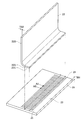
- FIG. 2 is a cross-sectional view of the first steel plate cut along line A1-A1 in FIG. It is a perspective view for demonstrating the fillet welding method of the galvanized steel plate which concerns on 1st Embodiment.
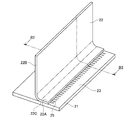
- FIG. 4 is a cross-sectional view of the first steel plate and the second steel plate cut along line B1-B1 in FIG. It is a perspective view for demonstrating the fillet welding method of the galvanized steel plate which concerns on 1st Embodiment.
- FIG. 4 is a cross-sectional view of the first steel plate and the second steel plate cut along line B1-B1 in FIG. It is a perspective view for demonstrating the fillet welding method of the galvanized steel plate which concerns on 1st Embodiment.
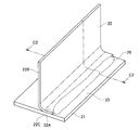
- FIG. 6 is a cross-sectional view of the first steel plate, the second steel plate, and the bead portion taken along line C1-C1 of FIG. It is a perspective view for demonstrating the fillet welding method of the galvanized steel plate which concerns on 2nd Embodiment of this invention.
- FIG. 8 is a cross-sectional view of the first steel plate taken along line A2-A2 of FIG. It is a perspective view for demonstrating the fillet welding method of the galvanized steel plate which concerns on 2nd Embodiment.
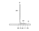
- FIG. 10 is a cross-sectional view of the first steel plate and the second steel plate taken along line B2-B2 of FIG.
- FIG. 12 is a cross-sectional view of the first steel plate, the second steel plate, and the bead portion taken along line C2-C2 of FIG.
- the first steel plate 11 and the second steel plate 12 are both galvanized steel plates.
- the plate thickness TA1 of the first steel plate 11 is thicker than the plate thickness TA2 of the second steel plate 12.
- a bonding region 14 is provided on the surface 13 of the first steel plate 11.
- the joining region 14 is a long region where the contact surface 12 ⁇ / b> A of the second steel plate 12 is abutted against the surface 13 of the first steel plate 11.
- a plurality of grooves 15 are formed in the entire joining region 14 by coining (for example, cold forging or pressing).
- Each groove 15 has a rectangular opening, and is formed on the surface 13 of the first steel plate 11 at a predetermined pitch so as to intersect the elongated joining region 14 at a substantially right angle.
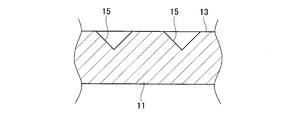
- the cross section of each groove 15 is an inverted triangle, as shown in FIG.
- both end portions 15 ⁇ / b> A and 15 ⁇ / b> B of each groove 15 of the first steel plate 11 are exposed on both sides of the contact surface 12 ⁇ / b> A of the second steel plate 12.
- each groove 15 of the first steel plate 11 is formed on the surface 13 of the first steel plate 11, it is easy to process. Therefore, the pretreatment work in arc welding can be simplified, productivity can be improved, and cost can be reduced.
- arc welding can be performed without leaving bubbles caused by vaporized zinc in the weld metal (bead portion 16) for welding the first steel plate 11 and the second steel plate 12, so that the burn-out or cracking during arc welding, etc. It is possible to avoid poor welding.
- the arcs are welded with the grooves 15 of the first steel sheet 11 on both sides of the second steel sheet 12. Both end portions 15A and 15B are exposed. This state is realized by bringing the contact surface 12A of the second steel plate 12 into contact with the surface 13 of the first steel plate 11 (see FIG. 1). Therefore, in the fillet welding method of the galvanized steel sheet according to the first embodiment, the second steel sheet 12 can be easily aligned with the first steel sheet 11.
- each groove 15 of the first steel sheet 11 is formed by coining, which is suitable for mass production such as cold forging and press working, etc.
- Each groove 15 of one steel plate 11 can be formed.
- the first steel plate 21 and the second steel plate 22 are galvanized steel plates.
- the plate thickness TB1 of the first steel plate 21 is thicker than the plate thickness TB2 of the second steel plate 22.
- the bent portion 22A of the second steel plate 22 is provided by being bent at a substantially right angle with respect to the vertical plate portion 22B of the second steel plate 22.
- a bonding region 24 is provided on the surface 23 of the first steel plate 21.
- the joining region 24 is a long region in which the contact surface 22 ⁇ / b> C of the bent portion 22 ⁇ / b> A of the second steel plate 22 contacts the surface 23 of the first steel plate 21.
- a plurality of grooves 25 are formed in the entire joining region 24 by coining (for example, cold forging or pressing).
- Each groove 25 has a rectangular opening, and is formed on the surface 23 of the first steel plate 21 at a predetermined pitch so as to intersect the elongated joining region 24 at a substantially right angle.
- the cross section of each groove 25 is an inverted triangle.
- both end portions 25 ⁇ / b> A and 25 ⁇ / b> B of each groove 25 of the first steel plate 21 are exposed on both sides of the contact surface 22 ⁇ / b> C of the bent portion 22 ⁇ / b> A of the second steel plate 22.
- the entire joining region 24 is arc-welded from the one end 25A side of each groove 25, as shown in FIG. 11 and FIG. 12, the surface 23 of the first steel plate 21 and the second steel plate A bead portion 26 is formed between the 22 bent portions 22A.
- the vaporized zinc is removed from the plurality of grooves 25 arranged in parallel on the first steel plate 21.
- the gas is quickly released into the atmosphere and degassed in the entire joining region 24 of the first steel plate 21 and the second steel plate 22.
- arc welding can be performed without leaving the vaporized zinc bubbles in the weld metal (bead portion 26).
- each groove 25 of the first steel plate 21 is formed on the surface 23 of the first steel plate 21, it is easy to process. Therefore, the pretreatment work in arc welding can be simplified, productivity can be improved, and cost can be reduced.
- arc welding can be performed without leaving bubbles caused by vaporized zinc in the weld metal (bead portion 26) for welding the first steel plate 21 and the second steel plate 12, so that burn-off or cracking during arc welding, etc. It is possible to avoid poor welding.
- the grooves 25 of the first steel sheet 21 are formed on both sides of the second steel sheet 22 during arc welding. Both end portions 25A and 25B are in an exposed state. This state is realized by bringing the contact surface 22C of the bent portion 22A of the second steel plate 22 into contact with the surface 23 of the first steel plate 21 (see FIG. 7). Therefore, in the fillet welding method for a galvanized steel sheet according to the second embodiment, the second steel sheet 22 can be easily aligned with the first steel sheet 21.
- each groove 25 of the first steel sheet 21 is formed by coining, which is suitable for mass production such as cold forging and pressing, and is inexpensive.
- Each groove 25 of one steel plate 21 can be formed.
- both the first steel sheets 11 and 21 and the second steel sheets 12 and 22 are galvanized steel sheets.
- 21 and the second steel plates 12, 22 may be galvanized steel plates.
- the grooves 15 and 25 provided in the first steel sheets 11 and 21 may be formed at irregular pitches, and the cross section thereof. May not be an inverted triangle.
Landscapes
- Engineering & Computer Science (AREA)
- Mechanical Engineering (AREA)
- Physics & Mathematics (AREA)
- Plasma & Fusion (AREA)
- Chemical & Material Sciences (AREA)
- Materials Engineering (AREA)
- Butt Welding And Welding Of Specific Article (AREA)
- Arc Welding In General (AREA)
Abstract
亜鉛めっき鋼板のアーク溶接時に溶接熱に起因して亜鉛が気化した場合においても、気化した亜鉛を大気中に速やかに放出することを可能とし、気化した亜鉛による気泡を溶接金属内に残存させることなく、アーク溶接することができる亜鉛めっき鋼板の隅肉溶接方法を提供する。 先ず、第1鋼板11と第2鋼板12の接合領域14の全体に渡って並設された複数の溝15を第1鋼板11の表面13に形成する。次に、第1鋼板11の表面13に第2鋼板12の当接面12Aを当接させることにより、第1鋼板11の各溝15に第2鋼板12を交差させる。次に、第2鋼板12の両側で第1鋼板11の各溝15の両端部15A、15Bを露出させた状態で接合領域14をアーク溶接する。
Description
本発明は、亜鉛めっき鋼板をアーク溶接で接合する際の隅肉溶接方法に関する。
従来より、自動車のボディ等の鋼板には、防錆力の大きい亜鉛めっき鋼板が用いられる。亜鉛めっき鋼板の溶接には、要求される溶接強度に依って、スポット溶接とアーク溶接が使い分けられる。
亜鉛めっき鋼板をアーク溶接すると、鋼板表面の亜鉛が溶接熱で気化するので、溶接金属中に気化した亜鉛に起因して気泡が発生する。気化した亜鉛による気泡は、ビードにブローホールやピットを発生させる。ブローホールやピットは、ビードの強度が低下する溶接不良を起こす。溶接不良は、溶接される母材の双方が亜鉛めっき鋼板である場合に限らず、溶接される母材の一方が亜鉛めっき鋼板である場合にも起きる。
溶接不良の対策としては、先ず、溶接部の亜鉛めっき表面を削り、溶接部から亜鉛を除去する方法があるが、表面削り工程が発生するため、生産性が悪化し、コストアップとなる。次に、溶接時の電流を上げ、溶接温度を高めることで亜鉛の気化を早くし、気化した亜鉛による気泡を減少させる方法があるが、鋼板の一部が高温で溶け落ちすることを防ぐ観点から手作業が必要なため、生産性が悪化し、コストアップとなる。また、溶接スピードを遅くし、溶接熱で亜鉛の気化を進ませ、気化した亜鉛による気泡を減少させる方法があるが、溶接スピードが遅くなるため、生産性が悪化し、コストアップとなる。
このような問題を改善するため、下記特許文献1に記載された隅肉溶接法が提案されている。下記特許文献1に記載の隅肉溶接法では、隅肉継手を溶接するに当り、溶接部材の一方に断面方向で深さp、長さpの寸法を有し、q/p≧1、p×q≧1mm2を満足する開先を設け、且つ溶融金属の最奥部先端の継手ルートに強制的に断面積で0.25mm2以上の未溶着部を設けて、柱状ブローホールの生成を防止する。
しかしながら、上記特許文献1に記載の隅肉溶接法を亜鉛めっき鋼板のアーク溶接に適用するには、亜鉛めっき鋼板の端面に開先を設ける必要があるが、亜鉛めっき鋼板は自動車等のボディで使用される薄板であることから、亜鉛めっき鋼板の端面に開先を設けることは困難であり、特許文献1に記載の隅肉溶接法を適用することは難しい。
そこで、本発明は、上述した点を鑑みてなされたものであり、亜鉛めっき鋼板のアーク溶接時に溶接熱に起因して亜鉛が気化した場合においても、気化した亜鉛を大気中に速やかに放出することを可能とし、気化した亜鉛による気泡を溶接金属内に残存させることなく、アーク溶接することができる亜鉛めっき鋼板の隅肉溶接方法を提供することを課題とする。
この課題を解決するためになされた請求項1に係る亜鉛めっき鋼板の隅肉溶接方法は、第1鋼板と第2鋼板の一方又は両方に亜鉛めっき鋼板を使用し、前記第1鋼板と前記第2鋼板の接合領域をアーク溶接する亜鉛めっき鋼板の隅肉溶接方法であって、前記第1鋼板における接合領域の全体に複数の溝を並設し、前記第2鋼板の当接面が各溝と交差するように第2鋼板の当接面を第1鋼板の接合領域に当接し、前記第2鋼板の当接面の両側で各溝の両端部が露出した状態で前記接合領域をアーク溶接することを特徴とする。
請求項2に係る亜鉛めっき鋼板の隅肉溶接方法は、請求項1に記載する亜鉛めっき鋼板の隅肉溶接方法であって、前記第1鋼板の各溝をコイニングで形成することを特徴とする。
請求項1に係る発明の亜鉛めっき鋼板の隅肉溶接方法では、接合領域のアーク溶接が行われると、第1鋼板及び/又は第2鋼板から気化した亜鉛は、第2鋼板の当接面の両側で露出した第1鋼板の各溝の両端部のうち、アーク溶接が行われる側とは反対側の端部から放出される。このように、アーク溶接時に溶接熱に起因して第1鋼板及び/又は第2鋼板から亜鉛が気化した場合においても、気化した亜鉛は第1鋼板に並設された複数の各溝から大気中に速やかに放出されて第1鋼板と第2鋼板の接合領域の全体でガス抜きが行われる。これにより、気化した亜鉛による気泡を溶接金属内に残存させることなく、アーク溶接することができる。
さらに、第1鋼板の各溝は、第1鋼板における接合領域に形成されるため、加工し易い。従って、アーク溶接における前処理作業を簡素化して、生産性が向上するとともにコストの低減を図ることができる。
また、アーク溶接時には、各溝の両端部は、第2鋼板の当接面の両側で露出した状態にあり、その状態は、第1鋼板の接合領域に第2鋼板の当接面を当接させることにより実現する。従って、第1鋼板に対する第2鋼板の位置合わせを容易に行うことができる。
請求項2に係る発明の亜鉛めっき鋼板の隅肉溶接方法では、第1鋼板の接合領域に並設される各溝をコイニングで形成しており、冷間鍛造やプレス加工等といった量産に適し安価な加工で第1鋼板の各溝を形成することが可能である。
本発明に係る亜鉛めっき鋼板の隅肉溶接方法について、本発明を具体化した第1実施形態、第2実施形態に基づき、図面を参照しつつ詳細に説明する。
[1.第1実施形態]
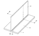
先ず、第1実施形態に係る亜鉛めっき鋼板の隅肉溶接方法について説明する。第1実施形態に係る亜鉛めっき鋼板の隅肉溶接方法では、図1に表されたように、第1鋼板11の表面13(平面)に対して第2鋼板12の当接面12Aが突き合わされるようにして、第1鋼板11と第2鋼板12がT字形にアーク溶接される。
先ず、第1実施形態に係る亜鉛めっき鋼板の隅肉溶接方法について説明する。第1実施形態に係る亜鉛めっき鋼板の隅肉溶接方法では、図1に表されたように、第1鋼板11の表面13(平面)に対して第2鋼板12の当接面12Aが突き合わされるようにして、第1鋼板11と第2鋼板12がT字形にアーク溶接される。
第1鋼板11と第2鋼板12は、共に亜鉛めっき鋼板である。第1鋼板11の板厚TA1は、第2鋼板12の板厚TA2より厚い。
第1鋼板11の表面13には、接合領域14が設けられる。接合領域14は、第1鋼板11の表面13に対して第2鋼板12の当接面12Aが突き合わされる長尺状の領域である。
接合領域14の全体には、複数の溝15がコイニング(例えば、冷間鍛造やプレス加工等)で形成される。各溝15は、長方形状の開口を有し、長尺状の接合領域14とは略直角で交わるように、第1鋼板11の表面13に所定ピッチで形成される。各溝15の断面は、図2に表されたように、逆三角形である。
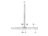
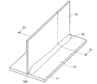
第1実施形態に係る亜鉛めっき鋼板の隅肉溶接方法では、上述したように、先ず、図1や図2に表されたように、接合領域14の全体に渡って並設された複数の溝15を第1鋼板11の表面13に形成する。次に、図3に表されたように、第1鋼板11の表面13に第2鋼板12の当接面12Aを当接させることにより、第1鋼板11の各溝15に対して第2鋼板12の当接面12Aを交差させる。次に、図4に表されたように、第2鋼板12の当接面12Aの両側で第1鋼板11の各溝15の両端部15A,15Bを露出させた状態にする。この状態を維持して、各溝15の一端部15Aの側から接合領域14の全体をアーク溶接すると、図5や図6に表されたように、第1鋼板11の表面13と第2鋼板12との間に溶接材によるビード部16が形成される。
このようにしてアーク溶接が行われる際、第1鋼板11及び第2鋼板12から気化した亜鉛は、第2鋼板12の当接面12Aの両側で露出した第1鋼板11の各溝15の両端部15A,15Bのうち、アーク溶接が行われる一端部15Aとは反対側の他端部15Bから放出される(図6参照)。
このように、アーク溶接時に溶接熱に起因して第1鋼板11及び第2鋼板12から亜鉛が気化した場合においても、気化した亜鉛は第1鋼板11に並設された複数の各溝15から大気中に速やかに放出されて第1鋼板11と第2鋼板12の接合領域14の全体でガス抜きが行われる。これにより、気化した亜鉛による気泡を溶接金属(ビード部16)内に残存させることなく、アーク溶接することができる。
さらに、第1鋼板11の各溝15は、第1鋼板11の表面13に形成されるため、加工し易い。従って、アーク溶接における前処理作業を簡素化して、生産性が向上するとともにコストの低減を図ることができる。
さらに、第1実施形態に係る発明の亜鉛めっき鋼板の隅肉溶接方法では、第1鋼板11及び第2鋼板12に対して、より高い温度にすることなく、また、より多くの熱を与えることなく、第1鋼板11と第2鋼板12を溶接する溶接金属(ビード部16)中に気化した亜鉛に起因する気泡を残存させずにアーク溶接が行えるので、アーク溶接時の溶け落ちや割れ等の溶接不良を回避することが可能である。
図3や図4に表されたように、第1実施形態に係る発明の亜鉛めっき鋼板の隅肉溶接方法では、アーク溶接時には、第2鋼板12の両側で第1鋼板11の各溝15の両端部15A,15Bが露出した状態にある。この状態は、第1鋼板11の表面13に第2鋼板12の当接面12Aを当接させることにより実現する(図1参照)。従って、第1実施形態に係る発明の亜鉛めっき鋼板の隅肉溶接方法では、第1鋼板11に対する第2鋼板12の位置合わせを容易に行うことができる。
第1実施形態に係る発明の亜鉛めっき鋼板の隅肉溶接方法では、第1鋼板11の各溝15をコイニングで形成しており、冷間鍛造やプレス加工等といった量産に適し安価な加工で第1鋼板11の各溝15を形成することが可能である。
[2.第2実施形態]
次に、第2実施形態に係る亜鉛めっき鋼板の隅肉溶接方法について説明する。第2実施形態に係る亜鉛めっき鋼板の隅肉溶接方法では、図7に表されたように、第1鋼板21の表面23に対して第2鋼板22の曲折部22Aを当接させるようにして、第1鋼板21と第2鋼板22がT字形にアーク溶接される。
次に、第2実施形態に係る亜鉛めっき鋼板の隅肉溶接方法について説明する。第2実施形態に係る亜鉛めっき鋼板の隅肉溶接方法では、図7に表されたように、第1鋼板21の表面23に対して第2鋼板22の曲折部22Aを当接させるようにして、第1鋼板21と第2鋼板22がT字形にアーク溶接される。
第1鋼板21と第2鋼板22は、亜鉛めっき鋼板である。第1鋼板21の板厚TB1は、第2鋼板22の板厚TB2より厚い。第2鋼板22の曲折部22Aは、第2鋼板22の縦板部22Bに対して略直角に折り曲げられることにより設けられる。
第1鋼板21の表面23には、接合領域24が設けられる。接合領域24は、第1鋼板21の表面23に対して第2鋼板22の曲折部22Aの当接面22Cを当接させる長尺状の領域である。
接合領域24の全体には、複数の溝25がコイニング(例えば、冷間鍛造やプレス加工等)で形成される。各溝25は、長方形状の開口を有し、長尺状の接合領域24とは略直角で交わるように、第1鋼板21の表面23に所定ピッチで形成される。各溝25の断面は、図8に表されたように、逆三角形である。
第2実施形態に係る亜鉛めっき鋼板の隅肉溶接方法では、上述したように、先ず、図7や図8に表されたように、接合領域24の全体に渡って並設された複数の溝25を第1鋼板21の表面23に形成する。次に、図9に表されたように、第1鋼板21の表面23に第2鋼板22の曲折部22Aの当接面22Cを当接させることにより、第1鋼板21の各溝25に第2鋼板22の曲折部22Aの当接面22Cを交差させる。次に、図10に表されたように、第2鋼板22の曲折部22Aの当接面22Cの両側で第1鋼板21の各溝25の両端部25A,25Bを露出させた状態にする。この状態を維持して、各溝25の一端部25Aの側から接合領域24の全体をアーク溶接すると、図11や図12に表されたように、第1鋼板21の表面23と第2鋼板22の曲折部22Aとの間にビード部26が形成される。
このようにしてアーク溶接が行われると、第1鋼板21及び第2鋼板22から気化した亜鉛は、第2鋼板22の曲折部22Aの当接面22Cの両側で露出した第1鋼板21の各溝25の両端部25A,25Bのうち、アーク溶接が行われる一端部25Aとは反対側の他端部25Bから放出される(図12参照)。
このように、アーク溶接時に溶接熱に起因して第1鋼板21及び第2鋼板22から亜鉛が気化した場合においても、気化した亜鉛は第1鋼板21に並設された複数の各溝25から大気中に速やかに放出されて第1鋼板21と第2鋼板22の接合領域24の全体でガス抜きが行われる。これにより、気化した亜鉛による気泡を溶接金属(ビード部26)内に残存させることなく、アーク溶接することができる。
さらに、第1鋼板21の各溝25は、第1鋼板21の表面23に形成されるため、加工し易い。従って、アーク溶接における前処理作業を簡素化して、生産性が向上するとともにコストの低減を図ることができる。
さらに、第2実施形態に係る発明の亜鉛めっき鋼板の隅肉溶接方法では、第1鋼板21及び第2鋼板22に対して、より高い温度にすることなく、また、より多くの熱を与えることなく、第1鋼板21と第2鋼板12を溶接する溶接金属(ビード部26)中に気化した亜鉛に起因する気泡を残存させずにアーク溶接が行えるので、アーク溶接時の溶け落ちや割れ等の溶接不良を回避することが可能である。
図9や図10に表されたように、第2実施形態に係る発明の亜鉛めっき鋼板の隅肉溶接方法では、アーク溶接時には、第2鋼板22の両側で第1鋼板21の各溝25の両端部25A,25Bが露出した状態にある。この状態は、第1鋼板21の表面23に第2鋼板22の曲折部22Aの当接面22Cを当接させることにより実現する(図7参照)。従って、第2実施形態に係る発明の亜鉛めっき鋼板の隅肉溶接方法では、第1鋼板21に対する第2鋼板22の位置合わせを容易に行うことができる。
第2実施形態に係る発明の亜鉛めっき鋼板の隅肉溶接方法では、第1鋼板21の各溝25をコイニングで形成しており、冷間鍛造やプレス加工等といった量産に適し安価な加工で第1鋼板21の各溝25を形成することが可能である。
[3.その他]
尚、本発明は上記実施形態に限定されるものでなく、その趣旨を逸脱しない範囲で様々な変更が可能である。
例えば、第1実施形態や第2実施形態に係る亜鉛めっき鋼板の隅肉溶接方法では、第1鋼板11,21と第2鋼板12,22の双方が亜鉛めっき鋼板であるが、第1鋼板11,21と第2鋼板12,22の一方が亜鉛めっき鋼板であってもよい。
尚、本発明は上記実施形態に限定されるものでなく、その趣旨を逸脱しない範囲で様々な変更が可能である。
例えば、第1実施形態や第2実施形態に係る亜鉛めっき鋼板の隅肉溶接方法では、第1鋼板11,21と第2鋼板12,22の双方が亜鉛めっき鋼板であるが、第1鋼板11,21と第2鋼板12,22の一方が亜鉛めっき鋼板であってもよい。
第1実施形態や第2実施形態に係る亜鉛めっき鋼板の隅肉溶接方法では、第1鋼板11,21に設けられる各溝15,25は、不規則なピッチで形成されてもよく、その断面が逆三角形でなくてもよい。
11 第1鋼板
12 第2鋼板
12A 第2鋼板の当接面
13 第1鋼板の表面
14 接合領域
15 溝
15A,15B 第1鋼板の各溝の両端
21 第1鋼板22 第2鋼板
22A 第2鋼板の曲折部
22C 第2鋼板の当接面
23 第1鋼板の表面
24 接合領域
25 溝
25A,25B 第1鋼板の各溝の両端
12 第2鋼板
12A 第2鋼板の当接面
13 第1鋼板の表面
14 接合領域
15 溝
15A,15B 第1鋼板の各溝の両端
21 第1鋼板22 第2鋼板
22A 第2鋼板の曲折部
22C 第2鋼板の当接面
23 第1鋼板の表面
24 接合領域
25 溝
25A,25B 第1鋼板の各溝の両端
Claims (2)
- 第1鋼板と第2鋼板の一方又は両方に亜鉛めっき鋼板を使用し、前記第1鋼板と前記第2鋼板の接合領域をアーク溶接する亜鉛めっき鋼板の隅肉溶接方法であって、
前記第1鋼板における接合領域の全体に複数の溝を並設し、
前記第2鋼板の当接面が各溝と交差するように第2鋼板の当接面を第1鋼板の接合領域に当接し、
前記第2鋼板の当接面の両側で各溝の両端部が露出した状態で前記接合領域をアーク溶接することを特徴とする亜鉛めっき鋼板の隅肉溶接方法。 - 請求項1に記載する亜鉛めっき鋼板の隅肉溶接方法であって、
前記第1鋼板の各溝をコイニングで形成することを特徴とする亜鉛めっき鋼板の隅肉溶接方法。
Applications Claiming Priority (2)
| Application Number | Priority Date | Filing Date | Title |
|---|---|---|---|
| JP2015-080571 | 2015-04-10 | ||
| JP2015080571A JP2016198796A (ja) | 2015-04-10 | 2015-04-10 | 亜鉛めっき鋼板の隅肉溶接方法 |
Publications (1)
| Publication Number | Publication Date |
|---|---|
| WO2016163055A1 true WO2016163055A1 (ja) | 2016-10-13 |
Family
ID=57072427
Family Applications (1)
| Application Number | Title | Priority Date | Filing Date |
|---|---|---|---|
| PCT/JP2015/085244 Ceased WO2016163055A1 (ja) | 2015-04-10 | 2015-12-16 | 亜鉛めっき鋼板の隅肉溶接方法 |
Country Status (2)
| Country | Link |
|---|---|
| JP (1) | JP2016198796A (ja) |
| WO (1) | WO2016163055A1 (ja) |
Cited By (2)
| Publication number | Priority date | Publication date | Assignee | Title |
|---|---|---|---|---|
| JP2019217546A (ja) * | 2018-06-22 | 2019-12-26 | 株式会社神戸製鋼所 | めっき鋼板の接合方法及び接合構造体 |
| JP2020131273A (ja) * | 2019-02-25 | 2020-08-31 | 株式会社神戸製鋼所 | めっき鋼板の接合方法及び接合構造体 |
Families Citing this family (3)
| Publication number | Priority date | Publication date | Assignee | Title |
|---|---|---|---|---|
| JP6965230B2 (ja) * | 2018-11-14 | 2021-11-10 | 豊田鉄工株式会社 | 車両構成部材 |
| US20230082468A1 (en) * | 2020-02-26 | 2023-03-16 | Nippon Steel Corporation | T-joint, building structure, and method of manufacturing t-joint |
| JP7412256B2 (ja) * | 2020-04-07 | 2024-01-12 | プレス工業株式会社 | ドアインパクトビーム構造 |
Citations (4)
| Publication number | Priority date | Publication date | Assignee | Title |
|---|---|---|---|---|
| JPH05212405A (ja) * | 1992-01-31 | 1993-08-24 | Sumitomo Metal Ind Ltd | 隅肉溶接性に優れためっき鋼板 |
| JPH07164066A (ja) * | 1993-12-10 | 1995-06-27 | Japan Steel Works Ltd:The | コイニング加工方法 |
| JPH0947873A (ja) * | 1995-08-02 | 1997-02-18 | Komatsu Ltd | 重ね合わせ溶接方法、装置及び溶接鋼板 |
| JPH09136161A (ja) * | 1995-11-13 | 1997-05-27 | Kanto Auto Works Ltd | アークスポット溶接方法 |
-
2015
- 2015-04-10 JP JP2015080571A patent/JP2016198796A/ja active Pending
- 2015-12-16 WO PCT/JP2015/085244 patent/WO2016163055A1/ja not_active Ceased
Patent Citations (4)
| Publication number | Priority date | Publication date | Assignee | Title |
|---|---|---|---|---|
| JPH05212405A (ja) * | 1992-01-31 | 1993-08-24 | Sumitomo Metal Ind Ltd | 隅肉溶接性に優れためっき鋼板 |
| JPH07164066A (ja) * | 1993-12-10 | 1995-06-27 | Japan Steel Works Ltd:The | コイニング加工方法 |
| JPH0947873A (ja) * | 1995-08-02 | 1997-02-18 | Komatsu Ltd | 重ね合わせ溶接方法、装置及び溶接鋼板 |
| JPH09136161A (ja) * | 1995-11-13 | 1997-05-27 | Kanto Auto Works Ltd | アークスポット溶接方法 |
Cited By (10)
| Publication number | Priority date | Publication date | Assignee | Title |
|---|---|---|---|---|
| JP2019217546A (ja) * | 2018-06-22 | 2019-12-26 | 株式会社神戸製鋼所 | めっき鋼板の接合方法及び接合構造体 |
| WO2019244605A1 (ja) * | 2018-06-22 | 2019-12-26 | 株式会社神戸製鋼所 | めっき鋼板の接合方法及び接合構造体 |
| EP3791988A4 (en) * | 2018-06-22 | 2021-07-21 | Kabushiki Kaisha Kobe Seiko Sho (Kobe Steel, Ltd.) | METHOD OF CONNECTING CLADED STEEL SHEET AND CONNECTING STRUCTURE |
| US11982307B2 (en) | 2018-06-22 | 2024-05-14 | Kobe Steel, Ltd. | Method for joining plated steel sheet and joint structure |
| JP2020131273A (ja) * | 2019-02-25 | 2020-08-31 | 株式会社神戸製鋼所 | めっき鋼板の接合方法及び接合構造体 |
| WO2020174883A1 (ja) * | 2019-02-25 | 2020-09-03 | 株式会社神戸製鋼所 | めっき鋼板の接合方法及び接合構造体 |
| KR20210113386A (ko) * | 2019-02-25 | 2021-09-15 | 가부시키가이샤 고베 세이코쇼 | 도금 강판의 접합 방법 및 접합 구조체 |
| CN113453833A (zh) * | 2019-02-25 | 2021-09-28 | 株式会社神户制钢所 | 镀敷钢板的接合方法以及接合结构体 |
| JP7267770B2 (ja) | 2019-02-25 | 2023-05-02 | 株式会社神戸製鋼所 | めっき鋼板の接合方法及び接合構造体 |
| KR102588203B1 (ko) * | 2019-02-25 | 2023-10-13 | 가부시키가이샤 고베 세이코쇼 | 도금 강판의 접합 방법 및 접합 구조체 |
Also Published As
| Publication number | Publication date |
|---|---|
| JP2016198796A (ja) | 2016-12-01 |
Similar Documents
| Publication | Publication Date | Title |
|---|---|---|
| JP4494496B2 (ja) | 抵抗溶接方法及び溶接構造体 | |
| WO2016163055A1 (ja) | 亜鉛めっき鋼板の隅肉溶接方法 | |
| KR101554800B1 (ko) | 레이저 용접 강관의 제조 방법 | |
| JP5866790B2 (ja) | レーザ溶接鋼管の製造方法 | |
| JP2009119485A (ja) | 溶接形鋼の製造方法 | |
| US11982307B2 (en) | Method for joining plated steel sheet and joint structure | |
| JP6505359B2 (ja) | Zn系めっき鋼板製部材のアーク溶接方法 | |
| US20160039039A1 (en) | Aluminum resistance spot welding tip and method of making the same | |
| JP6382593B2 (ja) | 溶接方法 | |
| JP2012135796A (ja) | 突き合わせ溶接方法 | |
| JP2006224137A (ja) | 補剛板及び補剛板の製造方法 | |
| JP5231073B2 (ja) | 溶接継手及びその製造方法 | |
| JP2008536689A (ja) | 保護層で被覆されたシートをレーザ透過溶着により接合する方法 | |
| JP4232024B2 (ja) | 溶接ビード構造及び溶接方法 | |
| KR20170123551A (ko) | 플래시버트 용접을 이용한 강판의 접합 방법 | |
| JP4786401B2 (ja) | 突合せ溶接金属板の製造方法 | |
| US20230082468A1 (en) | T-joint, building structure, and method of manufacturing t-joint | |
| JP6117025B2 (ja) | 積層鉄心の製造方法 | |
| JP2000246445A (ja) | めっき鋼板の溶接方法 | |
| JP6965230B2 (ja) | 車両構成部材 | |
| CN100467185C (zh) | 对焊装置及对焊方法 | |
| JP7733435B2 (ja) | 溶接用部材及びその製造方法、並びに溶接構造体の製造方法 | |
| JP7747678B2 (ja) | 部材の製造方法 | |
| JP6617443B2 (ja) | 金属部材の溶接方法 | |
| JP7792308B2 (ja) | ランオフプレート及びランオフプレートを用いた溶接加工方法 |
Legal Events
| Date | Code | Title | Description |
|---|---|---|---|
| 121 | Ep: the epo has been informed by wipo that ep was designated in this application |
Ref document number: 15888546 Country of ref document: EP Kind code of ref document: A1 |
|
| NENP | Non-entry into the national phase |
Ref country code: DE |
|
| 122 | Ep: pct application non-entry in european phase |
Ref document number: 15888546 Country of ref document: EP Kind code of ref document: A1 |