WO2016162908A1 - 舶用液化ガスタンク及びそれを備える液化ガス運搬船 - Google Patents
舶用液化ガスタンク及びそれを備える液化ガス運搬船 Download PDFInfo
- Publication number
- WO2016162908A1 WO2016162908A1 PCT/JP2015/005184 JP2015005184W WO2016162908A1 WO 2016162908 A1 WO2016162908 A1 WO 2016162908A1 JP 2015005184 W JP2015005184 W JP 2015005184W WO 2016162908 A1 WO2016162908 A1 WO 2016162908A1
- Authority
- WO
- WIPO (PCT)
- Prior art keywords
- tank
- tank body
- liquefied gas
- formula
- central axis
- Prior art date
- Legal status (The legal status is an assumption and is not a legal conclusion. Google has not performed a legal analysis and makes no representation as to the accuracy of the status listed.)
- Ceased
Links
Images


Classifications
-
- B—PERFORMING OPERATIONS; TRANSPORTING
- B63—SHIPS OR OTHER WATERBORNE VESSELS; RELATED EQUIPMENT
- B63B—SHIPS OR OTHER WATERBORNE VESSELS; EQUIPMENT FOR SHIPPING
- B63B25/00—Load-accommodating arrangements, e.g. stowing, trimming; Vessels characterised thereby
- B63B25/02—Load-accommodating arrangements, e.g. stowing, trimming; Vessels characterised thereby for bulk goods
- B63B25/08—Load-accommodating arrangements, e.g. stowing, trimming; Vessels characterised thereby for bulk goods fluid
- B63B25/12—Load-accommodating arrangements, e.g. stowing, trimming; Vessels characterised thereby for bulk goods fluid closed
- B63B25/16—Load-accommodating arrangements, e.g. stowing, trimming; Vessels characterised thereby for bulk goods fluid closed heat-insulated
-
- F—MECHANICAL ENGINEERING; LIGHTING; HEATING; WEAPONS; BLASTING
- F17—STORING OR DISTRIBUTING GASES OR LIQUIDS
- F17C—VESSELS FOR CONTAINING OR STORING COMPRESSED, LIQUEFIED OR SOLIDIFIED GASES; FIXED-CAPACITY GAS-HOLDERS; FILLING VESSELS WITH, OR DISCHARGING FROM VESSELS, COMPRESSED, LIQUEFIED, OR SOLIDIFIED GASES
- F17C3/00—Vessels not under pressure
- F17C3/02—Vessels not under pressure with provision for thermal insulation
- F17C3/025—Bulk storage in barges or on ships
-
- F—MECHANICAL ENGINEERING; LIGHTING; HEATING; WEAPONS; BLASTING
- F17—STORING OR DISTRIBUTING GASES OR LIQUIDS
- F17C—VESSELS FOR CONTAINING OR STORING COMPRESSED, LIQUEFIED OR SOLIDIFIED GASES; FIXED-CAPACITY GAS-HOLDERS; FILLING VESSELS WITH, OR DISCHARGING FROM VESSELS, COMPRESSED, LIQUEFIED, OR SOLIDIFIED GASES
- F17C2201/00—Vessel construction, in particular geometry, arrangement or size
- F17C2201/01—Shape
-
- F—MECHANICAL ENGINEERING; LIGHTING; HEATING; WEAPONS; BLASTING
- F17—STORING OR DISTRIBUTING GASES OR LIQUIDS
- F17C—VESSELS FOR CONTAINING OR STORING COMPRESSED, LIQUEFIED OR SOLIDIFIED GASES; FIXED-CAPACITY GAS-HOLDERS; FILLING VESSELS WITH, OR DISCHARGING FROM VESSELS, COMPRESSED, LIQUEFIED, OR SOLIDIFIED GASES
- F17C2221/00—Handled fluid, in particular type of fluid
- F17C2221/03—Mixtures
- F17C2221/032—Hydrocarbons
- F17C2221/033—Methane, e.g. natural gas, CNG, LNG, GNL, GNC, PLNG
-
- F—MECHANICAL ENGINEERING; LIGHTING; HEATING; WEAPONS; BLASTING
- F17—STORING OR DISTRIBUTING GASES OR LIQUIDS
- F17C—VESSELS FOR CONTAINING OR STORING COMPRESSED, LIQUEFIED OR SOLIDIFIED GASES; FIXED-CAPACITY GAS-HOLDERS; FILLING VESSELS WITH, OR DISCHARGING FROM VESSELS, COMPRESSED, LIQUEFIED, OR SOLIDIFIED GASES
- F17C2270/00—Applications
- F17C2270/01—Applications for fluid transport or storage
- F17C2270/0102—Applications for fluid transport or storage on or in the water
- F17C2270/0105—Ships
Definitions
- the present invention relates to a marine liquefied gas tank that stores liquefied gas and a liquefied gas carrier equipped with the marine liquefied gas tank.
- liquefied gas such as liquefied natural gas (hereinafter referred to as “LNG”)
- LNG liquefied natural gas
- a liquefied gas carrier ship equipped with a plurality of liquefied gas tanks has been used.
- a liquefied gas tank mounted on a liquefied gas carrier ship for example, an independent spherical tank, a membrane type tank, and the like are known.
- Patent Document 1 discloses an independent spherical tank (hereinafter referred to as “spherical tank”) mounted on an LNG carrier that carries LNG.
- a spherical tank as shown in FIGS. 1 and 2 of Patent Document 1 is a pressure vessel independent of a hull, and is supported on the hull by a skirt extending in a vertical direction from a foundation deck of the hull.
- the tank mounted on the LNG carrier has pressure resistance and heat resistance for storing cryogenic LNG in a high pressure state regardless of the type of tank, but there are advantages and disadvantages depending on the tank type.
- the spherical tank has a true spherical shape compared to other types of tanks, so it can be designed without the need for reinforcement on the inside, eliminating the stress concentration that is the source of cracks. There are advantages such as being able to.
- an object of the present invention is to provide a marine liquefied gas tank and a liquefied gas carrier equipped with the marine liquefied gas tank that can increase the load of liquefied gas as compared with a spherical tank, and can be easily designed to enjoy the advantages of the spherical tank. .
- a marine liquefied gas tank is a marine liquefied gas tank that is a symmetric pressure vessel around a vertical central axis, and has an upper tank body having a lower end that opens downward.
- m 1 (1)
- r 1 is the radius of the upper end or the lower end of the one tank body
- r 2 is the height of the one tank body
- m is a constant that satisfies 2 ⁇ m ⁇ 3.
- the value of m in Formula (1) is set to be larger than 2, one tank body has a shape bulging obliquely upward or downward from the tank center. As a result, the tank capacity can be increased compared to a true spherical tank. If the value of m in the formula (1) becomes too large, the tank shape on the one side of the tank body becomes close to a cylindrical shape, and as a result, aggregates or the like that reinforce flat portions are required.
- the value of m in the formula (1) is set to be smaller than 3 a tank structure that can withstand the pressure of the liquefied gas can be realized without a reinforcing material or with a small reinforcing material.
- the curvature of the trajectory represented by the formula (1) is continuous, the design that enjoys the advantages of the spherical tank can be easily performed.
- a vertical cross-sectional shape passing through the central axis of the other tank body of the upper tank body and the lower tank body may coincide with a locus represented by the following expression (2). .
- n 1 (2)
- r 3 is the height of the other tank body
- n is a constant that satisfies 2 ⁇ n ⁇ 3.
- the other tank body since the value of n in the formula (2) is set to be larger than 2, the other tank body has a shape bulging obliquely upward or downward from the tank center. Thereby, the tank capacity can be further increased.
- n in Equation (2) becomes too large, the tank shape on the other tank side becomes close to a cylindrical shape, and as a result, aggregates and the like that reinforce flat portions are required.
- n in Equation (2) is set to be smaller than 3, a tank structure that can withstand the pressure of the liquefied gas can be realized with no reinforcing material or with few reinforcing materials. Further, since the curvature of the trajectory represented by Expression (2) is continuous, the design that enjoys the advantages of the spherical tank can be easily performed.
- manufacture of a marine liquefied gas tank becomes easy.
- R 1 and r 2 in the formula (1) may satisfy 0.9 ⁇ r 2 / r 1 ⁇ 1.1. In this case, since the change in the curvature of the locus of equation (1) does not become extremely large, a design that further enjoys the advantages of the spherical tank becomes possible.
- the marine vessel liquefied gas tank may include a vertically extending cylindrical body connecting the upper tank body and the lower tank body between the upper tank body and the lower tank body. According to this configuration, the height of the cylindrical body is increased and the liquefied gas loading capacity of the liquefied gas tank is increased within the allowable range with respect to the visibility from the bridge and the position of the center of gravity of the liquefied gas transport ship equipped with this marine liquefied gas tank. Can be increased.
- a marine liquefied gas tank and a liquefied gas transport ship including the marine liquefied gas tank that can increase the load of liquefied gas as compared with the spherical tank and can easily enjoy the advantages of the spherical tank.
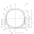
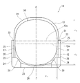
- FIG. 1 It is a side view of the liquefied gas carrier ship concerning the embodiment of the present invention. It is a top view of the liquefied gas carrier ship concerning the embodiment of the present invention. It is sectional drawing of the liquefied gas carrier ship shown in FIG. It is a figure which shows the modification of a marine liquefied gas tank.
- the liquefied gas conveyed by the liquefied gas carrier 1A is, for example, LNG or liquid hydrogen.
- the liquefied gas carrier 1 ⁇ / b> A of this embodiment includes a plurality (four in this example) of marine liquefied gas tanks (hereinafter simply referred to as “tanks”) 10 in the direction of the length of the hull 20. Further, the liquefied gas carrier 1A of this embodiment is provided with a bridge 21 at a rear portion (left side in FIG. 1), which is a place for maneuvering during voyage. As shown in FIG. 1, the upper portion of the tank 10 projects upward from the upper deck 22 of the hull 20.
- FIG. 3 is a cross-sectional view showing a tank 10 mounted on the liquefied gas carrier 1A and a structure for supporting it.
- a pair of longitudinal partition walls 25 extending in the ship length direction along the ship side skin 24 on both sides in the ship width direction of the hull 20 are provided inward from the pair of ship side skins 24 by a predetermined distance. Are disposed between the vertical partition walls 25.
- a foundation deck 26 that supports the tank 10 via a skirt 27 is provided around the tank 10.
- the foundation deck 26 is provided at a predetermined height position below the upper deck 22 in the hull 20, and the lower end portion of the longitudinal partition wall 25 is connected to the upper surface of the foundation deck 26.
- the foundation deck 26 is provided so as to connect the ship side outer plates 24 to each other in the ship width direction.
- the skirt 27 is cylindrical, and the lower end of the skirt 27 is connected to the upper surface of the foundation deck 26, and the upper end of the skirt 27 is connected to the outer peripheral surface of the tank 10.
- a circular opening having substantially the same size as the diameter of the skirt 27 is provided at a position where the tank 10 is provided in the foundation deck 26.
- an inner bottom plate 28 extending in the ship length direction along the ship bottom outer plate 23 is provided above the ship bottom outer plate 23 by a predetermined distance.
- a pair of bilge hopper plates 29 are provided between both ends of the inner bottom plate 28 in the ship width direction and the foundation deck 26.
- the bilge hopper plate 29 is also provided so as to extend in the captain direction.
- the bilge hopper plate 29 is inclined from both ends of the inner bottom plate 28 toward the outside in the ship width direction.
- the tank 10 is a pressure vessel symmetric about the vertical center axis C.
- the tank 10 includes a lower tank body 12 that forms a lower portion of the tank 10 and opens upward, and an upper tank body 13 that forms an upper portion of the tank 10 and opens downward.
- the tank 10 has a lower tank body 12 and an upper tank body 13 directly connected.
- the outer surfaces of the lower tank body 12 and the upper tank body 13 are covered with a heat insulating material (not shown).
- the lower tank body 12 is bowl-shaped and has an annular upper end portion 12a.
- the horizontal cross-sectional shape of the lower tank body 12 is annular, and the vertical cross-sectional shape of the lower tank body 12 passing through the central axis C matches the locus represented by the following formula (1).
- m 1 (1)
- r 1 is the radius of the upper end portion 12a of the lower tank body 12
- r 2 is the height of the lower tank body 12
- the value of m is 2.5, for example.
- the vertical axis is positive and the central axis C is set as the y axis, and the straight line on the horizontal plane passing through the upper end portion 12a of the lower tank body 12 and orthogonal to the central axis C is the x axis.
- the vertical cross-sectional shape of the lower tank body 12 passing through the central axis C matches the locus represented by the range of y ⁇ 0 in the above equation (1).
- Equation (1) The value of m in Equation (1) is not limited to 2.5, and any value may be used as long as 2 ⁇ m ⁇ 3. Since the value of m is larger than 2, the vertical cross-sectional shape of the lower tank body 12 is a shape bulging obliquely downward from the center of the tank 10.
- the upper tank body 13 has an inverted bowl shape and has an annular lower end portion 13a.
- the horizontal cross-sectional shape of the upper tank body 13 is annular, and the vertical cross-sectional shape of the upper tank body 13 passing through the central axis C matches the locus represented by the following formula (2).
- n 1 (2)
- r 1 is the radius of the lower end 13a of the upper tank 13
- r 3 is the height of the upper tank 13, the value of n is 2.5, for example.
- the vertical axis is positive and the central axis C is set to the y-axis, and the straight line on the horizontal plane passing through the lower end portion 13a of the upper tank body 13 and perpendicular to the central axis C is the x-axis.
- the vertical cross-sectional shape of the upper tank body 13 passing through the central axis C matches the locus represented by the range of y ⁇ 0 in the above equation (2).
- n in Formula (2) is not limited to 2.5, and any value may be used as long as 2 ⁇ n ⁇ 3. Since the value of n is larger than 2, the vertical cross-sectional shape of the upper tank body 13 is a shape bulging obliquely upward from the center of the tank 10. Further, the radius r 1 of the lower end portion 13 a of the upper tank body 13 is the same value as the radius r 1 of the upper end portion 12 a of the lower tank body 12.
- the tank cover 31 is supported by the upper deck 22.
- the tank cover 31 is arranged outside the tank 10 by a predetermined distance from the upper tank body 13 and has the same shape as the upper tank body 13.
- the tank cover 31 may have a shape different from that of the upper tank body 13.
- the vertical cross-sectional shape of the lower tank body 12 passing through the central axis C of the tank 10 matches the trajectory represented by the above equation (1).
- the value of m in the formula (1) is larger than 2, so the tank 10 The shape swells obliquely downward from the center. Thereby, the tank capacity can be increased by effectively utilizing the space between the tank 10 and the hull 20 (for example, the inner bottom plate 28 and the bilge hopper plate 29).
- the value of m in the formula (1) becomes too large, the shape of the lower part of the tank 10 becomes close to a cylindrical shape, and as a result, an aggregate or the like that reinforces a flat portion is required.
- the value of m in Equation (1) is set to be smaller than 3, a tank structure that can withstand the pressure of the liquefied gas can be realized with no reinforcing material or with few reinforcing materials.
- the curvature of the trajectory represented by the formula (1) is continuous, a design that takes advantage of the spherical tank that the reinforcing material is unnecessary or reduced can be easily performed.
- the vertical cross-sectional shape of the upper tank body 13 passing through the central axis C matches the locus represented by the expression (2).
- the value of n in the formula (2) is larger than 2, so that the tank 10 The shape swells obliquely upward from the center.
- the tank capacity can be increased within the allowable range with respect to the visibility from the bridge 21 and the position of the center of gravity of the liquefied gas carrier 1A.
- n in the formula (2) becomes too large, the shape of the upper part of the tank 10 becomes close to a cylindrical shape, and as a result, aggregates or the like that reinforce flat portions are required.
- n in Equation (2) is set to be smaller than 3, a tank structure that can withstand the pressure of the liquefied gas can be realized with no reinforcing material or with few reinforcing materials.
- curvature of the trajectory represented by Expression (2) is continuous, a design that can enjoy the advantage of the spherical tank that the reinforcing material is unnecessary or reduced can be easily performed.
- the value of m in the formula (1) and the value of n in the formula (2) are both 2.5, which is the same value, so the lower tank body 12 and the upper tank body 13 are the same. It becomes a shape and manufacture of the tank 10 becomes easy.
- FIG. 4 is a view showing a tank 50 which is a modification of the tank 10.
- the tank 50 as a modified example is a cylindrical body extending in the vertical direction connecting the upper tank body 13 and the lower tank body 12 between the upper tank body 13 and the lower tank body 12. 51.
- the upper end portion 12a of the lower tank body 12 and the lower end portion 13a of the upper tank body 13 are arranged on different horizontal planes. That is, the x-axis of each of the expressions (1) and (2) is also located on different horizontal planes. More specifically, the vertical axis is positive and the central axis C is set as the y axis, and the straight line on the horizontal plane passing through the upper end portion 12a of the lower tank body 12 and orthogonal to the central axis C is the x axis. , The vertical cross-sectional shape of the lower tank body 12 passing through the central axis C matches the locus represented by the range of y ⁇ 0 in the above equation (1).
- the liquefied gas load capacity of the tank 50 can be increased as the height of the cylindrical body 51 is increased.
- the visibility from the bridge 21 may be deteriorated and the stability of the liquefied gas carrier ship 1A may be deteriorated due to the center of gravity of the tank 50 moving upward.
- the height of the cylindrical body 51 is set within a range in which visibility from the bridge 21 can be sufficiently secured and allowed as the center of gravity position of the liquefied gas carrier ship 1A.
- the radius r 1 of the respective openings of the lower tank 12 and the upper tank 13, the height r 2 of the lower tank body 12, the height r 3 of the upper tank 13 Have the same length, but may be of different lengths.
- the ratio of r 1 and r 2 in the formula (1) preferably satisfies 0.9 ⁇ r 2 / r 1 ⁇ 1.1.
- the ratio of r 1 and r 3 in the formula (2) preferably satisfies 0.9 ⁇ r 3 / r 1 ⁇ 1.1.
- the value of m in the formula (1) and the value of n in the formula (2) are the same value, but may be different values.
- m in equation (1) may be any value as long as it is a constant satisfying 2 ⁇ m ⁇ 3.
- m in equation (1) is the same as that of lower tank body 12. The distance is set so that the hull 20 (for example, the inner bottom plate 28 and the bilge hopper plate 29) does not come into contact with the hull 20.
- n in the formula (2) may be any value as long as it is a constant satisfying 2 ⁇ n ⁇ 3.
- n in the formula (2) is the stability of the liquefied gas carrier 1A. Therefore, the position of the center of gravity of the liquefied gas carrier ship 1A when the tank 10 is fully loaded is set so that the property is maintained.
- the vertical cross-sectional shape which passes along the central axis C of one tank body of the upper tank body 13 and the lower tank body 12 of the tanks 10 and 50 is Formula (1) (however, 2 ⁇ m ⁇ You may be comprised so that it may correspond to the locus
- the other tank body of the upper tank body 13 and the lower tank body 12 may have the same shape as a conventional spherical tank.
Landscapes
- Engineering & Computer Science (AREA)
- Mechanical Engineering (AREA)
- Chemical & Material Sciences (AREA)
- Combustion & Propulsion (AREA)
- Ocean & Marine Engineering (AREA)
- General Engineering & Computer Science (AREA)
- Physics & Mathematics (AREA)
- Thermal Sciences (AREA)
- Filling Or Discharging Of Gas Storage Vessels (AREA)
Abstract
舶用液化ガスタンクは、鉛直中心軸まわりに対称な圧力容器である舶用液化ガスタンクであって、下方に向かって開口する、下端部を有する上側タンク体と、上方に向かって開口する、上端部を有する下側タンク体とを含み、上側タンク体及び下側タンク体のうちの一方タンク体の中心軸を通る垂直断面形状が、下記の式(1)で表される軌跡に合致する。 |x/r1|m+|y/r2|m=1 ・・・(1) 但し、r1は一方タンク体の上端部又は下端部の半径であり、r2は一方タンク体の高さであり、mは2<m<3を満たす定数である。
Description
本発明は、液化ガスを貯留する舶用液化ガスタンク及びそれを備える液化ガス運搬船に関する。
従来、液化天然ガス(以下、「LNG」という)などの液化ガスを運搬するために、液化ガスタンクを複数個搭載した液化ガス運搬船が用いられている。液化ガス運搬船に搭載される液化ガスタンクとしては、例えば独立球形タンク、メンブレン型タンク等が知られている。例えば、特許文献1には、LNGを運搬するLNG運搬船に搭載された独立球形タンク(以下、「球形タンク」という)が開示されている。
特許文献1の図1及び図2に示すような球形タンクは、船体から独立した圧力容器であり、船体のファンデーションデッキから鉛直方向に延びるスカートによって船体に支持されている。LNG運搬船に搭載されるタンクは、いずれの形式のタンクであっても、極低温のLNGを高圧状態で貯留するための耐圧性や防熱性を有しているが、タンク形式によって利点や欠点が異なる。例えば、球形タンクは、他の形式のタンクに比べて、タンク形状が真球状であるため、内側に補強材を要しない設計が可能になり、亀裂の発生源となる応力集中を排除することができる等の利点がある。
ところで、近年、同じ大きさの船体に対して液化ガスの積載量を増加させたいという要望がある。球形タンクは船倉の容積に対する空間利用効率が悪いため、この要望に応えるためには、球形タンクに代わり、船体の大きさ(特に船の横幅)を維持しつつ、液化ガス積載量を増加させる新たな形状のタンクが望まれる。しかしながら、球形タンクの利点を享受したタンクを設計することは困難である。
そこで、本発明は、球形タンクよりも液化ガスの積載量を増加させるとともに、球形タンクの利点を享受した設計が容易にできる舶用液化ガスタンク及びそれを備える液化ガス運搬船を提供することを目的とする。
上記課題を解決するために、本発明に係る舶用液化ガスタンクは、鉛直中心軸まわりに対称な圧力容器である舶用液化ガスタンクであって、下方に向かって開口する、下端部を有する上側タンク体と、上方に向かって開口する、上端部を有する下側タンク体とを含み、前記上側タンク体及び前記下側タンク体のうちの一方タンク体の前記中心軸を通る垂直断面形状が、下記の式(1)で表される軌跡に合致する。
|x/r1|m+|y/r2|m=1 ・・・(1)
但し、r1は前記一方タンク体の前記上端部又は前記下端部の半径であり、r2は前記一方タンク体の高さであり、mは2<m<3を満たす定数である。
|x/r1|m+|y/r2|m=1 ・・・(1)
但し、r1は前記一方タンク体の前記上端部又は前記下端部の半径であり、r2は前記一方タンク体の高さであり、mは2<m<3を満たす定数である。
上記構成によれば、式(1)のmの値を2より大きく設定しているため、一方タンク体がタンク中心から斜め上方又は下方に向かって膨出した形状となる。これにより、真球状のタンクに比べて、タンク容量を増加させることができる。式(1)のmの値が大きくなりすぎると、一方タンク体側のタンク形状が円筒状に近くなり、その結果、フラットな箇所を補強する骨材等が必要となる。しかし、上記構成では、式(1)のmの値を3より小さく設定しているため、補強材なしで又は少ない補強材で、液化ガスの圧力に耐えうるタンク構造が実現できる。また、式(1)で表される軌跡の曲率が連続的であるため、球形タンクの利点を享受した設計が容易にできる。
上記舶用液化ガスタンクにおいて、前記上側タンク体及び前記下側タンク体のうちの他方タンク体の前記中心軸を通る垂直断面形状が、下記の式(2)で表される軌跡に合致してもよい。
|x/r1|n+|y/r3|n=1 ・・・(2)
但し、r3は前記他方タンク体の高さであり、nは2<n<3を満たす定数である。この構成によれば、式(2)のnの値を2より大きく設定しているため、他方タンク体がタンク中心から斜め上方又は下方に向かって膨出した形状となる。これにより、よりタンク容量を増加させることができる。式(2)のnの値が大きくなりすぎると、他方タンク体側のタンク形状が円筒状に近くなり、その結果、フラットな箇所を補強する骨材等が必要となる。しかし、式(2)のnの値を3より小さく設定しているため、補強材なしで又は少ない補強材で、液化ガスの圧力に耐えうるタンク構造が実現できる。また、式(2)で表される軌跡の曲率が連続的であるため、球形タンクの利点を享受した設計が容易にできる。
|x/r1|n+|y/r3|n=1 ・・・(2)
但し、r3は前記他方タンク体の高さであり、nは2<n<3を満たす定数である。この構成によれば、式(2)のnの値を2より大きく設定しているため、他方タンク体がタンク中心から斜め上方又は下方に向かって膨出した形状となる。これにより、よりタンク容量を増加させることができる。式(2)のnの値が大きくなりすぎると、他方タンク体側のタンク形状が円筒状に近くなり、その結果、フラットな箇所を補強する骨材等が必要となる。しかし、式(2)のnの値を3より小さく設定しているため、補強材なしで又は少ない補強材で、液化ガスの圧力に耐えうるタンク構造が実現できる。また、式(2)で表される軌跡の曲率が連続的であるため、球形タンクの利点を享受した設計が容易にできる。
式(1)及び式(2)のr1,r2及びr3は、r1=r2=r3を満たしてもよい。この場合、上側タンク体及び下側タンク体の開口部の半径r1と、下側タンク体の高さr2と、上側タンク体の高さr3とが同じ長さとなるので、上側タンク体及び下側タンク体の間の連結部分の高さがほとんどなければ、横幅及び高さが従来の球形タンクとほぼ同じになる。このため、船体については、従来の球形タンクと同様に設計することができる。
r1=r2=r3である場合において、式(1)のm及び式(2)のnは、m=nを満たしてもよい。この場合、上側タンク体と下側タンク体とを同じ形状にできるため、舶用液化ガスタンクの製造が容易になる。
式(1)のr1及びr2は、0.9≦r2/r1≦1.1を満たしてもよい。この場合、式(1)の軌跡の曲率の変化が極端に大きくならないことから、球形タンクの利点を更に享受した設計が可能になる。
上記舶用液化ガスタンクにおいて、前記上側タンク体と前記下側タンク体との間に、前記上側タンク体と前記下側タンク体とを連結する鉛直方向に延びる円筒体を含んでもよい。この構成によれば、船橋からの視認性及びこの舶用液化ガスタンクを搭載する液化ガス運搬船の重心位置に関して許容される範囲で、円筒体の高さを大きくして、液化ガスタンクの液化ガス積載量を増加させることができる。
本発明によれば、球形タンクよりも液化ガスの積載量を増加させるとともに、球形タンクの利点を享受した設計が容易にできる舶用液化ガスタンク及びそれを備える液化ガス運搬船を提供することができる。
以下、本発明の一実施形態に係る舶用液化ガスタンク及びそれを搭載した液化ガス運搬船を図面に基づいて説明する。
図1及び図2は、本発明の実施形態に係る液化ガス運搬船1Aの側面図及び上面図である。液化ガス運搬船1Aで運搬される液化ガスは、例えばLNGや液体水素である。この実施形態の液化ガス運搬船1Aは、複数個(この例では、4個)の舶用液化ガスタンク(以下、単に「タンク」という。)10が船体20の船長方向に備えられている。また、この実施形態の液化ガス運搬船1Aには、その後方部(図1の左側)に、航海中に操船を行うための場所である船橋21が設けられている。図1に示すように、タンク10の上部は、船体20の上甲板22から上方に突出している。
図3は、液化ガス運搬船1Aに搭載されたタンク10とそれを支持する構造を示す断面図である。船体20の船幅方向の両側で船側外板24に沿って船長方向に延びる一対の縦通隔壁25が、一対の船側外板24から所定距離内方に設けられており、タンク10は、一対の縦通隔壁25の間に配置されている。
タンク10の周囲には、スカート27を介してタンク10を支持するファンデーションデッキ26が設けられている。ファンデーションデッキ26は、船体20における上甲板22より下方の所定高さ位置に設けられており、このファンデーションデッキ26の上面に、上記縦通隔壁25の下端部が接続されている。ファンデーションデッキ26は、船側外板24同士を船幅方向に接続するように設けられている。スカート27は、円筒状であって、スカート27の下端部がファンデーションデッキ26の上面に接続されており、スカート27の上端部がタンク10の外周面に接続されている。ファンデーションデッキ26におけるタンク10が設けられる位置には、スカート27の直径とほぼ同じ大きさの円形開口部が設けられている。
また、タンク10の下方には、船底外板23の所定距離上方で、船底外板23に沿って船長方向に延びるインナーボトムプレート28が設けられている。またインナーボトムプレート28の船幅方向の両端部とファンデーションデッキ26との間に、一対のビルジホッパープレート29が設けられている。このビルジホッパープレート29も、船長方向に延びるように設けられている。ビルジホッパープレート29は、インナーボトムプレート28の両端部から船幅方向の外側に向かって傾斜している。
次に、この実施形態のタンク10について説明する。タンク10は、鉛直中心軸Cまわりに対称な圧力容器である。タンク10は、タンク10の下側部分を形成し、上方に向かって開口する下側タンク体12と、タンク10の上側部分を形成し、下方に向かって開口する上側タンク体13とを有する。この実施形態では、タンク10は、下側タンク体12と上側タンク体13とが直接的に連結されている。下側タンク体12及び上側タンク体13のそれぞれの外側表面は、断熱材(図示せず)に覆われている。
下側タンク体12は、椀状であって、環状の上端部12aを有する。下側タンク体12の水平断面形状は、環状であって、中心軸Cを通る下側タンク体12の垂直断面形状は、下記の式(1)で表される軌跡に合致する。
|x/r1|m+|y/r2|m=1 ・・・(1)
式(1)において、r1は下側タンク体12の上端部12aの半径であり、r2は下側タンク体12の高さであり、mの値は例えば2.5である。
|x/r1|m+|y/r2|m=1 ・・・(1)
式(1)において、r1は下側タンク体12の上端部12aの半径であり、r2は下側タンク体12の高さであり、mの値は例えば2.5である。
より詳しく説明すれば、鉛直上向きを正として中心軸Cをy軸に設定し、下側タンク体12の上端部12aを通る水平面上の直線であって、中心軸Cに直交する直線をx軸に設定したとき、中心軸Cを通る下側タンク体12の垂直断面形状は、上記の式(1)におけるy≦0の範囲で表される軌跡と合致する。
式(1)のmの値は、2.5に限られず、2<m<3を満たす定数であればいずれの値でもよい。mの値が2より大きいため、下側タンク体12の垂直断面形状は、タンク10の中心から斜め下方に向かって膨出した形状となっている。
上側タンク体13は、逆椀状であって、環状の下端部13aを有する。上側タンク体13の水平断面形状は、環状であって、中心軸Cを通る上側タンク体13の垂直断面形状は、下記の式(2)で表される軌跡に合致する。
|x/r1|n+|y/r3|n=1 ・・・(2)
式(2)において、r1は上側タンク体13の下端部13aの半径であり、r3は上側タンク体13の高さであり、nの値は例えば2.5である。
|x/r1|n+|y/r3|n=1 ・・・(2)
式(2)において、r1は上側タンク体13の下端部13aの半径であり、r3は上側タンク体13の高さであり、nの値は例えば2.5である。
より詳しく説明すれば、鉛直上向きを正として中心軸Cをy軸に設定し、上側タンク体13の下端部13aを通る水平面上の直線であって、中心軸Cに直交する直線をx軸に設定したとき、中心軸Cを通る上側タンク体13の垂直断面形状は、上記の式(2)におけるy≧0の範囲で表される軌跡と合致する。
式(2)のnの値は、2.5に限られず、2<n<3を満たす定数であればいずれの値でもよい。nの値が2より大きいため、上側タンク体13の垂直断面形状は、タンク10の中心から斜め上方に向かって膨出した形状となっている。また、上側タンク体13の下端部13aの半径r1は、下側タンク体12の上端部12aの半径r1と同じ値である
この実施形態において、下側タンク体12と上側タンク体13のそれぞれの開口部の半径r1と、下側タンク体12の高さr2と、上側タンク体13の高さr3とは同じ長さである。すなわち、式(1)及び式(2)のr1,r2及びr3は、r1=r2=r3を満たしている。
タンクカバー31は、上甲板22に支持されている。タンクカバー31は、タンク10外側に上側タンク体13から所定の距離だけ離間して配置されており、上側タンク体13と同様の形状をしている。タンクカバー31は、上側タンク体13と異なる形状であってもよい。
以上説明したように、上記タンク10は、中心軸Cを通る下側タンク体12の垂直断面形状が、上記の式(1)で表される軌跡に合致する。図3に一点鎖線で示した従来の球形タンク40と比較しても分かるように、式(1)のmの値が2より大きいため、タンク10は、球形タンク40に比べて、タンク10の中心から斜め下方に向かって膨出した形状となる。これにより、タンク10と船体20(例えばインナーボトムプレート28やビルジホッパープレート29)との間のスペースを有効に利用して、タンク容量を増加させることができる。
また、式(1)のmの値が大きくなりすぎると、タンク10下部の形状が円筒状に近くなり、その結果、フラットな箇所を補強する骨材等が必要となる。しかし、式(1)のmの値を3より小さく設定しているため、補強材なしで又は少ない補強材で、液化ガスの圧力に耐えうるタンク構造が実現できる。また、式(1)で表される軌跡の曲率が連続的であるため、補強材が不要になる又は少なくなるという球形タンクの利点を享受した設計が容易にできる。また、上述の利点以外に、構造解析が容易になり、信頼性の高い設計ができることや、方形タンク等に比べて、外表面を小さくでき、タンク10の内部への熱の侵入を小さくすることができること等の利点も享受した設計が容易にできる。
上記タンク10は、中心軸Cを通る上側タンク体13の垂直断面形状が、式(2)で表される軌跡に合致する。図3に一点鎖線で示した従来の球形タンク40と比較しても分かるように、式(2)のnの値が2より大きいため、タンク10は、球形タンク40に比べて、タンク10の中心から斜め上方に向かって膨出した形状となる。これにより、船橋21からの視認性及び液化ガス運搬船1Aの重心位置に関して許容される範囲で、タンク容量を増加させることができる。
また、式(2)のnの値が大きくなりすぎると、タンク10上部の形状が円筒状に近くなり、その結果、フラットな箇所を補強する骨材等が必要となる。しかし、式(2)のnの値を3より小さく設定しているため、補強材なしで又は少ない補強材で、液化ガスの圧力に耐えうるタンク構造が実現できる。また、式(2)で表される軌跡の曲率が連続的であるため、補強材が不要になる又は少なくなるという球形タンクの利点を享受した設計が容易にできる。また、上述の利点以外に、構造解析が容易になり、信頼性の高い設計ができることや、方形タンク等に比べて、外表面を小さくでき、タンク10の内部への熱の侵入を小さくすることができること等の利点も享受した設計が容易にできる。
この実施形態では、下側タンク体12と上側タンク体13のそれぞれの開口部の半径r1と、下側タンク体12の高さr2と、上側タンク体13の高さr3とが同じ長さ(すなわち、r1=r2=r3)となる。従って、横幅及び高さが従来の球形タンクとほぼ同じになる。このため、船体20については、従来の球形タンクと同様に設計することができる。
さらに、この実施形態では、式(1)のm及び式(2)のnの値は、いずれも2.5で、同じ値であるため、下側タンク体12と上側タンク体13とが同じ形状になり、タンク10の製造が容易になる。
図4は、上記タンク10の変形例であるタンク50を示す図である。図4に示すように、変形例としてのタンク50は、上側タンク体13と下側タンク体12との間に、上側タンク体13と下側タンク体12とを連結する鉛直方向に延びる円筒体51を有する。
図4に示すように、下側タンク体12の上端部12aと上側タンク体13の下端部13aとは、異なる水平面上に配置される。すなわち、式(1)と式(2)のそれぞれのx軸も異なる水平面上に位置する。より詳しく説明すれば、鉛直上向きを正として中心軸Cをy軸に設定し、下側タンク体12の上端部12aを通る水平面上の直線であって、中心軸Cに直交する直線をx軸に設定したとき、中心軸Cを通る下側タンク体12の垂直断面形状は、上記の式(1)におけるy≦0の範囲で表される軌跡と合致する。また、鉛直上向きを正として中心軸Cをy軸に設定し、上側タンク体13の下端部13aを通る水平面上の直線であって、中心軸Cに直交する直線をx軸に設定したとき、中心軸Cを通る上側タンク体13の垂直断面形状は、上記の式(2)におけるy≧0の範囲で表される軌跡と合致する。
タンク50の構成によれば、円筒体51の高さを大きくするほど、タンク50の液化ガス積載量を増加させることができる。但し、円筒体51の高さが大きくなると、船橋21からの視認性の悪化やタンク50の重心が上方に移動することによる液化ガス運搬船1Aの安定性の悪化を招くおそれがある。このため、円筒体51の高さは、船橋21からの視認性が十分に確保でき、且つ、液化ガス運搬船1Aの重心位置として許容される範囲で設定される。
上記実施形態は、全ての点で例示であって、制限的なものではないと考えられるべきである。本発明の範囲は、上述の説明ではなくて特許請求の範囲によって示され、特許請求の範囲と均等の意味及び範囲内でのすべての変更が含まれることが意図される。
例えば、上記実施形態では、下側タンク体12と上側タンク体13のそれぞれの開口部の半径r1と、下側タンク体12の高さr2と、上側タンク体13の高さr3とは同じ長さであったが、それぞれ異なる長さであってもよい。また、式(1)のr1及びr2の比率は、0.9≦r2/r1≦1.1を満たすことが好ましい。このように比率を設定することにより、式(1)の軌跡の曲率の変化が極端に大きくならないことから、下側タンク体12について、球形タンクの利点を更に享受した設計が可能になる。同様に、式(2)のr1及びr3の比率は、0.9≦r3/r1≦1.1を満たすことが好ましく、このように比率を設定することにより、式(2)の軌跡の曲率の変化が極端に大きくならないことから、上側タンク体13について、球形タンクの利点を更に享受した設計が可能になる。
また、上記実施形態では、式(1)のm及び式(2)のnの値は、同じ値であったが、異なる値であってもよい。なお、上述したように、式(1)のmは、2<m<3を満たす定数であれば、いずれの値でもよいが、例えば、式(1)のmは、下側タンク体12と船体20(例えばインナーボトムプレート28やビルジホッパープレート29)とが接触しないように、それらの間の距離を考慮して設定される。また、上記実施形態では、式(2)のnは、2<n<3を満たす定数であれば、いずれの値でもよいが、例えば、式(2)のnは、液化ガス運搬船1Aの安定性が保たれるように、タンク10の満載時における液化ガス運搬船1Aの重心位置を考慮して設定される。
また、上記実施形態において、タンク10,50の上側タンク体13と下側タンク体12のうちの一方タンク体の中心軸Cを通る垂直断面形状のみが、式(1)(但し2<m<3)で表される軌跡に合致するように構成されていてもよい。この場合、例えば、上側タンク体13及び下側タンク体12のうちの他方タンク体は、従来の球形タンクと同じ形状であってもよい。
1A 液化ガス運搬船
10,50 舶用液化ガスタンク
12 下側タンク体
12a 下側タンク体の上端部
13 上側タンク体
13a 上側タンク体の下端部
51 円筒体
r1 下側タンク体の上端部の半径
r2 下側タンク体の高さ
r3 上側タンク体の高さ
10,50 舶用液化ガスタンク
12 下側タンク体
12a 下側タンク体の上端部
13 上側タンク体
13a 上側タンク体の下端部
51 円筒体
r1 下側タンク体の上端部の半径
r2 下側タンク体の高さ
r3 上側タンク体の高さ
Claims (7)
- 鉛直中心軸まわりに対称な圧力容器である舶用液化ガスタンクであって、
下方に向かって開口する、下端部を有する上側タンク体と、
上方に向かって開口する、上端部を有する下側タンク体とを含み、
前記上側タンク体及び前記下側タンク体のうちの一方タンク体の前記中心軸を通る垂直断面形状が、下記の式(1)で表される軌跡に合致する、舶用液化ガスタンク。
|x/r1|m+|y/r2|m=1 ・・・(1)
但し、r1は前記一方タンク体の前記上端部又は前記下端部の半径であり、r2は前記一方タンク体の高さであり、mは2<m<3を満たす定数である。 - 前記上側タンク体及び前記下側タンク体のうちの他方タンク体の前記中心軸を通る垂直断面形状が、下記の式(2)で表される軌跡に合致する、請求項1に記載の舶用液化ガスタンク。
|x/r1|n+|y/r3|n=1 ・・・(2)
但し、r3は前記他方タンク体の高さであり、nは2<n<3を満たす定数である。 - 式(1)及び式(2)のr1,r2及びr3は、r1=r2=r3を満たす、請求項2に記載の舶用液化ガスタンク。
- 式(1)のm及び式(2)のnは、m=nを満たす、請求項3に記載の舶用液化ガスタンク。
- 式(1)のr1及びr2が、0.9≦r2/r1≦1.1を満たす、請求項1~4のいずれか1項に記載の舶用液化ガスタンク。
- 前記上側タンク体と前記下側タンク体との間に、前記上側タンク体と前記下側タンク体とを連結する鉛直方向に延びる円筒体を含む、請求項1~5のいずれか1項に記載の舶用液化ガスタンク。
- 請求項1~6のいずれか1項に記載の舶用液化ガスタンクを備える、液化ガス運搬船。
Priority Applications (2)
| Application Number | Priority Date | Filing Date | Title |
|---|---|---|---|
| CN201580078317.XA CN107428400B (zh) | 2015-04-08 | 2015-10-13 | 船用液化气罐及具备所述船用液化气罐的液化气搬运船 |
| KR1020177030481A KR102010422B1 (ko) | 2015-04-08 | 2015-10-13 | 선박용 액화가스 탱크 및 그것을 구비하는 액화가스 운반선 |
Applications Claiming Priority (2)
| Application Number | Priority Date | Filing Date | Title |
|---|---|---|---|
| JP2015-079008 | 2015-04-08 | ||
| JP2015079008A JP6461686B2 (ja) | 2015-04-08 | 2015-04-08 | 舶用液化ガスタンク及びそれを備える液化ガス運搬船 |
Publications (1)
| Publication Number | Publication Date |
|---|---|
| WO2016162908A1 true WO2016162908A1 (ja) | 2016-10-13 |
Family
ID=57072591
Family Applications (1)
| Application Number | Title | Priority Date | Filing Date |
|---|---|---|---|
| PCT/JP2015/005184 Ceased WO2016162908A1 (ja) | 2015-04-08 | 2015-10-13 | 舶用液化ガスタンク及びそれを備える液化ガス運搬船 |
Country Status (4)
| Country | Link |
|---|---|
| JP (1) | JP6461686B2 (ja) |
| KR (1) | KR102010422B1 (ja) |
| CN (1) | CN107428400B (ja) |
| WO (1) | WO2016162908A1 (ja) |
Cited By (4)
| Publication number | Priority date | Publication date | Assignee | Title |
|---|---|---|---|---|
| KR20190006423A (ko) * | 2017-07-10 | 2019-01-18 | 미츠비시 조우센 가부시키가이샤 | 선박 |
| KR20190006425A (ko) * | 2017-07-10 | 2019-01-18 | 미츠비시 조우센 가부시키가이샤 | 선박 |
| KR20190006424A (ko) * | 2017-07-10 | 2019-01-18 | 미츠비시 조우센 가부시키가이샤 | 선박 |
| CN111164007A (zh) * | 2017-10-03 | 2020-05-15 | 川崎重工业株式会社 | 船用储罐盖以及具备该船用储罐盖的船舶 |
Families Citing this family (4)
| Publication number | Priority date | Publication date | Assignee | Title |
|---|---|---|---|---|
| JP6423970B2 (ja) * | 2015-10-05 | 2018-11-14 | 川崎重工業株式会社 | 舶用液化ガスタンク及びそれを備える液化ガス運搬船 |
| JP6710183B2 (ja) * | 2017-07-10 | 2020-06-17 | 三菱造船株式会社 | 船舶 |
| JP6721545B2 (ja) * | 2017-07-10 | 2020-07-15 | 三菱造船株式会社 | 船舶 |
| JP7527107B2 (ja) | 2019-12-27 | 2024-08-02 | 三菱造船株式会社 | カーゴタンクユニット及び船舶 |
Citations (5)
| Publication number | Priority date | Publication date | Assignee | Title |
|---|---|---|---|---|
| JPS6357999A (ja) * | 1986-08-26 | 1988-03-12 | Mitsubishi Heavy Ind Ltd | Lng船のlngタンク |
| JPH03128791A (ja) * | 1989-10-13 | 1991-05-31 | Mitsubishi Heavy Ind Ltd | スカートで支持された舶用lngタンク |
| JPH0487895A (ja) * | 1990-07-31 | 1992-03-19 | Mitsubishi Heavy Ind Ltd | スカートで支持された舶用lngタンク |
| JP2008273609A (ja) * | 2007-05-07 | 2008-11-13 | Kansai Material:Kk | 貯蔵容器 |
| JP2012056429A (ja) * | 2010-09-08 | 2012-03-22 | Mitsubishi Heavy Ind Ltd | 液化ガス運搬船 |
Family Cites Families (3)
| Publication number | Priority date | Publication date | Assignee | Title |
|---|---|---|---|---|
| NO300314B1 (no) * | 1994-01-28 | 1997-05-12 | Kvaerner Moss Tech As | Tank til transport av flytendegjort naturgass |
| FI101060B (fi) * | 1995-05-12 | 1998-04-15 | Kvaerner Masa Yards Oy | Kaasutankkeri |
| EP2236841A4 (en) | 2007-12-27 | 2016-01-27 | Kawasaki Heavy Ind Ltd | UNEVEN METAL CONNECTION STRUCTURE, BOARD WITH THE UNBELIEVABLE METAL CONNECTION STRUCTURE, CARRIAGE TO THE BOARD AND METHOD FOR CONNECTING UNEVEN METAL ELEMENTS |
-
2015
- 2015-04-08 JP JP2015079008A patent/JP6461686B2/ja not_active Expired - Fee Related
- 2015-10-13 KR KR1020177030481A patent/KR102010422B1/ko not_active Expired - Fee Related
- 2015-10-13 WO PCT/JP2015/005184 patent/WO2016162908A1/ja not_active Ceased
- 2015-10-13 CN CN201580078317.XA patent/CN107428400B/zh not_active Expired - Fee Related
Patent Citations (5)
| Publication number | Priority date | Publication date | Assignee | Title |
|---|---|---|---|---|
| JPS6357999A (ja) * | 1986-08-26 | 1988-03-12 | Mitsubishi Heavy Ind Ltd | Lng船のlngタンク |
| JPH03128791A (ja) * | 1989-10-13 | 1991-05-31 | Mitsubishi Heavy Ind Ltd | スカートで支持された舶用lngタンク |
| JPH0487895A (ja) * | 1990-07-31 | 1992-03-19 | Mitsubishi Heavy Ind Ltd | スカートで支持された舶用lngタンク |
| JP2008273609A (ja) * | 2007-05-07 | 2008-11-13 | Kansai Material:Kk | 貯蔵容器 |
| JP2012056429A (ja) * | 2010-09-08 | 2012-03-22 | Mitsubishi Heavy Ind Ltd | 液化ガス運搬船 |
Cited By (8)
| Publication number | Priority date | Publication date | Assignee | Title |
|---|---|---|---|---|
| KR20190006423A (ko) * | 2017-07-10 | 2019-01-18 | 미츠비시 조우센 가부시키가이샤 | 선박 |
| KR20190006425A (ko) * | 2017-07-10 | 2019-01-18 | 미츠비시 조우센 가부시키가이샤 | 선박 |
| KR20190006424A (ko) * | 2017-07-10 | 2019-01-18 | 미츠비시 조우센 가부시키가이샤 | 선박 |
| KR102046703B1 (ko) * | 2017-07-10 | 2019-11-19 | 미츠비시 조우센 가부시키가이샤 | 선박 |
| KR102074056B1 (ko) * | 2017-07-10 | 2020-02-05 | 미츠비시 조우센 가부시키가이샤 | 선박 |
| KR102106683B1 (ko) * | 2017-07-10 | 2020-05-04 | 미츠비시 조우센 가부시키가이샤 | 선박 |
| CN111164007A (zh) * | 2017-10-03 | 2020-05-15 | 川崎重工业株式会社 | 船用储罐盖以及具备该船用储罐盖的船舶 |
| CN111164007B (zh) * | 2017-10-03 | 2022-04-29 | 川崎重工业株式会社 | 船用储罐盖以及具备该船用储罐盖的船舶 |
Also Published As
| Publication number | Publication date |
|---|---|
| CN107428400A (zh) | 2017-12-01 |
| CN107428400B (zh) | 2019-03-08 |
| KR102010422B1 (ko) | 2019-08-13 |
| JP6461686B2 (ja) | 2019-01-30 |
| JP2016199092A (ja) | 2016-12-01 |
| KR20170130536A (ko) | 2017-11-28 |
Similar Documents
| Publication | Publication Date | Title |
|---|---|---|
| JP6461686B2 (ja) | 舶用液化ガスタンク及びそれを備える液化ガス運搬船 | |
| US10526052B2 (en) | Liquefied gas carrier | |
| KR101606306B1 (ko) | 액화 가스 운반선 | |
| US9010262B2 (en) | Tank support structure and floating construction | |
| JP6121900B2 (ja) | 船中のタンクの支持 | |
| CN111788115B (zh) | 船舶 | |
| JP6139957B2 (ja) | 液化ガス運搬船の球形タンク支持構造 | |
| KR20200045534A (ko) | 저장 탱크 격납 시스템 | |
| KR101897727B1 (ko) | 액화 가스 탱크의 선체 지지 구조 및 액화 가스 운반선 | |
| KR101041782B1 (ko) | 독립형 lng 저장탱크를 갖는 부유식 해상 구조물 | |
| WO2018070239A1 (ja) | 液化ガス運搬船 | |
| KR101941999B1 (ko) | 선박용 탱크 커버 및 그것을 구비한 선박 | |
| JP6423970B2 (ja) | 舶用液化ガスタンク及びそれを備える液化ガス運搬船 | |
| KR102647304B1 (ko) | 독립형 lng 저장탱크 | |
| JP2025537737A (ja) | 液化ガスを輸送及び/又は貯蔵するための4ローブ貨物タンク | |
| JP7364440B2 (ja) | 液化ガスタンク、船舶、及び浮体構造物 | |
| TW202326022A (zh) | 液化氣體儲罐 | |
| US10081412B2 (en) | Floating vessel with tank trough deck | |
| KR20140095974A (ko) | 구형 탱크를 구비한 선박 및 그 건조 방법 | |
| JP6901950B2 (ja) | 舶用タンクカバー及びそれを備えた船舶 | |
| JP2017071348A (ja) | 自立角型タンク及び船舶 | |
| KR20180090033A (ko) | 선박 |
Legal Events
| Date | Code | Title | Description |
|---|---|---|---|
| 121 | Ep: the epo has been informed by wipo that ep was designated in this application |
Ref document number: 15888403 Country of ref document: EP Kind code of ref document: A1 |
|
| NENP | Non-entry into the national phase |
Ref country code: DE |
|
| ENP | Entry into the national phase |
Ref document number: 20177030481 Country of ref document: KR Kind code of ref document: A |
|
| 122 | Ep: pct application non-entry in european phase |
Ref document number: 15888403 Country of ref document: EP Kind code of ref document: A1 |