WO2016159389A1 - 低抵抗金属繊維シート及びその製造方法 - Google Patents
低抵抗金属繊維シート及びその製造方法 Download PDFInfo
- Publication number
- WO2016159389A1 WO2016159389A1 PCT/JP2016/061329 JP2016061329W WO2016159389A1 WO 2016159389 A1 WO2016159389 A1 WO 2016159389A1 JP 2016061329 W JP2016061329 W JP 2016061329W WO 2016159389 A1 WO2016159389 A1 WO 2016159389A1
- Authority
- WO
- WIPO (PCT)
- Prior art keywords
- metal fiber
- fibers
- fiber
- fiber sheet
- sheet
- Prior art date
- Legal status (The legal status is an assumption and is not a legal conclusion. Google has not performed a legal analysis and makes no representation as to the accuracy of the status listed.)
- Ceased
Links
Images








Classifications
-
- D—TEXTILES; PAPER
- D21—PAPER-MAKING; PRODUCTION OF CELLULOSE
- D21H—PULP COMPOSITIONS; PREPARATION THEREOF NOT COVERED BY SUBCLASSES D21C OR D21D; IMPREGNATING OR COATING OF PAPER; TREATMENT OF FINISHED PAPER NOT COVERED BY CLASS B31 OR SUBCLASS D21G; PAPER NOT OTHERWISE PROVIDED FOR
- D21H13/00—Pulp or paper, comprising synthetic cellulose or non-cellulose fibres or web-forming material
- D21H13/36—Inorganic fibres or flakes
- D21H13/46—Non-siliceous fibres, e.g. from metal oxides
- D21H13/48—Metal or metallised fibres
-
- H—ELECTRICITY
- H05—ELECTRIC TECHNIQUES NOT OTHERWISE PROVIDED FOR
- H05K—PRINTED CIRCUITS; CASINGS OR CONSTRUCTIONAL DETAILS OF ELECTRIC APPARATUS; MANUFACTURE OF ASSEMBLAGES OF ELECTRICAL COMPONENTS
- H05K9/00—Screening of apparatus or components against electric or magnetic fields
-
- H—ELECTRICITY
- H01—ELECTRIC ELEMENTS
- H01M—PROCESSES OR MEANS, e.g. BATTERIES, FOR THE DIRECT CONVERSION OF CHEMICAL ENERGY INTO ELECTRICAL ENERGY
- H01M4/00—Electrodes
- H01M4/86—Inert electrodes with catalytic activity, e.g. for fuel cells
-
- Y—GENERAL TAGGING OF NEW TECHNOLOGICAL DEVELOPMENTS; GENERAL TAGGING OF CROSS-SECTIONAL TECHNOLOGIES SPANNING OVER SEVERAL SECTIONS OF THE IPC; TECHNICAL SUBJECTS COVERED BY FORMER USPC CROSS-REFERENCE ART COLLECTIONS [XRACs] AND DIGESTS
- Y02—TECHNOLOGIES OR APPLICATIONS FOR MITIGATION OR ADAPTATION AGAINST CLIMATE CHANGE
- Y02E—REDUCTION OF GREENHOUSE GAS [GHG] EMISSIONS, RELATED TO ENERGY GENERATION, TRANSMISSION OR DISTRIBUTION
- Y02E60/00—Enabling technologies; Technologies with a potential or indirect contribution to GHG emissions mitigation
- Y02E60/30—Hydrogen technology
- Y02E60/50—Fuel cells
Definitions
- the present invention relates to a porous metal fiber sheet, and more particularly to a porous low resistance metal fiber sheet having a very low volume resistivity.
- Porous metal fiber sheets are widely studied for electromagnetic wave shielding materials, constituent members of fuel cell electrodes, and the like.
- an electromagnetic wave shielding material an electromagnetic wave shielding sheet that secures a contact point of metal fibers by sintering a porous sheet containing metal fibers is known (for example, Patent Documents 1 and 2). reference.).
- Such an electromagnetic shielding sheet is produced, for example, by making a metal fiber and a resin fiber by a wet papermaking method and sintering the paper.
- the metal fiber sheet of the fuel cell electrode is made of a thermoplastic resin containing conductive short fibers, has a volume resistivity of 1000 ⁇ ⁇ cm or less, and has an electrode active material attached on at least one side. (For example, refer to Patent Document 3).
- this conductive sheet by increasing the content of conductive short fibers, the contact point probability of the short fibers is increased and the volume resistivity is reduced.
- the electromagnetic wave shielding sheet described above has a problem that the metal fibers need to be sintered in a vacuum or in a non-oxidizing atmosphere, and the manufacturing cost is very high and is not practical. Then, this invention was made
- the present inventors have effectively secured and maintained contact points between metal fibers without using complicated processes and processes such as sintering that require expensive equipment.
- a sheet composed of specific metal fibers and resin fibers is formed, and this sheet exhibits excellent porosity and low resistance by pressurizing and heating the sheet.
- the low resistance metal fiber sheet of invention comprises at least a metal fiber and a resin component, the resin component is at least partially melted, and the metal fiber is in contact with at least a part of the metal fibers.
- the metal fiber content is 7% by volume or more and less than 75% by volume, and the resin component content is 25%.
- the molten resin component preferably forms a microporous film, or the metal fibers are bonded and fixed while leaving the fiber shape. Preferably it is.
- the volume resistance value can be changed depending on its use, but the volume resistance value is preferably 10 ⁇ 2 ⁇ ⁇ cm or less, , Stainless fiber, copper fiber, and aluminum fiber, and the resin component is preferably a synthetic resin.
- the microporous is formed at least by the metal fiber and the resin component, and the air resistance measured by a method based on JIS8117 is 100 seconds or less.
- the method for producing a low-resistance metal fiber sheet of the present invention includes a step of forming a sheet composed of at least metal fibers and resin fibers, and a step of pressing and heat-treating the sheet between support members. It is characterized by. Further, in the method for producing a low resistance metal fiber sheet of the present invention, the step of forming a sheet comprising at least metal fibers and resin fibers is a step of dispersing at least metal fibers and resin fibers in water to obtain a slurry. And a step of making the slurry by a wet papermaking method.
- the low resistance metal fiber sheet of the present invention can be produced by a simple method, and can exhibit excellent porosity and low resistance.
- FIG. 1 is a conceptual diagram showing contact conditions of metal fibers.
- FIG. 2 is a conceptual diagram showing contact conditions of metal fibers.
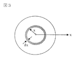
- FIG. 3 is a conceptual diagram showing contact conditions of metal fibers.
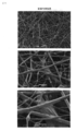
- FIG. 4 is an electron micrograph of the low resistance metal fiber sheet of Example 2 of the present invention before pressurization and heat treatment.
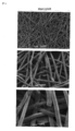
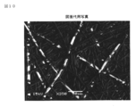
- FIG. 5 is an electron micrograph of the low resistance metal fiber sheet of Example 2 of the present invention after pressure and heat treatment.
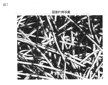
- FIG. 6 is an electron micrograph of a metal fiber sheet in which contact points of metal fibers are secured by sintering.
- FIG. 7 is an electron micrograph of the low resistance metal fiber sheet of Example 4 of the present invention after pressure and heat treatment.
- FIG. 8 is an electron micrograph of the low resistance metal fiber sheet of Example 5 of the present invention after pressure and heat treatment.
- FIG. 9 is an electron micrograph of the low resistance metal fiber sheet of Example 6 of the present invention after pressure and heat treatment.
- FIG. 10 is an electron micrograph of the low resistance metal fiber sheet of Example 7 of the present invention after pressure and heat treatment.
- FIG. 11 is an electron micrograph of the low resistance metal fiber sheet of Example 8 of the present invention after pressure and heat treatment.
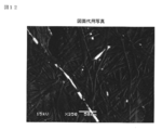
- FIG. 12 is an electron micrograph of the low resistance metal fiber sheet of Comparative Example 4 after pressure and heat treatment.
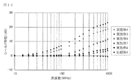
- FIG. 13 is a graph showing the electric field shielding characteristics before pressing and heating of the low resistance metal fiber sheets of Examples 4 to 8 and Comparative Example 4 of the present invention.
- FIG. 14 is a graph showing electric field shielding characteristics after pressing and heating of the low resistance metal fiber sheets of Examples 4 to 8 and Comparative Example 4 of the present invention.
- FIG. 15 is a graph showing the magnetic field shielding characteristics before pressing and heating of the low resistance metal fiber sheets of Examples 4 to 8 and Comparative Example 4 of the present invention.
- FIG. 16 is a graph showing the magnetic field shielding characteristics after pressurization and heating of the low resistance metal fiber sheets of Examples 4 to 8 and Comparative Example 4 of the present invention.
- the low resistance metal fiber sheet of the present invention comprises at least a metal fiber and a resin component.
- the resin component is melted at least partly, and the metal fiber is pressed so that at least part of the metal fibers are in contact with each other.
- the metal fiber content is 7% by volume or more and less than 75% by volume, and the resin component content is more than 25% by volume and is 93% by volume. It is essential that the volume is not more than%.
- the metal fibers have at least a contact point, and conductivity is obtained in the surface direction and the thickness direction of the low resistance metal fiber sheet. It means the state to be.
- the contact point of the metal fiber can be effectively secured and maintained, that is, a structure having portions where the metal fibers are in contact with each other is reliably formed. can do.
- the volume resistance value can be reduced to 10 ⁇ 2 ⁇ ⁇ cm or less.
- the low resistance metal fiber sheet of the present invention has a first embodiment in which the molten resin component forms a microporous film, and the metal fiber is bonded and fixed while the molten resin component leaves the fiber shape. And a second aspect of the configuration. As shown in FIG.
- the first aspect is that the metal fiber in a state where the resin component of the resin fiber is once melted and then pressed so that at least a part of the metal fibers are in contact with each other, It has a configuration in which a microporous membrane is formed along the metal fiber sheet surface while the molten resin component is bound and fixed.
- the second mode is such that at least a part of the metal fibers comes into contact after a part of the resin component is once melted while leaving the fiber shape of the resin fiber. It has a configuration in which a melted resin component is bonded and fixed to a pressed metal fiber.
- the low resistance metal fiber sheet of the present invention preferably has a basis weight of 10 to 1000 g / m 2 , more preferably 20 to 500 g / m 2 . If the basis weight is lower than 10 g / m 2 , the intended low resistance may not be exhibited, and the sheet strength may be too weak, which may hinder handling. On the other hand, when it exceeds 1000 g / m 2 , the flexibility as a sheet is impaired, and the economy may be lowered.
- the metal fiber used in the metal fiber sheet of the present invention include stainless steel fiber, copper fiber, aluminum fiber, nickel fiber, silver fiber, gold fiber, titanium fiber, etc.
- stainless steel fibers, copper fibers, and aluminum fibers are preferable.
- these metal fibers having a desired fiber length can be used, and metal fibers having different fiber lengths can be used together.
- the fiber diameter of these metal fibers is 5 to 50 ⁇ m, preferably 5 to 20 ⁇ m. If the fiber diameter is less than 5 ⁇ m, high processing accuracy is required, resulting in high manufacturing costs. On the other hand, when the fiber diameter exceeds 50 ⁇ m, the flexibility of the metal fiber sheet is lowered, and there are practical problems depending on applications.
- a natural resin, a synthetic resin, or the like can be used as the resin component in the present invention.
- a synthetic resin having thermoplasticity, heat melting property, and heat softening property is preferable, and a sheet is produced by a wet papermaking method.
- polyvinyl alcohol fiber, polyethylene fiber (PE fiber), polypropylene fiber, polyethylene terephthalate fiber (PET fiber), acrylic fiber, acrylic emulsion, nylon emulsion, polyethylene emulsion, NBR emulsion, SBR emulsion and the like are preferable.
- a powdery resin component such as PVA may be added.
- the manufacturing method of the low resistance metal fiber sheet of the present invention is a method for suitably manufacturing the low resistance metal fiber sheet of the present invention having the above-described configuration, and a sheet comprising at least metal fibers and resin fibers. It is essential to have a step of forming and a step of pressing and heat-treating the sheet between the supports.
- a wet papermaking method, a nonwoven fabric, a woven fabric production method, or the like can be used, but the porosity of the porous metal fiber sheet is precisely determined.
- At least the metal fiber and the resin It is preferable to have a step of obtaining a slurry by dispersing fibers in water and a step of making the slurry by a wet papermaking method.
- metal fibers and resin fibers cut to a desired length are disperse and dispersed in water, and if necessary, additives and the like are added, mixed, and then on the wire To obtain a pressing process and a drying process to produce a metal fiber sheet in which metal fibers and resin fibers are in contact with each other or entangled.
- a dispersant, a surfactant, an antifoaming agent, a paper strength agent, a sizing agent and the like that are generally used in wet papermaking can be used.
- the step of pressing and heat-treating the sheet between the supports is made of a metal with respect to the low resistance metal fiber sheet produced as described above. It is a step of heating at a temperature equal to or higher than the melting point of the resin component while being sandwiched between supports having excellent thermal conductivity such as a sheet and being pressurized in the thickness direction. Specifically, this step can be carried out by using a hot press, a thermal calendar, etc., and the pressure and temperature can be controlled as required, but the resin component is sufficiently melted and the metal fiber In order to make contact with each other more reliably, it is preferable to set a higher heating temperature with a slight margin than the melting point or softening temperature of the resin component.
- this support body can also be peeled from the low resistance metal fiber sheet after the following cooling or cooling.
- the low resistance metal fiber sheet of the present invention is allowed to cool or be cooled, so that the resin component is solidified and the state in which the contact between the metal fibers is maintained can be maintained.
- the low resistance metal fiber sheet of the present invention produced as described above is microporous by at least metal fibers and a resin component. By forming the micropores, the air resistance measured by the method according to JIS P8117 in the low-resistance metal fiber sheet of the present invention can be set to 100 seconds or less.
- the air resistance in the present invention indicates the air resistance according to the Gurley method, and is an index representing the air permeability of the test piece by the time required for 100 ml of air to pass through the test piece area of 6.42 cm 2 .
- the porosity indicating the degree of porosity of the metal fiber sheet is preferably 10 to 90%.
- the apparent density of the sheet is a value calculated from the basis weight and thickness of the sheet.
- the true density of the sheet is expressed by the following formula.
- True density of sheet 1 / ⁇ (0.01 ⁇ mixing ratio of metal fiber (wt%) / true density of metal fiber) + (0.01 ⁇ mixing ratio of resin component (wt%) / true density of resin component ) ⁇
- the porosity is less than 10%, the density of the low-resistance metal fiber sheet is increased, and the porosity may be reduced.
- the porosity exceeds 90%, the rigidity of the low-resistance metal fiber sheet itself may be reduced.
- the low resistance is realized by achieving good electrical contact between the metal fibers. The contact of this metal fiber is considered as follows.
- the metal fiber is a rigid fiber having a length of 1 having no thickness
- the number of contact of the fibers when m fibers per unit area are randomly scattered in a plane was calculated.
- the relationship between the fiber length l and the distance L between the fiber center points is important, and never contacts if l ⁇ L. That is, in order to make contact, it is necessary that the center point of another fiber exists within a range in which a circle having a radius of 1 is drawn from the center of one fiber as shown in FIG. In FIG. 1, a circle drawn with a diameter l represents a locus drawn when the fiber rotates with its center fixed, and two circles overlap is a necessary condition for contact.
- FIG. 3 depicts a circle having a radius l as in FIG. 1, but the center of the circle indicates the center point of one fiber. The distance between the center point of this fiber and the center point of another fiber existing in a circle having a radius l is represented by x. Then, the number of fibers present in the annular region should be 2 ⁇ mxdx, which is this area multiplied by m.
- Equation-8 represents the average probability that two fibers are in contact with each other in a circle with a radius of 1, but the combination of the number n of fibers present in a circle with a radius of l is n (n-1) / 2.
- Papermaking was performed by the method, followed by dehydration press and heat drying at 140 ° C. to obtain a fiber sheet having a basis weight of 50 g / m 2 .
- the obtained fiber sheet was heat calendered at a linear pressure of 150 kg / cm and a temperature of 110 ° C., and the low resistance metal fiber sheet of 32% by volume of stainless steel fiber and 68% by volume of polyethylene fiber of Example 1 of the present invention was obtained.
- Produced. ⁇ Example 2> A low resistance metal fiber sheet of Example 2 of the present invention was produced in the same manner as Example 1 except that the stainless steel fiber was 52% by volume and the polyethylene fiber was 48% by volume.
- Example 3> A low resistance metal fiber sheet of Example 3 of the present invention was produced in the same manner as Example 1 except that the stainless steel fiber was 7% by volume and the polyethylene fiber was 93% by volume.
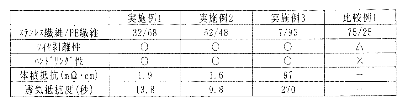
- Comparative Example 1> A low resistance metal fiber sheet of Comparative Example 1 of the present invention was produced in the same manner as in Example 1 except that 75% by volume of stainless steel fiber and 25% by volume of polyethylene fiber were used. 2. Evaluation With respect to the metal fiber sheets of Examples and Comparative Examples obtained as described above, wire peelability, handling property, volume resistance, and air resistance were evaluated according to the following methods. The evaluation results are shown in Table 1.
- Wire peelability In order to confirm the transferability of the paper sheet from the wire part to the downstream process, the wire peelability when transferring the paper sheet after dehydration press manually to the drying sheet during manual papermaking. confirmed. ⁇ : There is no problem in wire peelability (there is no paper sheet remaining on the wire sheet). ⁇ : Peeling from the wire sheet is possible (there is a slight peeling residue on the wire sheet). X: Peeling from the wire sheet is difficult. Handling property It was confirmed whether or not the paper strength required for, for example, the winding process after the paper sheet was dried. ⁇ : The paper strength was sufficient for handling after the drying step. (Triangle
- volume resistance The volume resistance of the metal fiber sheets obtained in Examples and Comparative Examples was determined by Loresta AXMCP-T370 according to a resistivity test method based on the four-probe method of JIS K7194 conductive plastic. Air permeability resistance By the method based on JIS P8117, the air resistance of the low resistance metal fiber sheet produced by the Example and the comparative example was measured. As is clear from Table 1, the low resistance metal fiber sheet of the present invention exhibited excellent characteristics in all evaluation items.
- Example 4 Production of Low Resistance Metal Fiber Sheet ⁇ Example 4> First, a slurry made of stainless steel fibers (material: SUS316L, trade name: BEKIPOR VG, manufactured by Bekaert) and polyethylene terephthalate fiber (trade name: Tepyrus TK08PN, manufactured by Teijin Ltd.) having a fiber diameter of 8 ⁇ m and a fiber length of 3 mm is manually prepared. Papermaking was performed by the method, followed by dehydration press and heat drying at 140 ° C. to obtain a fiber sheet having a basis weight of 50 g / m 2 .
- material material: SUS316L, trade name: BEKIPOR VG, manufactured by Bekaert
- polyethylene terephthalate fiber trade name: Tepyrus TK08PN, manufactured by Teijin Ltd.
- Example 5 The addition amount of stainless steel fiber and polyethylene terephthalate fiber was changed to make a low resistance metal fiber sheet of 40% by volume of stainless steel fiber and 60% by volume of polyethylene terephthalate fiber. The low resistance metal fiber sheet of Example 5 was produced.
- Example 6> The addition amount of the stainless steel fiber and the polyethylene terephthalate fiber was changed, and the low resistance metal fiber sheet of 15% by volume of the stainless steel fiber and 85% by volume of the polyethylene terephthalate fiber was used. The low resistance metal fiber sheet of Example 6 was produced.
- Example 7> The addition amount of stainless steel fiber and polyethylene terephthalate fiber was changed to a low resistance metal fiber sheet of 10 volume% stainless steel fiber and 90 volume% polyethylene terephthalate fiber. The low resistance metal fiber sheet of Example 7 was produced.
- Example 8> The addition amount of stainless steel fiber and polyethylene terephthalate fiber was changed, and the low resistance metal fiber sheet of 7% by volume of stainless steel fiber and 93% by volume of polyethylene terephthalate fiber was used. The low resistance metal fiber sheet of Example 8 was produced.
- FIGS. 13 and 14 are graphs showing electric field shielding characteristics before and after pressing and heating of the low-resistance metal fiber sheets of Examples 4 to 8 and Comparative Example 4, and FIGS. 15 and 16 show Examples 4 to 8 and It is a graph which shows the magnetic field shielding characteristic before and behind the pressurization and heating of the low resistance metal fiber sheet of Comparative Example 4.
- the electromagnetic shielding characteristics were evaluated in a 25 ° C. environment using the KEC method.
- the KEC method uses an electromagnetic shielding effect measuring device manufactured by the Kansai Electronics Industry Promotion Center, a measurement sample for electromagnetic wave intensity when nothing is sandwiched between jigs for radio waves and magnetic waves. This is a measurement method capable of measuring the attenuation of electromagnetic wave intensity when sandwiched between dB.
- As the frequency band measurement in the range of 10 to 1000 MHz was performed.
- Table 2 the low resistance metal fiber sheet of the present invention exhibited a good resistance to air permeability. Further, as is apparent from FIGS.
- the low resistance metal fiber sheet of the present invention exhibits excellent electromagnetic wave shielding characteristics after the heat calendar treatment.
- the resin components are too small to hold metal fibers in contact with each other. A metal fiber sheet that can withstand handling after papermaking could not be produced.
- the volume resistance value showed a high value because of the large amount of the resin component.
- the metal fiber sheet of Comparative Example 4 containing 2% by volume of metal fiber and 98% by volume of the resin component has a high volume resistance value, and it is shown that the electromagnetic wave shielding characteristics after the thermal calendar treatment are not sufficiently exhibited. It was. Furthermore, in the electromagnetic wave shielding characteristics before and after the heat calendering treatment of the low resistance metal fiber sheet of the present invention, different behaviors were shown depending on the contents of the metal fiber and the resin component. Specifically, in Examples 4 and 5 where the metal fiber content is as high as 40% by volume or more, it is surmised that the metal fiber contacts in the post-paper-making stage are poor, but the electromagnetic shielding properties before the heat calendering process are very high. Very low.
- the improvement of the electromagnetic wave shielding characteristics can be seen. Moreover, even if it is Example 7 and 8 with a low metal fiber content rate of 10 volume% or less, it is because a resin fiber fuse
Landscapes
- Chemical & Material Sciences (AREA)
- Inorganic Chemistry (AREA)
- Engineering & Computer Science (AREA)
- Microelectronics & Electronic Packaging (AREA)
- Paper (AREA)
- Shielding Devices Or Components To Electric Or Magnetic Fields (AREA)
- Inert Electrodes (AREA)
Abstract
簡便な方法により製造することができ、優れた多孔性及び低抵抗性を発揮することができる低抵抗金属繊維シートを提供する。少なくとも金属繊維と樹脂成分とからなる低抵抗金属繊維シートにおいて、樹脂成分は、少なくとも一部が溶融され、金属繊維は、金属繊維同士の少なくとも一部が接触するように圧着されつつ、溶融された樹脂成分を介して結着固定されており、金属繊維の含有率は、7体積%以上、75体積%未満であり、樹脂成分の含有率は、25体積%を越えて、93体積%以下である。
Description
本発明は、多孔性の金属繊維シートに係り、特に体積固有抵抗が非常に低い多孔性の低抵抗金属繊維シートに関するものである。
多孔性の金属繊維シートは、電磁波シールド材料や燃料電池用電極の構成部材等に広く検討されている。具体的には、電磁波シールド材料としては、金属繊維を含有する多孔性シートを焼結することにより、金属繊維の接触点を確保した電磁波シールド用シートが知られている(例えば特許文献1及び2参照。)。このような電磁波シールド用シートは、例えば金属繊維と樹脂繊維とを湿式抄紙法により抄造し、これを焼結することにより製造される。
また、燃料電池用電極の金属繊維シートとしては、導電性短繊維を含有した熱可塑性樹脂からなり、体積固有抵抗を1000Ω・cm以下とし、少なくとも片面に電極活性物質を付着させた電池電極用導電性シートが知られている(例えば特許文献3参照。)。この導電性シートにおいては、導電性短繊維の含有率を高めることにより、短繊維の接触点確率を上昇させて、体積固有抵抗を低減させている。
また、燃料電池用電極の金属繊維シートとしては、導電性短繊維を含有した熱可塑性樹脂からなり、体積固有抵抗を1000Ω・cm以下とし、少なくとも片面に電極活性物質を付着させた電池電極用導電性シートが知られている(例えば特許文献3参照。)。この導電性シートにおいては、導電性短繊維の含有率を高めることにより、短繊維の接触点確率を上昇させて、体積固有抵抗を低減させている。
しかしながら、上記の電磁波シールド用シートでは、金属繊維の焼結を真空中又は非酸化性雰囲気下で行う必要があり、製造コストが非常に高く、実用的ではないといった問題を有していた。
そこで、本発明は、上記のような状況に鑑みてなされたもので、簡便な方法により製造することができ、優れた多孔性及び低抵抗性を示す金属繊維シートを提供することを目的としている。
そこで、本発明は、上記のような状況に鑑みてなされたもので、簡便な方法により製造することができ、優れた多孔性及び低抵抗性を示す金属繊維シートを提供することを目的としている。
本発明者らは、上記課題を解決するために、複雑な工程及び高価な設備を必要とする焼結のような工程を用いることなく、金属繊維同士の接触点が有効に確保・維持された金属繊維シートの製造について鋭意検討を重ねた結果、特定の金属繊維と樹脂繊維からなるシートを形成し、このシートを加圧・加熱することにより、優れた多孔性及び低抵抗性を発揮する本願発明の低抵抗金属繊維シートを発明するに至った。したがって、本発明の低抵抗金属繊維シートは、少なくとも金属繊維と樹脂成分とからなり、上記樹脂成分は、少なくとも一部が溶融され、上記金属繊維は、金属繊維同士の少なくとも一部が接触するように圧着されつつ、溶融された上記樹脂成分を介して結着固定されており、上記金属繊維の含有率は、7体積%以上、75体積%未満であり、上記樹脂成分の含有率は、25体積%を越えて、93体積%以下であることを特徴としている。
また、本発明の低抵抗金属繊維シートにおいては、溶融された樹脂成分は、微多孔膜を形成していることが好ましく、或いは、繊維形状を残しつつも前記金属繊維同士を結着固定していることが好ましい。
さらに、本発明の低抵抗金属繊維シートにおいては、その用途により、体積抵抗値を変更することが可能ではあるが、体積抵抗値が10−2Ω・cm以下であることが好ましく、金属繊維は、ステンレス繊維、銅繊維、アルミニウム繊維から選ばれる少なくとも1種であり、樹脂成分は、合成樹脂であることが好ましい。また、本発明の金属繊維シートにおいては、少なくとも金属繊維と樹脂成分によって、微多孔が形成されていることが好ましく、JIS8117に準拠する方法により測定する透気抵抗度は100秒以下であることが好ましい。
また、本発明の低抵抗金属繊維シートの製造方法は、少なくとも金属繊維と樹脂繊維とからなるシートを形成する工程と、シートを支持体間に挟んで加圧、加熱処理する工程とを有することを特徴としている。また、本発明の低抵抗金属繊維シートの製造方法においては、少なくとも金属繊維と樹脂繊維とからなるシートを形成する工程は、少なくとも金属繊維と樹脂繊維とを水に分散してスラリーを得る工程と、該スラリーを湿式抄造法により抄造する工程とを有することが好ましい。
また、本発明の低抵抗金属繊維シートにおいては、溶融された樹脂成分は、微多孔膜を形成していることが好ましく、或いは、繊維形状を残しつつも前記金属繊維同士を結着固定していることが好ましい。
さらに、本発明の低抵抗金属繊維シートにおいては、その用途により、体積抵抗値を変更することが可能ではあるが、体積抵抗値が10−2Ω・cm以下であることが好ましく、金属繊維は、ステンレス繊維、銅繊維、アルミニウム繊維から選ばれる少なくとも1種であり、樹脂成分は、合成樹脂であることが好ましい。また、本発明の金属繊維シートにおいては、少なくとも金属繊維と樹脂成分によって、微多孔が形成されていることが好ましく、JIS8117に準拠する方法により測定する透気抵抗度は100秒以下であることが好ましい。
また、本発明の低抵抗金属繊維シートの製造方法は、少なくとも金属繊維と樹脂繊維とからなるシートを形成する工程と、シートを支持体間に挟んで加圧、加熱処理する工程とを有することを特徴としている。また、本発明の低抵抗金属繊維シートの製造方法においては、少なくとも金属繊維と樹脂繊維とからなるシートを形成する工程は、少なくとも金属繊維と樹脂繊維とを水に分散してスラリーを得る工程と、該スラリーを湿式抄造法により抄造する工程とを有することが好ましい。
本発明の低抵抗金属繊維シートによれば、簡便な方法により製造することが可能で、優れた多孔性及び低抵抗性を発揮することができる。
図1は、金属繊維の接触条件を示す概念図である。
図2は、金属繊維の接触条件を示す概念図である。
図3は、金属繊維の接触条件を示す概念図である。
図4は、本発明の実施例2の低抵抗金属繊維シートの加圧・加熱処理前の電子顕微鏡写真である。
図5は、本発明の実施例2の低抵抗金属繊維シートの加圧・加熱処理後の電子顕微鏡写真である。
図6は、焼結により金属繊維の接触点を確保した金属繊維シートの電子顕微鏡写真である。
図7は、本発明の実施例4の低抵抗金属繊維シートの加圧・加熱処理後の電子顕微鏡写真である。
図8は、本発明の実施例5の低抵抗金属繊維シートの加圧・加熱処理後の電子顕微鏡写真である。
図9は、本発明の実施例6の低抵抗金属繊維シートの加圧・加熱処理後の電子顕微鏡写真である。
図10は、本発明の実施例7の低抵抗金属繊維シートの加圧・加熱処理後の電子顕微鏡写真である。
図11は、本発明の実施例8の低抵抗金属繊維シートの加圧・加熱処理後の電子顕微鏡写真である。
図12は、比較例4の低抵抗金属繊維シートの加圧・加熱処理後の電子顕微鏡写真である。
図13は、本発明の実施例4~8及び比較例4の低抵抗金属繊維シートの加圧・加熱前の電界シールド特性を示すグラフである。
図14は、本発明の実施例4~8及び比較例4の低抵抗金属繊維シートの加圧・加熱後の電界シールド特性を示すグラフである。
図15は、本発明の実施例4~8及び比較例4の低抵抗金属繊維シートの加圧・加熱前の磁界シールド特性を示すグラフである。
図16は、本発明の実施例4~8及び比較例4の低抵抗金属繊維シートの加圧・加熱後の磁界シールド特性を示すグラフである。
図2は、金属繊維の接触条件を示す概念図である。
図3は、金属繊維の接触条件を示す概念図である。
図4は、本発明の実施例2の低抵抗金属繊維シートの加圧・加熱処理前の電子顕微鏡写真である。
図5は、本発明の実施例2の低抵抗金属繊維シートの加圧・加熱処理後の電子顕微鏡写真である。
図6は、焼結により金属繊維の接触点を確保した金属繊維シートの電子顕微鏡写真である。
図7は、本発明の実施例4の低抵抗金属繊維シートの加圧・加熱処理後の電子顕微鏡写真である。
図8は、本発明の実施例5の低抵抗金属繊維シートの加圧・加熱処理後の電子顕微鏡写真である。
図9は、本発明の実施例6の低抵抗金属繊維シートの加圧・加熱処理後の電子顕微鏡写真である。
図10は、本発明の実施例7の低抵抗金属繊維シートの加圧・加熱処理後の電子顕微鏡写真である。
図11は、本発明の実施例8の低抵抗金属繊維シートの加圧・加熱処理後の電子顕微鏡写真である。
図12は、比較例4の低抵抗金属繊維シートの加圧・加熱処理後の電子顕微鏡写真である。
図13は、本発明の実施例4~8及び比較例4の低抵抗金属繊維シートの加圧・加熱前の電界シールド特性を示すグラフである。
図14は、本発明の実施例4~8及び比較例4の低抵抗金属繊維シートの加圧・加熱後の電界シールド特性を示すグラフである。
図15は、本発明の実施例4~8及び比較例4の低抵抗金属繊維シートの加圧・加熱前の磁界シールド特性を示すグラフである。
図16は、本発明の実施例4~8及び比較例4の低抵抗金属繊維シートの加圧・加熱後の磁界シールド特性を示すグラフである。
以下、本発明のより好適な実施の形態について詳細に説明する。
本発明の低抵抗金属繊維シートは、少なくとも金属繊維と樹脂成分とからなり、樹脂成分は、少なくとも一部が溶融され、金属繊維は、金属繊維同士の少なくとも一部が接触するように圧着されつつ、溶融された樹脂成分を介して結着固定されており、金属繊維の含有率は、7体積%以上、75体積%未満であり、樹脂成分の含有率は、25体積%を越えて、93体積%以下であることが必須である。なお、本発明における金属繊維同士の少なくとも一部が接触するとは、金属繊維同士が少なくとも部分的に接触点を有し、低抵抗金属繊維シートの面方向、厚さ方向に渡って導電性が得られる状態を意味する。このように、金属繊維と樹脂成分の含有量を規定することにより、金属繊維の接触点を有効に確保・維持することができ、すなわち、金属繊維が互いに接触する部分を有する構造を確実に形成することができる。これにより、本発明の低抵抗金属繊維シートにおいては、体積抵抗値を10−2Ω・cm以下に低減することができる。金属繊維が75体積%以上、樹脂成分が25体積%以下であると、樹脂成分が、金属繊維の接触を充分に保持することができなくなり、体積固有抵抗が上昇してしまう。一方、金属繊維が7体積%未満であり、樹脂成分が93体積%を越えると、金属繊維の接触状態の形成が難くなるためであると推察されるが、この場合も体積固有抵抗が上昇してしまう。
本発明の低抵抗金属繊維シートは、溶融された樹脂成分が微多孔膜を形成している構成の第1態様と、溶融された樹脂成分が繊維形状を残しつつも金属繊維同士を結着固定している構成の第2態様とを含む。第1態様は、図5に示されたように、樹脂繊維の樹脂成分の大部分が一旦溶融された後、金属繊維同士の少なくとも一部が接触するように圧着された状態の金属繊維を、溶融された樹脂成分が結着固定しつつ、金属繊維シート面に沿って微多孔膜を形成した構成を有する。また、第2態様は、図7~11に示されたように、樹脂繊維の繊維形状を残しつつ樹脂成分の一部が一旦溶融された後、金属繊維同士の少なくとも一部が接触するように圧着された状態の金属繊維を、溶融された樹脂成分が結着固定した構成を有する。
また、本発明の低抵抗金属繊維シートは、坪量が10~1000g/m2であることが好ましく、更に好ましくは20~500g/m2である。10g/m2よりも坪量が低い場合には、目的とする低抵抗性を発揮できなくなる恐れがあり、かつシート強度が弱くなりすぎてハンドリングに支障をきたす恐れがある。一方、1000g/m2を超える場合には、シートとしての屈曲性が損なわれると共に、経済性が低下する恐れがある。
本発明の金属繊維シートに用いられる金属繊維としては、ステンレス繊維、銅繊維、アルミニウム繊維、ニッケル繊維、銀繊維、金繊維、チタン繊維等が挙げられるが、これらの中でも、固有抵抗値と経済性の観点から、ステンレス繊維、銅繊維、アルミニウム繊維が好ましい。
また、これらの金属繊維は、所望の繊維長のものを使用可能であり、繊維長が異なる金属繊維を併用することもできるが、湿式抄紙法によりシートを作製する場合には、地合構成の観点から0.5~20.0mmであることが好ましい。さらに、これらの金属繊維の繊維径は5~50μm、好ましくは5~20μmであることが好適である。この繊維径が5μm未満では、高い加工精度が要求されるため、製造コストが高くなってしまう。一方、繊維径が50μmを超えると、金属繊維シートの柔軟性が低くなり、用途によっては実用上問題を有することとなる。
本発明における樹脂成分としては、天然樹脂、合成樹脂等を用いることができるが、熱可塑性、熱溶融性、熱軟化性を有する合成樹脂であることが好ましく、湿式抄紙法によりシートを作製する場合には、ポリビニルアルコール繊維、ポリエチレン繊維(PE繊維)、ポリプロピレン繊維、ポリエチレンテフタレート繊維(PET繊維)、アクリル繊維、アクリルエマルジョン、ナイロンエマルジョン、ポリエチレンエマルジョン、NBRエマルジョン、SBRエマルジョン等であることが好ましい。また、繊維状の樹脂成分に加えて、例えば、PVA等の粉体状の樹脂成分を添加することも出来る。
また、本発明の低抵抗金属繊維シートの製造方法は、上記のような構成を有する本発明の低抵抗金属繊維シートを好適に製造する方法であり、少なくとも金属繊維と樹脂繊維とからなるシートを形成する工程と、シートを支持体間に挟んで加圧、加熱処理する工程とを有することを必須としている。本発明における少なくとも金属繊維と樹脂繊維とからなるシートを形成する工程は、湿式抄造法、不織布、織布の作製方法等を用いることができるが、多孔性の金属繊維シートの空隙率を精密に制御し、金属繊維と樹脂繊維の接触或いは、交絡を高度に達成し、後工程の加圧、加熱工程で金属繊維同士の接触をより確実にする必要がある場合には、少なくとも金属繊維と樹脂繊維とを水に分散してスラリーを得る工程と、該スラリーを湿式抄造法により抄造する工程とを有することが好ましい。
湿式抄造法による場合について、具体的に説明すると、所望の長さにカットされた金属繊維と樹脂繊維を水中に離解分散させ、必要に応じて助剤等を添加し、混合した後、ワイヤ上で脱水処理し、プレス工程、乾燥工程を得て、金属繊維と樹脂繊維が接触或いは、交絡した金属繊維シートを製造する。なお、助剤としては、一般に湿式抄造法に使用されている分散剤、界面活性剤、消泡剤、紙力剤、サイズ剤等が使用できる。
また、本発明の低抵抗金属繊維シートの製造方法における、シートを支持体間に挟んで加圧、加熱処理する工程は、上記のようにして製造された低抵抗金属繊維シートに対して、金属シート等の熱伝導性に優れた支持体間に挟み込んで厚さ方向に加圧しつつ樹脂成分の融点以上の温度で加熱する工程である。この工程は、具体的には、熱プレス、熱カレンダー等を用いることにより実施することができ、要求に応じて圧力及び温度を制御することができるが、樹脂成分が充分に溶融し、金属繊維同士の接触がより確実に成されるためには、樹脂成分の融点又は、軟化温度よりも、若干余裕を持って高めの加熱温度設定とすることが好ましい。なお、この支持体は、以下の放冷又は、冷却が済んだ後に低抵抗金属繊維シートから剥離することも出来る。
加圧・加熱工程後、本発明の低抵抗金属繊維シートは放冷又は、冷却されることによって、樹脂成分が固化し、金属繊維同士の接触が保持されたままの状態を維持することができる。
上記のようにして製造される本発明の低抵抗金属繊維シートは、少なくとも金属繊維と樹脂成分によって微多孔が形成される。この微多孔の形成により、本発明の低抵抗金属繊維シートにおける、JIS P8117に準拠する方法により測定される透気抵抗度を100秒以下とすることができる。本発明における透気抵抗度は、ガーレー法による透気抵抗度を示し、試験片面積6.42cm2を100mlの空気が通過する時間により、試験片の通気性を表す指標である。この透気度が300秒よりも長いと、通気性が悪化する傾向がある。
さらに、本発明の低抵抗金属繊維シートにおいては、金属繊維シートの多孔性の度合を示す空隙率が10~90%であることが好ましい。なお、本発明における空隙率は下記の式により定義される。
空隙率(%)={1−(シートの見掛けの密度/シートの真の密度)}×100
式中、シートの見掛けの密度は、シートの坪量と厚さから計算される値である。
シートの真の密度は、下記式で表される。
シートの真密度=1/{(0.01×金属繊維の配合比率(wt%)/金属繊維の真密度)+(0.01×樹脂成分の配合比率(wt%)/樹脂成分の真密度)}
この空隙率が10%未満であると、低抵抗金属繊維シートの密度が高くなり、多孔性が低下する恐れがある。一方、空隙率が90%を超えると、低抵抗金属繊維シート自体の剛性が低下する恐れがある。
上記のようにして製造された本発明の低抵抗金属繊維シートにおいては、金属繊維同士が良好に電気的接触を達成することによって低抵抗を実現している。この金属繊維の接触については以下のように考察される。金属繊維を、太さを有しない長さlの剛直な繊維と仮定し、単位面積当たりm本の繊維がランダムに平面状に散りばめられている場合の繊維の接触数を計算した。
まず、2本の繊維が平面内で接触する条件を考えてみる。繊維の長さlとその繊維の中心点間の距離Lとの関係が重要であり、l<Lの場合には決して接触することはない。すなわち、接触するためには少なくとも図1に示されたように1本の繊維の中心から半径lの円を描いた範囲内に他の繊維の中心点が存在することが必要である。図1においては、直径lの描く円は繊維がその中心を固定して回転した場合に描く軌跡を表わしており、2つの円が重なり合うことが接触の必要条件である。
しかしながら、l>Lの条件であっても、2本の繊維の配向方向により接触する場合としない場合とが出てくる。そこで、図2に示したような直径lの2つの円AとBの重なりを使って接触の確率を考えてみる。ここで、次の式が成立する。
l/2・cosθ=L/2 ⇒ cosθ=L/l (式−1)
これを変形すれば次の式が得られる。
θ=arccos(L/l) (式−2)
円Aが円Bと重なりを持つためには、図2において2θの角度範囲に繊維が配向している必要がある。角度θをラジアル単位で表わすと、円Aが円Bと重なりを持つための配向の確率は4θ/2π、すなわち2θ/πとなる。円Bについても同様であるため、2つの円が実質的に重なりを持つ確率p1は
p1=(2θ/π)2=4(θ/π)2 (式−3)
で表わされる。このp1として、例えば0.23等の数字が得られた場合、これは本来確率を示すものではあるが、ここでは接触数と解釈することも出来る。
式−2において、2本の繊維の中心間距離Lが分かればθを求めることが出来るが、個々のLは不明である。そこで、Lの平均値Laveを求めてみることにする。図3に示された半径lの円において、円の中心からxの距離に描いた円周上に厚さdxの細い円環領域を考えてみると、この円環領域の面積は2πxdxと表わされる。
なお、図3は図1と同じく半径lの円を描いているが、円の中心は1本の繊維の中心点を示す。この繊維の中心点と、半径lの円の中に存在する他の繊維の中心点との距離はxで表わされる。
そうすると、この円環状領域に存在する繊維の数はこの面積にmを掛けた2πmxdxになるはずである。更に、円の中心からこの円環状領域まで距離はxで表わされるため、これを乗じることで円の中心からxの距離にある円環状領域にある他の繊維の中心までの距離を足し合わせたものが得られる。従って、これを積分することで円の中にある全ての距離を合計したものが得られることになる。

半径lの円内に存在する繊維の数nは、面積にmを掛けると良いので、
n=πl2m (式−5)
となる。式−4を式−5で割ってやれば、2本の繊維の中心間距離の平均値Laveが得られることになる。
Lave=(2/3)πml3/πl2m=(2/3)l (式−6)
従ってこれを式−2,3に代入すると
θave=arccos(Lave/l)=arccos(2/3)=0.841 (式−7)
p1=4(θave/π)2=0.287 (式−8)
が得られることになる。
式−8は半径1の円内で2本の繊維が接触する平均確率を表わすものであるが、半径lの円内に存在する繊維数nのその組み合わせはn(n−1)/2となるため、式−8にこの組み合わせ数を乗じたものがこの円内の総接触数Pということになる。
P=p1・n(n−1)/2
=4(θave/π)2・n(n−1)/2
=0.287πl2m(l2m−1)/2
=0.45l2m(l2m−1) (式−9)
この式を見ると接触数を得られるのは下記条件を満たす場合である。
l2m>1 l2>1/m (式−10)
この不等号式の右辺は単位面積を繊維の本数mに分割した面積を示すものであり、これが繊維長を1辺とする正方形の面積よりも小さくなければならないことになる。この条件は図1からも明らかである。
本発明の低抵抗金属繊維シートは、少なくとも金属繊維と樹脂成分とからなり、樹脂成分は、少なくとも一部が溶融され、金属繊維は、金属繊維同士の少なくとも一部が接触するように圧着されつつ、溶融された樹脂成分を介して結着固定されており、金属繊維の含有率は、7体積%以上、75体積%未満であり、樹脂成分の含有率は、25体積%を越えて、93体積%以下であることが必須である。なお、本発明における金属繊維同士の少なくとも一部が接触するとは、金属繊維同士が少なくとも部分的に接触点を有し、低抵抗金属繊維シートの面方向、厚さ方向に渡って導電性が得られる状態を意味する。このように、金属繊維と樹脂成分の含有量を規定することにより、金属繊維の接触点を有効に確保・維持することができ、すなわち、金属繊維が互いに接触する部分を有する構造を確実に形成することができる。これにより、本発明の低抵抗金属繊維シートにおいては、体積抵抗値を10−2Ω・cm以下に低減することができる。金属繊維が75体積%以上、樹脂成分が25体積%以下であると、樹脂成分が、金属繊維の接触を充分に保持することができなくなり、体積固有抵抗が上昇してしまう。一方、金属繊維が7体積%未満であり、樹脂成分が93体積%を越えると、金属繊維の接触状態の形成が難くなるためであると推察されるが、この場合も体積固有抵抗が上昇してしまう。
本発明の低抵抗金属繊維シートは、溶融された樹脂成分が微多孔膜を形成している構成の第1態様と、溶融された樹脂成分が繊維形状を残しつつも金属繊維同士を結着固定している構成の第2態様とを含む。第1態様は、図5に示されたように、樹脂繊維の樹脂成分の大部分が一旦溶融された後、金属繊維同士の少なくとも一部が接触するように圧着された状態の金属繊維を、溶融された樹脂成分が結着固定しつつ、金属繊維シート面に沿って微多孔膜を形成した構成を有する。また、第2態様は、図7~11に示されたように、樹脂繊維の繊維形状を残しつつ樹脂成分の一部が一旦溶融された後、金属繊維同士の少なくとも一部が接触するように圧着された状態の金属繊維を、溶融された樹脂成分が結着固定した構成を有する。
また、本発明の低抵抗金属繊維シートは、坪量が10~1000g/m2であることが好ましく、更に好ましくは20~500g/m2である。10g/m2よりも坪量が低い場合には、目的とする低抵抗性を発揮できなくなる恐れがあり、かつシート強度が弱くなりすぎてハンドリングに支障をきたす恐れがある。一方、1000g/m2を超える場合には、シートとしての屈曲性が損なわれると共に、経済性が低下する恐れがある。
本発明の金属繊維シートに用いられる金属繊維としては、ステンレス繊維、銅繊維、アルミニウム繊維、ニッケル繊維、銀繊維、金繊維、チタン繊維等が挙げられるが、これらの中でも、固有抵抗値と経済性の観点から、ステンレス繊維、銅繊維、アルミニウム繊維が好ましい。
また、これらの金属繊維は、所望の繊維長のものを使用可能であり、繊維長が異なる金属繊維を併用することもできるが、湿式抄紙法によりシートを作製する場合には、地合構成の観点から0.5~20.0mmであることが好ましい。さらに、これらの金属繊維の繊維径は5~50μm、好ましくは5~20μmであることが好適である。この繊維径が5μm未満では、高い加工精度が要求されるため、製造コストが高くなってしまう。一方、繊維径が50μmを超えると、金属繊維シートの柔軟性が低くなり、用途によっては実用上問題を有することとなる。
本発明における樹脂成分としては、天然樹脂、合成樹脂等を用いることができるが、熱可塑性、熱溶融性、熱軟化性を有する合成樹脂であることが好ましく、湿式抄紙法によりシートを作製する場合には、ポリビニルアルコール繊維、ポリエチレン繊維(PE繊維)、ポリプロピレン繊維、ポリエチレンテフタレート繊維(PET繊維)、アクリル繊維、アクリルエマルジョン、ナイロンエマルジョン、ポリエチレンエマルジョン、NBRエマルジョン、SBRエマルジョン等であることが好ましい。また、繊維状の樹脂成分に加えて、例えば、PVA等の粉体状の樹脂成分を添加することも出来る。
また、本発明の低抵抗金属繊維シートの製造方法は、上記のような構成を有する本発明の低抵抗金属繊維シートを好適に製造する方法であり、少なくとも金属繊維と樹脂繊維とからなるシートを形成する工程と、シートを支持体間に挟んで加圧、加熱処理する工程とを有することを必須としている。本発明における少なくとも金属繊維と樹脂繊維とからなるシートを形成する工程は、湿式抄造法、不織布、織布の作製方法等を用いることができるが、多孔性の金属繊維シートの空隙率を精密に制御し、金属繊維と樹脂繊維の接触或いは、交絡を高度に達成し、後工程の加圧、加熱工程で金属繊維同士の接触をより確実にする必要がある場合には、少なくとも金属繊維と樹脂繊維とを水に分散してスラリーを得る工程と、該スラリーを湿式抄造法により抄造する工程とを有することが好ましい。
湿式抄造法による場合について、具体的に説明すると、所望の長さにカットされた金属繊維と樹脂繊維を水中に離解分散させ、必要に応じて助剤等を添加し、混合した後、ワイヤ上で脱水処理し、プレス工程、乾燥工程を得て、金属繊維と樹脂繊維が接触或いは、交絡した金属繊維シートを製造する。なお、助剤としては、一般に湿式抄造法に使用されている分散剤、界面活性剤、消泡剤、紙力剤、サイズ剤等が使用できる。
また、本発明の低抵抗金属繊維シートの製造方法における、シートを支持体間に挟んで加圧、加熱処理する工程は、上記のようにして製造された低抵抗金属繊維シートに対して、金属シート等の熱伝導性に優れた支持体間に挟み込んで厚さ方向に加圧しつつ樹脂成分の融点以上の温度で加熱する工程である。この工程は、具体的には、熱プレス、熱カレンダー等を用いることにより実施することができ、要求に応じて圧力及び温度を制御することができるが、樹脂成分が充分に溶融し、金属繊維同士の接触がより確実に成されるためには、樹脂成分の融点又は、軟化温度よりも、若干余裕を持って高めの加熱温度設定とすることが好ましい。なお、この支持体は、以下の放冷又は、冷却が済んだ後に低抵抗金属繊維シートから剥離することも出来る。
加圧・加熱工程後、本発明の低抵抗金属繊維シートは放冷又は、冷却されることによって、樹脂成分が固化し、金属繊維同士の接触が保持されたままの状態を維持することができる。
上記のようにして製造される本発明の低抵抗金属繊維シートは、少なくとも金属繊維と樹脂成分によって微多孔が形成される。この微多孔の形成により、本発明の低抵抗金属繊維シートにおける、JIS P8117に準拠する方法により測定される透気抵抗度を100秒以下とすることができる。本発明における透気抵抗度は、ガーレー法による透気抵抗度を示し、試験片面積6.42cm2を100mlの空気が通過する時間により、試験片の通気性を表す指標である。この透気度が300秒よりも長いと、通気性が悪化する傾向がある。
さらに、本発明の低抵抗金属繊維シートにおいては、金属繊維シートの多孔性の度合を示す空隙率が10~90%であることが好ましい。なお、本発明における空隙率は下記の式により定義される。
空隙率(%)={1−(シートの見掛けの密度/シートの真の密度)}×100
式中、シートの見掛けの密度は、シートの坪量と厚さから計算される値である。
シートの真の密度は、下記式で表される。
シートの真密度=1/{(0.01×金属繊維の配合比率(wt%)/金属繊維の真密度)+(0.01×樹脂成分の配合比率(wt%)/樹脂成分の真密度)}
この空隙率が10%未満であると、低抵抗金属繊維シートの密度が高くなり、多孔性が低下する恐れがある。一方、空隙率が90%を超えると、低抵抗金属繊維シート自体の剛性が低下する恐れがある。
上記のようにして製造された本発明の低抵抗金属繊維シートにおいては、金属繊維同士が良好に電気的接触を達成することによって低抵抗を実現している。この金属繊維の接触については以下のように考察される。金属繊維を、太さを有しない長さlの剛直な繊維と仮定し、単位面積当たりm本の繊維がランダムに平面状に散りばめられている場合の繊維の接触数を計算した。
まず、2本の繊維が平面内で接触する条件を考えてみる。繊維の長さlとその繊維の中心点間の距離Lとの関係が重要であり、l<Lの場合には決して接触することはない。すなわち、接触するためには少なくとも図1に示されたように1本の繊維の中心から半径lの円を描いた範囲内に他の繊維の中心点が存在することが必要である。図1においては、直径lの描く円は繊維がその中心を固定して回転した場合に描く軌跡を表わしており、2つの円が重なり合うことが接触の必要条件である。
しかしながら、l>Lの条件であっても、2本の繊維の配向方向により接触する場合としない場合とが出てくる。そこで、図2に示したような直径lの2つの円AとBの重なりを使って接触の確率を考えてみる。ここで、次の式が成立する。
l/2・cosθ=L/2 ⇒ cosθ=L/l (式−1)
これを変形すれば次の式が得られる。
θ=arccos(L/l) (式−2)
円Aが円Bと重なりを持つためには、図2において2θの角度範囲に繊維が配向している必要がある。角度θをラジアル単位で表わすと、円Aが円Bと重なりを持つための配向の確率は4θ/2π、すなわち2θ/πとなる。円Bについても同様であるため、2つの円が実質的に重なりを持つ確率p1は
p1=(2θ/π)2=4(θ/π)2 (式−3)
で表わされる。このp1として、例えば0.23等の数字が得られた場合、これは本来確率を示すものではあるが、ここでは接触数と解釈することも出来る。
式−2において、2本の繊維の中心間距離Lが分かればθを求めることが出来るが、個々のLは不明である。そこで、Lの平均値Laveを求めてみることにする。図3に示された半径lの円において、円の中心からxの距離に描いた円周上に厚さdxの細い円環領域を考えてみると、この円環領域の面積は2πxdxと表わされる。
なお、図3は図1と同じく半径lの円を描いているが、円の中心は1本の繊維の中心点を示す。この繊維の中心点と、半径lの円の中に存在する他の繊維の中心点との距離はxで表わされる。
そうすると、この円環状領域に存在する繊維の数はこの面積にmを掛けた2πmxdxになるはずである。更に、円の中心からこの円環状領域まで距離はxで表わされるため、これを乗じることで円の中心からxの距離にある円環状領域にある他の繊維の中心までの距離を足し合わせたものが得られる。従って、これを積分することで円の中にある全ての距離を合計したものが得られることになる。
n=πl2m (式−5)
となる。式−4を式−5で割ってやれば、2本の繊維の中心間距離の平均値Laveが得られることになる。
Lave=(2/3)πml3/πl2m=(2/3)l (式−6)
従ってこれを式−2,3に代入すると
θave=arccos(Lave/l)=arccos(2/3)=0.841 (式−7)
p1=4(θave/π)2=0.287 (式−8)
が得られることになる。
式−8は半径1の円内で2本の繊維が接触する平均確率を表わすものであるが、半径lの円内に存在する繊維数nのその組み合わせはn(n−1)/2となるため、式−8にこの組み合わせ数を乗じたものがこの円内の総接触数Pということになる。
P=p1・n(n−1)/2
=4(θave/π)2・n(n−1)/2
=0.287πl2m(l2m−1)/2
=0.45l2m(l2m−1) (式−9)
この式を見ると接触数を得られるのは下記条件を満たす場合である。
l2m>1 l2>1/m (式−10)
この不等号式の右辺は単位面積を繊維の本数mに分割した面積を示すものであり、これが繊維長を1辺とする正方形の面積よりも小さくなければならないことになる。この条件は図1からも明らかである。
以下、実施例によって、本発明の構成及び効果を具体的に説明するが、本発明はこれらに何ら限定されるものではない。
A.第1実施形態
まず、溶融された樹脂成分が微多孔膜を形成している構成の本発明の低抵抗金属繊維シートの第1実施形態について説明する。
1.低抵抗金属繊維シートの作製
<実施例1>
まず、繊維径8μm、繊維長3mmのステンレス鋼繊維(材質:SUS316L、商品名:BEKIPOR VG、ベカルト社製)及び、ポリエチレン繊維(商品名:SWP EST2、三井化学社製)からなるスラリーを、手漉き法によって抄造し、脱水プレス、140℃での加熱乾燥を行い、坪量50g/m2の繊維シートを得た。得られた繊維シートに対して、線圧150kg/cm、温度110℃で熱カレンダー処理を行い、本発明実施例1のステンレス鋼繊維32体積%、ポリエチレン繊維68体積%の低抵抗金属繊維シートを作製した。
<実施例2>
ステンレス鋼繊維を52体積%、ポリエチレン繊維を48体積%としたこと以外は、実施例1と同様にして本発明の実施例2の低抵抗金属繊維シートを作製した。
<実施例3>
ステンレス鋼繊維を7体積%、ポリエチレン繊維を93体積%としたこと以外は、実施例1と同様にして本発明の実施例3の低抵抗金属繊維シートを作製した。
<比較例1>
ステンレス鋼繊維を75体積%、ポリエチレン繊維を25体積%としたこと以外は、実施例1と同様にして本発明の比較例1の低抵抗金属繊維シートを作製した。
2.評価
上記のようにして得られた実施例及び比較例の金属繊維シートに対して、以下の方法にしたがって、ワイヤ剥離性、ハンドリング性、体積抵抗、並びに、透気抵抗度を評価した。これらの評価結果を表1に示した。
ワイヤ剥離性
ワイヤパートから、下流工程への抄造シートの受け渡し性を確認するため、手漉き抄造時に、脱水プレス後の抄造シートを手作業で、ワイヤシートから乾燥用シートに移す際のワイヤ剥離性を確認した。
○:ワイヤ剥離性に問題なし(ワイヤシートに抄造シートの残りがない)。
△:ワイヤシートからの剥離が可能(ワイヤシートに若干の剥離残りあり)。
×:ワイヤシートからの剥離が困難。
ハンドリング性
抄造シート乾燥後の、例えば巻取り工程等に必要な紙力を有しているかどうかの確認を実施した。
○:乾燥工程後のハンドリングに充分絶え得る紙力を有していた。
△:乾燥工程後のハンドリングに絶え得るレベルではあるが、若干紙力が弱かった。
×:紙力が弱く、乾燥工程後のハンドリングに耐え得ないレベルであった。
体積抵抗
実施例、比較例で得られた金属繊維シートをJIS K7194導電性プラスチックの四探針法による抵抗率試験方法に従い、ロレスタAXMCP−T370により体積抵抗を求めた。
透気抵抗度
JIS P8117に準拠する方法により、実施例、比較例で作製した低抵抗金属繊維シートの透気抵抗度を測定した。
表1から明らかなように、本発明の低抵抗金属繊維シートでは、全ての評価項目で優れた特性を示していた。これに対して、金属繊維が75体積%、樹脂成分が25体積%含まれた比較例1の金属繊維シートでは、樹脂成分が少なすぎて、金属繊維同士を接触状態で保持することができず、抄造後のハンドリングに絶え得る金属繊維シートの作製が出来なかった。
3.金属繊維シートの構造
上記のようにして製造された本発明の実施例2の低抵抗金属繊維シートについて、熱カレンダー処理前後の表面の100倍、400倍及び900倍の電子顕微鏡写真を図4及び5に示した。また、比較用として、実施例に用いたステンレス鋼繊維を焼結した従来技術の焼結金属繊維シートの表面の100倍、400倍及び900倍の電子顕微鏡写真を図6に示した。これらの電子顕微鏡写真からも明らかなように、本発明の低抵抗金属繊維シートにおいては、加圧、加熱処理によって、金属繊維が厚さ方向に押圧されて金属繊維同士の接触点が形成され、溶融された樹脂成分が固化することで、比較用の焼結金属繊維シートと同様に金属繊維同士の接触点が保持された状態を、より簡便な方法で実現できることが示された。
B.第2実施形態
次に、溶融された樹脂成分が繊維形状を残しつつも金属繊維同士を結着固定している構成の本発明の低抵抗金属繊維シートの第2実施形態について説明する。
1.低抵抗金属繊維シートの作製
<実施例4>
まず、繊維径8μm、繊維長3mmのステンレス鋼繊維(材質:SUS316L、商品名:BEKIPOR VG、ベカルト社製)及び、ポリエチレンテレフタレート繊維(商品名:テピルスTK08PN、帝人社製)からなるスラリーを、手漉き法によって抄造し、脱水プレス、140℃での加熱乾燥を行い、坪量50g/m2の繊維シートを得た。得られた繊維シートに対して、線圧150kg/cm、温度170℃で熱カレンダー処理を行い、本発明実施例1のステンレス鋼繊維60体積%、ポリエチレンテレフタレート繊維40体積%の低抵抗金属繊維シートを作製した。
<実施例5>
ステンレス鋼繊維及び、ポリエチレンテレフタレート繊維の添加量を変更し、ステンレス鋼繊維40体積%、ポリエチレンテレフタレート繊維60体積%の低抵抗金属繊維シートとしたこと以外は、実施例4と同様にして本発明の実施例5の低抵抗金属繊維シートを作製した。
<実施例6>
ステンレス鋼繊維及び、ポリエチレンテレフタレート繊維の添加量を変更し、ステンレス鋼繊維15体積%、ポリエチレンテレフタレート繊維85体積%の低抵抗金属繊維シートとしたこと以外は、実施例4と同様にして本発明の実施例6の低抵抗金属繊維シートを作製した。
<実施例7>
ステンレス鋼繊維及び、ポリエチレンテレフタレート繊維の添加量を変更し、ステンレス鋼繊維10体積%、ポリエチレンテレフタレート繊維90体積%の低抵抗金属繊維シートとしたこと以外は、実施例4と同様にして本発明の実施例7の低抵抗金属繊維シートを作製した。
<実施例8>
ステンレス鋼繊維及び、ポリエチレンテレフタレート繊維の添加量を変更し、ステンレス鋼繊維7体積%、ポリエチレンテレフタレート繊維93体積%の低抵抗金属繊維シートとしたこと以外は、実施例4と同様にして本発明の実施例8の低抵抗金属繊維シートを作製した。
<比較例2>
ステンレス鋼繊維及び、ポリエチレンテレフタレート繊維の添加量を変更し、ステンレス鋼繊維75体積%、ポリエチレンテレフタレート繊維25体積%の低抵抗金属繊維シートとしたこと以外は、実施例4と同様にして比較例2の金属繊維シートを作製した。
<比較例3>
ステンレス鋼繊維及び、ポリエチレンテレフタレート繊維の添加量を変更し、ステンレス鋼繊維6体積%、ポリエチレンテレフタレート繊維94体積%の低抵抗金属繊維シートとしたこと以外は、実施例4と同様にして比較例3の金属繊維シートを作製した。
<比較例4>
ステンレス鋼繊維及び、ポリエチレンテレフタレート繊維の添加量を変更し、ステンレス鋼繊維2体積%、ポリエチレンテレフタレート繊維98体積%の低抵抗金属繊維シートとしたこと以外は、実施例4と同様にして本発明の比較例4の低抵抗金属繊維シートを作製した。
2.評価
上記のようにして得られた実施例及び比較例の金属繊維シートに対して、第1実施形態と同様の方法にしたがって、ワイヤ剥離性、ハンドリング性、体積抵抗、並びに、透気抵抗度を評価した。これらの評価結果を表2に示した。

さらに、以下の方法にしたがって、電界シールド特性及び磁界シールド特性を測定し、これらの測定結果を図13~16に示した。なお、図13及び14は実施例4~8及び比較例4の低抵抗金属繊維シートの加圧・加熱前後の電界シールド特性を示すグラフであり、図15及び16は、実施例4~8及び比較例4の低抵抗金属繊維シートの加圧・加熱前後の磁界シールド特性を示すグラフである。
電磁波シールド特性の測定
電磁波シールド特性はKEC法を用いて25℃環境下において評価した。KEC法とは、一般社団法人関西電子工業振興センター製の電磁波シールド効果測定装置を用い、電波用・磁波用それぞれ専用の治具の間に、何もはさまない場合の電磁波強度に対する測定サンプルをはさんだ場合の電磁波強度の減衰量をdBで測定することができる測定方法である。周波数帯としては、10~1000MHzの範囲の測定を実施した。
表2から明らかなように、本発明の低抵抗金属繊維シートは、良好な透気抵抗度を示していた。また、図13~16から明らかなように、本発明の低抵抗金属繊維シートでは、熱カレンダー処理後に優れた電磁波シールド特性が発揮されることが示された。これに対して、金属繊維が75体積%、樹脂成分が25体積%含まれた比較例2の金属繊維シートでは、樹脂成分が少なすぎて、金属繊維同士を接触状態で保持することができず、抄造後のハンドリングに耐え得る金属繊維シートの作製が出来なかった。また、金属繊維が6体積%、樹脂成分が94体積%含まれた比較例3の金属繊維シートでは、樹脂成分が多いためか、体積抵抗値が高めの値を示した。更に、金属繊維が2体積%、樹脂成分が98体積%含まれた比較例4の金属繊維シートでは、体積抵抗値が高く、熱カレンダー処理後の電磁波シールド特性も十分に発揮されないことが示された。
さらに、本発明の低抵抗金属繊維シートの熱カレンダー処理前後の電磁波シールド特性においては、金属繊維と樹脂成分の含有率により異なる挙動が示された。詳細には、金属繊維の含有率が40体積%以上と高い実施例4及び5では、抄紙後段階における金属繊維の接点が乏しいためと推察されるが、熱カレンダー処理前の電磁波シールド特性が非常に低い。ところが、熱カレンダー処理を行うことにより金属繊維シート中の金属繊維の接点が確保されるためであると推察されるが、電磁波シールド特性の向上が見て取れる。また、金属繊維の含有率が10体積%以下と低い実施例7及び8であっても、熱カレンダー処理を行うことにより、樹脂繊維が溶融して金属繊維の接点が形成されるためであると推察されるが、特に電界シールド特性が向上する。電磁波は電界、磁界のサイクルで伝わるため、電界又は、磁界のシールド特性が優れていれば電磁波シールド特性は満足される。しかしながら、比較例4では、熱カレンダー処理を経る前の方が電界シールド特性に優れた結果となった。これに関しては、抄紙段階で若干生じていた金属繊維同士の接点が、熱カレンダー処理を実施することにより、接点へ溶融した樹脂繊維成分が流入することにより失われたものと推察される。
3.金属繊維シートの構造
上記のようにして製造された本発明の実施例4~8及び比較例4の低抵抗金属繊維シートについて、熱カレンダー処理後の表面の350倍の電子顕微鏡写真を図7~12に示した。これらの電子顕微鏡写真からも明らかなように、本発明の低抵抗金属繊維シートは、溶融された樹脂成分が繊維形状を残しつつも金属繊維同士を結着固定している構成であっても、優れた特性を発揮することが示された。
以上説明したように、本発明の低抵抗金属繊維シートによれば、加圧、加熱処理のような簡便な方法により、優れた多孔性を維持しながら、低抵抗性が発揮されることが示された。
A.第1実施形態
まず、溶融された樹脂成分が微多孔膜を形成している構成の本発明の低抵抗金属繊維シートの第1実施形態について説明する。
1.低抵抗金属繊維シートの作製
<実施例1>
まず、繊維径8μm、繊維長3mmのステンレス鋼繊維(材質:SUS316L、商品名:BEKIPOR VG、ベカルト社製)及び、ポリエチレン繊維(商品名:SWP EST2、三井化学社製)からなるスラリーを、手漉き法によって抄造し、脱水プレス、140℃での加熱乾燥を行い、坪量50g/m2の繊維シートを得た。得られた繊維シートに対して、線圧150kg/cm、温度110℃で熱カレンダー処理を行い、本発明実施例1のステンレス鋼繊維32体積%、ポリエチレン繊維68体積%の低抵抗金属繊維シートを作製した。
<実施例2>
ステンレス鋼繊維を52体積%、ポリエチレン繊維を48体積%としたこと以外は、実施例1と同様にして本発明の実施例2の低抵抗金属繊維シートを作製した。
<実施例3>
ステンレス鋼繊維を7体積%、ポリエチレン繊維を93体積%としたこと以外は、実施例1と同様にして本発明の実施例3の低抵抗金属繊維シートを作製した。
<比較例1>
ステンレス鋼繊維を75体積%、ポリエチレン繊維を25体積%としたこと以外は、実施例1と同様にして本発明の比較例1の低抵抗金属繊維シートを作製した。
2.評価
上記のようにして得られた実施例及び比較例の金属繊維シートに対して、以下の方法にしたがって、ワイヤ剥離性、ハンドリング性、体積抵抗、並びに、透気抵抗度を評価した。これらの評価結果を表1に示した。
ワイヤパートから、下流工程への抄造シートの受け渡し性を確認するため、手漉き抄造時に、脱水プレス後の抄造シートを手作業で、ワイヤシートから乾燥用シートに移す際のワイヤ剥離性を確認した。
○:ワイヤ剥離性に問題なし(ワイヤシートに抄造シートの残りがない)。
△:ワイヤシートからの剥離が可能(ワイヤシートに若干の剥離残りあり)。
×:ワイヤシートからの剥離が困難。
ハンドリング性
抄造シート乾燥後の、例えば巻取り工程等に必要な紙力を有しているかどうかの確認を実施した。
○:乾燥工程後のハンドリングに充分絶え得る紙力を有していた。
△:乾燥工程後のハンドリングに絶え得るレベルではあるが、若干紙力が弱かった。
×:紙力が弱く、乾燥工程後のハンドリングに耐え得ないレベルであった。
体積抵抗
実施例、比較例で得られた金属繊維シートをJIS K7194導電性プラスチックの四探針法による抵抗率試験方法に従い、ロレスタAXMCP−T370により体積抵抗を求めた。
透気抵抗度
JIS P8117に準拠する方法により、実施例、比較例で作製した低抵抗金属繊維シートの透気抵抗度を測定した。
表1から明らかなように、本発明の低抵抗金属繊維シートでは、全ての評価項目で優れた特性を示していた。これに対して、金属繊維が75体積%、樹脂成分が25体積%含まれた比較例1の金属繊維シートでは、樹脂成分が少なすぎて、金属繊維同士を接触状態で保持することができず、抄造後のハンドリングに絶え得る金属繊維シートの作製が出来なかった。
3.金属繊維シートの構造
上記のようにして製造された本発明の実施例2の低抵抗金属繊維シートについて、熱カレンダー処理前後の表面の100倍、400倍及び900倍の電子顕微鏡写真を図4及び5に示した。また、比較用として、実施例に用いたステンレス鋼繊維を焼結した従来技術の焼結金属繊維シートの表面の100倍、400倍及び900倍の電子顕微鏡写真を図6に示した。これらの電子顕微鏡写真からも明らかなように、本発明の低抵抗金属繊維シートにおいては、加圧、加熱処理によって、金属繊維が厚さ方向に押圧されて金属繊維同士の接触点が形成され、溶融された樹脂成分が固化することで、比較用の焼結金属繊維シートと同様に金属繊維同士の接触点が保持された状態を、より簡便な方法で実現できることが示された。
B.第2実施形態
次に、溶融された樹脂成分が繊維形状を残しつつも金属繊維同士を結着固定している構成の本発明の低抵抗金属繊維シートの第2実施形態について説明する。
1.低抵抗金属繊維シートの作製
<実施例4>
まず、繊維径8μm、繊維長3mmのステンレス鋼繊維(材質:SUS316L、商品名:BEKIPOR VG、ベカルト社製)及び、ポリエチレンテレフタレート繊維(商品名:テピルスTK08PN、帝人社製)からなるスラリーを、手漉き法によって抄造し、脱水プレス、140℃での加熱乾燥を行い、坪量50g/m2の繊維シートを得た。得られた繊維シートに対して、線圧150kg/cm、温度170℃で熱カレンダー処理を行い、本発明実施例1のステンレス鋼繊維60体積%、ポリエチレンテレフタレート繊維40体積%の低抵抗金属繊維シートを作製した。
<実施例5>
ステンレス鋼繊維及び、ポリエチレンテレフタレート繊維の添加量を変更し、ステンレス鋼繊維40体積%、ポリエチレンテレフタレート繊維60体積%の低抵抗金属繊維シートとしたこと以外は、実施例4と同様にして本発明の実施例5の低抵抗金属繊維シートを作製した。
<実施例6>
ステンレス鋼繊維及び、ポリエチレンテレフタレート繊維の添加量を変更し、ステンレス鋼繊維15体積%、ポリエチレンテレフタレート繊維85体積%の低抵抗金属繊維シートとしたこと以外は、実施例4と同様にして本発明の実施例6の低抵抗金属繊維シートを作製した。
<実施例7>
ステンレス鋼繊維及び、ポリエチレンテレフタレート繊維の添加量を変更し、ステンレス鋼繊維10体積%、ポリエチレンテレフタレート繊維90体積%の低抵抗金属繊維シートとしたこと以外は、実施例4と同様にして本発明の実施例7の低抵抗金属繊維シートを作製した。
<実施例8>
ステンレス鋼繊維及び、ポリエチレンテレフタレート繊維の添加量を変更し、ステンレス鋼繊維7体積%、ポリエチレンテレフタレート繊維93体積%の低抵抗金属繊維シートとしたこと以外は、実施例4と同様にして本発明の実施例8の低抵抗金属繊維シートを作製した。
<比較例2>
ステンレス鋼繊維及び、ポリエチレンテレフタレート繊維の添加量を変更し、ステンレス鋼繊維75体積%、ポリエチレンテレフタレート繊維25体積%の低抵抗金属繊維シートとしたこと以外は、実施例4と同様にして比較例2の金属繊維シートを作製した。
<比較例3>
ステンレス鋼繊維及び、ポリエチレンテレフタレート繊維の添加量を変更し、ステンレス鋼繊維6体積%、ポリエチレンテレフタレート繊維94体積%の低抵抗金属繊維シートとしたこと以外は、実施例4と同様にして比較例3の金属繊維シートを作製した。
<比較例4>
ステンレス鋼繊維及び、ポリエチレンテレフタレート繊維の添加量を変更し、ステンレス鋼繊維2体積%、ポリエチレンテレフタレート繊維98体積%の低抵抗金属繊維シートとしたこと以外は、実施例4と同様にして本発明の比較例4の低抵抗金属繊維シートを作製した。
2.評価
上記のようにして得られた実施例及び比較例の金属繊維シートに対して、第1実施形態と同様の方法にしたがって、ワイヤ剥離性、ハンドリング性、体積抵抗、並びに、透気抵抗度を評価した。これらの評価結果を表2に示した。
電磁波シールド特性の測定
電磁波シールド特性はKEC法を用いて25℃環境下において評価した。KEC法とは、一般社団法人関西電子工業振興センター製の電磁波シールド効果測定装置を用い、電波用・磁波用それぞれ専用の治具の間に、何もはさまない場合の電磁波強度に対する測定サンプルをはさんだ場合の電磁波強度の減衰量をdBで測定することができる測定方法である。周波数帯としては、10~1000MHzの範囲の測定を実施した。
表2から明らかなように、本発明の低抵抗金属繊維シートは、良好な透気抵抗度を示していた。また、図13~16から明らかなように、本発明の低抵抗金属繊維シートでは、熱カレンダー処理後に優れた電磁波シールド特性が発揮されることが示された。これに対して、金属繊維が75体積%、樹脂成分が25体積%含まれた比較例2の金属繊維シートでは、樹脂成分が少なすぎて、金属繊維同士を接触状態で保持することができず、抄造後のハンドリングに耐え得る金属繊維シートの作製が出来なかった。また、金属繊維が6体積%、樹脂成分が94体積%含まれた比較例3の金属繊維シートでは、樹脂成分が多いためか、体積抵抗値が高めの値を示した。更に、金属繊維が2体積%、樹脂成分が98体積%含まれた比較例4の金属繊維シートでは、体積抵抗値が高く、熱カレンダー処理後の電磁波シールド特性も十分に発揮されないことが示された。
さらに、本発明の低抵抗金属繊維シートの熱カレンダー処理前後の電磁波シールド特性においては、金属繊維と樹脂成分の含有率により異なる挙動が示された。詳細には、金属繊維の含有率が40体積%以上と高い実施例4及び5では、抄紙後段階における金属繊維の接点が乏しいためと推察されるが、熱カレンダー処理前の電磁波シールド特性が非常に低い。ところが、熱カレンダー処理を行うことにより金属繊維シート中の金属繊維の接点が確保されるためであると推察されるが、電磁波シールド特性の向上が見て取れる。また、金属繊維の含有率が10体積%以下と低い実施例7及び8であっても、熱カレンダー処理を行うことにより、樹脂繊維が溶融して金属繊維の接点が形成されるためであると推察されるが、特に電界シールド特性が向上する。電磁波は電界、磁界のサイクルで伝わるため、電界又は、磁界のシールド特性が優れていれば電磁波シールド特性は満足される。しかしながら、比較例4では、熱カレンダー処理を経る前の方が電界シールド特性に優れた結果となった。これに関しては、抄紙段階で若干生じていた金属繊維同士の接点が、熱カレンダー処理を実施することにより、接点へ溶融した樹脂繊維成分が流入することにより失われたものと推察される。
3.金属繊維シートの構造
上記のようにして製造された本発明の実施例4~8及び比較例4の低抵抗金属繊維シートについて、熱カレンダー処理後の表面の350倍の電子顕微鏡写真を図7~12に示した。これらの電子顕微鏡写真からも明らかなように、本発明の低抵抗金属繊維シートは、溶融された樹脂成分が繊維形状を残しつつも金属繊維同士を結着固定している構成であっても、優れた特性を発揮することが示された。
以上説明したように、本発明の低抵抗金属繊維シートによれば、加圧、加熱処理のような簡便な方法により、優れた多孔性を維持しながら、低抵抗性が発揮されることが示された。
Claims (8)
- 少なくとも金属繊維と樹脂成分とからなり、
上記樹脂成分は、少なくとも一部が溶融され、
上記金属繊維は、金属繊維同士の少なくとも一部が接触するように圧着されつつ、溶融された上記樹脂成分を介して結着固定されており、
上記金属繊維の含有率は、7体積%以上、75体積%未満であり、
上記樹脂成分の含有率は、25体積%を越えて、93体積%以下であることを特徴とする低抵抗金属繊維シート。 - 前記溶融された樹脂成分は、微多孔膜を形成していることを特徴とする請求項1に記載の低抵抗金属繊維シート。
- 前記溶融された樹脂成分は、繊維形状を残しつつも前記金属繊維同士を結着固定していることを特徴とする請求項1に記載の低抵抗金属繊維シート。
- 体積抵抗値は、10−2Ω・cm以下であることを特徴とする請求項1~3のいずれかに記載の低抵抗金属繊維シート。
- 前記金属繊維は、ステンレス繊維、銅繊維、アルミニウム繊維から選ばれる少なくとも1種であり、
前記樹脂成分は、合成樹脂であることを特徴とする請求項1~4のいずれかに記載の低抵抗金属繊維シート。 - 前記低抵抗金属繊維シートは、少なくとも金属繊維と樹脂成分によって、微細孔が形成されていることを特徴とする請求項1~5のいずれかに記載の低抵抗金属繊維シート。
- 少なくとも金属繊維と樹脂繊維とからなるシートを形成する工程と、
前記シートを支持体間に挟んで加圧、加熱処理する工程とを有することを特徴とする低抵抗金属繊維シートの製造方法。 - 前記少なくとも金属繊維と樹脂繊維とからなるシートを形成する工程は、
少なくとも金属繊維と樹脂繊維とを水に分散してスラリーを得る工程と、
該スラリーを湿式抄造法により抄造する工程とを有することを特徴とする請求項7に記載の低抵抗金属繊維シートの製造方法。
Priority Applications (1)
| Application Number | Priority Date | Filing Date | Title |
|---|---|---|---|
| JP2016555627A JP6590827B2 (ja) | 2015-03-31 | 2016-03-31 | 低抵抗金属繊維シート及びその製造方法 |
Applications Claiming Priority (2)
| Application Number | Priority Date | Filing Date | Title |
|---|---|---|---|
| JP2015-071512 | 2015-03-31 | ||
| JP2015071512 | 2015-03-31 |
Publications (1)
| Publication Number | Publication Date |
|---|---|
| WO2016159389A1 true WO2016159389A1 (ja) | 2016-10-06 |
Family
ID=57007264
Family Applications (1)
| Application Number | Title | Priority Date | Filing Date |
|---|---|---|---|
| PCT/JP2016/061329 Ceased WO2016159389A1 (ja) | 2015-03-31 | 2016-03-31 | 低抵抗金属繊維シート及びその製造方法 |
Country Status (2)
| Country | Link |
|---|---|
| JP (1) | JP6590827B2 (ja) |
| WO (1) | WO2016159389A1 (ja) |
Cited By (1)
| Publication number | Priority date | Publication date | Assignee | Title |
|---|---|---|---|---|
| CN110114915A (zh) * | 2016-12-22 | 2019-08-09 | I&T新材料株式会社 | 蓄电装置的电极及其制造方法 |
Citations (9)
| Publication number | Priority date | Publication date | Assignee | Title |
|---|---|---|---|---|
| JPS49109603A (ja) * | 1973-02-23 | 1974-10-18 | ||
| JPS61225398A (ja) * | 1985-03-28 | 1986-10-07 | 愛媛県 | 導電繊維含有シ−ト状組成物 |
| JPS61289200A (ja) * | 1985-06-11 | 1986-12-19 | アイシン精機株式会社 | 金属繊維シ−トの製造方法 |
| JPS62251137A (ja) * | 1986-04-24 | 1987-10-31 | 三菱レイヨン株式会社 | 袋物用磁気シ−ルド性裏地材 |
| JPH03246999A (ja) * | 1990-02-23 | 1991-11-05 | Michio Arai | 電磁波シールド用シート材料 |
| JPH05295691A (ja) * | 1992-04-17 | 1993-11-09 | Tomoegawa Paper Co Ltd | 導電性フッ素繊維紙及びその製造方法 |
| JP2000154491A (ja) * | 1998-11-18 | 2000-06-06 | Tomoegawa Paper Co Ltd | 耐熱性紙状物及びその製造方法 |
| JP2000216583A (ja) * | 1999-01-22 | 2000-08-04 | Tomoegawa Paper Co Ltd | 機器・システム用電線・ケ―ブルの電磁波シ―ルドテ―プ |
| US20040142620A1 (en) * | 2002-09-10 | 2004-07-22 | Fibermark, Inc. | Nonwoven fiber webs with poly(phenylene sulfide) binder |
Family Cites Families (1)
| Publication number | Priority date | Publication date | Assignee | Title |
|---|---|---|---|---|
| JP2013241690A (ja) * | 2012-05-18 | 2013-12-05 | Mitsubishi Paper Mills Ltd | 不織布 |
-
2016
- 2016-03-31 WO PCT/JP2016/061329 patent/WO2016159389A1/ja not_active Ceased
- 2016-03-31 JP JP2016555627A patent/JP6590827B2/ja active Active
Patent Citations (9)
| Publication number | Priority date | Publication date | Assignee | Title |
|---|---|---|---|---|
| JPS49109603A (ja) * | 1973-02-23 | 1974-10-18 | ||
| JPS61225398A (ja) * | 1985-03-28 | 1986-10-07 | 愛媛県 | 導電繊維含有シ−ト状組成物 |
| JPS61289200A (ja) * | 1985-06-11 | 1986-12-19 | アイシン精機株式会社 | 金属繊維シ−トの製造方法 |
| JPS62251137A (ja) * | 1986-04-24 | 1987-10-31 | 三菱レイヨン株式会社 | 袋物用磁気シ−ルド性裏地材 |
| JPH03246999A (ja) * | 1990-02-23 | 1991-11-05 | Michio Arai | 電磁波シールド用シート材料 |
| JPH05295691A (ja) * | 1992-04-17 | 1993-11-09 | Tomoegawa Paper Co Ltd | 導電性フッ素繊維紙及びその製造方法 |
| JP2000154491A (ja) * | 1998-11-18 | 2000-06-06 | Tomoegawa Paper Co Ltd | 耐熱性紙状物及びその製造方法 |
| JP2000216583A (ja) * | 1999-01-22 | 2000-08-04 | Tomoegawa Paper Co Ltd | 機器・システム用電線・ケ―ブルの電磁波シ―ルドテ―プ |
| US20040142620A1 (en) * | 2002-09-10 | 2004-07-22 | Fibermark, Inc. | Nonwoven fiber webs with poly(phenylene sulfide) binder |
Cited By (1)
| Publication number | Priority date | Publication date | Assignee | Title |
|---|---|---|---|---|
| CN110114915A (zh) * | 2016-12-22 | 2019-08-09 | I&T新材料株式会社 | 蓄电装置的电极及其制造方法 |
Also Published As
| Publication number | Publication date |
|---|---|
| JPWO2016159389A1 (ja) | 2018-01-25 |
| JP6590827B2 (ja) | 2019-10-16 |
Similar Documents
| Publication | Publication Date | Title |
|---|---|---|
| Wang et al. | Effective fabrication of flexible nickel chains/acrylate composite pressure-sensitive adhesives with layered structure for tunable electromagnetic interference shielding | |
| TWI613955B (zh) | 複合電磁波吸收薄片 | |
| Tang et al. | A carbon-fabric/polycarbonate sandwiched film with high tensile and EMI shielding comprehensive properties: An experimental study | |
| JP6166117B2 (ja) | 金属と炭素繊維との複合材の製造方法 | |
| Luo et al. | High‐performance, multifunctional, and designable carbon fiber felt skeleton epoxy resin composites EP/CF‐(CNT/AgBNs) x for thermal conductivity and electromagnetic interference shielding | |
| JPH0462042A (ja) | 複合ガスケット材料 | |
| TW201802167A (zh) | 絕緣樹脂材料、使用其之附金屬層之絕緣樹脂材料及電路基板 | |
| JPWO2015076387A1 (ja) | ノイズ吸収シート | |
| JP2019053010A (ja) | シートセンサ | |
| JP2017157671A (ja) | 有機ntc素子 | |
| TWI786278B (zh) | 電磁波吸收片及其製造方法 | |
| JP6590827B2 (ja) | 低抵抗金属繊維シート及びその製造方法 | |
| US20150280207A1 (en) | Method of preparing graphene-graphene fused material and method of preparing graphene-substrate composite using the same | |
| JP7571040B2 (ja) | 板状の複合材料 | |
| KR20200016230A (ko) | 폴리테트라플루오로에틸렌 및 충전제를 함유하는 판형의 복합 재료 | |
| Huang et al. | Dispersion of magnetic metals on expanded graphite for the shielding of electromagnetic radiations | |
| JPH05230799A (ja) | 金属繊維焼結シートおよびその製造方法 | |
| JP3614396B2 (ja) | ふっ素樹脂基板をミリメートル波帯域通信に使用する方法及びミリメートル波帯域通信用のふっ素樹脂基板 | |
| CN110602934A (zh) | 电磁屏蔽散热膜及其制备方法和应用 | |
| JP7275539B2 (ja) | 導電性金属樹脂積層体及びその成形体 | |
| KR20210062811A (ko) | 고전도성 탄소섬유 종이의 제조방법, 이에 따라 제조된 탄소섬유 종이 및 탄소섬유 종이를 포함하는 탄소섬유 면상발열체 | |
| Kim et al. | A study of the pressureless sintering process of silver nanoparticles for electromagnetic interference shielding applications | |
| CN213680494U (zh) | 一种黏附式电磁屏蔽膜 | |
| JP6462486B2 (ja) | 導電性合成紙 | |
| TWI605749B (zh) | 電磁干擾屏蔽膜 |
Legal Events
| Date | Code | Title | Description |
|---|---|---|---|
| ENP | Entry into the national phase |
Ref document number: 2016555627 Country of ref document: JP Kind code of ref document: A |
|
| 121 | Ep: the epo has been informed by wipo that ep was designated in this application |
Ref document number: 16773268 Country of ref document: EP Kind code of ref document: A1 |
|
| NENP | Non-entry into the national phase |
Ref country code: DE |
|
| 122 | Ep: pct application non-entry in european phase |
Ref document number: 16773268 Country of ref document: EP Kind code of ref document: A1 |