WO2016158586A1 - ホイールナット緩み検出用のセンサユニット、およびこれを備えた装置 - Google Patents
ホイールナット緩み検出用のセンサユニット、およびこれを備えた装置 Download PDFInfo
- Publication number
- WO2016158586A1 WO2016158586A1 PCT/JP2016/059059 JP2016059059W WO2016158586A1 WO 2016158586 A1 WO2016158586 A1 WO 2016158586A1 JP 2016059059 W JP2016059059 W JP 2016059059W WO 2016158586 A1 WO2016158586 A1 WO 2016158586A1
- Authority
- WO
- WIPO (PCT)
- Prior art keywords
- sensor unit
- wheel
- sensor
- spacer
- hub
- Prior art date
- Legal status (The legal status is an assumption and is not a legal conclusion. Google has not performed a legal analysis and makes no representation as to the accuracy of the status listed.)
- Ceased
Links
Images







Classifications
-
- G—PHYSICS
- G01—MEASURING; TESTING
- G01L—MEASURING FORCE, STRESS, TORQUE, WORK, MECHANICAL POWER, MECHANICAL EFFICIENCY, OR FLUID PRESSURE
- G01L5/00—Apparatus for, or methods of, measuring force, work, mechanical power, or torque, specially adapted for specific purposes
- G01L5/24—Apparatus for, or methods of, measuring force, work, mechanical power, or torque, specially adapted for specific purposes for determining value of torque or twisting moment for tightening a nut or other member which is similarly stressed
Definitions
- the present invention relates to a wheel nut looseness detecting device for detecting looseness of a wheel nut in a fastening portion between a hub and a wheel used in a power transmission system of automobiles and various industrial machines, and a sensor unit for detecting the looseness.
- the appearance check after tightening the nut, indicate the circumferential phase between the nut and the wheel with a paint marker, or attach a cap that understands the circumferential phase to the nut to make it easier to detect the circumferential phase shift due to looseness.
- the hammering check is generally based on the inspector's empirical rules, but there are also diagnostic tools that incorporate an accelerometer into the hammering device to detect changes in the resonance frequency due to nut loosening or bolt damage. Exists.
- the device for detecting the acting force of the tire includes an elastic body having a columnar portion and a plate-like portion between a wheel support portion (hub) and a wheel, and the tire contact is determined from information such as stress and strain generated in each portion. Calculate and detect the acting force on the ground.
- This device is provided with a stress concentrating portion that increases the strain in the plate-like portion, but the specific proposal is not described in the patent document.
- Japanese Patent No. 4860680 Japanese Patent No. 5455357 Japanese Patent No. 5083314
- the method and apparatus for confirming the fastening state described above have the following problems.
- An object of the present invention is to detect a wheel nut looseness that can detect an abnormality such as looseness of a wheel nut during operation such as traveling, has excellent detection accuracy, has a simple structure, and has little influence on the support rigidity of the wheel. To provide a sensor unit for detecting the looseness.
- the sensor unit for detecting the loosening of the wheel nut is provided over the entire circumference of the hub, and between the heads of the plurality of hub bolts for attaching the wheel to the hub and the corresponding wheel nuts.
- the ring-shaped spacer member is interposed between the heads of the plurality of hub bolts arranged in the circumferential direction and the corresponding wheel nuts.
- the spacer-like member is distorted at the circumferential phase portion between the two bolt holes due to the difference in tightening force with other wheel nuts. This distortion is detected by the distortion sensor, and abnormality can be determined from the detected data.
- the spacer member for causing distortion is a ring-shaped member interposed between the head of the hub bolt and the wheel nut, and a structure in which a strain sensor is attached to the spacer member has a structure. Is simple and has little effect on the support rigidity of the wheel.
- the sensor unit only needs to be interposed between the head of the hub bolt and the wheel nut.
- the sensor unit may be disposed between the hub and the wheel, between the double wheel and between the wheel and the nut. .
- a recess and / or a lacking portion may be formed in a region other than the region within the outermost diameter of the plurality of wheel nuts.
- the spacer-like member includes a power supply for energizing the strain sensor and the communication device, and a communication device that communicates a detection signal of the strain sensor at a circumferential phase portion between the at least two bolt holes. It may be provided.
- a communication device and a power source are required, but by arranging the communication device and the power source in the circumferential phase portion between the bolt holes of the spacer-like member,
- the sensor unit can be configured compactly.
- the spacer-like member needs a certain thickness for tightening at the circumferential phase portion where the bolt holes are present, but the circumferential phase portion between the two bolt holes may be thin. Therefore, for example, by arranging the communication device and the power source in the space generated by the thinning, the communication device and the power source can be arranged without increasing the overall thickness of the sensor unit.
- the circumferential phase portion between the at least two bolt holes of the spacer member may be a thin portion.
- a thin portion By providing such a thin portion, it can be used as a mounting part for a sensor, a communication device, a power supply, etc., and the mounted sensor can be prevented from protruding from the entire thickness of the spacer member. Therefore, the spacer member can be sandwiched between the members without hindrance.
- strain can be concentrated, the sensitivity of a distortion detection can be improved, and the precision of the abnormality determination of a fastening state can be improved.
- the spacer member may have a thinnest portion serving as a strain concentration portion in a part of the circumferential phase portion that is the thin portion between the at least two bolt holes.
- the at least one strain sensor may be composed of a diaphragm attached to the spacer member and distorted by deformation of the spacer member, and a sensor element attached to the diaphragm and detecting the distortion of the diaphragm. . Rather than providing a thin portion on the spacer-like member itself, even if the diaphragm is provided as described above, the distortion of the spacer-like member can be detected with high sensitivity.
- the sensor unit may further include a temperature sensor that detects temperature and an acceleration sensor that detects acceleration. Since the detection value of the strain of the strain sensor varies depending on the temperature, it is preferable to detect the temperature by the temperature sensor and perform temperature correction in order to improve the accuracy of the fastening state abnormality determination.
- the temperature sensor can also detect abnormal heat generation due to brake dragging.
- the acceleration sensor can also detect damage to the hub bearing and abnormalities such as tire punctures.
- the sensor unit may further include wireless communication means for performing wireless communication for transmitting detection data of the strain sensor. Since the sensor unit rotates together with the wheel, a sliding part such as a slip ring is required for wired wiring. Therefore, it is preferable to use wireless communication.
- wireless communication means short-range wireless communication means of various standards can be adopted.
- a wheel nut loosening detection device includes the sensor unit and a fastening state determination unit that determines an abnormality in a fastening state of the wheel nut according to a predetermined reference from detection data of the at least one strain sensor.
- the “predetermined standard” may be an arbitrarily defined standard.
- the fastening state determination means determines the abnormality of the fastening state according to a predetermined standard from the distortion detection data, the detection accuracy is excellent.
- the fastening state determination unit can arbitrarily set the frequency of determining the abnormality and can determine during the traveling of the vehicle including the wheel. Since the usage pattern of the vehicle or the like in which the wheel is used varies greatly depending on the user or the like, it is convenient to use the abnormality determination at a frequency corresponding to the usage pattern. Further, if the determination can be made during traveling, it becomes possible to detect loosening of the nut that has occurred during traveling.
- FIG. 2 is a cutaway perspective view showing a mounting portion of a sensor unit of a wheel assembly in the wheel nut loosening detection device of FIG. 1.
- FIG. 1 It is a fragmentary perspective view which shows the 3rd example of the form of the thin part in the sensor unit of FIG. 2 from the front side and a back side.
- FIG. 1 It is a block diagram of a conceptual structure of the wheel nut loosening detection apparatus of FIG. It is a figure which shows the flow of operation
- FIG. 1 shows an entire system in which the wheel nut loosening detection device S according to the first embodiment is adopted in a large commercial vehicle.
- the wheel nut looseness detection device S is a fastening state determination provided in the spacer type sensor unit 3 mounted on the wheel portion of the wheel assembly 2A of the vehicle 1 and the information processing device 4 such as the vehicle-mounted device 4A or the portable terminal 4B.
- the information processing device 4 such as the vehicle-mounted device 4A or the portable terminal 4B.
- And means 5 In FIG. 1, a vehicle 1 is a truck that is a large commercial vehicle.
- the vehicle-mounted device 4A may be able to read information from an ECU (electric control unit) mounted on the vehicle 1.
- ECU electric control unit
- the mobile terminal 4B is a mobile phone such as a so-called smart phone having an information processing function, or a terminal dedicated to maintenance including portability-free locking detection or other maintenance applications.
- the fastening state determination unit 5 may be provided in any one of the information processing devices 4, but a plurality of information processing devices 4 such as the vehicle-mounted device 4 ⁇ / b> A and the portable terminal 4 ⁇ / b> B having the fastening state determination unit 5 may be provided.
- the said fastening state determination means 5 may be provided in information processing apparatuses, such as a server (not shown) connected to the said onboard equipment 4A and the portable terminal 4B via a wide area network.
- FIG. 2 is a cross-sectional view showing the sensor unit 3 mounted on a rear axle double wheel when the vehicle 1 is a large commercial vehicle, cut along a plane passing through the rotation axis. .
- the wheel assembly 2A two wheels 2 and 2 are stacked on one side of the flange 6a of the hub 6 so as to face each other, and a brake drum 9 is stacked on the other side of the flange 6a. These wheels 2 and 2 and the brake drum 9 are clamped and fixed between the head 7 a of the hub bolt 7 and the wheel nut 8.
- the hub bolts 7 are provided at a plurality of locations in the circumferential direction of the hub 6 and are inserted through bolt holes provided in the flange 6 a, the wheels 2, 2, and the brake drum 9.
- the hub 6 is installed on the outer periphery of an axle (not shown), but even if it is a part that constitutes a part of a hub bearing (that is, a wheel bearing), the part is provided separately from the hub bearing. It may be.
- a tire 10 is provided on the outer periphery of each wheel 2, 2, and the wheel 2 and the tire 10 constitute a wheel assembly 2 ⁇ / b> A.
- the sensor unit 3 is a circular ring-shaped and plate-like component concentric with the wheel 2.
- the sensor unit 3 is positioned between the two wheels 2, 2, and the head 7 a of each hub bolt 7 and the wheel nut 8. It is interposed between the hub bolt 7 and the wheel nut 8.
- the sensor unit 3 has bolt holes 11 (FIG. 1) at a plurality of locations in the circumferential direction, and hub bolts 7 are inserted through these bolt holes 11.
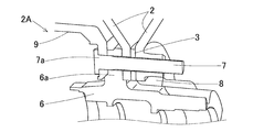
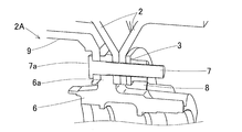
- FIG. 3A to 3C are enlarged views of the tightening portion of the sensor unit 3 in FIG. 2 by the wheel nut 8.
- the sensor unit 3 may be disposed between the two wheels 2 and 2 as in the first mounting example of FIG. 3A. Instead, it may be disposed between the wheel 2 and the wheel nut 8 as in the second mounting example of FIG. 3B. Further alternatively, it may be disposed between the flange 6a of the hub 6 and the wheel 2 as in the second mounting example of FIG. 3C.
- the sensor unit 3 is between the head 7 a of the hub bolt 7 and the wheel nut 8, it is between the flange 6 a of the hub 6 and the brake drum 9, or between the brake drum 9 and the head 7 a of the hub bolt 7.
- the hub bolt 7 may be disposed between the head 7a of the hub bolt 7 and the flange 6a of the hub 6.
- 6 is preferably arranged closer to the wheel nut 8 than the flange 6a.
- the spacer type sensor unit 3 is disposed in the rear wheel double wheel portion.
- the wheel assembly to which the wheel nut looseness detecting device is applied is a front tire single tire specification. May be.
- FIG. 4 shows the sensor unit 3 according to this embodiment.
- the sensor unit 3 includes a ring-like plate-like spacer member 12 and one or a plurality of strain sensors 13 attached to the spacer member 12.
- the strain sensor 13 is, for example, a foil strain gauge, a line strain gauge, or a semiconductor strain gauge.
- a temperature sensor 14 and an acceleration sensor 15 are attached to the spacer member 12 as a state detection sensor 21 that detects the state of the wheel 2.
- a gyroscope and a rotation sensor both not shown
- the state detection sensor 21 is a generic name for the sensors.
- the spacer member 12 is provided with a communication device 16 and a power source 17.
- a power source / communication unit 18 is used in which the communication device 16 and the power source 17 are combined into one component.
- the spacer-like member 12 is a member for causing deformation due to a difference in tightening force between the hub bolt 7 and the wheel nut 8 at each part of the hub. As described above, the bolt hole 11 through which each hub bolt 7 is inserted is provided. It has been.
- the material of the spacer-like member 12 may be formed of a metal material having high strength and rigidity such as an iron alloy, or may be formed of a metal material having relatively high elasticity such as an aluminum alloy. .
- the spacer member 12 has a thick portion 12a described later.
- the spacer-like member 12 has a shape in which neither a dent nor a missing portion exists in a region within the outermost diameter of the wheel nut 8, and this region is constituted by a thick portion 12 a. By adopting this shape, it is possible to connect firmly without impairing the axial force applied to the member related to the fastening of the wheel 2 by fastening the wheel nut 8.
- the wheel nut 8 has a washer part (not shown) integrally, the said outermost diameter is an outermost diameter containing the said washer part.
- the spacer member 12 further has a thin portion 12b.
- the phase portion where the bolt hole 11 exists, that is, the portion around the bolt hole 11 is the thick portion 12a, whereas the phase portion between the bolt holes 11 is the thin portion 12b.
- the thin-walled portion 12b has a shape in which only one main surface of the spacer-shaped member 12 is recessed from the thick-walled portion 12a even if both main surfaces of the spacer-shaped member 12 are recessed from the thick-walled portion 12a. Also good. Sensors such as the strain sensor 13, the temperature sensor 14, and the acceleration sensor 15, the communication device 16, the power supply 17, and the power supply / communication unit 18 are mounted on the phase portion between the bolt holes 11 that are the thin wall portions 12 b. . In addition, as shown in FIG. 4, the inner peripheral part of one main surface of the spacer-shaped member 12 is a thin part covering the whole periphery, and is utilized for wiring.
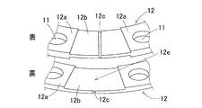
- the spacer-like member 12 may further have a thinnest portion 12c serving as a strain concentration portion as shown in FIGS. 5A to 5C, for example, in a part of the phase portion that is the thin portion 12b.
- the thin wall portion 12b has both main surfaces of the spacer member 12 recessed with respect to the thick wall portion 12a, and the phase portion between the bolt holes 11 on the front surface of the spacer member 12
- An intermediate protrusion 12d which is in the same plane as the thick portion 12a, is provided in the center so as to extend in the radial direction, so that the thin portion 12b is divided into two portions arranged in the circumferential direction.
- a groove extending in the radial direction is formed at each of the divided portions, and the bottom portion of the groove is the thinnest portion 12c.
- These thinnest portions 12c are sensor mounting positions 12e.
- the intermediate protrusion 12d in FIG. 5A does not exist in any of the second and third examples, and the thin portion 12b continues to the entire phase portion between the bolt holes 11.
- a groove extending in the radial direction is formed in the center of the thin portion 12b in the circumferential direction, and the bottom portion of the groove is the thinnest portion 12c.
- the thinnest part 12 c is formed by the groove as in the second example of FIG. 5B, but the thinnest part 12 c is biased in the circumferential direction from the center between the bolt holes 11. . 5B and 5C, the thinnest portion 12c is the sensor mounting position 12e.
- the strain sensor 13 (FIG. 4) is attached to the back surface of the thinnest portion 12c, that is, the main surface opposite to the groove constituting the thinnest portion 12c. May be. Instead, it may be attached to the bottom of the groove of the thinnest part 12c. In any case, the strain sensor 13 detects strain concentrated on the thinnest portion 12c.
- the illustrated phase portion is inverted between the front and the back, so that the position of the thinnest portion 12c is inverted between the front and back views. Appears.
- a diaphragm-type strain sensor 13 for detecting strain may be mounted on the spacer-like member 12 as shown in an example of the strain sensor in FIG.
- the diaphragm type strain sensor 13 includes a diaphragm 13a and a sensor element 13b that detects the distortion of the diaphragm 13a.
- the first and second examples of attachment are respectively provided with the thinnest portion 12c in the spacer-like member 12 itself, and the distortion formed by the diaphragm 13a and the sensor element 13a is provided here.
- a sensor 13 may be provided.
- the spacer member 12 is composed of one sheet. However, a plurality of spacer members (not shown) are combined to form one spacer member. You may comprise a member.
- FIG. 6 is a block diagram showing the system configuration of this wheel nut loosening detection device.
- arrows indicate the flow of detection data.
- the sensor unit 3 is provided for each wheel assembly 2A.
- Each sensor unit 3 includes a state detection sensor 21 including a strain sensor 13, a temperature sensor 14, and an acceleration sensor 15, and a communication device 16 that communicates detection data of these state detection sensors 21.
- a double wheel as shown in FIGS. 2 and 3A to 3C, one sensor unit 3 is provided for the two wheels 2 and 2 constituting the double wheel.
- reference numerals “A to Z” shown in the blocks of the wheel assembly 2A and the sensor unit 3 are codes for identifying individual pairs of the wheel assembly 2A and the sensor unit 3, and the wheel assembly 2A.
- the sensor unit 3 provided in the wheel assembly 2A are given the same reference numerals “AZ”.
- the information processing device 4 such as the vehicle-mounted device 4A or the portable or communication terminal 4B having the fastening state determination means 5 is provided for a plurality of sensor units 3, for example, for all the sensor units 3 provided in one vehicle. One is provided.
- the information processing apparatus 4 is mainly composed of a computer and a program.
- the information processing device 4 includes a communication device 22 that communicates with the communication device 16 of each sensor unit 3, an information processing unit 23, and a display unit 24.
- the information processing unit 23 is provided with the fastening state determination means 5. That is, the processor of the information processing device 4 is programmed to execute the fastening state determination means 5.
- the display unit 24 is a means for displaying an image on a screen composed of a liquid crystal display device or the like. The display unit 24 displays the result and the like determined by the fastening state determination unit 5 on the screen.
- the communication device 16 of the sensor unit 3 and the communication device 22 of the information processing device 4 perform wireless communication in accordance with standards for wireless communication and short-range wireless communication (for example, Bluetooth (registered trademark)).
- standards for wireless communication and short-range wireless communication for example, Bluetooth (registered trademark)
- the engagement state determination means 5 determines abnormality of the engagement state of the wheel nut 8 from the detection data of the strain sensor 13 according to a predetermined standard.
- the said fastening state determination means 5 determines the abnormality of the fastening state of the wheel nut 8 for every sensor unit 3.
- the fastening state determination means 5 includes a data storage unit 5a, a signal analysis unit 5b, and a state determination unit 5c.
- the data storage unit 5 a stores the detection signal of the state detection sensor 21 such as the strain sensor 13 and other determined information transmitted from the sensor unit 3.
- the signal analysis unit 5b analyzes a signal that is a preprocessing necessary for determining the abnormality in the fastening state.
- the state determination part 5c determines abnormality of the fastening state of the wheel nut 8 using the information analyzed by the signal analysis part 5b.
- the engagement state determination means 5 performs brake dragging based on the function of correcting the temperature drift of the distortion using the detected temperature of the temperature sensor 14 and the detected temperature of the temperature sensor 14 in addition to the determination of the abnormality of the engagement state of the wheel nut 8. It is possible to detect abnormal heat generation of the wheel 2 due to the above.
- the fastening state determination means 5 further has a function of detecting abnormality such as damage to a hub bearing (not shown) and puncture of the tire 10 from detection data of the acceleration sensor 15.
- the fastening state determination unit 5 has a function of displaying each detection result on the display unit 24.
- the frequency of each detection such as abnormality in the fastening state can be appropriately set by an input from an input means (not shown) provided in the information processing apparatus 4. Further, in the engagement state determination means 5, an abnormality in the engagement state can be detected even while the vehicle is traveling.
- the input means is, for example, a key switch or a touch panel provided on the screen of the display unit 24.
- the spacer type sensor unit 3 is installed at the wheel fastening portion (between the flange 6a of the hub 6 and the wheel 2 or between the wheel 2 and the wheel nut 8). Then, using the measurement data of the state detection sensor 21 such as the strain sensor 13 installed in the sensor unit 3, a fastening abnormality such as looseness of the wheel nut 8 or breakage of the hub bolt 7 is detected.
- the state detection sensor 21 mounted on the sensor unit 3 includes a strain sensor 13 and a temperature sensor 14 for detecting strain and temperature (for distortion temperature drift correction and detection of abnormal heating of wheels), and an acceleration 15 sensor, respectively.
- the wheel nut loosening detection device according to the present embodiment can also monitor the state during traveling.
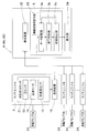
- FIG. 7 is a block diagram showing a method for using the wheel nut loosening detection device according to the present embodiment and a flow of operation. The supplementary explanation of the operation and configuration of the wheel nut loosening detection device will be given with reference to FIG.
- the sensor unit 3 is assembled between the hub 6 and the wheel nut 8, and the wheel nut 8 is assembled with a regular tightening torque.
- the state of components such as the wheel 2 is measured by the built-in state detection sensors 21, and the measurement data is transmitted to the communication terminal 4B or the vehicle-mounted device 4A.
- the measurement data is received from the sensor unit 3. Further, the measurement data is stored in the data storage unit 5a as input of vehicle type and part information and as reference data for abnormality determination.
- the vehicle type and part information may be input from the input device unit of the communication terminal 4B or the vehicle-mounted device 4A, or stored in the sensor unit 3 as initial setting data, and the stored data is communicated.
- the terminal 4B or the vehicle-mounted device 4A may be transmitted and the received data may be input.
- the sensor unit 3 measures the state of the component by each built-in state detection sensor 21.
- the measurement object is the distortion, temperature, acceleration, etc. of the spacer-like member 12.
- the communication terminal 4B or the vehicle-mounted device 4A performs the following processing.
- the data storage unit 5a, the signal analysis unit 5b, or the state determination unit 5c, the data storage unit, the signal analysis unit, or the state determination unit will be described below. Specify what will be done.
- the communication terminal 4B or the vehicle-mounted device 4A receives the measurement data from each sensor unit 3, corrects the temperature of the distortion data (data storage unit 5a) with the temperature data (signal analysis unit 5b), and uses the corrected distortion data. Then, a determination process of a fastening abnormality is performed (state determination unit 5c). Also, abnormal heat generation determination processing is performed based on the temperature data (data storage unit 5a) (state determination unit 5c). From the input specific information (data storage unit 5a) of the measurement part described above, past measurement data for the part is extracted (data storage part 5a), the fastening abnormality determination process (state determination part 5c), and Used in the abnormal heat generation determination process (state determination unit 5c).
- the sensor unit 3 includes the acceleration sensor 15
- frequency analysis is performed from the received acceleration data (data storage unit 5 a) (signal analysis unit 5 b), and abnormality determination processing for peripheral components of the wheel 2 is performed (state determination unit) 5c).
- the extracted past measurement data is also used for this process.
- each determination process it is determined whether there is an abnormality in the data (state determination unit 5c). For example, it is determined whether or not the data exceeds a threshold value, and whether or not there is a tendency to be different from detection data of other strain sensors 13 provided at a plurality of other locations of the sensor unit 3 (state determination unit 5c). . When there is no abnormality, “no abnormality” is displayed on the display unit 24, and when there is an abnormality, “abnormal” is displayed. Each measurement data and determination result are stored (data storage unit 5a).
- abnormalities such as looseness of the wheel nut 8 can be monitored and detected during operation such as running, the detection accuracy is excellent, the structure is simple, and the wheel is supported.
- the effect on rigidity is small.
- maintainability is improved, determination accuracy is improved, and determination criteria are quantified (abnormal portions can be determined).
- the sensor unit 3 can be easily attached to and detached from the vehicle, and has little influence on the vehicle weight, axle width, and support rigidity.
Landscapes
- Physics & Mathematics (AREA)
- General Physics & Mathematics (AREA)
- Force Measurement Appropriate To Specific Purposes (AREA)
Abstract
ホイールナット(8)の緩み等の異常を走行中等の稼働中に検出でき、検出の精度にも優れ、かつ構造が簡単でホイール(2)の支持剛性への影響が小さいセンサユニット(3)を提供する。スペーサ型のセンサユニット(3)と、締結状態判定手段(5)とを備える。センサユニット(3)は、ホイール(2)をハブ(6)に取付ける各ハブボルト(7)の頭部(7a)とホイールナット(8)との間にハブ(6)の全周に渡って介在し各ハブボルト(7)とホイールナット(8)とによる締め付け力を受ける変形発生用のリング状のスペーサ状部材(12)、および歪センサ(13)を備える。締結状態判定手段(5)は、車載器(4A)または携帯端末(4B)等の情報処理装置(4)に設けられる。
Description
本出願は、2015年3月30日出願の特願2015-067948の優先権を主張するものであり、その全体を参照により本願の一部をなすものとして引用する。
この発明は、自動車および各種産業機械の動力伝達系に使用されるハブとホイールとの間の締結部におけるホイールナットの緩みを検出するホイールナット緩み検出装置およびその緩み検出用のセンサユニットに関する。
自動車、特に大型商用車等においては、車輪脱落等の不具合防止として各車輪の締結状態を確認することが重要であると認識されている。そのため、ホイールナット締結時の締結トルク管理が法令化されている。このような締結状態の確認としては、外観、打音チェックによる点検が一般的である。しかし、稼働中の締結状態を高精度に判定出来る量産技術は無い為、定期メンテナンスの他に、運行前点検、運行途中点検等の日常点検を実施し、ナット緩み等の締結異常発生を防いでいる。
外観チェックについては、ナット締付後、ペイントマーカーでナットとホイール間の周方向位相を示したり、周方向位相が分かるキャップをナットに組み付けたりして、緩みによる周方向位相ズレを検出し易くする等の方法がある。また、打音チェックについては、一般的に点検者の経験則に基づく判定が主であるが、ハンマリング器具に加速度計を組み込み、ナット緩みやボルト損傷による共振周波数の変化を検出する診断ツールも存在する。
稼働中の車輪アセンブリの状態を監視する量産技術としては、TPMS(タイヤ空気圧監視装置)等があり、車両制御の為にタイヤ作用力を検出する方式も提案されている(例えば、特許文献1~3)。前記タイヤの作用力を検出する装置は、ホイール支持部(ハブ)とホイール間に、柱状部と板状部を有する弾性体を配置し、各部位に生じる応力、歪等の情報から、タイヤ接地面にかかる作用力を演算し検出する。この装置は、板状部に歪を増大させる応力集中部を設けるが、前記特許文献にその具体案は記載されていない。
上述した締結状態の確認のための方法および装置には、以下の問題がある。
(i)外観、打音による従来の確認手法では、ナット緩み、ボルト破損等の異常を走行中に検出できない。
(ii)点検者の経験則に基づく判定の場合、検出精度にばらつきがある。
(iii)前述の前記特許文献に記載の装置の様に、ハブとホイール間に連結固定される弾性部材を設けることで、構造が複雑になり、コストが高く、車両重量、車軸幅の増加、および車両の支持剛性にも影響する。
(i)外観、打音による従来の確認手法では、ナット緩み、ボルト破損等の異常を走行中に検出できない。
(ii)点検者の経験則に基づく判定の場合、検出精度にばらつきがある。
(iii)前述の前記特許文献に記載の装置の様に、ハブとホイール間に連結固定される弾性部材を設けることで、構造が複雑になり、コストが高く、車両重量、車軸幅の増加、および車両の支持剛性にも影響する。
この発明の目的は、ホイールナットの緩み等の異常を走行中等の稼働中に検出でき、検出の精度にも優れ、かつ構造が簡単でホイールの支持剛性への影響が小さいホイールナット緩み検出装置およびその緩み検出用のセンサユニットを提供することである。
この発明の一構成に係るホイールナット緩み検出用のセンサユニットは、ハブの全周に渡り設けられ、ホイールを前記ハブに取付ける複数のハブボルトの各頭部とそれぞれ対応する複数のホイールナットとの間に介在し前記複数のハブボルトとそれぞれ対応する前記複数のホイールナットとによる締め付け力を受ける変形発生用のリング状のスペーサ状部材であって、複数の周方向位相部位にそれぞれ形成され、前記複数のハブボルトがそれぞれ挿通される複数のボルト孔を有するスペーサ状部材と、前記複数のボルト孔のうちの少なくとも2つのボルト孔の間に設けられて前記スペーサ状部材の歪みを検出する少なくとも1つの歪センサとを備える。
この構成によると、前記リング状のスペーサ状部材は、円周方向に並ぶ複数のハブボルトの各頭部とそれぞれ対応するホイールナットとの間に介在しているため、いずれか一部のホイールナットに緩みが生じると、他のホイールナットとの締め付け力の差により前記スペーサ状部材に2つのボルト孔の間の周方向位相部位で歪みが生じる。この歪みが歪センサで検出され、その検出データから、異常の判定が可能になる。
このようにハブボルトとホイールナットとの間に介在するリング状のスペーサ状部材を用い、このスペーサ状部材の歪みを検出してホイールナットの締結状態の異常を検出するため、車両の走行中等の、ホイールが回転する稼働中にも締結状態の異常を検出できる。また、歪みを生じさせるための前記スペーサ状部材は、ハブボルトの頭部とホイールナットとの間に介在させるリング状の部材であり、このスペーサ状部材に歪センサを取付けた構成であるため、構造が簡単で、ホイールの支持剛性への影響も小さい。
なお、前記センサユニットは、ハブボルトの頭部とホイールナットとの間に介在していれば良く、例えば、ハブとホイール間、ダブルホイール間、ホイールとナット間等のいずれに配置されていても良い。
前記スペーサ状部材の周方向において、前記複数のホイールナットの最外径内の領域以外に凹みおよび/または欠如部分が形成されても良い。
この形状とすることで、ホイールナットの締付によってホイールの締結に関係する部材にかかる軸力を損なわず、強固に連結が可能になる。
なお、前記ホイールナットがワッシャ部を一体に有する場合は、前記最外径は、前記ワッシャ部を含む最外径である。
この形状とすることで、ホイールナットの締付によってホイールの締結に関係する部材にかかる軸力を損なわず、強固に連結が可能になる。
なお、前記ホイールナットがワッシャ部を一体に有する場合は、前記最外径は、前記ワッシャ部を含む最外径である。
前記スペーサ状部材は、前記少なくとも2つのボルト孔の間の周方向位相部位に、前記歪センサ、この歪センサの検出信号を通信する通信装置、並びに前記歪センサおよび前記通信装置に通電する電源が設けられていても良い。
前記歪センサの検出やその検出信号の通信のためには通信装置や電源が必要であるが、スペーサ状部材のボルト孔の間の周方向位相部位に前記通信装置および電源を配置することで、センサユニットをコンパクトに構成することができる。前記スペーサ状部材は、ボルト孔の存在する周方向位相部位では締め付けのためにある程度の肉厚が必要であるが、2つのボルト孔の間の周方向位相部位は薄くても良い。そのため、例えば、この薄くすることで生じる空間内に前記通信装置や電源を配置することで、センサユニットの全体としての肉厚を厚くすることなく、通信装置および電源を配置することができる。
前記スペーサ状部材の前記少なくとも2つのボルト孔の間の前記周方向位相部位が薄肉部であっても良い。
このように薄肉部を設けることで、センサや、通信装置、電源等の実装部位として利用し、その実装したセンサ等をスペーサ状部材の全体の肉厚から突出しないようにできる。そのため、前記スペーサ状部材を支障なく部材間に挟み込むことができる。また、前記薄肉部を設けることで歪を集中させることができ、歪みの検出の感度を向上させ、締結状態の異常判定の精度を向上させることができる。
このように薄肉部を設けることで、センサや、通信装置、電源等の実装部位として利用し、その実装したセンサ等をスペーサ状部材の全体の肉厚から突出しないようにできる。そのため、前記スペーサ状部材を支障なく部材間に挟み込むことができる。また、前記薄肉部を設けることで歪を集中させることができ、歪みの検出の感度を向上させ、締結状態の異常判定の精度を向上させることができる。
好ましい実施形態において、前記スペーサ状部材は、前記少なくとも2つのボルト孔の間の前記薄肉部である前記周方向位相部位の一部に、歪集中部となる最薄部を有しても良い。
このように最薄部を設けることで、スペーサ状部材の歪みがより一層集中し、歪みの検出の感度の向上、締結状態の異常判定の精度をより一層向上させることができる。
このように最薄部を設けることで、スペーサ状部材の歪みがより一層集中し、歪みの検出の感度の向上、締結状態の異常判定の精度をより一層向上させることができる。
前記少なくとも1つの歪センサは、前記スペーサ状部材に取付けられてこのスペーサ状部材の変形により歪むダイヤフラムと、このダイヤフラムに取付けられてこのダイヤフラムの歪みを検出するセンサ素子とで構成されていても良い。
スペーサ状部材自体に薄肉部を設けるのではなく、上記のようにダイヤフラムを設けてもスペーサ状部材の歪みを感度良く検出することができる。
スペーサ状部材自体に薄肉部を設けるのではなく、上記のようにダイヤフラムを設けてもスペーサ状部材の歪みを感度良く検出することができる。
前記センサユニットは、さらに、温度を検出する温度センサと、加速度を検出する加速度センサとを備えても良い。
歪センサの歪みの検出値は温度によって変わるため、温度センサで温度を検出し、温度補正を行うことが、締結状態の異常判定の精度向上の上で好ましい。また、温度センサにより、ブレーキ引きずり等による異常発熱の検知も可能になる。前記加速度センサによって、ハブベアリングの損傷や、タイヤパンク等の異常の検出も可能となる。
歪センサの歪みの検出値は温度によって変わるため、温度センサで温度を検出し、温度補正を行うことが、締結状態の異常判定の精度向上の上で好ましい。また、温度センサにより、ブレーキ引きずり等による異常発熱の検知も可能になる。前記加速度センサによって、ハブベアリングの損傷や、タイヤパンク等の異常の検出も可能となる。
前記センサユニットは、さらに、前記歪センサの検出データを送信する無線通信を行う無線通信手段を有しても良い。
前記センサユニットはホイールと共に回転するため、有線の配線ではスリップリング等の摺動する部品が必要となる。そのため、無線通信とすることが好ましい。前記無線通信手段には、種々の規格の近距離無線通信手段が採用され得る。
前記センサユニットはホイールと共に回転するため、有線の配線ではスリップリング等の摺動する部品が必要となる。そのため、無線通信とすることが好ましい。前記無線通信手段には、種々の規格の近距離無線通信手段が採用され得る。
この発明の一構成に係るホイールナット緩み検出装置は、前記センサユニットと、前記少なくとも1つの歪センサの検出データから所定の基準に従い前記ホイールナットの締結状態の異常を判定する締結状態判定手段とを備える。前記「所定の基準」は、任意に定めた基準で良い。
このように歪みの検出データから締結状態判定手段が所定の基準に従って締結状態の異常を判定するので、検出の精度に優れる。
前記締結状態判定手段は、前記異常の判定を行う頻度が任意に設定可能であり、かつ前記ホイールを備える車両の走行中に判定可能であることが好ましい。
前記ホイールが用いられる車両等の使用の形態がユーザ等によって大きく変わるため、使用の形態に応じた頻度で異常の判定が行われるようにすることが、使用に便利である。また、走行中に判定可能であると、走行中に生じたナットの緩みを検出可能になる。
前記ホイールが用いられる車両等の使用の形態がユーザ等によって大きく変わるため、使用の形態に応じた頻度で異常の判定が行われるようにすることが、使用に便利である。また、走行中に判定可能であると、走行中に生じたナットの緩みを検出可能になる。
請求の範囲および/または明細書および/または図面に開示された少なくとも2つの構成のどのような組合せも、本発明に含まれる。特に、請求の範囲の各請求項の2つ以上のどのような組合せも、本発明に含まれる。
この発明は、添付の図面を参考にした以下の好適な実施形態の説明から、より明瞭に理解されるであろう。しかしながら、実施形態および図面は単なる図示および説明のためのものであり、この発明の範囲を定めるために利用されるべきものではない。この発明の範囲は添付の請求の範囲によって定まる。添付図面において、複数の図面における同一の符号は、同一または相当する部分を示す。
この発明の第1の実施形態に係るホイールナット緩み検出装置の概要を示す説明図である。
図1のホイールナット緩み検出装置における車輪アセンブリのセンサユニットの取付部を示す破断斜視図である。
図2のセンサユニットのホイールへの取付形態の第1の例を示す部分斜視図である。
図2のセンサユニットのホイールへの取付形態の第2の例を示す部分斜視図である。
図2のセンサユニットのホイールへの取付形態の第3の例を示す部分斜視図である。
図2のセンサユニットの正面図である。
図2のセンサユニットにおける薄肉部の形態の第1の例を表側および裏側から示す部分斜視図である。
図2のセンサユニットにおける薄肉部の形態の第2の例を表側および裏側から示す部分斜視図である。
図2のセンサユニットにおける薄肉部の形態の第3の例を表側および裏側から示す部分斜視図である。
図1のホイールナット緩み検出装置の概念構成のブロック図である。
図1のホイールナット緩み検出装置の動作のフローをブロック構成で示す図である。
図2のセンサユニットにおける歪センサの一例を示す断面図である。
図8の歪センサのセンサユニットへの取付の第1の例を示す断面図である。
図8の歪センサのセンサユニットへの取付の第2の例を示す断面図である。
この発明の第1の実施形態を図面と共に説明する。図1に、第1の実施形態に係るホイールナット緩み検出装置Sを大型商用車に採用したシステムの全体を示す。このホイールナット緩み検出装置Sは、車両1の車輪アセンブリ2Aのホイール部に搭載されるスペーサ型のセンサユニット3と、車載器4Aまたは携帯端末4B等の情報処理装置4に設けられた締結状態判定手段5とで構成される。図1において、車両1は、大型商用車であるトラックである。車載器4Aは、車両1に搭載されたECU(電気制御ユニット)の情報を読み込むことができても良い。携帯端末4Bは、情報処理機能を備えた所謂スマートフォン等の携帯電話器、または携帯性を持つ緩み止め検出専用、または他のメンテナンス用途を含むメンテナンス専用の端末機である。締結状態判定手段5は、いずれか一つの情報処理装置4に設けられれば良いが、締結状態判定手段5を持つ車載器4Aや携帯端末4B等の複数の情報処理装置4を設けても良い。なお、前記締結状態判定手段5は、前記車載器4Aや携帯端末4Bに広域ネットワークを介して接続されるサーバ(図示せず)などの情報処理装置に設けられても良い。
図2は、前記車両1が大型商用車である場合に、後軸ダブルホイール部に前記センサユニット3を実装した図であって、その回転軸線を通る面にて切断して示す断面図である。車輪アセンブリ2Aでは、ハブ6のフランジ6aの片面に2つのホイール2,2を互いに反対に向けて重ね、フランジ6aの他の片面にブレーキドラム9を重ねている。これらホイール2,2とブレーキドラム9とを、ハブボルト7の頭部7aとホイールナット8との間に挟み込んで締め付け固定している。ハブボルト7は、ハブ6の円周方向の複数箇所に設けられ、前記フランジ6a、ホイール2,2、およびブレーキドラム9に設けられたボルト孔に挿通されている。なお、前記ハブ6は、車軸(図示せず)の外周に設置されるが、ハブベアリング(すなわち車輪用軸受)の一部を構成する部品であっても、ハブベアリングとは別に設けられた部品であっても良い。各ホイール2,2の外周にはタイヤ10が設けられ、ホイール2とタイヤ10とで車輪アセンブリ2Aが構成される。
センサユニット3は、ホイール2と同心の円形のリング状で板状の部品であり、この例では2つのホイール2,2間に位置して、前記各ハブボルト7の頭部7aとホイールナット8の間に介在し、これらハブボルト7とホイールナット8とで締め付けられている。センサユニット3は、円周方向の複数箇所にボルト孔11(図1)を有し、これらボルト孔11にハブボルト7が挿通されている。
図3A~3Cは、図2におけるセンサユニット3のホイールナット8による締め付け部を拡大して示す。
センサユニット3は、図3Aの第1の取付例のように、2つのホイール2,2の間に配置されても良い。代わりに、図3Bの第2の取付例のように、ホイール2とホイールナット8との間に配置されても良い。さらに代わりに、図3Cの第2の取付例のようにハブ6のフランジ6aとホイール2との間に配置されても良い。
センサユニット3は、図3Aの第1の取付例のように、2つのホイール2,2の間に配置されても良い。代わりに、図3Bの第2の取付例のように、ホイール2とホイールナット8との間に配置されても良い。さらに代わりに、図3Cの第2の取付例のようにハブ6のフランジ6aとホイール2との間に配置されても良い。
なお、センサユニット3は、ハブボルト7の頭部7aとホイールナット8との間であれば、ハブ6のフランジ6aとブレーキドラム9との間や、ブレーキドラム9とハブボルト7の頭部7aとの間など、ハブボルト7の頭部7aとハブ6のフランジ6aとの間に配置されても良いが、一般的にハブボルト7はハブ6のフランジ6aのボルト孔に圧入して固定されるため、ハブ6のフランジ6aよりもホイールナット8側に配置されるのが好ましい。
また、図3A~3Cの各例ではスペーサ型のセンサユニット3は後輪ダブルホイール部に配置されているが、このホイールナット緩み検出装置が適用される車輪アセンブリは、前輪のシングルタイヤ仕様であっても良い。
図4に本実施形態に係るセンサユニット3を示す。このセンサユニット3は、リング状で板状のスペーサ状部材12と、このスペーサ状部材12に取付けられた1つまたは複数の歪センサ13とを有する。歪センサ13は、例えば箔ひずみゲージ、線ひずみゲージ、半導体ひずみゲージである。スペーサ状部材12には、ホイール2の状態を検知する状態検知センサ21として、歪センサ13の他に、温度センサ14および加速度センサ15が取付けられる。この他に、ジャイロや回転センサ(いずれも図示せず)が設けられても良い。なお、前記状態検知センサ21は、前記各センサの総称である。また、スペーサ状部材12には、通信装置16および電源17が設けられる。この例では、通信装置16と電源17とを纏めて一つの部品とした電源・通信ユニット18が用いられている。
スペーサ状部材12は、ハブの各部位のハブボルト7とホイールナット8とによる締め付け力の差によって変形を生じさせるための部材であり、前述のように、各ハブボルト7を挿通させるボルト孔11が設けられている。スペーサ状部材12の材質については、鉄合金の様に高強度、かつ高剛性の金属材料で形成されていても、またアルミニウム合金の様に弾性が比較的高い金属材料にて形成されても良い。
スペーサ状部材12は後述する厚肉部12aを有する。スペーサ状部材12は、前記ホイールナット8の最外径内の領域では凹みおよび欠如部分のいずれもが存在しない形状であり、この領域は厚肉部12aに構成される。この形状とすることで、ホイールナット8の締付によってホイール2の締結に関係する部材にかかる軸力を損なわず、強固に連結が可能になる。なお、ホイールナット8がワッシャ部(図示せず)を一体に有する場合は、前記最外径は、前記ワッシャ部を含む最外径である。
スペーサ状部材12はさらに、薄肉部12bを有する。ボルト孔11の存在する位相部位、つまりボルト孔11の周囲の部分は厚肉部12aであるのに対して、ボルト孔11間の位相部位は薄肉部12bである。
薄肉部12bは、スペーサ状部材12の両主面が前記厚肉部12aよりも凹む形状であっても、スペーサ状部材12の一方の主面のみが厚肉部12aよりも凹む形状であっても良い。この薄肉部12bであるボルト孔11間の位相部位に、前記歪センサ13、温度センサ14、加速度センサ15等のセンサや、前記通信装置16、電源17、ならびに電源・通信ユニット18が実装される。なお、図4に示すように、スペーサ状部材12の一方の主面の内周部は、全周にわたる薄肉部であり、配線に利用されている。
スペーサ状部材12は、さらに、薄肉部12bである位相部位の一部に、例えば図5A~5Cに示すように、歪集中部となる最薄部12cを有しても良い。
図5Aの第1の例では、薄肉部12bはスペーサ状部材12の両主面が厚肉部12aに対して凹んでおり、かつスペーサ状部材12の表側の面ではボルト孔11間の位相部位の中央に厚肉部12aと同一平面となる中間突条部12dが半径方向に延びて設けられることで、薄肉部12bが円周方向に並ぶ2か所に分割されている。その各分割箇所に半径方向に延びる溝が形成されて、その溝の底部分が前記最薄部12cである。そして、これら最薄部12cが、センサ実装位置12eである。
図5Bおよび5Cの第2および第3の例では、いずれも図5Aの中間突条部12dが存在せず、薄肉部12bはボルト孔11間の位相部位の全体に続く。図5Bの第2の例では、薄肉部12bにおける円周方向の中央に、半径方向に延びる溝が形成されて、その溝の底部分が前記最薄部12cである。図5Cの第3の例では図5Bの第2の例と同じく溝によって最薄部12cが形成されているが、最薄部12cはボルト孔11間の中央よりも円周方向に偏っている。図5Bおよび5Cにおいて、最薄部12cが、センサ実装位置12eである。
薄肉部の形態の第1~第3の例において、前記歪センサ13(図4)は、最薄部12cの裏側、すなわち最薄部12cを構成する溝とは反対側の主面に取付けられても良い。代わりに、最薄部12cの溝の底部に取付けられても良い。いずれにしても、前記歪センサ13は、この最薄部12cに集中した歪みを検出する。
なお、図5A~5Cの各図は、図示した位相部分を表と裏で反転させて示しており、そのため表を示す図と裏を示す図とで、最薄部12cの位置が反転されて表れている。
なお、図5A~5Cの各図は、図示した位相部分を表と裏で反転させて示しており、そのため表を示す図と裏を示す図とで、最薄部12cの位置が反転されて表れている。
スペーサ状部材12自体に最薄部12cを設けるのではなく、図8の歪みセンサの一例に示すように、歪みを検出するダイヤフラム型の歪センサ13をスペーサ状部材12に実装しても良い。このダイヤフラム型の歪センサ13は、ダイヤフラム13aと、このダイヤフラム13aの歪みを検出するセンサ素子13bとで構成される。また、図9Aおよび9Bに取付の第1および第2の例をそれぞれに示すように、スペーサ状部材12自体に最薄部12cを設け、ここに前記のダイヤフラム13aとセンサ素子13aとでなる歪センサ13を設けてもよい。
また、スペーサ状部材12は、図5A~5C,図8ならびに図9Aおよび9Bでは1枚で構成するものとしたが、スペーサ状部材構成材(図示せず)を複数枚組み合わせて一つのスペーサ状部材を構成しても良い。
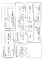
図6は、このホイールナット緩み検出装置のシステム構成を示すブロック図である。なお、図6において矢印は検出データの流れを示す。センサユニット3は、各車輪アセンブリ2A毎に設けられている。各センサユニット3は、歪センサ13、温度センサ14、加速度センサ15を含む状態検知センサ21と、これらの状態検知センサ21の検出データの通信を行う通信装置16とを備えている。なお、ダブルホイールの場合は、図2および図3A~3Cに示したように、そのダブルホイールを構成する2つのホイール2,2に対して一つのセンサユニット3が設けられる。なお、図6において、車輪アセンブリ2Aおよびセンサユニット3のブロック内に示した「A~Z」の符号は、車輪アセンブリ2Aおよびセンサユニット3からなる個々のペアを識別する符号であり、車輪アセンブリ2Aとその車輪アセンブリ2Aに設けられたセンサユニット3には、同一の符号「A~Z」を付してある。
前記締結状態判定手段5を持つ車載器4Aまたは携帯または通信端末4B等の情報処理装置4は、複数のセンサユニット3に対して、例えば1台の車両に設けられた全てのセンサユニット3に対して、1台設けられる。
情報処理装置4は、コンピュータとプログラムとで主に構成される。情報処理装置4は、前記各センサユニット3の通信装置16と通信を行う通信装置22と、情報処理部23と、表示部24とを有する。前記情報処理部23には、前記締結状態判定手段5が設けられている。すなわち、情報処理装置4のプロセッサは、締結状態判定手段5を実行するようにプログラムされている。表示部24は、液晶表示装置等からなる画面に画像を表示する手段である。表示部24は、前記締結状態判定手段5で判定された結果等を画面に表示する。
前記センサユニット3の通信装置16と、情報処理装置4の通信装置22とは、無線通信、近距離無線通信の規格(例えばブルートゥ-ス(登録商標))に応じて無線通信を行う。
前記締結状態判定手段5は、歪センサ13の検出データから所定の基準に従い前記ホイールナット8の締結状態の異常を判定する。前記締結状態判定手段5は、個々のセンサユニット3毎に、ホイールナット8の締結状態の異常を判定する。
締結状態判定手段5は、データ記憶部5a、信号解析部5b、および状態判定部5cを有する。データ記憶部5aが、センサユニット3から送信された、歪みセンサ13等の状態検知センサ21の検出信号、およびその他の定められた情報を記憶する。信号解析部5bは、締結状態の異常の判定のために必要な前処理となる信号の解析を行う。状態判定部5cは、信号解析部5bで解析された情報を用い、ホイールナット8の締結状態の異常を判定する。
締結状態判定手段5は、ホイールナット8の締結状態の異常の判定に加えて、温度センサ14の検出温度を用いて歪みの温度ドリフト補正を行う機能、および温度センサ14の検出温度から、ブレーキ引きずり等によるホイール2の異常発熱の検出が可能である。締結状態判定手段5はさらに、加速度センサ15の検出データからハブベアリング(図示せず)の損傷やタイヤ10のパンク等の異常を検出する機能を備える。締結状態判定手段5は、各検出結果を表示部24に表示させる機能を備える。
締結状態判定手段5において、締結状態の異常等の各検出の頻度が、情報処理装置4に設けられた入力手段(図示せず)からの入力によって適宜設定可能である。また、締結状態判定手段5において、締結状態の異常等が、車両の走行中も検出可能である。前記入力手段は、例えばキースイッチや、前記表示部24の画面上に設けられるタッチパネル等である。
本実施形態に係るホイールナット緩み検出装置によると、スペーサ型のセンサユニット3を車輪締結部(ハブ6のフランジ6aとホイール2の間、もしくはホイール2とホイールナット8との間等)に設置しており、センサユニット3に設置した歪みセンサ13等の状態検知センサ21の測定データを用いて、ホイールナット8の緩みやハブボルト7の破損等の締結異常を検出する。
センサユニット3に搭載する状態検知センサ21は、歪、温度(歪の温度ドリフト補正、および車輪の異常発熱検知用)をそれぞれ検出する歪みセンサ13および温度センサ14、ならびに加速度15センサを含む。
また、本実施形態に係るホイールナット緩み検出装置は、走行中の状態監視も可能である。
また、本実施形態に係るホイールナット緩み検出装置は、走行中の状態監視も可能である。
図7は、本実施形態に係るホイールナット緩み検出装置の使用方法および動作のフローをブロック構成で示す図である。図7を用いて、ホイールナット緩み検出装置の動作および構成の補足説明を行う。
まず、図7の上段に示すように、事前準備(セットアップ)として、センサユニット3をハブ6とホイールナット8の間に組付け、正規締付トルクでホイールナット8を組付ける。センサユニット3では、内蔵の各状態検知センサ21でホイール2等の部品の状態を測定し、その測定データを通信端末4Bまたは車載器4A等に送信する。通信端末4Bまたは車載器4Aでは、測定データをセンサユニット3から受信する。また、車種、部位の情報のインプット、および異常判定の基準データとして、前記測定データをデータ記憶部5aに記憶する。車種、部位の情報のインプットは、通信端末4Bまたは車載器4A等が持つ入力機器部から行っても良く、またセンサユニット3に初期設定用のデータとして記憶させておいて、その記憶データを通信端末4Bまたは車載器4Aに送信させ、その受信データがインプットされても良い。
運転中(緩み状態の検知)では、センサユニット3において、内蔵の各状態検知センサ21により、部品の状態を測定する。測定対象は、スペーサ状部材12の歪み、温度、加速度等である。これらの測定データは、通信端末4Bまたは車載器4A等に送信する。
通信端末4Bまたは車載器4Aでは、次の処理を行う。なお、データ記憶部5a、信号解析部5b、および状態判別部5cのいずれで行う処理であるかが明確となるように、以下に、データ記憶部、信号解析部、状態判別部のいずれによって処理されるかを明記する。
通信端末4Bまたは車載器4Aは、各センサユニット3から測定データを受信し、歪データ(データ記憶部5a)を温度データによって温度補正し(信号解析部5b)、その補正後の歪データを用いて締結異常の判定処理を行う(状態判定部5c)。また、温度データ(データ記憶部5a)によって異常発熱の判定処理を行う(状態判定部5c)。前述の測定部位のインプットされた固有情報(データ記憶部5a)から、その部位についての過去の測定データを抽出し(データ記憶部5a)、前記締結異常の判定処理(状態判定部5c)、および異常発熱の判定処理(状態判定部5c)に用いる。
センサユニット3が加速度センサ15を有する場合は、受信した加速度データ(データ記憶部5a)から周波数解析を行い(信号解析部5b)、ホイール2の周辺部品の異常判定の処理を行う(状態判定部5c)。この処理にも前述の抽出された過去測定データ(データ記憶部5a)が用いられる。
前記各判定の処理では、データに異常があるか否かを判定する(状態判定部5c)。例えば、データが閾値を超えているか、またセンサユニット3の複数の他の箇所に設けられた他の歪みセンサ13等の検出データと異なる傾向があるか否かを判定する(状態判定部5c)。
異常なしの場合は表示部24に「異常なし」と表示し、異常有りの場合は「異常」と表示する。また、各測定データおよび判定結果を保存する(データ記憶部5a)。
異常なしの場合は表示部24に「異常なし」と表示し、異常有りの場合は「異常」と表示する。また、各測定データおよび判定結果を保存する(データ記憶部5a)。
このように、このホイールナット緩み検出装置によると、ホイールナット8の緩み等の異常を走行中等の稼働中に状態監視して検出でき、検出の精度にも優れ、かつ構造が簡単でホイールの支持剛性への影響が小さい。また、メンテナンス性が向上し、判定精度が向上し、判定基準が定量化(異常部位の判別が可能)される。センサユニット3は、車両への着脱も容易で、車両重量、車軸幅、支持剛性への影響が小さい。
なお、上記実施形態は、自動車などの車両に適用した場合につき説明したが、この発明は、車両以外の産業機械における各種のホイールの締結部に適用することができる。
以上、実施形態に基づいてこの発明を実施するための形態を説明したが、今回開示された実施の形態はすべての点で例示であって制限的なものではない。この発明の範囲は上記した説明ではなくて特許請求の範囲によって示され、特許請求の範囲と均等の意味および範囲内でのすべての変更が含まれることが意図される。
2:ホイール
2A:車輪アセンブリ
3:センサユニット
5:締結状態判定手段
6:ハブ
7:ハブボルト
7a:ハブボルトの頭部
8:ホイールナット
11:ボルト孔
12:スペーサ状部材
13:歪センサ
2A:車輪アセンブリ
3:センサユニット
5:締結状態判定手段
6:ハブ
7:ハブボルト
7a:ハブボルトの頭部
8:ホイールナット
11:ボルト孔
12:スペーサ状部材
13:歪センサ
Claims (10)
- ハブの全周に渡り設けられ、ホイールを前記ハブに取付ける複数のハブボルトの各頭部とそれぞれ対応する複数のホイールナットとの間に介在し前記複数のハブボルトとそれぞれ対応する前記複数のホイールナットとによる締め付け力を受ける変形発生用のリング状のスペーサ状部材であって、複数の周方向位相部位にそれぞれ形成され、前記複数のハブボルトがそれぞれ挿通される複数のボルト孔を有するスペーサ状部材と、
前記複数のボルト孔のうちの少なくとも2つのボルト孔の間に設けられて前記スペーサ状部材の歪みを検出する少なくとも1つの歪センサとを備えた、ホイールナット緩み検出用のセンサユニット。 - 請求項1に記載のセンサユニットにおいて、前記スペーサ状部材の周方向において、前記複数のホイールナットの最外径内の領域以外に凹みおよび/または欠如部分が形成されたセンサユニット。
- 請求項1または請求項2に記載のセンサユニットにおいて、前記スペーサ状部材は、前記少なくとも2つのボルト孔の間の周方向位相部位に、前記歪センサ、この歪センサの検出信号を通信する通信装置、並びに前記歪センサおよび前記通信装置に通電する電源が設けられたセンサユニット。
- 請求項1ないし請求項3のいずれか1項に記載のセンサユニットにおいて、前記スペーサ状部材の前記少なくとも2つのボルト孔の間の前記周方向位相部位が薄肉部であるセンサユニット。
- 請求項4に記載のセンサユニットにおいて、前記スペーサ状部材は、前記少なくとも2つのボルト孔の間の前記薄肉部である前記周方向位相部位の一部に、歪集中部となる最薄部を有するセンサユニット。
- 請求項1ないし請求項4のいずれか1項に記載のセンサユニットにおいて、前記少なくとも1つの歪センサは、前記スペーサ状部材に取付けられてこのスペーサ状部材の変形により歪むダイヤフラムと、このダイヤフラムに取付けられてこのダイヤフラムの歪みを検出するセンサ素子とで構成されるセンサユニット。
- 請求項1ないし請求項6のいずれか1項に記載のセンサユニットにおいて、さらに、
温度を検出する温度センサと、
加速度を検出する加速度センサとを備えたセンサユニット。 - 請求項1ないし請求項7のいずれか1項に記載のセンサユニットにおいて、さらに、
前記歪センサの検出データを送信する無線通信手段を有するセンサユニット。 - 請求項1ないし請求項8のいずれか1項に記載のセンサユニットと、
前記少なくとも1つの歪センサの検出データから所定の基準に従い前記ホイールナットの締結状態の異常を判定する締結状態判定手段とを備えたホイールナット緩み検出装置。 - 請求項9に記載のホイールナット緩み検出装置において、前記締結状態判定手段は、前記ホイールを備える車両の走行中に前記ホイールナットの締結状態の異常を判定するように構成されるホイールナット緩み検出装置。
Applications Claiming Priority (2)
| Application Number | Priority Date | Filing Date | Title |
|---|---|---|---|
| JP2015067948A JP6466223B2 (ja) | 2015-03-30 | 2015-03-30 | ホイールナット緩み検出装置およびその緩み検出用のセンサユニット |
| JP2015-067948 | 2015-03-30 |
Publications (1)
| Publication Number | Publication Date |
|---|---|
| WO2016158586A1 true WO2016158586A1 (ja) | 2016-10-06 |
Family
ID=57005065
Family Applications (1)
| Application Number | Title | Priority Date | Filing Date |
|---|---|---|---|
| PCT/JP2016/059059 Ceased WO2016158586A1 (ja) | 2015-03-30 | 2016-03-22 | ホイールナット緩み検出用のセンサユニット、およびこれを備えた装置 |
Country Status (2)
| Country | Link |
|---|---|
| JP (1) | JP6466223B2 (ja) |
| WO (1) | WO2016158586A1 (ja) |
Cited By (2)
| Publication number | Priority date | Publication date | Assignee | Title |
|---|---|---|---|---|
| WO2018104511A3 (de) * | 2016-12-09 | 2018-08-16 | iq contec GmbH | Verbindungsvorrichtung, überwachungsverfahren und montagewerkzeug für eine verbindungsvorrichtung |
| WO2023026454A1 (ja) * | 2021-08-27 | 2023-03-02 | 太平洋工業株式会社 | ブラケット、及び緩み判定装置 |
Families Citing this family (10)
| Publication number | Priority date | Publication date | Assignee | Title |
|---|---|---|---|---|
| JP6677693B2 (ja) | 2017-10-20 | 2020-04-08 | ファナック株式会社 | 電動機装置 |
| SA118390641B1 (ar) * | 2018-05-27 | 2020-06-22 | سعيد جمعان الغامدي خالد | صامولة لربط عجلة الإطار مزودة بدائرة تنبيه إلكترونية |
| CN111551105B (zh) * | 2020-06-16 | 2022-02-11 | 襄阳吉盛邦机械有限公司 | 一种后轮毂加工用变形检测方法 |
| CN111976737B (zh) * | 2020-09-03 | 2024-03-19 | 摩登汽车有限公司 | 汽车的车轮松动监测系统及汽车 |
| JP7770184B2 (ja) * | 2021-12-27 | 2025-11-14 | Toyo Tire株式会社 | ホイールナット緩み予測装置、ホイールナット緩み予測方法、演算モデル生成システムおよび車両運用システム |
| WO2023144942A1 (ja) * | 2022-01-26 | 2023-08-03 | 太平洋工業株式会社 | 固定部材緩み検知装置、及び固定部材緩み警報装置 |
| CN119546936A (zh) * | 2022-07-27 | 2025-02-28 | 株式会社东海理化电机制作所 | 检测装置、状态检测装置和检测方法 |
| JP2024078910A (ja) * | 2022-11-30 | 2024-06-11 | 株式会社東海理化電機製作所 | 判定装置 |
| JP7533661B1 (ja) | 2023-03-20 | 2024-08-14 | いすゞ自動車株式会社 | 測定制御装置及び測定制御方法 |
| TWI909426B (zh) * | 2023-06-21 | 2025-12-21 | 為升電裝工業股份有限公司 | 車輪鬆脫偵測裝置 |
Citations (5)
| Publication number | Priority date | Publication date | Assignee | Title |
|---|---|---|---|---|
| JP2004198185A (ja) * | 2002-12-17 | 2004-07-15 | Honda Motor Co Ltd | 車両運動情報検出装置 |
| JP2007127586A (ja) * | 2005-11-07 | 2007-05-24 | Toyota Motor Corp | 圧力検出装置 |
| WO2008142841A1 (ja) * | 2007-05-14 | 2008-11-27 | Ntn Corporation | 軸受装置および軸受予圧検出装置 |
| JP2009128265A (ja) * | 2007-11-27 | 2009-06-11 | Ntn Corp | センサ付車輪用軸受 |
| JP2012088091A (ja) * | 2010-10-15 | 2012-05-10 | Nitto Seiko Co Ltd | ワッシャ型ロードセルおよびスラスト荷重検出機構 |
Family Cites Families (3)
| Publication number | Priority date | Publication date | Assignee | Title |
|---|---|---|---|---|
| US3033031A (en) * | 1959-07-27 | 1962-05-08 | Waukesha Bearings Corp | Tilting pad type thrust bearings having integral means for measuring thrust loads |
| JPS6161440U (ja) * | 1984-09-28 | 1986-04-25 | ||
| JPH0645106B2 (ja) * | 1989-02-08 | 1994-06-15 | 株式会社日立製作所 | ボルト締結方法 |
-
2015
- 2015-03-30 JP JP2015067948A patent/JP6466223B2/ja active Active
-
2016
- 2016-03-22 WO PCT/JP2016/059059 patent/WO2016158586A1/ja not_active Ceased
Patent Citations (5)
| Publication number | Priority date | Publication date | Assignee | Title |
|---|---|---|---|---|
| JP2004198185A (ja) * | 2002-12-17 | 2004-07-15 | Honda Motor Co Ltd | 車両運動情報検出装置 |
| JP2007127586A (ja) * | 2005-11-07 | 2007-05-24 | Toyota Motor Corp | 圧力検出装置 |
| WO2008142841A1 (ja) * | 2007-05-14 | 2008-11-27 | Ntn Corporation | 軸受装置および軸受予圧検出装置 |
| JP2009128265A (ja) * | 2007-11-27 | 2009-06-11 | Ntn Corp | センサ付車輪用軸受 |
| JP2012088091A (ja) * | 2010-10-15 | 2012-05-10 | Nitto Seiko Co Ltd | ワッシャ型ロードセルおよびスラスト荷重検出機構 |
Cited By (2)
| Publication number | Priority date | Publication date | Assignee | Title |
|---|---|---|---|---|
| WO2018104511A3 (de) * | 2016-12-09 | 2018-08-16 | iq contec GmbH | Verbindungsvorrichtung, überwachungsverfahren und montagewerkzeug für eine verbindungsvorrichtung |
| WO2023026454A1 (ja) * | 2021-08-27 | 2023-03-02 | 太平洋工業株式会社 | ブラケット、及び緩み判定装置 |
Also Published As
| Publication number | Publication date |
|---|---|
| JP6466223B2 (ja) | 2019-02-06 |
| JP2016188769A (ja) | 2016-11-04 |
Similar Documents
| Publication | Publication Date | Title |
|---|---|---|
| JP6466223B2 (ja) | ホイールナット緩み検出装置およびその緩み検出用のセンサユニット | |
| US10408709B2 (en) | Device for determining wheel fastening state using server | |
| JP6639838B2 (ja) | ホイール締結状態判定装置 | |
| US8434947B2 (en) | Sensor-equipped bearing for wheel | |
| US8523446B2 (en) | Sensor equipped wheel support bearing assembly | |
| JP2004177411A (ja) | 変形状態における力を測定するために装着されたサスペンション制御装置 | |
| JP6545501B2 (ja) | 車輪締結状態の判定装置 | |
| JP2007155079A (ja) | センサ付車輪用軸受 | |
| US9014992B2 (en) | Sensor equipped wheel support bearing assembly | |
| JP5063270B2 (ja) | センサ付車輪用軸受 | |
| JP4925625B2 (ja) | センサ付車輪用軸受 | |
| JP5455357B2 (ja) | タイヤ作用力検出装置 | |
| JP2010230406A (ja) | センサ付車輪用軸受 | |
| JP2006145436A (ja) | センサ付き転がり軸受装置 | |
| JP5072551B2 (ja) | センサ付車輪用軸受 | |
| JP5219423B2 (ja) | センサ付車輪用軸受 | |
| JP2011230544A (ja) | タイヤ空気圧低下検出装置、方法およびプログラム | |
| JP2007198814A (ja) | 車輪用転がり軸受装置 | |
| JP5219424B2 (ja) | センサ付車輪用軸受 | |
| JP2007057301A (ja) | センサ付車輪用軸受 | |
| JP6385215B2 (ja) | 車輪作用力検出装置 | |
| JP2008249566A (ja) | センサ付車輪用軸受 | |
| JP2007163246A (ja) | センサ付車輪用軸受 | |
| JP2007078597A (ja) | センサ付車輪用軸受 | |
| JP2008051199A (ja) | センサ付車輪用軸受 |
Legal Events
| Date | Code | Title | Description |
|---|---|---|---|
| 121 | Ep: the epo has been informed by wipo that ep was designated in this application |
Ref document number: 16772467 Country of ref document: EP Kind code of ref document: A1 |
|
| NENP | Non-entry into the national phase |
Ref country code: DE |
|
| 122 | Ep: pct application non-entry in european phase |
Ref document number: 16772467 Country of ref document: EP Kind code of ref document: A1 |