WO2016158512A1 - 水処理管理装置及び方法 - Google Patents
水処理管理装置及び方法 Download PDFInfo
- Publication number
- WO2016158512A1 WO2016158512A1 PCT/JP2016/058772 JP2016058772W WO2016158512A1 WO 2016158512 A1 WO2016158512 A1 WO 2016158512A1 JP 2016058772 W JP2016058772 W JP 2016058772W WO 2016158512 A1 WO2016158512 A1 WO 2016158512A1
- Authority
- WO
- WIPO (PCT)
- Prior art keywords
- chemical
- water
- boiler
- amount
- tank
- Prior art date
- Legal status (The legal status is an assumption and is not a legal conclusion. Google has not performed a legal analysis and makes no representation as to the accuracy of the status listed.)
- Ceased
Links
Images


Classifications
-
- F—MECHANICAL ENGINEERING; LIGHTING; HEATING; WEAPONS; BLASTING
- F22—STEAM GENERATION
- F22B—METHODS OF STEAM GENERATION; STEAM BOILERS
- F22B37/00—Component parts or details of steam boilers
- F22B37/02—Component parts or details of steam boilers applicable to more than one kind or type of steam boiler
- F22B37/48—Devices or arrangements for removing water, minerals or sludge from boilers ; Arrangement of cleaning apparatus in boilers; Combinations thereof with boilers
- F22B37/52—Washing-out devices
-
- F—MECHANICAL ENGINEERING; LIGHTING; HEATING; WEAPONS; BLASTING
- F22—STEAM GENERATION
- F22B—METHODS OF STEAM GENERATION; STEAM BOILERS
- F22B37/00—Component parts or details of steam boilers
- F22B37/02—Component parts or details of steam boilers applicable to more than one kind or type of steam boiler
- F22B37/56—Boiler cleaning control devices, e.g. for ascertaining proper duration of boiler blow-down
Definitions
- the present invention relates to a water treatment management device and a water treatment management method in a boiler facility.
- the low-pressure boiler feed pump starts to operate when the boiler water level falls below the set lower limit value, and is controlled to stop or adjust the flow rate according to the water level when the boiler water level reaches the set upper limit value. Therefore, the feed water pump operates irregularly or the flow rate fluctuates according to the combustion state of the boiler.
- the feed water flow rate of the feed water mother pipe greatly fluctuates because the feed water pumps of each boiler operate irregularly or the flow rate fluctuates.
- microcomputer control control based on an on / off signal of a water supply pump, control based on a pulse signal or an analog signal of a flow meter, etc. are common.
- the microcomputer control it is determined that an amount of water supply corresponding to the combustion state and combustion time of the boiler is supplied to the boiler, and the operation time of the chemical injection pump is determined accordingly.
- the chemical injection pump is not necessarily linked with the operation of the water supply pump, and the chemical injection pump operates when the water supply pump is not moving, or vice versa. There are times when it does not. Therefore, in the microcomputer control, the chemical concentration in the water supply is likely to fluctuate significantly.
- the chemical injection pump In the method of controlling the chemical injection pump by the on / off signal of the water supply pump, the chemical injection pump is operated when the water supply pump is in operation, so the fluctuation of the chemical concentration in the water supply becomes smaller than the microcomputer control. However, immediately after the feed water pump is started and immediately before it is stopped, the flow rate of the feed water is slightly reduced, so that the chemical concentration becomes high.
- the number of strokes of the chemical injection pump is determined in proportion to the feed water flow rate, so the chemical concentration in the feed water is close to the target concentration. be able to.
- this control when the capacity of the water supply pump or the chemical injection pump is reduced, an error between the actual chemical injection amount and the target chemical injection amount increases.
- Low pressure boilers often inject one or two multifunctional cleaning agents that combine multiple types of compounds with water treatment effects, but the quality of the feed water or feed water fluctuates due to drain recovery or fluctuations in raw water quality.
- the balance of required amounts such as the amount of alkali adjuvant, amount of oxygen scavenger, amount of anticorrosive, and amount of dispersant may fluctuate, causing specific components to be insufficient or excessive.
- the pH adjusting agent can be adjusted according to the carbonic acid concentration in the feed water as described in JP2010-159965A.
- the chemical injection concentration is constant, it is possible to check the average chemical injection concentration over a period of time by recording the amount of chemical decrease and the integrated value of the feed water flow rate.
- the chemical reduction amount and the integrated value of the feed water flow rate must be confirmed. It is not realistic to constantly monitor drain recovery and raw water quality fluctuations that are affected by the steam usage, weather, temperature, etc. in the process, and change the discharge conditions of the chemical injection pump. It was not possible to confirm whether or not it was managed. Therefore, it was not possible to comprehensively judge the water treatment status in the boiler equipment.
- the present invention has been made in view of the above circumstances, and it is an object of the present invention to provide a water treatment management apparatus and method capable of comprehensively judging the water treatment status in boiler facilities.
- a water supply line for supplying water from a water supply tank to a boiler, a water supply flow rate measuring means for measuring a water supply flow rate flowing through the water supply line, and a chemical solution containing a boiler water treatment chemical stored in a chemical tank
- a chemical injection pump for injecting into a water supply line or a water supply tank, a chemical amount measuring means for measuring the amount of chemical stored in the chemical tank, and a blow determining means for determining whether or not the continuous blow operation of the boiler is appropriate
- a control means for controlling the discharge rate of the chemical injection pump in proportion to the feed water flow rate measured by the feed water flow rate measuring means, the determination result of the blow determination means, and the chemical injection control result by the control means And determining means for determining the water treatment status of the boiler equipment, wherein the control means changes the target chemical injection amount every first predetermined period, and the water supply flow rate measuring means Accordingly, the amount of chemical used for each first predetermined period is determined from the feed water flow rate per first predetermined period measured and the target chemical injection amount for the first
- the apparatus further includes a calculation unit that calculates a boiler operation rate, and the determination unit is based on a determination result of the blow determination unit, a chemical injection control result by the control unit, and the boiler operation rate.
- the water treatment management device characterized by judging the water treatment status of the boiler equipment.
- the blow determining means is configured to open and close an electromagnetic valve of a continuous blow line of the boiler and a detection value of a blow flow meter or a flow sensor provided in the continuous blow line.
- a water treatment management device characterized by determining whether or not the operation of continuous blow is appropriate.
- the blow determination means is continuously based on opening / closing of a solenoid valve of a continuous blow line of the boiler and a detection value of a temperature sensor provided in the continuous blow line.
- a water treatment management device for determining whether or not a blow operation is appropriate.
- a water supply line for supplying water to the boiler from the water supply tank, a water supply flow rate measuring means for measuring a water supply flow rate flowing through the water supply line, and a chemical solution containing the boiler water treatment chemical stored in the chemical tank Measured by a chemical injection pump for injecting into a water supply line or a water supply tank, a chemical liquid amount measuring means for measuring the amount of chemical liquid stored in the chemical tank, a calculating means for calculating a boiler operating rate, and the water supply flow rate measuring means
- the control means for controlling the discharge amount of the chemical injection pump in proportion to the flow rate of the supplied water, the determination of judging the water treatment status of the boiler equipment based on the boiler operation rate and the chemical injection control result by the control means And the control means changes the target chemical injection amount every first predetermined period, and the water supply per the first predetermined period measured by the water supply flow rate measuring means.
- the amount of medicinal solution used for each first predetermined period is obtained from the amount and the target drug injection amount for the first predetermined period, and from the measurement result of the medicinal solution amount measuring means, in the second predetermined period longer than the first predetermined period.
- a chemical liquid decrease amount in a chemical tank is obtained, the chemical liquid usage amounts corresponding to a plurality of first predetermined periods in the second predetermined period are integrated, a chemical liquid decrease estimated amount in the second predetermined period is obtained, and the chemical tank is obtained.
- a water treatment management device that compares an amount of decrease in internal chemical with the estimated amount of decrease in chemical and controls the chemical injection pump based on the comparison result.
- the chemical liquid amount measuring unit detects a pressure due to the chemical liquid in the chemical tank, and a water level detects the chemical water level height in the chemical tank.
- a water treatment management device characterized in that it is either a meter or a weight meter that detects the weight of the chemical in the chemical tank.
- control means sets the target discharge amount to be a target discharge amount obtained by multiplying a feed water flow rate measured by the feed water flow rate measurement means by a proportional coefficient.
- a water treatment management device that controls a pump and corrects the proportionality coefficient based on a difference between the chemical solution decrease amount in the chemical tank and the estimated chemical solution decrease amount.
- a plurality of the boilers are provided, and the water supply line includes a water supply mother pipe connected to the water supply tank and a plurality of water supplies branched from the water supply mother pipe.
- Each water supply branch pipe is connected to each boiler, and each water supply branch pipe is provided with a water supply pump, and the chemical injection pump is supplied with a chemical injection to the water supply mother pipe or the water supply tank.
- a water treatment management device characterized by:
- the water supply line is provided with a sensor for detecting a temperature or quality of the water supply, and the control means is configured to detect the target drug injection based on a detection result of the sensor.
- a water treatment management device characterized by changing the amount.
- a supply water line for supplying makeup water to the feed water tank and a sensor for detecting temperature or water quality are provided in each of the feed water lines, and the control means includes: A water treatment management device, wherein a drain recovery rate is calculated from detection results of each sensor, and the target chemical injection amount is changed based on the drain recovery rate.
- a flow meter is provided in a makeup water line that supplies makeup water to the feed water tank, and the control means includes an integrated value of a flow rate measurement value of the flow meter, A water treatment management device, wherein a drain recovery rate is calculated from an integrated value of flow rate measurement values of the feed water flow rate measuring means, and the target chemical injection amount is changed based on the drain recovery rate.
- the water supply line is provided with a first electric conductivity meter, and the boiler includes a second electric conductivity meter, and the second electric conductivity meter.
- the solenoid valve of the continuous blow line is closed, and when the measured value becomes a predetermined value or more, the solenoid valve is opened.
- a water treatment management apparatus wherein the boiler concentration is calculated from a measured value of a rate meter and a measured value of the second electrical conductivity meter, and the target chemical injection amount is changed based on the concentrated value.
- the boiler has a built-in electric conductivity meter, and the control means is configured such that the measured value of the electric conductivity meter becomes a predetermined value or more.
- the water treatment management device is characterized in that the target chemical injection amount is decreased until the measured value becomes less than the predetermined value.
- a chemical injection pump for injecting a chemical solution containing a boiler water treatment chemical stored in a chemical tank into a water supply line or a water supply tank for supplying water from the water supply tank to the boiler is controlled.
- a water treatment management method for determining a treatment status a step of measuring a feed water flow rate flowing through the feed water line, a step of controlling a discharge amount of the chemical injection pump in proportion to the measured feed water flow rate, and a first predetermined
- a step of changing a target chemical injection amount for each period a step of obtaining a chemical solution usage amount for each first predetermined period from the feed water flow rate per the first predetermined period and the target chemical injection amount for the first predetermined period;
- the method further includes a step of calculating a boiler operating rate, the result of determining whether the operation of continuous blowing of the boiler is appropriate, the result of the chemical injection control by the control of the chemical injection pump, A water treatment management method characterized by judging a water treatment status of boiler equipment based on a boiler operation rate.
- a water treatment management method for determining a treatment status a step of measuring a feed water flow rate flowing through the feed water line, a step of controlling a discharge amount of the chemical injection pump in proportion to the measured feed water flow rate, and a first predetermined
- a step of changing a target chemical injection amount for each period a step of obtaining a chemical solution usage amount for each first predetermined period from the feed water flow rate per the first predetermined period and the target chemical injection amount for the first predetermined period;
- the control that causes the chemical injection pump to be proportional to the feed water flow rate in real time, and the comparison between the chemical solution reduction target range obtained from the chemical injection target concentration and the integrated water supply amount and the chemical reduction amount in the chemical tank in a predetermined period Combined with feedback control that corrects the amount of drug delivered by the medication pump based on the results, the chemical concentration in the water supply can be stably maintained within the target range even in systems where the flow rate varies greatly in a short period of time. Can do.
- the boiler plant can be maintained by fully exhibiting the effects of the water treatment chemicals, scale prevention and proper blow management can be achieved, and energy saving operation can be performed. Further, it is possible to prevent an increase in the amount of blown water and an increase in chemical cost due to an excessive amount of chemical injection.
- the present invention it is possible to comprehensively determine the water treatment status of the boiler equipment based on the determination result of whether the continuous blow operation of the boiler is appropriate, the boiler operation rate, and the chemical injection control result. it can.
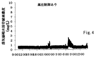
- FIG. 2 is a graph showing a dissolved oxygen concentration in steam condensed water in Example 1.
- 5 is a graph showing a dissolved oxygen concentration in steam condensed water in Comparative Example 1.
- 6 is a graph showing the pH of steam condensed water in Example 2.
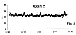
- 6 is a graph showing the pH of steam condensed water in Comparative Example 2.
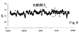
- 10 is a graph showing the pH of steam condensed water in Comparative Example 3.
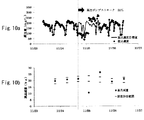
- FIG. 10a is a graph showing the amount of chemical injection in Example 3
- FIG. 10b is a graph showing the amount of medicine decrease.
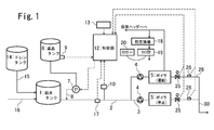
- FIG. 1 is a block diagram of a boiler water supply facility equipped with a water treatment management device according to an embodiment.
- Water supply in a water supply tank 1 is branched from a water supply mother pipe 2 and a water supply mother pipe 2.
- the water supply pump 4 provided in each water supply branch pipe 3 is supplied to each boiler 5.
- a chemical solution containing boiler water treatment chemical is stored in the chemical tank 6, and this chemical solution is injected into the feed water mother pipe 2 by a chemical injection pump 7 and a chemical injection nozzle 8.
- the chemical tank 6 is provided with a chemical amount sensor 9 for measuring the chemical amount.
- the water supply mother pipe 2 is provided with a flow meter 10 such as an ultrasonic flow meter and a temperature sensor 17, and these detection signals are input to the controller 12.
- the controller 12 is connected to an input means 13 such as a touch panel and a keyboard for inputting a target chemical concentration in the water supply.
- the water treatment management device is suitable as a water treatment management device for a water supply facility in which a large number of small once-through boilers are installed, but other than the water supply facility of a small once-through boiler, a boiler whose flow rate greatly varies in a short period of time. It is also suitable for water supply equipment.
- the water supply pump 4 may be operated by on / off control according to the water level of the boiler 5 or may be operated by inverter control, and the control method is not particularly limited.
- the chemical injection point by the chemical injection nozzle 8 is preferably the water supply tank 1 or the water supply mother pipe 2 when a large number of small once-through boilers are installed. This is because chemicals can be added more uniformly by taking a distance as much as possible until water is supplied to individual boilers.
- the chemical concentration in the water supply can be quickly controlled by pouring the water supply pipe 2 into the medicine.
- a check valve corresponding to the pressure of the water supply tank 1 or the water supply mother pipe 2 to be connected is preferably installed on the discharge side of the chemical injection pump 7.
- the chemicals used are liquid products or powders dissolved in liquid.
- Other conditions pH, specific gravity, etc. are not particularly limited.
- the chemical tank 6 has a cylindrical shape or a prismatic shape in which the horizontal cross-sectional area is uniform from the upper part to the lower part.
- the chemical amount sensor 9 it is preferable to use a chemical tank 6 having a capacity and a horizontal cross-sectional area as small as possible within a range where there is no problem in use.
- the chemical tank 6 preferably has an alarm function in preparation for an emergency.
- an emergency situation when the chemical injection amount does not enter the target range multiple times due to liquid leakage from the chemical tank 6 or the chemical injection pump 7, or when there is no chemical in the chemical tank 6, Wire breakage may be considered. Since the amount of decrease in the chemical solution in the chemical tank 6 is monitored by the chemical amount sensor 9, a function for notifying the operator via the controller 12 and a communication device (not shown) when the water level falls below a predetermined water level. Is preferably provided.
- a pressure sensor can be used as the chemical amount sensor 9 for measuring the chemical amount in the chemical tank 6, for example. Since the pressure sensor detects the head pressure of the chemical solution from the sensor position to the water surface, it is preferable that the pressure sensor is installed in the horizontal direction with a hole formed in the lowermost side surface of the chemical tank 6. By multiplying the water level detected by the pressure sensor and the horizontal sectional area of the chemical tank 6 determined in advance, the amount of chemical in the chemical tank 6 is obtained. Therefore, a pressure sensor having a pressure range that can be measured is larger than the water pressure at the highest water level of the chemical tank 6. A pressure sensor that is resistant to chemicals is used.
- the upper limit value of the pressure range is excessively larger than the water pressure at the highest water level of the chemical tank 6, the detection resolution of the chemical liquid amount increases and the detection accuracy of the chemical liquid amount change in the chemical tank 6 decreases. It is preferable that the upper limit value of the pressure range is slightly larger than the water pressure at the highest water level of the chemical tank 6 than the excessively large pressure range.
- a water level meter that detects the height of the chemical level in the chemical tank 6 and a weigh scale that detects the chemical weight in the chemical tank 6 can also be used.
- the flow meter 10 is preferably capable of outputting an instantaneous flow rate and an integrated flow rate, but may be capable of outputting only an instantaneous flow rate signal.
- the integrated flow rate is calculated by accumulating the instantaneous flow rate in the calculation unit of the controller 12.
- the flow meter 10 outputs only the integrated flow rate, it can be handled by converting the integrated value in a short interval to the average flow rate in the calculation unit, but there is a time lag between the start of water supply and the time when drug injection is performed.
- the flow meter 10 is desirably capable of outputting an instantaneous flow rate as a signal.
- the controller 12 controls the discharge flow rate of the chemical injection pump 7 in proportion to the flow rate signal from the flow meter 10.
- a PLC programmable logic controller
- the input unit and output unit of the controller 12 have a small resolution and a high calculation speed.
- the controller 12 basically controls the chemical injection pump 7 in proportion to the output signal of the flow meter 10. Specifically, the controller 12 multiplies the detected flow rate signal of the flow meter 10 by a proportional coefficient to generate a chemical injection signal, and gives the chemical injection signal to the drive circuit of the chemical injection pump 7 to perform the chemical injection. Let it be done.
- the target chemical injection amount (target chemical injection concentration) is determined every first predetermined period, and the pump capacity (%) is changed at the ratio of the nth target chemical injection amount / (n-1) target chemical injection amount.
- the target chemical injection amount is determined from the temperature and quality of the feed water, the drain recovery rate, the boiler 5 concentration, and the like. A method for determining the target drug injection amount will be described later.
- the first predetermined period for determining the target chemical injection amount is determined according to the drain recovery or the fluctuation of the raw water supply water quality.
- the target dose is preferably determined every 1 minute to 1 day, more preferably every 10 minutes to 60 minutes.
- the controller 12 calculates a chemical usage amount, in other words, a chemical decrease amount in the chemical tank 6 from the target chemical injection concentration and the feed water flow rate (integrated flow rate) during the first predetermined period.
- the controller 12 calculates the estimated amount of drug decrease at This estimated amount of medicine decrease is an integrated value of the amount of medicine used in a plurality of first predetermined periods included in the second predetermined period.
- the predetermined time corresponding to the second predetermined period or the predetermined integrated flow rate value is preferably determined under the condition that the water level difference corresponding to the amount of decrease in the chemical liquid in the chemical tank 6 is 50 mm or more. If it is 50 mm or less, the ratio of the chemical solution reduction amount per resolution of the chemical solution amount sensor 9 to the chemical reduction amount in the second predetermined period increases, and the error from the actual chemical injection amount increases.
- the periods T1, T2,..., Tn each correspond to a first predetermined period, and the total period from T1 to Tn corresponds to a second predetermined period.
- the controller 12 determines that the actual drug decrease amount in the chemical tank 6 in the second predetermined period obtained by using the chemical amount sensor 9 coincides with the estimated drug decrease amount obtained by integrating the chemical use amount in the second predetermined period. Whether or not, specifically, whether or not the target range including an allowable error is exceeded. If the target range is out of the range, the proportionality coefficient is corrected to match the target value. The controller 12 multiplies the feed water flow rate signal by the corrected proportionality coefficient to generate a chemical injection signal, and inputs it to the drive circuit of the chemical injection pump 7 to correct the chemical injection amount. For example, the controller 12 increases the proportionality coefficient when the chemical decrease amount obtained using the chemical amount sensor 9 is below the target range, and decreases the proportionality coefficient when the chemical decrease amount exceeds the target range.
- the change rate of the proportionality coefficient may be limited so that the corrected proportionality coefficient falls within ⁇ 50% of the proportionality coefficient before correction.
- the chemical injection signal after multiplying the proportionality coefficient may be corrected based on the difference between the expected chemical reduction amount and the actual chemical reduction amount.
- the control to make the discharge amount of the chemical injection pump 7 proportional to the detected feed water flow rate of the flow meter 10 in real time and the chemical decrease amount in the predetermined period (second predetermined period) are confirmed and the chemical injection amount signal is finely adjusted.
- the chemical concentration in the feed water is stably maintained within the target range even in systems where the flow rate fluctuates greatly in a short period of time, such as the water supply piping of small once-through boilers installed in multiple cans. be able to.
- the temperature of the feed water is measured using the temperature sensor 17, and the target chemical injection amount is changed at any time according to the saturated dissolved oxygen concentration at the measured temperature.
- the oxygen scavenger can be injected more efficiently and economically.
- the required amount of oxygen scavenger is obtained by the following formula 1, and the target amount of the chemical solution is determined according to the amount.
- the measurement principle of the temperature sensor 17 does not matter, but the measurement temperature range needs to sufficiently cover the fluctuation range of the feed water temperature.
- the temperature sensor 17 is installed in the feed water tank 1 or the feed water mother pipe 2 closer to the boiler 1 than the feed water tank 1. Although it is desirable to directly immerse the detection unit of the temperature sensor 17 in the water supply, the detection unit may be installed on the surface of the pipe so that the detection unit is covered with a heat insulating material so as not to release the temperature.
- the target drug injection amount may be determined using the drain recovery rate.
- the drain temperature, the makeup water temperature, and the feed water temperature are measured, and the electrical conductivity is determined for the makeup water and the feed water using the following formula 2 and the conductivity meter.
- Detecting and calculating using the following formula 3, and detecting the dissolved substance concentration (water quality) in the makeup water and feed water using the following formula 4 and a flow meter installed in the makeup water line 16 ( 6) and the integrated value of the flow meter 10 installed in the feed water main pipe 2 or the total integrated value of the flow meter installed in the feed water branch pipe connected to each boiler 5 (see FIG. 6)
- the dissolved substance concentration is detected using, for example, a chloride ion concentration detected using a chloride ion meter, a potassium concentration detected using a potassium meter, a sodium concentration detected using a sodium meter, and a calcium meter. Such as calcium concentration.
- the drain recovery rate may be obtained using other mathematical formulas and methods.
- the collected drain is stored in the drain tank 14 and supplied to the water supply tank 1 through the drain line 15.
- the quality of the feed water may vary greatly due to fluctuations in the raw water quality.
- the calculation unit converts the acid consumption (pH 4.8) into the amount, and calculates the target chemical injection amount based on the obtained acid consumption (pH 4.8), thereby determining the discharge amount of the chemical solution.
- the amount of alkali component added by the chemical can be obtained from the following equations 6 and 7.
- Target chemical injection amount necessary alkali component amount (acid consumption (pH 8.3)) / acid consumption (pH 8.3) generated from chemical solution 1 (mg / L)
- P1 Target boiler hydroxide consumption (pH 8.3) (mgCaCO 3 / L)
- the boiler 5 has a built-in electric conductivity meter, and when the measured value of the electric conductivity meter falls below a predetermined lower limit value, the solenoid valve of the continuous blow line is closed, and when the measured value exceeds the predetermined upper limit value, the continuous blower is continuously blown.
- the controller 12 uses the boiler water electrical conductivity measured by the electrical conductivity meter built in the boiler 5 and the water supply measured by the electrical conductivity meter provided in the feed water mother pipe 2 or the feed water branch pipe 3. Using the electrical conductivity, the concentration is calculated according to the following equation (8).
- the controller 12 can obtain the target chemical injection amount using the following formula 9 from the enrichment of the boiler 5 and the maintenance concentration in the boiler 5. If the boiler has information for calculating the degree of enrichment or the degree of enrichment, there is a method of inputting the information to the controller 12 as it is.
- Concentration Boiler water electrical conductivity / Feed water electrical conductivity (Equation 8)
- Target drug dosage (mg / L) maintenance concentration in can / concentration (Equation 9)
- the chemical concentration in the boiler water can be more reliably managed within the target range.
- the measured value of the electric conductivity meter is set to a predetermined upper limit value (if there is an upper limit value for blow control, it is set separately from the upper limit value). If the measured value exceeds the upper limit value, the target dose may be reduced for a certain period. This can prevent the occurrence of carry over.
- the water treatment status of the boiler water supply equipment can be determined mainly by three factors: “chemical injection status”, “boiler continuous blow operation status”, and “boiler operation status” when the quality of the makeup water does not change. Therefore, it is possible to comprehensively determine the water treatment status of the boiler water supply facility by giving the above-described chemical injection control device a signal that can determine the operation status of the continuous blow of the boiler and a signal that can determine the boiler operating rate. It becomes possible.
- the operation status of the continuous blow of the boiler 5 can be determined based on the presence / absence of voltage supply to the electromagnetic valve 25 provided in the continuous blow line 28 of each boiler and the detected value of the temperature sensor 26.
- the temperature sensor 26 may be inserted into the piping of the continuous blow line 28 to measure the temperature of the blow water, or may be installed on the surface of the piping to measure the piping temperature.
- the detected value of the temperature sensor 26 rises when there is no voltage supply to the solenoid valve 25 and the solenoid valve 25 is closed, it is determined that the boiler water is leaking from the solenoid valve 25 and blowing is not appropriate. .
- voltage is supplied to the solenoid valve 25 and the solenoid valve 25 is open if the detected value of the temperature sensor 26 does not rise above a certain level, the continuous blow line 28 or the solenoid valve 25 may be clogged or blocked. It is judged that the nature is high.
- a blow flow meter (not shown) may be installed in the blow line 28.
- the operation status of the continuous blow of the boiler can be determined based on the presence / absence of voltage supply to the solenoid valve 25 provided in the continuous blow line 28 of each boiler and the detected value of the blow flow meter. For example, when there is no voltage supply to the solenoid valve 25 and the solenoid valve 25 is closed, if the blow flow meter detects the flow rate, it is determined that the boiler water is leaking from the solenoid valve 25 and the blow is not appropriate.
- the presence or absence of voltage supply to the solenoid valve 25 may be confirmed directly by using the power supply itself as a signal.
- a clamp-type current sensor may be installed on the power cable, or a reed switch may be installed on the solenoid valve 25. It may be confirmed indirectly.
- the boiler operating status can be calculated by monitoring a combustion command signal that controls the combustion state of the boiler 5.
- the operation rate is obtained by calculating the ratio of the time during which the boiler 5 is in the combustion state during the monitoring target period.
- the boiler operation rate may be estimated from on / off of the feed water pump 4 and opening / closing of the solenoid valve 25. In this case, when the boiler 5 is burning continuously, the interval at which the feed water pump 4 and the electromagnetic valve 25 operate is confirmed in advance. When the period during which the operation of the feed water pump 4 and the electromagnetic valve 25 cannot be detected greatly exceeds the interval, it is determined that the combustion of the boiler 5 has stopped. Thus, the boiler operation rate can be estimated by determining the combustion state of the boiler 5.
- the controller 12 acquires the detection value of the temperature sensor 26 (or blow flow meter) and monitors the presence or absence of voltage supply to the solenoid valve 25, thereby continuously blowing each boiler 5. Determine whether the operation is appropriate. Furthermore, the controller 12 monitors the combustion command signal of the boiler 5, the on / off of the feed water pump 4, or the opening / closing of the electromagnetic valve 25 to calculate the boiler operating rate. As described above, the controller 12 detects whether or not the amount of chemicals injected into the water supply is within the target range.
- the controller 12 When the amount of chemical injection in the water supply is within the target range, the operation of continuous blowing of each boiler is appropriate, and the operation rate of each boiler in a certain period is equal to or higher than the set rate, The water treatment status of the boiler water supply equipment is judged to be good. If any one of these three conditions is not achieved, the water treatment status may be bad, so the controller 12 outputs an alarm that prompts the operator to confirm and respond.
- the above embodiment is an example of the present invention, and the present invention may have a configuration other than the above.
- the chemical injection control device is given a signal that can determine the operation status of the continuous blow of the boiler and a signal that can determine the boiler operating rate has been described.
- the controller 12 determines the water treatment status of the boiler water supply equipment based on whether the chemical injection amount in the water supply is within the target range and whether the continuous blow operation of each boiler 5 is appropriate. Alternatively, the controller 12 determines the water treatment status of the boiler water supply equipment based on whether the chemical injection amount in the water supply is within the target range and whether the operation rate of each boiler 5 in a certain period is equal to or higher than the set rate. To do. Compared to the case where both a signal for determining the operation status of the continuous blow of the boiler and a signal for determining the boiler operating rate are given, the water treatment status of the boiler water supply facility can be easily determined.
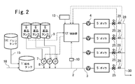
- FIG. 2 shows an embodiment configured in this way.
- the required amount of individual drug components increases for one component and decreases for other components, which greatly balances the required amount of the drug component.
- the water treatment can be economically performed by individually controlling the drug components.
- a chemical tank 6 and a chemical injection pump 7 are prepared for each chemical component, and chemical liquid amount information for each chemical tank 6 is input to the controller 12 to obtain individual chemical reduction amounts. The discharge amount of each chemical injection pump 7 is controlled.
- the controller 12 obtains at least one information of feed water temperature, feed water quality, drain recovery rate, and boiler concentration, and for each chemical tank 6 based on the obtained information, according to the feed water quality, or The target amount of chemical injection can be changed so that the chemical concentration in the feed water is constant or the chemical concentration in the boiler water is constant.
- the number and type of chemical tanks 6 are not limited.
- the other configuration of FIG. 2 and its control method are the same as those of FIG.
- the chemical solution includes potassium hydroxide (5% product) as a pH adjuster, hydrazine monohydrate (20% product) as an oxygen scavenger, and a polyacrylic having a molecular weight of 4000 as a scale inhibitor. What dissolved the acid was used.
- Example 1 As the boiler 5, two experimental boilers (maximum evaporation amount 500 kg / h) assuming a small once-through boiler are installed.
- the chemical injection control method of the present invention is applied to the feed water pipe 2 of the boiler feed water facility shown in FIG. Used to administer.
- the medicinal point was set at a point 500 mm from the outlet of the water supply tank.
- a SUS chemical injection nozzle 8 having an inner diameter of 6 mm and an outer diameter of 8 mm with respect to the pipe diameter of 40 A was inserted to the center of the water supply mother pipe 2 to perform chemical injection.
- a die light tank (N-type) 50L manufactured by Dailite Co., Ltd. was used as the chemical tank 6. Processing was performed so that a chemical amount sensor could be screwed into the bottom of the tank.
- KV-1000 manufactured by Keyence Corporation, KV-40DA as an input unit, and KV-40AD as an output unit were used.
- HT1-020KP- manufactured by Senses Co., Ltd. as the chemical volume sensor (pressure sensor) 9 02-V was used.
- the integrated flow rate of the flow meter 10 was obtained from a pulse signal of 1 pulse / 0.1 L, and the instantaneous flow rate was obtained from an analog signal in which 0-3500 L / h was 4-20 mA.
- the detected pressure 0-20 kPa of the pressure sensor 9 was input to the controller 12 as 4-20 mA.
- the dosing pump 7 adjusted the injection volume by controlling the number of strokes per minute by setting 0-38 mL / min to 4-20 mA.
- the boiler 5 was set to a high combustion fixed operation.
- the amount of water supply was 400 L / h per boiler, and the capacity of the water supply pump 4 was 1350 L / h.
- the temperature of the water supply tank 1 was changed to 20, 40, and 80 ° C. every few hours for operation.
- the feed water temperature was measured by attaching OMRON E52-CA10AE-N (K thermocouple) to the pipe surface of the feed water mother pipe 2 in the vicinity of the feed water tank outlet and covering with a heat insulating material from above.
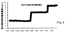
- Saturated dissolved oxygen concentration was calculated
- FIG. The transition of the saturated dissolved oxygen concentration in the feed water is shown in FIG.
- the chemical solution used contained 10% hydrazine monohydrate as a deoxygenating component, and the amount of oxygen removed by the chemical solution 1 mg / L was 0.065 mg / L.
- Target chemical injection amount (mg / L) saturated dissolved oxygen concentration at feed water temperature (mg / L) /0.065 (Equation 12)
- the water treatment status was judged based on the chemical injection amount, the blow operating status, and the boiler operating rate.
- Whether or not the chemical injection amount is within the target range was determined at minute intervals. “Good” if it is within the target range, “Cautions” if the judgment outside the target range is 2 times or less in succession, and “ ⁇ ” if the judgment outside the target range is 3 times or more in succession. “Warning” was evaluated in three stages.
- the operating condition of the blow is “good” when the piping temperature of the continuous blow line 28 rises by 5 ° C. or more when power is supplied to the solenoid valve 25 for each boiler 5, and the temperature rise is 5 ° C. or less.
- “ ⁇ CAUTION” In the case of 2 times or less in succession, “ ⁇ CAUTION”, and in the case where the temperature rise is 5 ° C. or less and 3 times or more in succession, “X warning” was judged in 3 stages.
- the power supply to the solenoid valve 25 is as follows. When the clamp sensor CTT-10-CLS-CV5 manufactured by U_RD Co., Ltd. is attached to the power cable and the voltage output value is 100 mV or more, the power supply to the solenoid valve 25 is It was judged.
- E52-CA10AE-N 1M of OMRON Corporation is pasted as a temperature sensor 26 on the piping surface of the continuous blow line 28 between the solenoid valve 25 and the blow collecting pipe 30 of each boiler 5, and the pipe of the continuous blow line 28 The temperature was measured.
- the piping temperature may not rise sufficiently even if the continuous blow is normal. If the time from when the solenoid valve 25 is closed until the next continuous blow solenoid valve 25 is opened is 20 minutes or less, and when the time from when the continuous blow is opened to close is 10 seconds or less, the continuous Judgment of proper blow operation was made.
- the boiler operation rate was calculated for each boiler 5. From the current output value of the clamp sensor described above, it is determined that the solenoid valve 25 has been opened and burned for 15 minutes. The boiler operation rate was calculated. If the boiler operation rate is 5% or less for less than 7 consecutive days, “Good”, and if the day of 5% or less continues for 7 or more consecutive days, the operation rate is too low. Judgment was made in two stages, “ ⁇ warning”.
- Example 1 The same procedure as in Example 1 was conducted except that a constant amount of chemical injection was injected into the water supply at 70 mg / L (assumed dissolved oxygen removal amount: 4.55 mg / L).
- FIG. 5 shows the result of logging the dissolved oxygen concentration in the steam condensed water obtained by cooling the boiler steam with the heat exchanger 18 every 20 seconds.
- Table 1 shows an example of the value of dissolved oxygen concentration in steam condensed water.
- Example 1 the dissolved oxygen concentration in the steam condensed water could be kept low by increasing the number of strokes of the chemical injection pump 7 according to the saturated dissolved oxygen concentration at the average feed water temperature every 10 minutes. Since the feedback control is performed, the dissolved oxygen concentration in the steam temporarily rises at the boundary where the feed water temperature changes, but the dissolved oxygen concentration converged to 1 mg / L or less.
- Comparative Example 1 when the chemical injection amount is constant and the feed water temperature is 20 ° C. or 40 ° C., the dissolved oxygen concentration in the feed water is larger than the deoxygenation ability by the chemical, and the dissolved oxygen concentration that shifts to steam is There were many.
- the water treatment effect could be effectively demonstrated without excessively injecting chemicals by changing the target chemical injection amount according to the feed water temperature.
- Example 2 As shown in FIG. 6, a blow flow meter 24 is installed in the blow line 28 instead of the temperature sensor 26. After the blow water was cooled by the heat exchanger 18, the pH was measured by the pH meter 21, and the measured value was input to the data logger 20. Moreover, the feed water flowmeter 23 was installed in each boiler 5 separately. In this boiler water supply facility, the acid consumption (pH 8.3) is set with the target value of the boiler water pH set to 11.5 in consideration of the concentration obtained from the values of the individual boiler feed flow meter 23 and blow flow meter 24. Was infused to a dose of 250 (mgCaCO 3 / L).
- the boiler water is continuously taken out from the boiler 5 through the blow line 28 at a rate of 200 ml / min, cooled by the heat exchanger 18, the pH of the steam condensed water is measured by the pH meter 21, and the measured value is the data logger 20.
- FIG. 7 shows the result of logging every minute.
- the drain recovery rate was obtained from the measurement results of the flow meter 22 (oval flow pet EG) installed in the makeup water line 16 and the flow meter 10.
- One experimental boiler maximum evaporation: 500 kg / h) assuming a small once-through boiler was operated at high combustion.
- the continuous blow setting of the boiler 5 was set to an upper limit of 300 mS / m and a lower limit of 250 mS / m in terms of the electric conductivity meter attached to the boiler.
- the vapor pressure was 0.7 MPa.
- the required chemical injection amount was determined using the following formula 13.
- the acid consumption (pH 8.3) generated by the chemicals used was 4.5 (mgCaCO 3 / L) per 100 mg / L.
- the water treatment status was determined based on the chemical injection amount, the blow operating status, and the boiler operating rate in the same manner as in Example 1.
- Example 2 was more stable in pH than Comparative Example 2 and Comparative Example 3. This is because the chemical injection control was performed so as to keep the acid consumption (pH 8.3) in the boiler water within a certain range in consideration of the effects of drain recovery and concentration.
- Comparative Example 2 drug injection was carried out so as to keep the concentration of feed water constant without considering drain recovery and concentration.
- Comparative Example 3 in consideration of the effect of drain recovery, chemical injection was performed so as to keep the acid consumption (pH 8.3) in the supplied water constant.
- Comparative Example 3 has a larger variation in pH value.
- the drain recovery rate decreases, and when the electrical conductivity of the makeup water increases, the concentration decreases.
- the drain recovery rate increases and the electrical conductivity of the makeup water decreases, the degree of concentration increases. Therefore, it can be said that there is a certain degree of buffering function regarding the acid consumption (pH 8.3).
- the fluctuation range of pH in boiler water is smaller in Comparative Example 2 than in Comparative Example 3.
- the change in pH was not absorbed by the function alone, and the effectiveness of Example 2 was confirmed.
- Example 3 Using the same boiler water supply equipment as in Example 1, the proportional coefficient between the target chemical injection amount, that is, the chemical injection pump discharge amount and the instantaneous water supply flow rate was changed according to the 20-minute average value of the saturated dissolved oxygen concentration based on the water supply temperature. Furthermore, feed water flow 100m every 3 and chemical reduction of the period of the cumulative drug decrease assumed value compared in the controller 12, if not within ⁇ 10% of the cumulative drug decrease assumed value, the cumulative drug decreases The proportionality coefficient was changed by the difference between the estimated amount and the (calculated actual) decrease amount of the chemical solution. However, after confirming the 3rd time of the chemical injection amount (chemical reduction amount), the stroke length of the chemical injection pump 7 was changed from 100% to 30% on the assumption that the capacity of the chemical injection pump 7 was reduced.
- the target chemical injection amount that is, the chemical injection pump discharge amount and the instantaneous water supply flow rate was changed according to the 20-minute average value of the saturated dissolved oxygen concentration based on the water supply temperature. Furthermore, feed water flow 100m every
- the feed water temperature fluctuates from 15 ° C. to 85 ° C. due to drain recovery, and the result of calculating the target chemical injection concentration from the following equation 15 using the saturated dissolved oxygen concentration at the feed water temperature is shown by the solid line in FIG. Show.
- the used chemical solution contained 10% hydrazine monohydrate as a deoxygenating component, and the amount of oxygen removed by 1 mg / L of the chemical solution was 0.065 mg / L. The safety factor was multiplied by 1.5.
- Required dosage (mg / L) Saturated dissolved oxygen concentration at feed water temperature (mg / L) /0.065 ⁇ 1.5 (Equation 15)
- the actual dosing concentration every 20 minutes is plotted in FIG. 10a.
- This chemical injection concentration was derived from the difference between the estimated amount of chemical decrease confirmed at every feed water flow rate of 100 m 3 and the measured chemical solution decrease amount, and the difference between the instantaneous water supply flow rate and the chemical injection pump discharge capacity.
- An error range of the chemical decrease amount in the chemical tank 6 and the estimated chemical decrease amount for each feed water flow rate of 100 m 3 is plotted in FIG.
- the dose length temporarily decreases as shown in FIG. 10b by changing the stroke length of the dose pump 7 from 100% to 30%.
- the predetermined injection concentration can be maintained again at the sixth injection amount confirmation.
- the target injection concentration is changed for each relatively short period of time, in order to automatically adjust the injection concentration, when the discharge amount of the injection pump is changed due to fluctuations in drain recovery or feed water quality, Even if the target chemical injection concentration range cannot be maintained due to a decrease in the capacity of the chemical injection pump 7 or the water supply pump 4, the water treatment effect can be exerted economically and maximally without disturbing human hands. Water treatment management can be performed.
- the water treatment status was determined based on the chemical injection amount, the blow operating status, and the boiler operating rate in the same manner as in Example 1.
Landscapes
- Engineering & Computer Science (AREA)
- Physics & Mathematics (AREA)
- Thermal Sciences (AREA)
- Mechanical Engineering (AREA)
- General Engineering & Computer Science (AREA)
- Feeding, Discharge, Calcimining, Fusing, And Gas-Generation Devices (AREA)
Abstract
ボイラ設備における水処理状況を総合的に判断することができる水処理管理装置及び方法を提供する。水処理管理装置は、給水流量を測定する流量計(10)と、薬液を給水ライン又は給水タンクに注入する薬注ポンプ(7)と、薬品タンク(6)内の薬液量を計測するセンサ(9)と、流量計(10)により測定結果に比例して薬注ポンプ(7)の吐出量を制御する制御器(12)と、ボイラ(5)の連続ブローの動作が適正か否か判定する手段と、この判定結果と制御器(12)による薬品注入制御結果とに基づいて、ボイラ設備の水処理状況を判断する判断手段とを備える。
Description
本発明は、ボイラ設備における水処理管理置及び水処理管理方法に関する。
通常、低圧ボイラの給水ポンプは、ボイラ水位が設定下限値以下になった場合に作動開始し、ボイラ水位が設定上限値に達すると停止又は水位に応じた流量調整を行うように制御される。そのため、給水ポンプは、ボイラの燃焼状態に応じて不定期に稼動したり、流量が変動したりする。小型貫流ボイラを複数設置して運転している場合、各ボイラの給水ポンプが不定期に稼動又は流量変動するため、給水母管の給水流量は大きく変動することになる。
小型貫流ボイラの薬液注入の制御としては、マイコン制御、給水ポンプのオン/オフ信号に基づく制御、流量計のパルス信号やアナログ信号による制御等が一般的である。
マイコン制御では、ボイラの燃焼状態及び燃焼時間に応じた量の給水がボイラに供給されたものと判断し、それに応じて薬注ポンプの稼動時間が決定される。このマイコン制御では、薬注ポンプは給水ポンプの稼動と必ずしも連動しておらず、給水ポンプが動いていないときに薬注ポンプが動いたり、反対に給水ポンプが動いていても薬注ポンプが稼動しなかったりする場合がある。そのため、マイコン制御では、給水中の薬品濃度が大幅に変動し易い。
給水ポンプのオン/オフ信号により薬注ポンプを制御する方法では、給水ポンプが稼動している時に薬注ポンプが稼動するため、マイコン制御より給水中での薬品濃度の変動は小さくなる。しかし、給水ポンプの起動直後や停止直前は給水流量がやや少なくなるため、薬品濃度が高くなる。
給水流量計のパルス信号又はアナログ信号により薬注ポンプを制御する方法では、給水流量に比例して薬注ポンプのストローク数が決定されるため、給水中の薬品濃度を目標濃度に近いものとすることができる。しかし、この制御では、給水ポンプ又は薬注ポンプの能力が低下した場合に、実際の薬注量と目標薬注量との誤差が大きくなる。
低圧ボイラは水処理効果を持つ化合物を複数種組合せた多機能清缶剤を一剤または二剤で注入することが多いが、ドレン回収または原水水質の変動により給水水質または給水温度が変動し、アルカリ補助剤量、脱酸素剤量、防食剤量、分散剤量等の必要量のバランスが変動して、特定の成分が不足または過剰となることがあった。
防食成分は、給水に対する添加濃度で管理する方法と、ボイラ水中濃度で管理する方法とがある。前者の方法は、ドレン回収の有無によらず給水中濃度を一定に保つように薬注する。後者の方法を、ボイラ水の電気伝導率が設定上限値に達するとブロー水を排出し、設定下限値になるとブロー水の排出を止めることで濃縮度を管理しているボイラに適用した場合、ドレン回収率や給水水質の変動により給水の電気伝導率が変動すると濃縮度が変動するため、給水流量に比例させて薬注を行っても、ボイラ水中の薬剤濃度を一定に管理できなかった。
前述したような給水に対する薬注濃度が維持できない課題と、ボイラの稼動条件により必要な薬注濃度が変動する課題とが複合的に作用することにより、ボイラ水処理を最適に保つことは困難であった。薬品濃度が目標値よりも低いと、防食剤の効果が不十分となって腐食が進行したり、脱酸素剤の脱酸素効果が小さくなり蒸気に多量の酸素が移行して復水配管での腐食を発生させたりする等、水処理効果が不十分となることがある。一方、薬品を過剰に添加した場合には、ボイラ水中の電気伝導率が過度に高くなり、キャリーオーバーが発生したり、薬品コストが増加したりする。
ドレン回収又は原水水質の変動により、薬注目標値、すなわち薬注ポンプ吐出量を変更する方法としては、特開2010-159965で挙げられたような給水中の炭酸濃度に応じてpH調整剤の薬注ポンプの稼働時間を決定する方法や、特開平10-82503のように給水温度に応じて薬注ポンプの稼働時間を決定する方法などがあるが、いずれも先に述べたような薬注ポンプまたは給水ポンプの性能低下などによる吐出量の変化には対応できていない。
薬注濃度が一定の場合には薬品減少量と給水流量積算値を記録することで、人の手で期間平均の薬注濃度を確認することも可能だが、ドレン回収または原水水質の変動に応じて薬注ポンプの吐出条件を切り替える場合には、その都度薬品減少量及び給水流量積算値を確認しなければならない。プロセスでの蒸気使用状況、天候、気温等に左右されるドレン回収や原水水質の変動を常に把握し、薬注ポンプの吐出条件を変更することは現実的でなく、薬注濃度を目標通りに管理できているか否か確認することはできなかった。そのため、ボイラ設備における水処理状況を総合的に判断することができなかった。
本発明は、以上の実情に鑑みてなされたものであり、ボイラ設備における水処理状況を総合的に判断することができる水処理管理装置及び方法を提供することを課題とする。
[1] 給水タンクからボイラに給水を供給するための給水ラインと、前記給水ラインを流れる給水流量を測定する給水流量測定手段と、薬品タンクに貯留されたボイラ水処理薬品を含有する薬液を前記給水ライン又は給水タンクに注入する薬注ポンプと、前記薬品タンク内に貯留された薬液の量を計測する薬液量計測手段と、前記ボイラの連続ブローの動作が適正か否か判定するブロー判定手段と、前記給水流量測定手段により測定された給水流量に比例して前記薬注ポンプの吐出量を制御する制御手段と、前記ブロー判定手段の判定結果、及び前記制御手段による薬品注入制御結果に基づいて、ボイラ設備の水処理状況を判断する判断手段と、を備え、前記制御手段は、第1所定期間ごとに目標薬注量を変更し、前記給水流量測定手段によって測定される該第1所定期間当たりの給水流量と、該第1所定期間の目標薬注量とから該第1所定期間ごとの薬液使用量を求め、前記薬液量計測手段の計測結果から、前記第1所定期間より長い第2所定期間における薬品タンク内薬液減少量を求め、前記第2所定期間内の複数の第1所定期間に対応する前記薬液使用量を積算して、該第2所定期間における薬液減少想定量を求め、前記薬品タンク内薬液減少量と前記薬液減少想定量とを比較し、比較結果に基づいて前記薬注ポンプを制御することを特徴とする水処理管理装置。
[2] [1]において、ボイラ稼働率を算出する算出手段をさらに備え、前記判断手段は、前記ブロー判定手段の判定結果、前記制御手段による薬品注入制御結果、及び前記ボイラ稼働率に基づいて、ボイラ設備の水処理状況を判断することを特徴とする水処理管理装置。
[3] [1]又は[2]において、前記ブロー判定手段は、前記ボイラの連続ブローラインの電磁弁の開閉と、該連続ブローラインに設けられたブロー流量計又はフローセンサの検出値とに基づいて、連続ブローの動作が適正か否か判定することを特徴とする水処理管理装置。
[4] [1]又は[2]において、前記ブロー判定手段は、前記ボイラの連続ブローラインの電磁弁の開閉と、該連続ブローラインに設けられた温度センサの検出値とに基づいて、連続ブローの動作が適正か否か判定することを特徴とする水処理管理装置。
[5] 給水タンクからボイラに給水を供給するための給水ラインと、前記給水ラインを流れる給水流量を測定する給水流量測定手段と、薬品タンクに貯留されたボイラ水処理薬品を含有する薬液を前記給水ライン又は給水タンクに注入する薬注ポンプと、前記薬品タンク内に貯留された薬液の量を計測する薬液量計測手段と、ボイラ稼働率を算出する算出手段と、前記給水流量測定手段により測定された給水流量に比例して前記薬注ポンプの吐出量を制御する制御手段と、前記ボイラ稼働率、及び前記制御手段による薬品注入制御結果に基づいて、ボイラ設備の水処理状況を判断する判断手段と、を備え、前記制御手段は、第1所定期間ごとに目標薬注量を変更し、前記給水流量測定手段によって測定される該第1所定期間当たりの給水流量と、該第1所定期間の目標薬注量とから該第1所定期間ごとの薬液使用量を求め、前記薬液量計測手段の計測結果から、前記第1所定期間より長い第2所定期間における薬品タンク内薬液減少量を求め、前記第2所定期間内の複数の第1所定期間に対応する前記薬液使用量を積算して、該第2所定期間における薬液減少想定量を求め、前記薬品タンク内薬液減少量と前記薬液減少想定量とを比較し、比較結果に基づいて前記薬注ポンプを制御することを特徴とする水処理管理装置。
[6] [1]乃至[5]のいずれかにおいて、前記薬液量計測手段が、前記薬品タンク中の薬液による圧力を検出する圧力センサ、前記薬品タンク中の薬品の水位高さを検出する水位計、又は前記薬品タンク中の薬品重量を検出する重量計のいずれかであることを特徴とする水処理管理装置。
[7] [1]乃至[6]のいずれかにおいて、前記制御手段は、前記給水流量測定手段により測定された給水流量に対して比例係数を乗じて得た目標吐出量となるように前記薬注ポンプを制御し、前記薬品タンク内薬液減少量と前記薬液減少想定量との差に基づいて、前記比例係数を補正することを特徴とする水処理管理装置。
[8] [1]乃至[7]のいずれかにおいて、前記ボイラは複数個設けられており、前記給水ラインは、前記給水タンクに連なる給水母管と、該給水母管から分岐した複数の給水分岐管とを有しており、各給水分岐管が各ボイラに接続され、該給水分岐管にそれぞれ給水ポンプが設けられており、前記薬注ポンプは、前記給水母管又は給水タンクに薬注することを特徴とする水処理管理装置。
[9] [1]乃至[8]のいずれかにおいて、前記給水ラインには給水の温度又は水質を検出するセンサが設けられ、前記制御手段は、前記センサの検出結果に基づいて前記目標薬注量を変更することを特徴とする水処理管理装置。
[10] [1]乃至[8]のいずれかにおいて、前記給水タンクに補給水を供給する補給水ライン及び前記給水ラインにはそれぞれ温度又は水質を検出するセンサが設けられ、前記制御手段は、各センサの検出結果からドレン回収率を算出し、該ドレン回収率に基づいて前記目標薬注量を変更することを特徴とする水処理管理装置。
[11] [1]乃至[8]のいずれかにおいて、前記給水タンクに補給水を供給する補給水ラインに流量計が設けられ、前記制御手段は、前記流量計の流量測定値の積算値と、前記給水流量測定手段の流量測定値の積算値とからドレン回収率を演算し、該ドレン回収率に基づいて前記目標薬注量を変更することを特徴とする水処理管理装置。
[12] [1]乃至[8]のいずれかにおいて、前記給水ラインには第1電気伝導率計が設けられ、前記ボイラは、第2電気伝導率計を内蔵し、該第2電気伝導率計の測定値が所定値以下となった場合に連続ブローラインの電磁弁を閉じ、該測定値が所定値以上となった場合に該電磁弁を開け、前記制御手段は、該第1電気伝導率計の測定値及び該第2電気伝導率計の測定値から該ボイラの濃縮度を算出し、該濃縮度に基づいて前記目標薬注量を変更することを特徴とする水処理管理装置。
[13] [1]乃至[12]のいずれかにおいて、前記ボイラには電気伝導率計が内蔵されており、前記制御手段は、該電気伝導率計の測定値が所定値以上となった場合、該測定値が該所定値未満となるまで前記目標薬注量を低下させることを特徴とする水処理管理装置。
[14] [1]乃至[13]のいずれかにおいて、前記薬品タンク、前記薬注ポンプ、及び前記薬液量計測手段はそれぞれ複数設けられ、前記制御手段は、各薬注ポンプを個別に制御することを特徴とする水処理管理装置。
[15] 給水タンクからボイラに給水を供給するための給水ライン又は給水タンクに、薬品タンクに貯留されたボイラ水処理薬品を含有する薬液を注入する薬注ポンプを制御すると共に、ボイラ設備の水処理状況を判断する水処理管理方法であって、前記給水ラインを流れる給水流量を測定する工程と、測定した給水流量に比例して前記薬注ポンプの吐出量を制御する工程と、第1所定期間ごとに目標薬注量を変更する工程と、前記第1所定期間当たりの給水流量と、該第1所定期間の目標薬注量とから該第1所定期間ごとの薬液使用量を求める工程と、前記第1所定期間より長い第2所定期間における薬品タンク内薬液減少量を測定する工程と、前記第2所定期間内の複数の第1所定期間に対応する前記薬液使用量を積算して、該第2所定期間における薬液減少想定量を求める工程と、前記薬品タンク内薬液減少量と前記薬液減少想定量とを比較し、比較結果に基づいて前記薬注ポンプを制御する工程と、前記ボイラの連続ブローの動作が適正か否か判定した結果と、前記薬注ポンプの制御による薬品注入制御結果とに基づいて、ボイラ設備の水処理状況を判断する工程と、を備える水処理管理方法。
[16] [15]において、ボイラ稼働率を算出する工程をさらに備え、前記ボイラの連続ブローの動作が適正か否か判定した結果と、前記薬注ポンプの制御による薬品注入制御結果と、前記ボイラ稼働率とに基づいて、ボイラ設備の水処理状況を判断することを特徴とする水処理管理方法。
[17] 給水タンクからボイラに給水を供給するための給水ライン又は給水タンクに、薬品タンクに貯留されたボイラ水処理薬品を含有する薬液を注入する薬注ポンプを制御すると共に、ボイラ設備の水処理状況を判断する水処理管理方法であって、前記給水ラインを流れる給水流量を測定する工程と、測定した給水流量に比例して前記薬注ポンプの吐出量を制御する工程と、第1所定期間ごとに目標薬注量を変更する工程と、前記第1所定期間当たりの給水流量と、該第1所定期間の目標薬注量とから該第1所定期間ごとの薬液使用量を求める工程と、前記第1所定期間より長い第2所定期間における薬品タンク内薬液減少量を測定する工程と、前記第2所定期間内の複数の第1所定期間に対応する前記薬液使用量を積算して、該第2所定期間における薬液減少想定量を求める工程と、前記薬品タンク内薬液減少量と前記薬液減少想定量とを比較し、比較結果に基づいて前記薬注ポンプを制御する工程と、ボイラ稼働率を算出する工程と、前記ボイラ稼働率と、前記薬注ポンプの制御による薬品注入制御結果とに基づいて、ボイラ設備の水処理状況を判断する工程と、を備える水処理管理方法。
本発明によれば、薬注ポンプを給水流量にリアルタイムに比例させる制御と、薬注目標濃度及び給水量積算値から求まる薬液減少量目標範囲と所定期間における薬品タンク内の薬品減少量との比較結果に基づいて薬注ポンプによる薬注量を補正するフィードバック制御とを組み合わせることで、短期間で流量が大きく変動する系においても、給水中の薬品濃度を目標範囲内に安定して維持することができる。これにより、水処理薬品の効果を十分に発揮させてボイラプラントを保守し、スケール防止やブロー適正管理が達成され、省エネ運転することができる。また、薬注量の過剰によるブロー水量の増加や薬品コストの増加を防止できる。
また、本発明によれば、ボイラの連続ブローの動作が適正か否かの判定結果、ボイラ稼働率、及び薬品注入制御結果に基づいて、ボイラ設備の水処理状況を総合的に判断することができる。
以下、図1を参照して本発明の実施の形態について説明する。図1は実施の形態に係る水処理管理装置を備えたボイラ給水設備のブロック図であり、給水タンク1内の給水が、給水母管2、給水母管2から分岐した複数の給水分岐管3、及び各給水分岐管3に設けられた給水ポンプ4を介して各ボイラ5に供給される。薬品タンク6にはボイラ水処理薬品を含有する薬液が貯留され、この薬液は薬注ポンプ7及び薬注ノズル8によって給水母管2に注入される。
薬品タンク6には薬液量を計測するための薬液量センサ9が設けられている。給水母管2には超音波流量計などの流量計10と、温度センサ17とが設けられ、これらの検出信号が制御器12に入力される。制御器12には、給水中の目標薬品濃度等を入力するためのタッチパネル、キーボード等の入力手段13が接続されている。
本実施形態による水処理管理装置は、小型貫流ボイラが多缶設置された給水設備の水処理管理装置として適しているが、小型貫流ボイラの給水設備以外の、短期間で流量が大きく変動するボイラ給水設備にも好適である。
給水ポンプ4は、ボイラ5の水位に応じてオン/オフ制御で運転してもよく、インバータ制御で運転するものであってもよく、特に制御方式は限定されない。
薬注ノズル8による薬品の注入箇所は、小型貫流ボイラが多缶設置された場合は給水タンク1または給水母管2であることが望ましい。これは個別のボイラに給水が入るまでになるべく距離をとることで、薬品をより均一に添加することができるためである。給水母管2に薬注することにより、給水中の薬品濃度を迅速に制御することができる。薬注ポンプ7の吐出側には、接続する給水タンク1または給水母管2の圧力に応じた逆止弁を設置するのが好ましい。
使用する薬品は液体品または粉体を溶解して液体にしたものを用いる。その他の条件(pH、比重等)は特に問わない。
薬品タンク6は、水平断面積が上部から下部まで均一である円柱状又は角柱状であることが好ましい。薬液量センサ9により薬品タンク6内の薬液量を精度良く検出するために、薬品タンク6として、使用上問題ない範囲で、なるべく容量および水平断面積の小さいものを使用することが好ましい。
薬品タンク6は、緊急事態に備えてアラーム機能を備えることが好ましい。緊急事態の例としては、薬品タンク6や薬注ポンプ7からの液漏れ等が原因で薬注量が目標範囲に入らないことが複数回生じる場合や、薬品タンク6に薬液がなくなる場合、信号線の断線などが考えられる。薬品タンク6内の薬液の減少量は薬液量センサ9によって監視しているため、所定水位以下になった場合に、制御器12及び通信装置(図示せず)を介して作業者に通知する機能を備えておくことが好ましい。
薬品タンク6に薬液が追加されて薬液量センサ9の検出値が急激に上昇した場合は、薬注量演算のための給水流量および薬液減量の積算値を自動的にリセットすることで、薬注量の演算が正しく行われるようにすることができる。
薬品タンク6の薬液量を測定する薬液量センサ9としては、例えば圧力センサを用いることができる。圧力センサは、センサ位置から水面までの薬液の水頭圧を検知するものであるため、薬品タンク6の最下部側面に穴を開けて水平方向に設置されることが好ましい。圧力センサで検知した水位と、あらかじめ求めた薬品タンク6の水平断面積とを乗算することにより、薬品タンク6内の薬液量が求まる。従って、圧力センサとしては、測定できる圧力範囲が薬品タンク6の最高水位における水圧よりも大きいものを用いる。圧力センサとしては、薬液に耐性があるものを用いる。圧力範囲の上限値が薬品タンク6の最高水位における水圧より過剰に大きいと、薬液量の検出分解能が大きくなり、薬品タンク6内の薬液量変化の検出精度が低下するため、圧力センサとしては、過剰に圧力範囲の大きいものより、圧力範囲の上限値が薬品タンク6の最高水位における水圧よりやや大きいものの方が好ましい。
薬液量センサ9としては、薬品タンク6中の薬液の水位高さを検出する水位計や、薬品タンク6中の薬液重量を検出する重量計を用いることもできる。
流量計10は、瞬間流量及び積算流量を信号出力できるものが望ましいが、瞬間流量のみ信号出力できるものでもよい。流量計10が瞬間流量のみ出力する場合、制御器12の演算部で瞬間流量を累積していくことにより積算流量を算出する。流量計10が積算流量のみ出力する場合、演算部で短いインターバルでの積算値を平均流量に換算することで対応可能ではあるが、給水が始まってから薬注を行うまでにタイムラグが発生するため、流量計10は瞬間流量を信号出力できるものであることが望ましい。
制御器12は、流量計10からの流量信号に比例して薬注ポンプ7の吐出流量を制御する。制御器12の演算手段としてはPLC(プログラマブルロジックコントローラ)などを用いることができる。制御器12の入力ユニット及び出力ユニットは、分解能が小さく、演算速度が速いものが望ましい。
以下に、制御器12による薬注制御方法の一例について説明する。
制御器12は、基本的には、流量計10の出力信号に基づいて薬注ポンプ7を比例制御する。具体的には、制御器12は、流量計10の検出流量信号に比例係数を乗じて薬注量信号を生成し、この薬注量信号を薬注ポンプ7の駆動回路に与え、薬注を行わせる。
第1所定期間毎に目標薬注量(目標薬注濃度)を決定し、ポンプ能力(%)をn回目目標薬注量/(n-1)回目目標薬注量の比率で変更させる。目標薬注量は、給水の温度や水質、ドレン回収率、ボイラ5の濃縮度などから決定される。目標薬注量の決定方法は後述する。目標薬注量を決定する第1所定期間は、ドレン回収または原水給水質の変動に応じて決定する。目標薬注量は1分~1日毎に決定することが好ましく、さらに好ましくは10分~60分毎に決定する。また、制御器12は、第1所定期間ごとに、目標薬注濃度と、その間の給水流量(積算流量)とから薬品使用量、言い換えれば薬品タンク6内の薬品減少量を算出する。
制御器12は、第1所定期間より長い第2所定期間が経過した時点、例えば所定時間が経過した時点または給水流量の積算値が所定の積算流量値に達した時点で、この第2所定期間での薬品減少想定量を算出する。この薬品減少想定量は、第2所定期間に含まれる複数の第1所定期間での薬品使用量の積算値である。第2所定期間に対応する所定時間または所定の積算流量値としては、その間の薬品タンク6内の薬液減少量分の水位差が50mm以上となる条件で決定することが好ましい。50mm以下とすると、第2所定期間における薬品減少量に対する薬液量センサ9の1分解能あたりの薬液減少量の比率が大きくなり、実薬注量との誤差が大きくなる。
例えば、期間T1、T2、・・・、Tnの目標薬注量をCF1、CF2、・・・、CFn、給水流量(期間内の積算流量)をFV1、FV2、・・・、FVnとした場合、薬品使用量CD1、CD2、・・・、CDnは以下のように表される。
期間T1:CD1=CF1×FV1
期間T2:CD2=CF2×FV2
・・・・
期間Tn:CDn=CFn×FVn
期間T1:CD1=CF1×FV1
期間T2:CD2=CF2×FV2
・・・・
期間Tn:CDn=CFn×FVn
期間T1、T2、・・・、Tnがそれぞれ第1所定期間に相当し、T1~Tnの通算期間が第2所定期間に相当する。薬品減少想定量SVは、SV=CD1+CD2+・・・+CDnで求まる。
制御器12は、薬液量センサ9を用いて求めた第2所定期間における実際の薬品タンク6内の薬品減少量が、第2所定期間内の薬品使用量を積算した薬品減少想定量と一致するか否か、具体的には許容誤差を含む目標範囲に入っているか否か判定し、範囲外であった場合は、目標値に合うように比例係数を補正する。制御器12は、給水流量信号に、補正した比例係数を乗じて薬注量信号を生成し、薬注ポンプ7の駆動回路に入力することにより薬注量を補正する。例えば、制御器12は、薬液量センサ9を用いて求めた薬品減少量が目標範囲を下回るときには比例係数を大きくし、薬品減少量が目標範囲を上回るときには比例係数を小さくする。
例えば、薬液量センサ9を用いて求めた薬品減少量が、薬品減少想定量の目標誤差範囲の下限値よりも低いときには、薬品減少想定量と薬液量センサ9を用いて求めた実際の薬品減少量との差に応じた補正係数を比例係数に乗じて比例係数を大きくするように補正する。逆に、実際の薬品減少量が薬品減少想定量の目標誤差範囲の上限値よりも高いときには、薬品減少想定量と実際の薬品減少量との差に応じた補正係数を比例係数に乗じて比例係数を小さくするように補正する。比例係数の補正に際し、例えば補正後の比例係数が補正前の比例係数の±50%に収まるように、比例係数の変化率に制限を持たせてもよい。
比例係数を補正する代わりに、比例係数を乗じた後の薬注量信号を、薬品減少想定量と実際の薬品減少量との差に基づいて補正してもよい。
このように、薬注ポンプ7の吐出量を流量計10の検出給水流量にリアルタイムに比例させる制御と、所定期間(第2所定期間)における薬品減少量を確認して薬注量信号を微調整するフィードバック制御とを組み合わせることにより、多缶設置の小型貫流ボイラの給水配管のように、短期間で流量が大きく変動する系においても、給水中の薬品濃度を目標範囲内に安定して維持することができる。
次に、目標薬注量の決定方法ついて説明する。
例えば、温度センサ17を用いて給水温度を測定し、その測定温度における飽和溶存酸素濃度に合わせて目標薬注量を随時変更する。これにより、脱酸素剤をより効率的かつ経済的に注入できる。この方法を用いる際は、以下の式1により必要な脱酸素剤量を求めて、その量に応じて目標とする薬液量を決定する。給水温度を測定し、測定温度における飽和溶存酸素濃度を用いる手法が簡易的ではあるが、給水の溶存酸素を検出する溶存酸素計を設け、給水中の溶存酸素濃度を直接測定してもよい。
必要脱酸素剤量(mg/L)
=(給水温度における飽和溶存酸素濃度/脱酸素剤1(mg/L)が除去する酸素量)×安全率 …(式1)
=(給水温度における飽和溶存酸素濃度/脱酸素剤1(mg/L)が除去する酸素量)×安全率 …(式1)
温度センサ17の測定原理は問わないが、測定温度範囲が給水温度の変動範囲を十分カバーしている必要がある。温度センサ17は、給水タンク1、または給水タンク1よりボイラ1に近い給水母管2に設置する。温度センサ17の検出部を給水に直接浸水することが望ましいが、検出部を配管表面に設置して、放温しないように検出部を保温材で覆うようにしてもよい。
ドレン回収率を用いて目標薬注量を決定してもよい。ここで、ドレン回収率を求める方法としては、ドレン温度、補給水温度及び給水温度を測定し、以下の式2を用いて求める方法と、電気伝導率計により補給水および給水について電気伝導率を検出し、以下の式3を用いて求める方法と、補給水および給水について溶存物質濃度(水質)を検出し、以下の式4を用いて求める方法と、補給水ライン16に設置した流量計(図6参照)の積算値と給水母管2に設置した流量計10の積算値または各ボイラ5に接続される給水分岐管に設置した流量計(図6参照)の合算積算値とを以下の式5に代入して求める方法とがある。溶存物質濃度は、例えば塩化物イオン計を用いて検出される塩化物イオン濃度、カリウム計を用いて検出されるカリウム濃度、ナトリウム計を用いて検出されるナトリウム濃度、カルシウム計を用いて検出されるカルシウム濃度などである。ドレン回収率は他の数式、方法を用いて求めてもよい。回収されたドレンはドレンタンク14に貯留され、ドレンライン15を介して給水タンク1に供給される。
ドレン回収率=(給水温度―補給水温度)/(ドレン温度-補給水温度) …(式2)
ドレン回収率=1-(給水電気伝導率/補給水電気伝導率) …(式3)
ドレン回収率=1-(給水溶存物質濃度/補給水溶存物質濃度) …(式4)
ドレン回収率=(給水流量-補給水流量)/給水流量 …(式5)
ドレン回収率=1-(給水電気伝導率/補給水電気伝導率) …(式3)
ドレン回収率=1-(給水溶存物質濃度/補給水溶存物質濃度) …(式4)
ドレン回収率=(給水流量-補給水流量)/給水流量 …(式5)
ドレン回収がない場合でも原水水質の変動により給水水質が大きく変動する場合がある。このような場合は、給水の電気伝導率または塩化物イオン濃度などの溶存物質濃度の値を計測して、計測値から目標薬注量を演算する方法もある。薬注目標量を決定する為に必要な物質の濃度が直接測定できない場合でも、測定が容易な他の項目との相関性を事前に確認できれば、その項目の計測値に基づいて必要薬注量を算出できる。
例えば、給水の酸消費量(pH4.8)により薬注目標量を決定する際に、電気伝導率と酸消費量(pH4.8)の関係性が認められれば、電気伝導率を計測することにより、演算部で酸消費量(pH4.8)に換算し、得られた酸消費量(pH4.8)に基づいて目標薬注量を算出し、薬液の吐出量が決定される。
ドレン回収により給水中のアルカリ成分量が変化した場合に、薬品により追加するアルカリ成分量は、以下の式6及び式7から求まる。
目標薬注量=必要アルカリ成分量(酸消費量(pH8.3))/薬液1(mg/L)あたりから発生する酸消費量(pH8.3) …(式6)
必要アルカリ成分量(酸消費量(pH8.3))(mgCaCO3/L)
=(目標ボイラ水酸消費量(pH8.3)/濃縮度)-給水酸消費量(pH8.3)
=(P1/N)-〔P2×0.5×(1+α)×(1-r) 〕 …(式7)
P1:目標ボイラ水酸消費量(pH8.3)(mgCaCO3/L)
P2:補給水中の酸消費量(pH4.8)(mgCaCO3/L)
N:濃縮度=ボイラ水電気伝導率/給水電気伝導率
α:圧力による係数
ボイラ圧力0.5MPa α=0.3
ボイラ圧力0.7MPa α=0.4
ボイラ圧力1.0MPa α=0.5
ボイラ圧力1.5MPa α=0.6
ボイラ圧力2.0MPa α=0.7
r:ドレン回収率=1-(給水電気伝導率/補給水電気伝導率)
必要アルカリ成分量(酸消費量(pH8.3))(mgCaCO3/L)
=(目標ボイラ水酸消費量(pH8.3)/濃縮度)-給水酸消費量(pH8.3)
=(P1/N)-〔P2×0.5×(1+α)×(1-r) 〕 …(式7)
P1:目標ボイラ水酸消費量(pH8.3)(mgCaCO3/L)
P2:補給水中の酸消費量(pH4.8)(mgCaCO3/L)
N:濃縮度=ボイラ水電気伝導率/給水電気伝導率
α:圧力による係数
ボイラ圧力0.5MPa α=0.3
ボイラ圧力0.7MPa α=0.4
ボイラ圧力1.0MPa α=0.5
ボイラ圧力1.5MPa α=0.6
ボイラ圧力2.0MPa α=0.7
r:ドレン回収率=1-(給水電気伝導率/補給水電気伝導率)
ボイラ5は、電気伝導率計を内蔵し、この電気伝導率計の測定値が所定の下限値を下回った場合に連続ブローラインの電磁弁を閉じ、所定の上限値を上回った場合に連続ブローラインの電磁弁を開けることで、缶水の濃縮度を調整するものであってもよい。この場合、制御器12は、ボイラ5に内蔵された電気伝導率計により測定されるボイラ水電気伝導率と、給水母管2又は給水分岐管3に設けた電気伝導率計により測定される給水電気伝導率とを用いて、以下の式8により濃縮度を演算する。制御器12は、ボイラ5の濃縮度と、ボイラ5の缶内維持濃度とから、以下の式9を用いて目標薬注量を求めることができる。ボイラ内部で濃縮度または濃縮度を演算するための情報を有している場合には、その情報をそのまま制御器12に入力する方法もある。
濃縮度=ボイラ水電気伝導率/給水電気伝導率 …(式8)
目標薬注量(mg/L)=缶内維持濃度/濃縮度 …(式9)
濃縮度=ボイラ水電気伝導率/給水電気伝導率 …(式8)
目標薬注量(mg/L)=缶内維持濃度/濃縮度 …(式9)
ボイラ5の濃縮度は、ボイラ水及び給水の溶存物質濃度から求めてもよい。ボイラ水及び給水の溶存物質濃度を用いて、以下の式10により濃縮度を求めることができる。また、給水およびブロー水の流量を測定し、以下の式11を用いて濃縮度を求めてもよい。
濃縮度=ボイラ水溶存物質濃度/給水溶存物質濃度 …(式10)
濃縮度=給水流量/ブロー流量 …(式11)
濃縮度=ボイラ水溶存物質濃度/給水溶存物質濃度 …(式10)
濃縮度=給水流量/ブロー流量 …(式11)
このように、対象ボイラの濃縮度の情報を制御器12に入力し、目標薬注量を決定することにより、より確実にボイラ水中薬液濃度を目標範囲に管理することができるようになる。
上述したように、ボイラ本体に電気伝導率計が内蔵されている場合、この電気伝導率計の測定値が所定の上限値(ブロー制御用の上限値がある場合はその上限値とは別に設定されたさらに高い値)を超えた場合に、電気伝導率計の測定値が上限値を下回るまで目標薬注量を一定期間低減させるようにしてもよい。このことにより、キャリーオーバー発生を防止することができる。
ボイラ給水設備の水処理状況は、補給水水質が変化しない場合、主に「薬品注入状況」、「ボイラの連続ブローの動作状況」及び「ボイラの稼働状況」の3つの要素によって決定できる。そのため、上述した薬品注入制御装置に、ボイラの連続ブローの動作状況が判断できる信号、及びボイラ稼働率が判断できる信号を与えることで、ボイラ給水設備の水処理状況を総合的に判断することが可能となる。
ボイラ5の連続ブローの動作状況は、ボイラ個別の連続ブローライン28に設けた電磁弁25への電圧供給の有無と、温度センサ26の検出値に基づいて判断することができる。温度センサ26は、連続ブローライン28の配管内に挿し入れてブロー水の温度を測定してもよく、配管表面に設置して配管温度を測定してもよい。
電磁弁25への電圧供給がなく、電磁弁25が閉じている時に、温度センサ26の検出値が上昇する場合、電磁弁25からボイラ水がリークしており、ブローは適正でないと判断される。電磁弁25へ電圧が供給され、電磁弁25が開いている時に、温度センサ26の検出値が一定以上まで上昇しない場合、連続ブローライン28や電磁弁25に詰まりや閉塞が発生している可能性が高いと判断される。
電磁弁25へ電圧が供給され、電磁弁25が開いている時に、温度センサ26の検出値が一定以上に上昇する場合、ブローが適正であると判断される。
なお、温度センサ26の代りに、ブローライン28にブロー流量計(図示略)を設置してもよい。この場合、ボイラの連続ブローの動作状況は、ボイラ個別の連続ブローライン28に設けた電磁弁25への電圧供給の有無と、ブロー流量計の検出値に基づいて判断できる。例えば、電磁弁25への電圧供給がなく、電磁弁25が閉じている時に、ブロー流量計が流量を検知した場合、電磁弁25からボイラ水がリークしており、ブローは適正でないと判断される。電磁弁25へ電圧が供給され、電磁弁25が開いている時に、ブロー流量計において一定以上の流量が検知できない場合、連続ブローライン28又は電磁弁25に詰まりや閉塞が発生している可能性が高いと判断される。
電磁弁25への電圧供給がなく、電磁弁25が閉じている時に、ブロー流量計が流量を検知しない場合、電磁弁25からボイラ水はリークしておらず、ブローは適正であると判断される。電磁弁25へ電圧が供給され、電磁弁25が開いている時に、ブロー流量計において一定以上の流量が検知される場合、ブローライン28や電磁弁25に詰まり等はなく、適正であると判断される。ブローライン28における流れの有無が検知できればよいため、ブローライン28にはブロー流量計の代わりにフローセンサを設置してもよい。
電磁弁25への電圧供給の有無は、電源自体を信号として直接的に確認してもよく、電源ケーブルにクランプ式電流センサを設置したり、電磁弁25にリードスイッチを設置したりして、間接的に確認してもよい。
ボイラ稼働状況(稼働率)は、ボイラ5の燃焼状態を制御する燃焼指令信号をモニタすることで、算出できる。例えば、監視対象期間のうち、ボイラ5が燃焼状態にあった時間の比率を算出することで、稼働率が求まる。
ボイラ稼働率は、給水ポンプ4のオン/オフや電磁弁25の開閉から推定してもよい。この場合、ボイラ5が連続的に燃焼している時に、給水ポンプ4や電磁弁25が動作する間隔を予め確認しておく。給水ポンプ4や電磁弁25の動作が検知できない期間が、その間隔を大きく超過する場合には、ボイラ5の燃焼が停止したと判断する。このように、ボイラ5の燃焼状態を判断することで、ボイラ稼働率を推定することができる。
図1に示すように、制御器12は、温度センサ26(又はブロー流量計)の検出値を取得し、電磁弁25への電圧供給の有無を監視することで、各ボイラ5の連続ブローの動作が適正か否かを判断する。さらに、制御器12は、ボイラ5の燃焼指令信号、給水ポンプ4のオン/オフ、又は電磁弁25の開閉を監視して、ボイラ稼働率を算出する。上述したように、制御器12は、給水への薬品注入量が目標範囲内にあるか否かを検出する。
制御器12は、給水中の薬品注入量が目標範囲内にあり、かつ、各ボイラの連続ブローの動作が適正であり、かつ、一定期間における各ボイラの稼働率が設定率以上である場合、ボイラ給水設備の水処理状況は良好であると判断する。これら3つの条件のうちのいずれかが達成されていない場合、水処理状況は不良である可能性があるため、制御器12は、作業者に確認・対応を促す警報を出力する。
上記実施形態は、本発明の一例であり、本発明は上記以外の構成とされてもよい。例えば、上述した実施形態では、薬品注入制御装置に、ボイラの連続ブローの動作状況が判断できる信号、及びボイラ稼働率が判断できる信号を与える例について説明したが、ボイラの連続ブローの動作状況が判断できる信号、又はボイラ稼働率が判断できる信号のいずれか一方を与えるようにしてもよい。
例えば、制御器12は、給水中の薬品注入量が目標範囲内か、及び各ボイラ5の連続ブローの動作が適正であるかに基づいて、ボイラ給水設備の水処理状況を判断する。あるいはまた、制御器12は、給水中の薬品注入量が目標範囲内か、及び一定期間における各ボイラ5の稼働率が設定率以上であるかに基づいて、ボイラ給水設備の水処理状況を判断する。ボイラの連続ブローの動作状況が判断できる信号、及びボイラ稼働率が判断できる信号の両方を与える場合と比較して、ボイラ給水設備の水処理状況を簡易的に判断することができる。
上記実施形態では、薬品タンク6が1個だけ設置されているが、種類の異なる薬品を収容した複数の薬品タンク6を設置し、各薬品タンク6からそれぞれ薬注を行うようにしてもよい。図2はこのように構成された実施形態を示している。
一般に、ドレン回収がある場合または原水水質が大きく変動する場合において、個々の薬剤成分の必要量が、ある成分では増加し、他の成分では減少することで、薬剤成分の必要量のバランスが大きく変化する場合には、薬剤成分を個別に制御することにより、経済的に水処理を行うことができる。この場合、図2に示すように、薬剤成分ごとに薬品タンク6と薬注ポンプ7を用意し、薬品タンク6毎の薬液量情報を制御器12に入力し、個々の薬品減少量を求めて、それぞれの薬注ポンプ7の吐出量を制御する。
制御器12は、給水温度、給水水質、ドレン回収率、及びボイラ濃縮度の少なくともいずれか1つの情報を取得し、取得した情報に基づいて、薬品タンク6ごとに、給水水質に応じて、又は給水中薬液濃度が一定となるように、又はボイラ水中薬液濃度が一定となるように、薬注目標量を変更することができる。図2に示す構成において、薬品タンク6の数および種類は制限されない。図2のその他の構成及びその制御方法は図1と同様である。
以下、実施例及び比較例について説明する。この実施例及び比較例では、薬液としては、pH調整剤として水酸化カリウム(5%品)、脱酸素剤としてヒドラジン一水和物(20%品)、及びスケール防止剤として分子量4000のポリアクリル酸を溶解させたものを用いた。
[実施例1]
ボイラ5として、小型貫流ボイラを想定した実験用ボイラ(最大蒸発量500kg/h)2台が設置されている図1に示すボイラ給水設備の給水母管2に、本発明の薬品注入制御方法を用いて薬注した。薬注点は給水タンク出口から500mmの地点とした。配管径40Aに対して内径6mm、外径8mmのSUS製の薬注ノズル8を給水母管2の中央まで差し込み、薬注した。
ボイラ5として、小型貫流ボイラを想定した実験用ボイラ(最大蒸発量500kg/h)2台が設置されている図1に示すボイラ給水設備の給水母管2に、本発明の薬品注入制御方法を用いて薬注した。薬注点は給水タンク出口から500mmの地点とした。配管径40Aに対して内径6mm、外径8mmのSUS製の薬注ノズル8を給水母管2の中央まで差し込み、薬注した。
薬品タンク6としてダイライト株式会社のダイライトタンク(N型)50Lを用いた。タンク下部に薬液量センサをねじ込めるように加工を施した。
制御器12として株式会社キーエンス製のKV-1000、入力ユニットとしてKV-40DA、出力ユニットとしてKV-40ADを使用した。薬注ポンプ7として株式会社イワキ製EHN-B11VC1YN、流量計10として東京計装株式会社製のクランプオン式超音波流量計UL330、薬液量センサ(圧力センサ)9として株式会社センシズ製HT1-020KP-02-Vを用いた。
流量計10の積算流量は1パルス/0.1Lのパルス信号により求めて、瞬間流量は0-3500L/hを4-20mAとしたアナログ信号より求めた。圧力センサ9の検出圧力0-20kPaを4-20mAとして制御器12に入力した。薬注ポンプ7は、0-38mL/minを4-20mAとして1分間あたりのストローク数を制御することにより注入量を調整した。
ボイラ5は高燃焼固定運転とした。給水量はボイラ1台あたり400L/h、給水ポンプ4の能力は1350L/hであった。
給水タンク1の温度を20、40、80℃に数時間ごとに変更して運転した。給水温度は、オムロン製E52-CA10AE-N(K熱電対)を給水タンク出口近傍の給水母管2の配管表面に貼り付けて上から保温材で覆って測定した。10分ごとの平均給水温度をもとに飽和溶存酸素濃度を求め、以下の式12を用いて目標薬注量を演算した。給水中の飽和溶存酸素濃度の変遷を図3に示す。使用した薬液には脱酸素成分としてヒドラジン1水和物10%が含まれており、薬液1mg/Lが除去する酸素量は0.065mg/Lであった。
目標薬注量(mg/L)=給水温度における飽和溶存酸素濃度(mg/L)/0.065 …(式12)
目標薬注量(mg/L)=給水温度における飽和溶存酸素濃度(mg/L)/0.065 …(式12)
目標薬注量に比例して薬注ポンプ7のストローク数を変化させて薬注を行いながら、ボイラ5の蒸気を熱交換器18で冷却し、蒸気凝縮水中の溶存酸素濃度を溶存酸素計19で測定し、測定結果をデータロガー20で20秒ごとにロギングした。結果を図4に示す。また、給水温度、飽和溶存酸素濃度、蒸気凝縮水中溶存酸素濃度、薬注量の値の一例を表1に示す。
このボイラ給水設備において、薬品注入量、ブローの動作状況、及びボイラ稼働率に基づいて、水処理状況を判断した。
薬品注入量が目標範囲内にあるか否かを・・・分間隔で判定した。目標範囲内である場場合は『○良好』、目標範囲外の判定が連続で2回以下の場合には『△注意』、目標範囲外の判定が連続で3回以上の場合には『×警告』と3段階で評価した。
ブローの動作状況は、ボイラ5毎に、電磁弁25への電源供給があった時に連続ブローライン28の配管温度が5℃以上上昇した場合は『○良好』、温度上昇が5℃以下であることが連続で2回以下の場合には『△注意』、温度上昇が5℃以下であることが連続で3回以上の場合には『×警告』と3段階で判定をした。
電磁弁25への電源供給は、電源ケーブルに株式会社U_RD製のクランプセンサCTT-10-CLS-CV5を取り付けて、電圧出力値が100mV以上の場合に、電磁弁25への電源供給があったと判断した。
各ボイラ5の電磁弁25からブロー集合配管30までの間の連続ブローライン28の配管表面に、温度センサ26としてオムロン株式会社のE52-CA10AE-N 1Mを貼り付けて、連続ブローライン28の配管温度を測定した。
連続ブローが頻繁に流れる場合や、電磁弁25が開いてから閉じるまでの時間が短い場合には、連続ブローが正常な動きであっても配管温度が十分に上昇しないことがあるため、連続ブローの電磁弁25が閉じてから次に連続ブローの電磁弁25が開くまでの時間が20分以下の場合、および、連続ブローが開いてから閉じるまでの時間が10秒以下の場合には、連続ブローの適正動作の判断は行わないようにした。
ボイラ稼働率はボイラ5毎に算出した。前述のクランプセンサの電流出力値から電磁弁25が開いたことを検知してから15分間は燃焼していると判断して、1日分の累積時間を24時間で除して、1日毎のボイラ稼働率を算出した。ボイラ稼働率が5%以下である日が連続で7日間未満である場合には『○良好』、5%以下である日が7日間以上連続で続いた場合には、稼働率が低すぎるため『×警告』と2段階で判定した。
薬品注入制御判定が『○良好』、かつ、全てのボイラ5の連続ブロー適正動作判定が『○良好』、かつ、全てのボイラの稼働率の判定が『○良好』である場合、ボイラ給水設備の水処理状況が『○良好』であると判断した。
薬品注入制御判定が『△注意』、または、いずれかのボイラ5の連続ブロー適正動作判定が『△注意』であり、かつ、全てのボイラの稼働率の判定が『○良好』である場合、ボイラ給水設備の水処理状況が『△注意』であると判断した。
薬品注入制御判定、または、いずれかのボイラ5の連続ブロー適正動作判定、または、いずれかのボイラ5の稼働率の判定が『×警告』であると判断した場合、ボイラ給水設備の水処理状況は『×警告』であると判断した。
[比較例1]
薬注量を給水中に70mg/L(想定溶存酸素除去量4.55mg/L)一定注入した以外は実施例1と同じとした。ボイラ蒸気を熱交換器18で冷却した蒸気凝縮水中の溶存酸素濃度を20秒ごとにロギングした結果を図5に示す。また、表1に蒸気凝縮水中溶存酸素濃度の値の一例を示す。
薬注量を給水中に70mg/L(想定溶存酸素除去量4.55mg/L)一定注入した以外は実施例1と同じとした。ボイラ蒸気を熱交換器18で冷却した蒸気凝縮水中の溶存酸素濃度を20秒ごとにロギングした結果を図5に示す。また、表1に蒸気凝縮水中溶存酸素濃度の値の一例を示す。

実施例1では10分ごとの平均給水温度における飽和溶存酸素濃度に応じて薬注ポンプ7のストローク数を増加させることにより、蒸気凝縮水中の溶存酸素濃度を低く維持することができた。フィードバック制御となるため、給水温度が変化する境目では一時的に蒸気中溶存酸素濃度が上昇するが、溶存酸素濃度が1mg/L以下に収束した。
一方、比較例1では、薬注量が一定であり、給水温度が20℃や40℃の場合は給水中の溶存酸素濃度が薬品による脱酸素能力よりも大きく、蒸気へ移行する溶存酸素濃度が多かった。
以上の通り、給水温度にあわせて目標薬注量を変動させることにより、過剰に薬品を注入することなく、水処理効果を効果的に発揮することができた。
[実施例2]
図6に示すように、ブローライン28に温度センサ26の代りにブロー流量計24を設置した。ブロー水を熱交換器18で冷却後、pH計21でpH測定し、測定値をデータロガー20に入力した。また、各ボイラ5に個別に給水流量計23を設置した。
このボイラ給水設備において、ボイラ個別の給水流量計23とブロー流量計24の値により求めた濃縮度を考慮して、ボイラ水のpHの目標値を11.5として酸消費量(pH8.3)が250(mgCaCO3/L)となるように薬注を行った。ボイラ水を200ml/minの速度で連続的にブローライン28を介してボイラ5から取り出し、熱交換器18で冷却し、蒸気凝縮水のpHをpH計21で測定し、測定値をデータロガー20により1分ごとにロギングした結果を図7に示す。
図6に示すように、ブローライン28に温度センサ26の代りにブロー流量計24を設置した。ブロー水を熱交換器18で冷却後、pH計21でpH測定し、測定値をデータロガー20に入力した。また、各ボイラ5に個別に給水流量計23を設置した。
このボイラ給水設備において、ボイラ個別の給水流量計23とブロー流量計24の値により求めた濃縮度を考慮して、ボイラ水のpHの目標値を11.5として酸消費量(pH8.3)が250(mgCaCO3/L)となるように薬注を行った。ボイラ水を200ml/minの速度で連続的にブローライン28を介してボイラ5から取り出し、熱交換器18で冷却し、蒸気凝縮水のpHをpH計21で測定し、測定値をデータロガー20により1分ごとにロギングした結果を図7に示す。
ドレン回収率は、補給水ライン16に設置した流量計22(オーバル製フローペットEG)と、流量計10の計測結果から求めた。小型貫流ボイラを想定した実験用ボイラ(最大蒸発量500kg/h)1台を高燃焼運転させた。ボイラ5の連続ブローの設定をボイラ付属の電気伝導率計の値で上限300mS/m、下限250mS/mとした。蒸気圧力は0.7MPaであった。必要薬注量は以下の式13を用いて求めた。使用薬品により発生する酸消費量(pH8.3)は100mg/Lあたり4.5(mgCaCO3/L)であった。
必要アルカリ成分量(酸消費量(pH4.8))(mgCaCO3/L)
=(P1/N)-〔P2×0.5×(1+α)×(1-r)〕
=250/(給水流量/ブロー流量)-{30×0.5×1.4×〔1-(給水流量-補給水流量)/給水流量〕} …(式13)
P1:目標ボイラ水酸消費量(pH8.3)(mgCaCO3/L)
=250(mgCaCO3/L)
P2:補給水中の酸消費量(pH4.8)(mgCaCO3/L)
=30(mgCaCO3/L)
N:濃縮度 =給水流量/ブロー流量
α:圧力による係数 ボイラ圧力0.7MPa α=0.4
r:ドレン回収率=(給水流量-補給水流量)/給水流量
=(P1/N)-〔P2×0.5×(1+α)×(1-r)〕
=250/(給水流量/ブロー流量)-{30×0.5×1.4×〔1-(給水流量-補給水流量)/給水流量〕} …(式13)
P1:目標ボイラ水酸消費量(pH8.3)(mgCaCO3/L)
=250(mgCaCO3/L)
P2:補給水中の酸消費量(pH4.8)(mgCaCO3/L)
=30(mgCaCO3/L)
N:濃縮度 =給水流量/ブロー流量
α:圧力による係数 ボイラ圧力0.7MPa α=0.4
r:ドレン回収率=(給水流量-補給水流量)/給水流量
なお、このボイラ給水設備においても、実施例1と同様に薬品注入量、ブローの動作状況、及びボイラ稼働率に基づいて、水処理状況を判断した。
[比較例2]
実施例2と同じボイラ給水設備を用いて給水中の薬品濃度を100mgCaCO3/Lとなるように一定注入した場合にボイラ水を200ml/minの速度で連続的にボイラ5から取り出して熱交換器18で冷却し、凝縮水のpHの測定値を1分ごとにロギングした結果を図8に示す。
実施例2と同じボイラ給水設備を用いて給水中の薬品濃度を100mgCaCO3/Lとなるように一定注入した場合にボイラ水を200ml/minの速度で連続的にボイラ5から取り出して熱交換器18で冷却し、凝縮水のpHの測定値を1分ごとにロギングした結果を図8に示す。
[比較例3]
実施例2と同じボイラ給水設備を用いて給水中酸消費量(pH8.3)が一定となるようにボイラ水を200ml/minの速度で連続的にボイラ5から取り出して熱交換器18で冷却し、凝縮水のpHの測定値を1分ごとにロギングした結果を図9に示す。
実施例2と同じボイラ給水設備を用いて給水中酸消費量(pH8.3)が一定となるようにボイラ水を200ml/minの速度で連続的にボイラ5から取り出して熱交換器18で冷却し、凝縮水のpHの測定値を1分ごとにロギングした結果を図9に示す。
給水中の酸消費量(pH8.3)を34.5mgCaCO3/Lとなるように薬注を行った。必要薬注量は以下の式14を使用して求めた。
必要薬注量=34.5-給水酸消費量(pH4.8)から発生する酸消費量(pH8.3)
=34.5-〔P2×0.5×(1+α)×(1-r)〕
=34.5-(30×0.5×1.4×〔1-(給水流量-補給水流量)/給水流量〕 …(式14)
P1:目標ボイラ水酸消費量(pH8.3)(mgCaCO3/L)=250(mgCaCO3/L)
P2:補給水中の酸消費量(pH4.8)(mgCaCO3/L)=30(mgCaCO3/L)
α:圧力による係数 ボイラ圧力0.7MPa α=0.4
r:ドレン回収率 =(給水流量-補給水流量)/給水流量
必要薬注量=34.5-給水酸消費量(pH4.8)から発生する酸消費量(pH8.3)
=34.5-〔P2×0.5×(1+α)×(1-r)〕
=34.5-(30×0.5×1.4×〔1-(給水流量-補給水流量)/給水流量〕 …(式14)
P1:目標ボイラ水酸消費量(pH8.3)(mgCaCO3/L)=250(mgCaCO3/L)
P2:補給水中の酸消費量(pH4.8)(mgCaCO3/L)=30(mgCaCO3/L)
α:圧力による係数 ボイラ圧力0.7MPa α=0.4
r:ドレン回収率 =(給水流量-補給水流量)/給水流量
実施例2は、比較例2および比較例3と比較してpHが安定していることが確認できた。これは、ドレン回収および濃縮度の影響を考慮してボイラ水中の酸消費量(pH8.3)を一定範囲に保つように薬注制御を行ったためである。
比較例2はドレン回収および濃縮度を考慮せず対給水濃度を一定に保つように薬注を行った。比較例3はドレン回収の影響を考慮し、対給水中の酸消費量(pH8.3)を一定に保つように薬注を行った。比較例2と比較例3を比較すると、比較例3の方がpH値の変動が大きい。濃縮度を給水の電気伝導率で管理しているボイラでは、ドレン回収率が下がり、補給水の電気伝導率が上がった場合には、濃縮度がさがる。一方、ドレン回収率が上がり、補給水の電気伝導率が下がった場合には濃縮度があがる。従って、酸消費量(pH8.3)に関してはある程度の緩衝機能があるといえる。このため、比較例3よりも比較例2の方が、ボイラ水中のpHの変動幅が小さくなる。しかし、その機能だけではpHの変動は吸収されず、実施例2の有効性が確認された。
[実施例3]
実施例1と同じボイラ給水設備を用いて、給水温度に基づく飽和溶存酸素濃度の20分間の平均値に応じて目標薬注量すなわち薬注ポンプ吐出量と給水瞬間流量の比例係数を変更した。また、給水流量100m3ごとにその期間の薬液減少量と累積薬品減少量想定値を制御器12で比較し、累積薬品減少量想定値の±10%以内に入っていない場合は、累積薬品減少量想定値と(算出した実際の)薬液減少量の差の分だけ比例係数を変更した。ただし、3回目の薬注量(薬品減少量)の確認後、薬注ポンプ7の能力低下を想定して、薬注ポンプ7のストローク長を100%から30%に変更した。
実施例1と同じボイラ給水設備を用いて、給水温度に基づく飽和溶存酸素濃度の20分間の平均値に応じて目標薬注量すなわち薬注ポンプ吐出量と給水瞬間流量の比例係数を変更した。また、給水流量100m3ごとにその期間の薬液減少量と累積薬品減少量想定値を制御器12で比較し、累積薬品減少量想定値の±10%以内に入っていない場合は、累積薬品減少量想定値と(算出した実際の)薬液減少量の差の分だけ比例係数を変更した。ただし、3回目の薬注量(薬品減少量)の確認後、薬注ポンプ7の能力低下を想定して、薬注ポンプ7のストローク長を100%から30%に変更した。
給水温度はドレン回収により15℃から85℃まで変動しており、給水温度における飽和溶存酸素濃度を用いて、以下の式15から目標薬注濃度を算出した結果を図10(a)の実線で示す。使用した薬液には、脱酸素成分としてヒドラジン1水和物10%が含まれており、薬液1mg/Lが除去する酸素量は0.065mg/Lであった。安全係数として1.5を乗じた。
必要薬注量(mg/L)
=給水温度における飽和溶存酸素濃度(mg/L)/0.065×1.5 …(式15)
必要薬注量(mg/L)
=給水温度における飽和溶存酸素濃度(mg/L)/0.065×1.5 …(式15)
実際の20分ごとの薬注濃度を図10aにプロットした。この薬注濃度は給水流量100m3ごとに確認した薬品減少想定量と測定した薬液減少量との差、及び瞬時給水流量と薬注ポンプ吐出能力との差から導き出した。給水流量100m3ごとの薬品タンク6内の薬品減少量、および薬品減少想定量の誤差範囲を図10bにプロットした。
3回目の薬注量の確認が終わった後、薬注ポンプ7のストローク長を100%から30%に変更したことにより、図10bに示すように一時的に薬注量が低下するが、4回目及び5回目の薬注量の確認で薬注ポンプ吐出量を自動調整したことにより、6回目の薬注量確認時には、再び所定薬注濃度が維持できるようになった。このように、比較的短期な期間ごとに目標薬注濃度を変更させても、自動で薬注濃度を調整するため、ドレン回収や給水水質の変動により薬注ポンプ吐出量を変更させた時に、薬注ポンプ7や給水ポンプ4の能力低下等により目標薬注濃度範囲を維持できなくなったとしても、人の手をわずらわせることなく、経済的かつ最大限に水処理効果を発揮できるよう水処理管理を行うことができる。
このボイラ給水設備においても、実施例1と同様に薬品注入量、ブローの動作状況、及びボイラ稼働率に基づいて、水処理状況を判断した。
本発明を特定の態様を用いて詳細に説明したが、本発明の意図と範囲を離れることなく様々な変更が可能であることは当業者に明らかである。
本出願は、2015年3月31日付で出願された日本特許出願2015-072959に基づいており、その全体が引用により援用される。
本出願は、2015年3月31日付で出願された日本特許出願2015-072959に基づいており、その全体が引用により援用される。
1 給水タンク
2 給水母管
3 給水分岐管
4 給水ポンプ
5 ボイラ
6 薬品タンク
7 薬注ポンプ
9 薬液量センサ
10 流量計
14 ドレンタンク
15 ドレンライン
16 補給水ライン
17 温度センサ
18 熱交換器
19 溶存酸素計
20 データロガー
21 pH計
22 補給水流量計
23 ボイラ分岐配管流量計
24 ブロー流量計
25 電磁弁
26 温度センサ
28 連続ブローライン
2 給水母管
3 給水分岐管
4 給水ポンプ
5 ボイラ
6 薬品タンク
7 薬注ポンプ
9 薬液量センサ
10 流量計
14 ドレンタンク
15 ドレンライン
16 補給水ライン
17 温度センサ
18 熱交換器
19 溶存酸素計
20 データロガー
21 pH計
22 補給水流量計
23 ボイラ分岐配管流量計
24 ブロー流量計
25 電磁弁
26 温度センサ
28 連続ブローライン
Claims (17)
- 給水タンクからボイラに給水を供給するための給水ラインと、
前記給水ラインを流れる給水流量を測定する給水流量測定手段と、
薬品タンクに貯留されたボイラ水処理薬品を含有する薬液を前記給水ライン又は給水タンクに注入する薬注ポンプと、
前記薬品タンク内に貯留された薬液の量を計測する薬液量計測手段と、
前記ボイラの連続ブローの動作が適正か否か判定するブロー判定手段と、
前記給水流量測定手段により測定された給水流量に比例して前記薬注ポンプの吐出量を制御する制御手段と、
前記ブロー判定手段の判定結果、及び前記制御手段による薬品注入制御結果に基づいて、ボイラ設備の水処理状況を判断する判断手段と、
を備え、
前記制御手段は、
第1所定期間ごとに目標薬注量を変更し、前記給水流量測定手段によって測定される該第1所定期間当たりの給水流量と、該第1所定期間の目標薬注量とから該第1所定期間ごとの薬液使用量を求め、
前記薬液量計測手段の計測結果から、前記第1所定期間より長い第2所定期間における薬品タンク内薬液減少量を求め、
前記第2所定期間内の複数の第1所定期間に対応する前記薬液使用量を積算して、該第2所定期間における薬液減少想定量を求め、
前記薬品タンク内薬液減少量と前記薬液減少想定量とを比較し、比較結果に基づいて前記薬注ポンプを制御することを特徴とする水処理管理装置。 - 請求項1において、ボイラ稼働率を算出する算出手段をさらに備え、
前記判断手段は、前記ブロー判定手段の判定結果、前記制御手段による薬品注入制御結果、及び前記ボイラ稼働率に基づいて、ボイラ設備の水処理状況を判断することを特徴とする水処理管理装置。 - 請求項1又は2において、前記ブロー判定手段は、前記ボイラの連続ブローラインの電磁弁の開閉と、該連続ブローラインに設けられたブロー流量計又はフローセンサの検出値とに基づいて、連続ブローの動作が適正か否か判定することを特徴とする水処理管理装置。
- 請求項1又は2において、前記ブロー判定手段は、前記ボイラの連続ブローラインの電磁弁の開閉と、該連続ブローラインに設けられた温度センサの検出値とに基づいて、連続ブローの動作が適正か否か判定することを特徴とする水処理管理装置。
- 給水タンクからボイラに給水を供給するための給水ラインと、
前記給水ラインを流れる給水流量を測定する給水流量測定手段と、
薬品タンクに貯留されたボイラ水処理薬品を含有する薬液を前記給水ライン又は給水タンクに注入する薬注ポンプと、
前記薬品タンク内に貯留された薬液の量を計測する薬液量計測手段と、
ボイラ稼働率を算出する算出手段と、
前記給水流量測定手段により測定された給水流量に比例して前記薬注ポンプの吐出量を制御する制御手段と、
前記ボイラ稼働率、及び前記制御手段による薬品注入制御結果に基づいて、ボイラ設備の水処理状況を判断する判断手段と、
を備え、
前記制御手段は、
第1所定期間ごとに目標薬注量を変更し、前記給水流量測定手段によって測定される該第1所定期間当たりの給水流量と、該第1所定期間の目標薬注量とから該第1所定期間ごとの薬液使用量を求め、
前記薬液量計測手段の計測結果から、前記第1所定期間より長い第2所定期間における薬品タンク内薬液減少量を求め、
前記第2所定期間内の複数の第1所定期間に対応する前記薬液使用量を積算して、該第2所定期間における薬液減少想定量を求め、
前記薬品タンク内薬液減少量と前記薬液減少想定量とを比較し、比較結果に基づいて前記薬注ポンプを制御することを特徴とする水処理管理装置。 - 請求項1乃至5のいずれか1項において、前記薬液量計測手段が、前記薬品タンク中の薬液による圧力を検出する圧力センサ、前記薬品タンク中の薬品の水位高さを検出する水位計、又は前記薬品タンク中の薬品重量を検出する重量計のいずれかであることを特徴とする水処理管理装置。
- 請求項1乃至6のいずれか1項において、前記制御手段は、
前記給水流量測定手段により測定された給水流量に対して比例係数を乗じて得た目標吐出量となるように前記薬注ポンプを制御し、
前記薬品タンク内薬液減少量と前記薬液減少想定量との差に基づいて、前記比例係数を補正することを特徴とする水処理管理装置。 - 請求項1乃至7のいずれか1項において、
前記ボイラは複数個設けられており、
前記給水ラインは、前記給水タンクに連なる給水母管と、該給水母管から分岐した複数の給水分岐管とを有しており、
各給水分岐管が各ボイラに接続され、該給水分岐管にそれぞれ給水ポンプが設けられており、
前記薬注ポンプは、前記給水母管又は給水タンクに薬注することを特徴とする水処理管理装置。 - 請求項1乃至8のいずれか1項において、
前記給水ラインには給水の温度又は水質を検出するセンサが設けられ、
前記制御手段は、前記センサの検出結果に基づいて前記目標薬注量を変更することを特徴とする水処理管理装置。 - 請求項1乃至8のいずれか1項において、
前記給水タンクに補給水を供給する補給水ライン及び前記給水ラインにはそれぞれ温度又は水質を検出するセンサが設けられ、
前記制御手段は、各センサの検出結果からドレン回収率を算出し、該ドレン回収率に基づいて前記目標薬注量を変更することを特徴とする水処理管理装置。 - 請求項1乃至8のいずれか1項において、
前記給水タンクに補給水を供給する補給水ラインに流量計が設けられ、
前記制御手段は、前記流量計の流量測定値の積算値と、前記給水流量測定手段の流量測定値の積算値とからドレン回収率を演算し、該ドレン回収率に基づいて前記目標薬注量を変更することを特徴とする水処理管理装置。 - 請求項1乃至8のいずれか1項において、
前記給水ラインには第1電気伝導率計が設けられ、
前記ボイラは、第2電気伝導率計を内蔵し、該第2電気伝導率計の測定値が所定値以下となった場合に連続ブローラインの電磁弁を閉じ、該測定値が所定値以上となった場合に該電磁弁を開け、
前記制御手段は、該第1電気伝導率計の測定値及び該第2電気伝導率計の測定値から該ボイラの濃縮度を算出し、該濃縮度に基づいて前記目標薬注量を変更することを特徴とする水処理管理装置。 - 請求項1乃至12のいずれか1項において、
前記ボイラには電気伝導率計が内蔵されており、
前記制御手段は、該電気伝導率計の測定値が所定値以上となった場合、該測定値が該所定値未満となるまで前記目標薬注量を低下させることを特徴とする水処理管理装置。 - 請求項1乃至13のいずれか1項において、
前記薬品タンク、前記薬注ポンプ、及び前記薬液量計測手段はそれぞれ複数設けられ、
前記制御手段は、各薬注ポンプを個別に制御することを特徴とする水処理管理装置。 - 給水タンクからボイラに給水を供給するための給水ライン又は給水タンクに、薬品タンクに貯留されたボイラ水処理薬品を含有する薬液を注入する薬注ポンプを制御すると共に、ボイラ設備の水処理状況を判断する水処理管理方法であって、
前記給水ラインを流れる給水流量を測定する工程と、
測定した給水流量に比例して前記薬注ポンプの吐出量を制御する工程と、
第1所定期間ごとに目標薬注量を変更する工程と、
前記第1所定期間当たりの給水流量と、該第1所定期間の目標薬注量とから該第1所定期間ごとの薬液使用量を求める工程と、
前記第1所定期間より長い第2所定期間における薬品タンク内薬液減少量を測定する工程と、
前記第2所定期間内の複数の第1所定期間に対応する前記薬液使用量を積算して、該第2所定期間における薬液減少想定量を求める工程と、
前記薬品タンク内薬液減少量と前記薬液減少想定量とを比較し、比較結果に基づいて前記薬注ポンプを制御する工程と、
前記ボイラの連続ブローの動作が適正か否か判定した結果と、前記薬注ポンプの制御による薬品注入制御結果とに基づいて、ボイラ設備の水処理状況を判断する工程と、
を備える水処理管理方法。 - 請求項15において、ボイラ稼働率を算出する工程をさらに備え、
前記ボイラの連続ブローの動作が適正か否か判定した結果と、前記薬注ポンプの制御による薬品注入制御結果と、前記ボイラ稼働率とに基づいて、ボイラ設備の水処理状況を判断することを特徴とする水処理管理方法。 - 給水タンクからボイラに給水を供給するための給水ライン又は給水タンクに、薬品タンクに貯留されたボイラ水処理薬品を含有する薬液を注入する薬注ポンプを制御すると共に、ボイラ設備の水処理状況を判断する水処理管理方法であって、
前記給水ラインを流れる給水流量を測定する工程と、
測定した給水流量に比例して前記薬注ポンプの吐出量を制御する工程と、
第1所定期間ごとに目標薬注量を変更する工程と、
前記第1所定期間当たりの給水流量と、該第1所定期間の目標薬注量とから該第1所定期間ごとの薬液使用量を求める工程と、
前記第1所定期間より長い第2所定期間における薬品タンク内薬液減少量を測定する工程と、
前記第2所定期間内の複数の第1所定期間に対応する前記薬液使用量を積算して、該第2所定期間における薬液減少想定量を求める工程と、
前記薬品タンク内薬液減少量と前記薬液減少想定量とを比較し、比較結果に基づいて前記薬注ポンプを制御する工程と、
ボイラ稼働率を算出する工程と、
前記ボイラ稼働率と、前記薬注ポンプの制御による薬品注入制御結果とに基づいて、ボイラ設備の水処理状況を判断する工程と、
を備える水処理管理方法。
Applications Claiming Priority (2)
| Application Number | Priority Date | Filing Date | Title |
|---|---|---|---|
| JP2015072959A JP6515639B2 (ja) | 2015-03-31 | 2015-03-31 | 水処理管理装置及び方法 |
| JP2015-072959 | 2015-03-31 |
Publications (1)
| Publication Number | Publication Date |
|---|---|
| WO2016158512A1 true WO2016158512A1 (ja) | 2016-10-06 |
Family
ID=57006754
Family Applications (1)
| Application Number | Title | Priority Date | Filing Date |
|---|---|---|---|
| PCT/JP2016/058772 Ceased WO2016158512A1 (ja) | 2015-03-31 | 2016-03-18 | 水処理管理装置及び方法 |
Country Status (3)
| Country | Link |
|---|---|
| JP (1) | JP6515639B2 (ja) |
| TW (1) | TW201702528A (ja) |
| WO (1) | WO2016158512A1 (ja) |
Cited By (2)
| Publication number | Priority date | Publication date | Assignee | Title |
|---|---|---|---|---|
| CN114486353A (zh) * | 2022-01-10 | 2022-05-13 | 深圳安吉尔饮水产业集团有限公司 | 智能加标设备 |
| CN120288864A (zh) * | 2025-05-19 | 2025-07-11 | 新大禹环境科技(广东)集团股份有限公司 | 一种用于污水处理的一对一压力加药方法及系统 |
Families Citing this family (1)
| Publication number | Priority date | Publication date | Assignee | Title |
|---|---|---|---|---|
| JP7226003B2 (ja) * | 2019-03-25 | 2023-02-21 | 三浦工業株式会社 | ボイラ薬注システム |
Citations (5)
| Publication number | Priority date | Publication date | Assignee | Title |
|---|---|---|---|---|
| JPH02140115U (ja) * | 1989-04-24 | 1990-11-22 | ||
| JPH0960806A (ja) * | 1995-08-28 | 1997-03-04 | Miura Co Ltd | ボイラ缶水の濃縮度の監視方法 |
| JP2009139047A (ja) * | 2007-12-10 | 2009-06-25 | Kurita Water Ind Ltd | ボイラの水質管理装置及びボイラの水質管理方法 |
| JP2010210143A (ja) * | 2009-03-10 | 2010-09-24 | Miura Co Ltd | ボイラ |
| JP2015224815A (ja) * | 2014-05-27 | 2015-12-14 | 栗田工業株式会社 | 薬品注入制御装置及び方法 |
-
2015
- 2015-03-31 JP JP2015072959A patent/JP6515639B2/ja active Active
-
2016
- 2016-03-18 WO PCT/JP2016/058772 patent/WO2016158512A1/ja not_active Ceased
- 2016-03-29 TW TW105109866A patent/TW201702528A/zh unknown
Patent Citations (5)
| Publication number | Priority date | Publication date | Assignee | Title |
|---|---|---|---|---|
| JPH02140115U (ja) * | 1989-04-24 | 1990-11-22 | ||
| JPH0960806A (ja) * | 1995-08-28 | 1997-03-04 | Miura Co Ltd | ボイラ缶水の濃縮度の監視方法 |
| JP2009139047A (ja) * | 2007-12-10 | 2009-06-25 | Kurita Water Ind Ltd | ボイラの水質管理装置及びボイラの水質管理方法 |
| JP2010210143A (ja) * | 2009-03-10 | 2010-09-24 | Miura Co Ltd | ボイラ |
| JP2015224815A (ja) * | 2014-05-27 | 2015-12-14 | 栗田工業株式会社 | 薬品注入制御装置及び方法 |
Cited By (2)
| Publication number | Priority date | Publication date | Assignee | Title |
|---|---|---|---|---|
| CN114486353A (zh) * | 2022-01-10 | 2022-05-13 | 深圳安吉尔饮水产业集团有限公司 | 智能加标设备 |
| CN120288864A (zh) * | 2025-05-19 | 2025-07-11 | 新大禹环境科技(广东)集团股份有限公司 | 一种用于污水处理的一对一压力加药方法及系统 |
Also Published As
| Publication number | Publication date |
|---|---|
| TW201702528A (zh) | 2017-01-16 |
| JP2016191528A (ja) | 2016-11-10 |
| JP6515639B2 (ja) | 2019-05-22 |
Similar Documents
| Publication | Publication Date | Title |
|---|---|---|
| WO2015129618A1 (ja) | ボイラの薬品注入制御装置及び方法 | |
| JP5867527B2 (ja) | ボイラの薬品注入制御装置及び方法 | |
| JP5765467B1 (ja) | 薬品注入制御装置及び方法 | |
| EP2175224A1 (en) | Method and apparatus for controlling chemical feeding in cooling water system | |
| CN202757522U (zh) | 冷却塔循环水在线控制系统 | |
| JP4314537B2 (ja) | 安全検出型薬液供給装置 | |
| CN102812281A (zh) | 具备多个传感器而精密可靠的压力箱的水位控制方法 | |
| WO2016158512A1 (ja) | 水処理管理装置及び方法 | |
| JP5625589B2 (ja) | クローズドドレンシステム | |
| JP2011224455A (ja) | 開放循環冷却水系の水処理薬品注入管理方法および装置 | |
| JP2019529095A (ja) | 水処理システムおよびその方法 | |
| JP2010247063A (ja) | 冷却水薬品の注入制御方法及び装置 | |
| CN210729917U (zh) | 涂料喷涂流量控制系统 | |
| JP2009243805A (ja) | 水処理薬剤の注入方法 | |
| JP6076663B2 (ja) | 熱回収装置及び熱回収方法 | |
| JP6878856B2 (ja) | ボイラ及びボイラの薬液注入方法 | |
| JP2013234813A (ja) | 薬注システム | |
| JP2008249300A (ja) | 水処理薬剤の注入方法 | |
| CN111974571A (zh) | 涂料喷涂流量控制系统 | |
| US9926631B2 (en) | Automatic ammonia hydroxide deployment system | |
| CN202539752U (zh) | 一种焊料还原剂自动添加装置 | |
| JP7118057B2 (ja) | 冷却塔調整方法およびシステム | |
| JP6724458B2 (ja) | 薬注制御方法 | |
| CN223260094U (zh) | 流量控制系统 | |
| CN103919235A (zh) | 产品的热处理方法和热处理设备 |
Legal Events
| Date | Code | Title | Description |
|---|---|---|---|
| 121 | Ep: the epo has been informed by wipo that ep was designated in this application |
Ref document number: 16772394 Country of ref document: EP Kind code of ref document: A1 |
|
| NENP | Non-entry into the national phase |
Ref country code: DE |
|
| 122 | Ep: pct application non-entry in european phase |
Ref document number: 16772394 Country of ref document: EP Kind code of ref document: A1 |