WO2016157584A1 - Hélice et compresseur centrifuge - Google Patents
Hélice et compresseur centrifuge Download PDFInfo
- Publication number
- WO2016157584A1 WO2016157584A1 PCT/JP2015/080075 JP2015080075W WO2016157584A1 WO 2016157584 A1 WO2016157584 A1 WO 2016157584A1 JP 2015080075 W JP2015080075 W JP 2015080075W WO 2016157584 A1 WO2016157584 A1 WO 2016157584A1
- Authority
- WO
- WIPO (PCT)
- Prior art keywords
- impeller
- region
- rigidity region
- rigidity
- low
- Prior art date
Links
Images
Classifications
-
- F—MECHANICAL ENGINEERING; LIGHTING; HEATING; WEAPONS; BLASTING
- F04—POSITIVE - DISPLACEMENT MACHINES FOR LIQUIDS; PUMPS FOR LIQUIDS OR ELASTIC FLUIDS
- F04D—NON-POSITIVE-DISPLACEMENT PUMPS
- F04D29/00—Details, component parts, or accessories
- F04D29/26—Rotors specially for elastic fluids
- F04D29/28—Rotors specially for elastic fluids for centrifugal or helico-centrifugal pumps for radial-flow or helico-centrifugal pumps
- F04D29/30—Vanes
-
- F—MECHANICAL ENGINEERING; LIGHTING; HEATING; WEAPONS; BLASTING
- F04—POSITIVE - DISPLACEMENT MACHINES FOR LIQUIDS; PUMPS FOR LIQUIDS OR ELASTIC FLUIDS
- F04D—NON-POSITIVE-DISPLACEMENT PUMPS
- F04D29/00—Details, component parts, or accessories
- F04D29/26—Rotors specially for elastic fluids
- F04D29/28—Rotors specially for elastic fluids for centrifugal or helico-centrifugal pumps for radial-flow or helico-centrifugal pumps
- F04D29/284—Rotors specially for elastic fluids for centrifugal or helico-centrifugal pumps for radial-flow or helico-centrifugal pumps for compressors
-
- F—MECHANICAL ENGINEERING; LIGHTING; HEATING; WEAPONS; BLASTING
- F04—POSITIVE - DISPLACEMENT MACHINES FOR LIQUIDS; PUMPS FOR LIQUIDS OR ELASTIC FLUIDS
- F04D—NON-POSITIVE-DISPLACEMENT PUMPS
- F04D29/00—Details, component parts, or accessories
- F04D29/05—Shafts or bearings, or assemblies thereof, specially adapted for elastic fluid pumps
- F04D29/053—Shafts
-
- F—MECHANICAL ENGINEERING; LIGHTING; HEATING; WEAPONS; BLASTING
- F04—POSITIVE - DISPLACEMENT MACHINES FOR LIQUIDS; PUMPS FOR LIQUIDS OR ELASTIC FLUIDS
- F04D—NON-POSITIVE-DISPLACEMENT PUMPS
- F04D29/00—Details, component parts, or accessories
- F04D29/40—Casings; Connections of working fluid
- F04D29/42—Casings; Connections of working fluid for radial or helico-centrifugal pumps
- F04D29/4206—Casings; Connections of working fluid for radial or helico-centrifugal pumps especially adapted for elastic fluid pumps
-
- F—MECHANICAL ENGINEERING; LIGHTING; HEATING; WEAPONS; BLASTING
- F05—INDEXING SCHEMES RELATING TO ENGINES OR PUMPS IN VARIOUS SUBCLASSES OF CLASSES F01-F04
- F05D—INDEXING SCHEME FOR ASPECTS RELATING TO NON-POSITIVE-DISPLACEMENT MACHINES OR ENGINES, GAS-TURBINES OR JET-PROPULSION PLANTS
- F05D2250/00—Geometry
- F05D2250/70—Shape
Definitions
- the present invention relates to an impeller and a centrifugal compressor including the same.
- This application claims priority based on Japanese Patent Application No. 2015-070236 for which it applied on March 30, 2015, and uses the description.
- a centrifugal compressor includes an impeller having a plurality of blades extending radially about a rotation axis, and a casing that defines a flow path between the impeller and the impeller by covering the impeller from the outside. .
- the flow path sucks an external fluid into the casing by the rotation of the impeller, applies pressure to the fluid while flowing through the flow path, and discharges the fluid from the casing outlet in a high pressure state.
- Patent Document 1 As an example of such a technique, one described in Patent Document 1 below is known.
- the thickness of at least one of the inlet side and the outlet side of the impeller is formed thick.
- the present invention has been made in consideration of the above circumstances, and an object thereof is to provide an impeller and a centrifugal compressor having sufficient rigidity and compression performance.
- the impeller includes a disk having a disk shape centered on the axis, and a plurality of impellers are provided on one side of the disk in the axial direction with a circumferential interval.
- a blade defining a flow path extending radially outward from the side, and the blade includes at least one of an inlet and an outlet of an extension region of the flow path, and has a relatively small plate thickness,
- a low-rigidity region having a relatively small tilt angle with respect to the disk, and a high-rigidity region adjacent to the low-rigidity region and having a relatively large plate thickness and a relatively large tilt angle with respect to the disk.
- the plate thickness is relatively large and the tilt angle with respect to the disk is set relatively large. That is, the plate thickness and the tilt angle change over the entire extension region of the flow path.
- the rigidity can be further increased in a state where the plate thickness is relatively thin as compared with the configuration in which only the plate thickness is increased.
- a rigidity difference is generated between the high rigidity region and the low rigidity region. Due to this difference in rigidity, even if a bending stress is applied to the blade, most of the bending stress can be received in the high rigidity region.
- the high-rigidity region may be a central portion between the inlet and the outlet in the extension region of the flow path.
- the rigidity of the central portion in the extending region of the flow path can be increased. Thereby, most of the bending stress applied to the blade can be received at the central portion.
- the curvature in the radial direction of the axis in the low rigidity region, is relatively small, and in the high rigidity region, The curvature in the radial direction of the axis may be configured to be relatively large.
- the rigidity of the blade against bending stress decreases as the curvature decreases, and increases as the curvature increases. Therefore, according to the above configuration, the high rigidity region and the low rigidity region can be formed based on the magnitude of the curvature. Thereby, the rigidity can be increased without increasing the plate thickness of the blade.
- the impeller according to any one of the first to third aspects may have a cover that covers the plurality of blades from one side in the axial direction.
- the blade is supported from both sides in the axial direction by the disk and the cover. Thereby, the rigidity of the blade can be further increased.
- the centrifugal compressor covers the rotating shaft that rotates around the axis, the impeller according to any one of the above-described aspects, attached to the rotating shaft, and covers the impeller from the outside.
- a casing A casing.
- the impeller includes a disk having a disk shape centered on the axis, and a plurality of the impellers are provided on one side in the axial direction of the disk at intervals in the circumferential direction. And a blade defining a flow path extending radially outward from the first low rigidity including an inlet of an extension region of the flow path and having a relatively small tilt angle with respect to the disk An area, a high-rigidity area adjacent to the first low-rigidity area and having a relatively large tilt angle with respect to the disk, an outlet of the extension area of the flow path, adjacent to the high-rigidity area, A second low-rigidity region having a relatively small tilt angle with respect to the disk.
- a rigidity difference is generated between the high rigidity region, the first low rigidity region, and the second low rigidity region. Due to this difference in rigidity, even if a bending stress is applied to the blade, most of the bending stress can be received in the high rigidity region.
- the impeller according to the sixth aspect may have a cover that covers the plurality of blades from one side in the axial direction.
- the blade is supported from both sides in the axial direction by the disk and the cover. Thereby, the rigidity of the blade can be further increased.
- the centrifugal compressor according to the sixth or seventh aspect according to any one of the aspects attached to the rotary shaft and the rotary shaft rotating around the axis.
- the impeller which concerns, and the casing which covers the said impeller from the outer side are provided.
- an impeller having sufficient rigidity and compression performance, and a centrifugal compressor can be provided.
- FIG. 3 is a cross-sectional view of the impeller according to the first embodiment of the present invention, and is a cross-sectional view taken along line AA of FIG.
- FIG. 3 is a cross-sectional view of the impeller according to the first embodiment of the present invention, and is a cross-sectional view taken along the line BB of FIG.
- FIG. 3 is a cross-sectional view of the impeller according to the first embodiment of the present invention, and is a cross-sectional view taken along the line CC of FIG.
- FIG. 3 is a cross-sectional view of an impeller according to a second embodiment of the present invention, which is a cross-sectional view taken along line AA of FIG.
- FIG. 4 is a cross-sectional view of an impeller according to a second embodiment of the present invention, which is a cross-sectional view taken along line BB of FIG.
- FIG. 4 is a cross-sectional view of an impeller according to a second embodiment of the present invention, which is a cross-sectional view taken along the line CC of FIG.
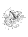
- the centrifugal compressor 1 is a so-called geared compressor including a speed increasing mechanism 2.
- the speed increasing mechanism 2 includes a gear 4 that is rotationally driven by a driving source (not shown) and covered with an exterior portion 3.
- the gear 4 is meshed with a pinion 5 that is a sufficiently smaller gear than the gear 4.
- the pinion 5 is fixed to the central portion in the longitudinal direction of the pinion shaft 6 rotatably supported by the bearing 7.
- the pinion shaft 6 in this embodiment has impellers 8 and 9 attached to both ends thereof. These impellers 8 and 9 have a cantilever structure with respect to the bearing 7. The impellers 8 and 9 compress and flow the fluid supplied from the upstream flow path (not shown) using the centrifugal force generated by the rotation of the pinion shaft 6.
- the casing 10 is formed with a suction passage 12 for allowing a fluid to flow in from an upstream flow path and a discharge passage 13 for allowing the fluid to flow to the outside. Further, on the outer side of the impellers 8 and 9 in the direction of the axis O, a lid portion 11 is disposed at the center of the internal space of the suction passage 12.
- the impellers 8 and 9, the pinion shaft 6, the lid 11, and the pinion 5 constitute the rotor R of this embodiment.
- the alternate long and short dash line indicates the axis O.
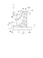
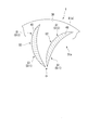
- FIG. 2 shows the meridian surface of the impeller 8.
- the meridian surface of the impeller 8 means a longitudinal section passing through the meridian of the impeller 8 having a circular shape when viewed from the front and the axis of the pinion shaft 6.
- the impeller 8 of the centrifugal compressor 1 includes a disk 30 formed in a disc shape with an axis O as a center, a plurality of blades 40, and a cover 50.
- the centrifugal compressor 1 is a so-called closed type impeller.
- the disk 30 is fixed to the pinion shaft 6 by shrink fitting or the like.
- the plurality of blades 40 are provided so as to protrude from the front side surface (surface on one side in the axis O direction) 31 of the disk 30. Furthermore, these blades 40 are gradually curved from one side in the circumferential direction toward the other side as viewed from the direction of the axis O.
- the cover 50 has an annular shape in front view formed at the front end of the blade 40. Thus, the cover 50 covers the plurality of blades 40 from one side in the axis O direction.
- the disk 30 includes a substantially cylindrical tube portion 32 fitted to the pinion shaft 6.
- the disc 30 includes a disc-shaped disc main body portion 35 extending from the cylindrical portion 32 toward the radially outer side on the rear side in the axial direction.
- the disc main body 35 is formed to be thicker toward the inner side in the radial direction.
- the disc main body portion 35 includes a concave curved surface 31 a that smoothly connects the front side surface 31 and the outer peripheral surface 32 a of the cylindrical portion 32.
- the above-described lid portion 11 covers the end surface 32b of the cylindrical portion 32 and the end surface 6a of the pinion shaft 6 from the outside in the axial direction.
- a plurality of blades 40 are arranged at equal intervals in the circumferential direction of the disk main body 35.
- the blade 40 is gradually tapered from the radially inner side to the radially outer side in a side view.
- the extension dimension (blade height) of the blade 40 based on the front side surface 31 and the curved surface 31a gradually decreases from the radially inner side of the axis O toward the radially outer side.
- the flow path of the impeller 8 includes a front side surface 31, a curved surface 31a, an outer peripheral surface 32a, a surface 40a of the blade 40 facing each other in the circumferential direction, and a wall surface 50a of the cover 50 facing the front side surface 31 and the curved surface 31a. Defined.
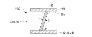
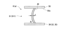
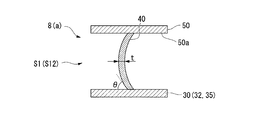
- FIGS. 3A to 3C show a cross section of the blade 40 as viewed from its extending direction (fluid flow direction).
- 3A shows a cross section of the blade 40 taken along the line AA in FIG. 2
- FIG. 3B shows a cross section of the blade 40 taken along the line BB in FIG.
- FIG. 3C shows a cross section of the blade 40 taken along the line CC in FIG.
- the blade 40 is inclined toward one side in the circumferential direction with respect to the front side surface 31 and the curved surface 31a. ing.
- the blade 40 is generally perpendicular to the front side surface 31 and the curved surface 31 a at the center of the impeller 8.
- the inferior angle (the smaller angle) is referred to as a tilt angle ⁇ of the blade 40.
- the tilt angle ⁇ in the region including the inlet 41 and the outlet 42 is set to be relatively smaller than the tilt angle ⁇ of the blade 40 in other regions.
- the plate thickness t is also relatively small compared to the plate thickness t in other regions.
- the rigidity with respect to the bending stress applied from the height direction relative to the blade 40 is relative. It is getting smaller. More specifically, the region on the inlet 41 side of the blade 40 is a first low-rigidity region S11, and the region on the outlet 42 side is a second low-rigidity region S12.
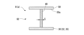
- the tilt angle ⁇ and the plate thickness t are set to be relatively larger than the respective values in the low-rigidity region S1, so The rigidity is relatively large.
- This region is referred to as a high rigidity region S2.
- the low-rigidity region S1 includes a region of approximately 5 to 45% in the fluid flow direction from the inlet 41 or the outlet 42 in the extension region of the flow path of the impeller 8.
- the high-rigidity region S2 is a region from 5 to 100% at the maximum when viewed from the inlet 41 or the outlet 42, and a region from 45 to 55% as the minimum. That is, in the present embodiment, the central region in the extending direction of the blade 40 (fluid flow direction) is the high-rigidity region S2.
- the plate thickness t is relatively large and the tilt angle ⁇ with respect to the disk 30 is set to be relatively large. That is, the plate thickness t and the tilt angle ⁇ change over the entire extension region of the flow path of the impeller 8.
- rigidity can be further increased in a state where the plate thickness t is relatively thin.
- the rigidity of the blade 40 is increased, it is possible to suppress a decrease in compression performance caused by excessively increasing the plate thickness t.
- a relatively low-pressure fluid before being compressed flows through the flow path of the impeller 8.
- the already compressed high-pressure fluid flows on the outside of the cover 50 and the disk 30, the already compressed high-pressure fluid flows. Due to the pressure difference between the high-pressure fluid and the low-pressure fluid, a compressive force may be generated on both sides of the impeller 8 in the direction of the axis O. This compressive force is applied as a bending stress to the blade 40 via the cover 50 and the disk 30.
- the plate thickness t can be made relatively thin, so that the compression performance as the centrifugal compressor 1 can be enhanced.
- the high-rigidity region S2 and the low-rigidity region S1 are formed by changing the tilt angle ⁇ and the plate thickness t of the blade 40 in each part of the blade 40.
- region S1 is not limited to this.
- the high-rigidity region S2 and the low-rigidity region S1 may be formed by changing the curvature in the extending direction of the blade 40 in each part.
- the curvature of the blade 40 when viewed from the direction of the axis O is relatively larger than that in other regions.
- it is set as the low rigidity area
- blade 40 is made into the highly rigid area
- the rigidity of the blade 40 decreases as the curvature when viewed from the direction of the axis O decreases, and increases as the curvature increases. Therefore, according to the above configuration, the high-rigidity region S2 and the low-rigidity region S1 can be formed based on the magnitude of the curvature. Thereby, the rigidity can be increased without increasing the plate thickness t of the blade. In addition, in the low rigidity region S1 corresponding to the inlet 41 and the outlet 42 of the impeller 8, the plate thickness t can be made relatively thin, so that the compression performance as the centrifugal compressor 1 can be enhanced.
- the impeller 8 has been described as having the cover 50. That is, the impeller 8 is a so-called closed type. However, the impeller 8 does not necessarily include the cover 50, and may be configured as a so-called open type.
- the blade 40 is supported in a cantilevered state with respect to the disk 30, so that more aggressive measures against the bending stress based on the pressure difference of the fluid are required. Accordingly, by providing the high-rigidity region S2 and the low-rigidity region S1 as described above on the blade 40, it is possible to obtain a great contribution to the improvement of durability.
- the first low-rigidity region S11, the high-rigidity region S2, and the second low-rigidity region S12 are provided from the inlet 41 side to the outlet 42 side in the extending direction of the blade 40.
- the configuration has been described. However, it is also possible to set only one of the inlet 41 side and the outlet 42 side as the low-rigidity region S1 and all the remaining regions as the high-rigidity region S2.
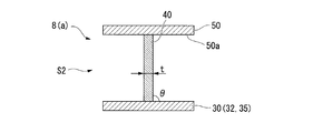
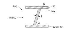
- FIGS. 5A to 5C show a cross section of the blade 40 as viewed from its extending direction (fluid flow direction).
- 5A shows a cross section of the blade 40 taken along the line AA in FIG. 2
- FIG. 5B shows a cross section of the blade 40 taken along the line BB in FIG.
- FIG. 5C shows a cross section of the blade 40 taken along the line CC in FIG.
- symbol is attached
- the end edge 43 on the disk 30 side is opposite to the front side surface 31 and the curved surface 31a. Inclined with a tilt angle ⁇ .
- the edge 44 on the side in contact with the cover 50 is also inclined with respect to the cover 50.
- the blades 40 are smoothly curved from the disk 30 side toward the cover 50 side. More specifically, in the low-rigidity region S1, the blade 40 protrudes in a curved shape from the front side to the rear side in the rotation direction of the pinion shaft 6. Note that the protruding direction of the blade 40 is not limited to the above, and the blade 40 may protrude in a curved shape from the direction opposite to the above, that is, from the rear side to the front side in the rotation direction.
- the blade 40 is generally perpendicular to the disk 30 and the cover 50 as shown in FIG. 5B. Further, in the high rigidity region S2, the plate thickness t of the blade 40 is set relatively thick compared to the plate thickness t in the low rigidity region S1.
- the plate thickness t can be made relatively thin, so that the compression performance as the centrifugal compressor 1 can be enhanced.
- centrifugal compressor 1 the aspect of the centrifugal compressor 1 is not limited to a geared compressor.
- an impeller having sufficient durability and compression performance and a centrifugal compressor can be provided.
Abstract
L'invention concerne une hélice, qui comporte un disque discoïde (30) centré autour d'une ligne axiale (O), et multiples pales (40) disposées en intervalles dans la direction périphérique sur un côté du disque (30) dans la direction de la ligne axiale (O), et formant des trajectoires d'écoulement s'étendant radialement vers l'extérieur à partir d'un côté dans la direction de la ligne axiale (O). Les pales (40) ont une région à faible rigidité, qui comprend l'entrée et/ou la sortie de la zone d'extension des trajectoires d'écoulement, qui a une épaisseur de plaque relativement petite, et qui a un angle d'inclinaison relativement petit par rapport au disque (30), et une région à rigidité élevée, qui est adjacente à la région à faible rigidité, qui a une épaisseur de plaque relativement grande, et qui a un angle d'inclinaison relativement grand par rapport au disque (30).
Priority Applications (1)
| Application Number | Priority Date | Filing Date | Title |
|---|---|---|---|
| US15/562,199 US10947988B2 (en) | 2015-03-30 | 2015-10-26 | Impeller and centrifugal compressor |
Applications Claiming Priority (2)
| Application Number | Priority Date | Filing Date | Title |
|---|---|---|---|
| JP2015-070236 | 2015-03-30 | ||
| JP2015070236A JP6627175B2 (ja) | 2015-03-30 | 2015-03-30 | インペラ、及び遠心圧縮機 |
Publications (1)
| Publication Number | Publication Date |
|---|---|
| WO2016157584A1 true WO2016157584A1 (fr) | 2016-10-06 |
Family
ID=57006869
Family Applications (1)
| Application Number | Title | Priority Date | Filing Date |
|---|---|---|---|
| PCT/JP2015/080075 WO2016157584A1 (fr) | 2015-03-30 | 2015-10-26 | Hélice et compresseur centrifuge |
Country Status (3)
| Country | Link |
|---|---|
| US (1) | US10947988B2 (fr) |
| JP (1) | JP6627175B2 (fr) |
| WO (1) | WO2016157584A1 (fr) |
Families Citing this family (4)
| Publication number | Priority date | Publication date | Assignee | Title |
|---|---|---|---|---|
| JP7221727B2 (ja) | 2019-02-22 | 2023-02-14 | 三菱重工コンプレッサ株式会社 | ギアド圧縮機の位相調整システム、ギアド圧縮機の位相調整治具、及びギアド圧縮機の位相調整方法 |
| CN115335608A (zh) * | 2020-03-30 | 2022-11-11 | 日本电产株式会社 | 叶轮和离心风扇 |
| US11835058B2 (en) * | 2020-04-23 | 2023-12-05 | Mitsubishi Heavy Industries Marine Machinery & Equipment Co., Ltd. | Impeller and centrifugal compressor |
| JP7453896B2 (ja) | 2020-11-12 | 2024-03-21 | 三菱重工コンプレッサ株式会社 | 回転機械のインペラ及び回転機械 |
Citations (9)
| Publication number | Priority date | Publication date | Assignee | Title |
|---|---|---|---|---|
| JPS6385296A (ja) * | 1986-09-26 | 1988-04-15 | Matsushita Electric Ind Co Ltd | 電動送風機 |
| WO1999036701A1 (fr) * | 1998-01-14 | 1999-07-22 | Ebara Corporation | Turbomachines centrifuges |
| DE10200951A1 (de) * | 2002-01-08 | 2003-08-14 | Kern Gmbh Dr | Staubsaugergebläse |
| JP2009243394A (ja) * | 2008-03-31 | 2009-10-22 | Ihi Corp | 遠心圧縮機のインペラ及び過給機 |
| US20110173975A1 (en) * | 2010-01-19 | 2011-07-21 | Ford Global Technologies, Llc | Turbocharger |
| JP2012520412A (ja) * | 2009-03-13 | 2012-09-06 | ターボメカ | スケーラブルなすくい角を有する軸流遠心圧縮機 |
| JP2012219779A (ja) * | 2011-04-13 | 2012-11-12 | Hitachi Plant Technologies Ltd | 羽根車及びそれを有するターボ機械 |
| JP2013104417A (ja) * | 2011-11-17 | 2013-05-30 | Hitachi Plant Technologies Ltd | 遠心式流体機械 |
| JP2014092138A (ja) * | 2012-11-06 | 2014-05-19 | Mitsubishi Heavy Ind Ltd | 遠心回転機械のインペラ、遠心回転機械 |
Family Cites Families (23)
| Publication number | Priority date | Publication date | Assignee | Title |
|---|---|---|---|---|
| US2484554A (en) * | 1945-12-20 | 1949-10-11 | Gen Electric | Centrifugal impeller |
| FR2230229A5 (fr) * | 1973-05-16 | 1974-12-13 | Onera (Off Nat Aerospatiale) | |
| US4093401A (en) * | 1976-04-12 | 1978-06-06 | Sundstrand Corporation | Compressor impeller and method of manufacture |
| US4275988A (en) * | 1978-12-18 | 1981-06-30 | Kalashnikov L F | Axial or worm-type centrifugal impeller pump |
| US4502837A (en) * | 1982-09-30 | 1985-03-05 | General Electric Company | Multi stage centrifugal impeller |
| US4653976A (en) * | 1982-09-30 | 1987-03-31 | General Electric Company | Method of compressing a fluid flow in a multi stage centrifugal impeller |
| GB2224083A (en) * | 1988-10-19 | 1990-04-25 | Rolls Royce Plc | Radial or mixed flow bladed rotors |
| DE69420745T2 (de) * | 1994-06-10 | 2000-04-27 | Ebara Corp | Zentrifugal-oder halbaxialturbomaschinen |
| JPH09112286A (ja) | 1995-10-24 | 1997-04-28 | Mitsubishi Heavy Ind Ltd | 遠心型流体機械の羽根車 |
| US5730582A (en) * | 1997-01-15 | 1998-03-24 | Essex Turbine Ltd. | Impeller for radial flow devices |
| CN1112519C (zh) | 1998-01-14 | 2003-06-25 | 株式会社荏原制作所 | 叶轮和离心式透平机械 |
| ES2160389T3 (es) * | 1998-12-18 | 2001-11-01 | Lothar Reckert | Rodete para sopladores radiales. |
| US6419450B1 (en) * | 2001-05-21 | 2002-07-16 | Grundfos Pumps Manufacturing Corporation | Variable width pump impeller |
| JP3861008B2 (ja) * | 2002-01-10 | 2006-12-20 | 三菱重工業株式会社 | ターボファン及びそれを備えた空気調和装置 |
| JP4545009B2 (ja) * | 2004-03-23 | 2010-09-15 | 三菱重工業株式会社 | 遠心圧縮機 |
| WO2007033274A2 (fr) * | 2005-09-13 | 2007-03-22 | Ingersoll-Rand Company | Impulseur pour compresseur centrifuge |
| US8308420B2 (en) * | 2007-08-03 | 2012-11-13 | Hitachi Plant Technologies, Ltd. | Centrifugal compressor, impeller and operating method of the same |
| US8475131B2 (en) * | 2008-11-21 | 2013-07-02 | Hitachi Plant Technologies, Ltd. | Centrifugal compressor |
| US8668446B2 (en) * | 2010-08-31 | 2014-03-11 | General Electric Company | Supersonic compressor rotor and method of assembling same |
| US8864454B2 (en) * | 2010-10-28 | 2014-10-21 | General Electric Company | System and method of assembling a supersonic compressor system including a supersonic compressor rotor and a compressor assembly |
| JP5803305B2 (ja) * | 2011-06-10 | 2015-11-04 | 株式会社Ihi | 遠心圧縮機 |
| JP2013040587A (ja) * | 2011-08-18 | 2013-02-28 | Ihi Corp | 遠心圧縮機 |
| CN203770209U (zh) | 2014-02-13 | 2014-08-13 | 沈阳斯特机械制造有限公司 | 一种离心压缩机的闭式叶轮 |
-
2015
- 2015-03-30 JP JP2015070236A patent/JP6627175B2/ja active Active
- 2015-10-26 WO PCT/JP2015/080075 patent/WO2016157584A1/fr active Application Filing
- 2015-10-26 US US15/562,199 patent/US10947988B2/en active Active
Patent Citations (9)
| Publication number | Priority date | Publication date | Assignee | Title |
|---|---|---|---|---|
| JPS6385296A (ja) * | 1986-09-26 | 1988-04-15 | Matsushita Electric Ind Co Ltd | 電動送風機 |
| WO1999036701A1 (fr) * | 1998-01-14 | 1999-07-22 | Ebara Corporation | Turbomachines centrifuges |
| DE10200951A1 (de) * | 2002-01-08 | 2003-08-14 | Kern Gmbh Dr | Staubsaugergebläse |
| JP2009243394A (ja) * | 2008-03-31 | 2009-10-22 | Ihi Corp | 遠心圧縮機のインペラ及び過給機 |
| JP2012520412A (ja) * | 2009-03-13 | 2012-09-06 | ターボメカ | スケーラブルなすくい角を有する軸流遠心圧縮機 |
| US20110173975A1 (en) * | 2010-01-19 | 2011-07-21 | Ford Global Technologies, Llc | Turbocharger |
| JP2012219779A (ja) * | 2011-04-13 | 2012-11-12 | Hitachi Plant Technologies Ltd | 羽根車及びそれを有するターボ機械 |
| JP2013104417A (ja) * | 2011-11-17 | 2013-05-30 | Hitachi Plant Technologies Ltd | 遠心式流体機械 |
| JP2014092138A (ja) * | 2012-11-06 | 2014-05-19 | Mitsubishi Heavy Ind Ltd | 遠心回転機械のインペラ、遠心回転機械 |
Also Published As
| Publication number | Publication date |
|---|---|
| US10947988B2 (en) | 2021-03-16 |
| JP6627175B2 (ja) | 2020-01-08 |
| JP2016191311A (ja) | 2016-11-10 |
| US20180058468A1 (en) | 2018-03-01 |
Similar Documents
| Publication | Publication Date | Title |
|---|---|---|
| US9874219B2 (en) | Impeller and fluid machine | |
| WO2016157584A1 (fr) | Hélice et compresseur centrifuge | |
| JP5709898B2 (ja) | 回転機械 | |
| WO2010098032A1 (fr) | Carter d'aspiration et machine hydraulique | |
| WO2012033192A1 (fr) | Structure d'étanchéité et compresseur centrifuge | |
| JP2016031064A (ja) | 多段ポンプ | |
| JP2011140917A (ja) | 両吸込ポンプ | |
| WO2017170105A1 (fr) | Compresseur centrifuge | |
| WO2014122819A1 (fr) | Compresseur centrifuge | |
| CN105275883B (zh) | 压缩机和压缩机的制造方法 | |
| CN111448396B (zh) | 可变静叶片、及压缩机 | |
| WO2018155546A1 (fr) | Compresseur centrifuge | |
| JP5405884B2 (ja) | ターボ機械のバレル型ケーシングとヘッドカバーの取付構造 | |
| JP6336134B2 (ja) | 遠心圧縮機のケーシング、及び、遠心圧縮機 | |
| US10859092B2 (en) | Impeller and rotating machine | |
| US11401944B2 (en) | Impeller and centrifugal compressor | |
| WO2017150554A1 (fr) | Machine tournante centrifuge | |
| CN111608952B (zh) | 叶轮以及旋转机械 | |
| JP2007162483A (ja) | 過流ポンプ | |
| JP6168705B2 (ja) | 遠心式圧縮機のインペラ | |
| JP6745331B2 (ja) | 回転機械、ターボチャージャ | |
| US20180142653A1 (en) | Fuel pump | |
| JP6099988B2 (ja) | ウォータポンプ | |
| WO2018179173A1 (fr) | Hélice et compresseur centrifuge | |
| JP2020045805A (ja) | 液体ポンプ |
Legal Events
| Date | Code | Title | Description |
|---|---|---|---|
| 121 | Ep: the epo has been informed by wipo that ep was designated in this application |
Ref document number: 15887726 Country of ref document: EP Kind code of ref document: A1 |
|
| WWE | Wipo information: entry into national phase |
Ref document number: 15562199 Country of ref document: US |
|
| NENP | Non-entry into the national phase |
Ref country code: DE |
|
| 122 | Ep: pct application non-entry in european phase |
Ref document number: 15887726 Country of ref document: EP Kind code of ref document: A1 |