WO2016157584A1 - Impeller and centrifugal compressor - Google Patents
Impeller and centrifugal compressor Download PDFInfo
- Publication number
- WO2016157584A1 WO2016157584A1 PCT/JP2015/080075 JP2015080075W WO2016157584A1 WO 2016157584 A1 WO2016157584 A1 WO 2016157584A1 JP 2015080075 W JP2015080075 W JP 2015080075W WO 2016157584 A1 WO2016157584 A1 WO 2016157584A1
- Authority
- WO
- WIPO (PCT)
- Prior art keywords
- impeller
- region
- rigidity region
- rigidity
- low
- Prior art date
Links
Images
Classifications
-
- F—MECHANICAL ENGINEERING; LIGHTING; HEATING; WEAPONS; BLASTING
- F04—POSITIVE - DISPLACEMENT MACHINES FOR LIQUIDS; PUMPS FOR LIQUIDS OR ELASTIC FLUIDS
- F04D—NON-POSITIVE-DISPLACEMENT PUMPS
- F04D29/00—Details, component parts, or accessories
- F04D29/26—Rotors specially for elastic fluids
- F04D29/28—Rotors specially for elastic fluids for centrifugal or helico-centrifugal pumps for radial-flow or helico-centrifugal pumps
- F04D29/30—Vanes
-
- F—MECHANICAL ENGINEERING; LIGHTING; HEATING; WEAPONS; BLASTING
- F04—POSITIVE - DISPLACEMENT MACHINES FOR LIQUIDS; PUMPS FOR LIQUIDS OR ELASTIC FLUIDS
- F04D—NON-POSITIVE-DISPLACEMENT PUMPS
- F04D29/00—Details, component parts, or accessories
- F04D29/26—Rotors specially for elastic fluids
- F04D29/28—Rotors specially for elastic fluids for centrifugal or helico-centrifugal pumps for radial-flow or helico-centrifugal pumps
- F04D29/284—Rotors specially for elastic fluids for centrifugal or helico-centrifugal pumps for radial-flow or helico-centrifugal pumps for compressors
-
- F—MECHANICAL ENGINEERING; LIGHTING; HEATING; WEAPONS; BLASTING
- F04—POSITIVE - DISPLACEMENT MACHINES FOR LIQUIDS; PUMPS FOR LIQUIDS OR ELASTIC FLUIDS
- F04D—NON-POSITIVE-DISPLACEMENT PUMPS
- F04D29/00—Details, component parts, or accessories
- F04D29/05—Shafts or bearings, or assemblies thereof, specially adapted for elastic fluid pumps
- F04D29/053—Shafts
-
- F—MECHANICAL ENGINEERING; LIGHTING; HEATING; WEAPONS; BLASTING
- F04—POSITIVE - DISPLACEMENT MACHINES FOR LIQUIDS; PUMPS FOR LIQUIDS OR ELASTIC FLUIDS
- F04D—NON-POSITIVE-DISPLACEMENT PUMPS
- F04D29/00—Details, component parts, or accessories
- F04D29/40—Casings; Connections of working fluid
- F04D29/42—Casings; Connections of working fluid for radial or helico-centrifugal pumps
- F04D29/4206—Casings; Connections of working fluid for radial or helico-centrifugal pumps especially adapted for elastic fluid pumps
-
- F—MECHANICAL ENGINEERING; LIGHTING; HEATING; WEAPONS; BLASTING
- F05—INDEXING SCHEMES RELATING TO ENGINES OR PUMPS IN VARIOUS SUBCLASSES OF CLASSES F01-F04
- F05D—INDEXING SCHEME FOR ASPECTS RELATING TO NON-POSITIVE-DISPLACEMENT MACHINES OR ENGINES, GAS-TURBINES OR JET-PROPULSION PLANTS
- F05D2250/00—Geometry
- F05D2250/70—Shape
Definitions
- the present invention relates to an impeller and a centrifugal compressor including the same.
- This application claims priority based on Japanese Patent Application No. 2015-070236 for which it applied on March 30, 2015, and uses the description.
- a centrifugal compressor includes an impeller having a plurality of blades extending radially about a rotation axis, and a casing that defines a flow path between the impeller and the impeller by covering the impeller from the outside. .
- the flow path sucks an external fluid into the casing by the rotation of the impeller, applies pressure to the fluid while flowing through the flow path, and discharges the fluid from the casing outlet in a high pressure state.
- Patent Document 1 As an example of such a technique, one described in Patent Document 1 below is known.
- the thickness of at least one of the inlet side and the outlet side of the impeller is formed thick.
- the present invention has been made in consideration of the above circumstances, and an object thereof is to provide an impeller and a centrifugal compressor having sufficient rigidity and compression performance.
- the impeller includes a disk having a disk shape centered on the axis, and a plurality of impellers are provided on one side of the disk in the axial direction with a circumferential interval.
- a blade defining a flow path extending radially outward from the side, and the blade includes at least one of an inlet and an outlet of an extension region of the flow path, and has a relatively small plate thickness,
- a low-rigidity region having a relatively small tilt angle with respect to the disk, and a high-rigidity region adjacent to the low-rigidity region and having a relatively large plate thickness and a relatively large tilt angle with respect to the disk.
- the plate thickness is relatively large and the tilt angle with respect to the disk is set relatively large. That is, the plate thickness and the tilt angle change over the entire extension region of the flow path.
- the rigidity can be further increased in a state where the plate thickness is relatively thin as compared with the configuration in which only the plate thickness is increased.
- a rigidity difference is generated between the high rigidity region and the low rigidity region. Due to this difference in rigidity, even if a bending stress is applied to the blade, most of the bending stress can be received in the high rigidity region.
- the high-rigidity region may be a central portion between the inlet and the outlet in the extension region of the flow path.
- the rigidity of the central portion in the extending region of the flow path can be increased. Thereby, most of the bending stress applied to the blade can be received at the central portion.
- the curvature in the radial direction of the axis in the low rigidity region, is relatively small, and in the high rigidity region, The curvature in the radial direction of the axis may be configured to be relatively large.
- the rigidity of the blade against bending stress decreases as the curvature decreases, and increases as the curvature increases. Therefore, according to the above configuration, the high rigidity region and the low rigidity region can be formed based on the magnitude of the curvature. Thereby, the rigidity can be increased without increasing the plate thickness of the blade.
- the impeller according to any one of the first to third aspects may have a cover that covers the plurality of blades from one side in the axial direction.
- the blade is supported from both sides in the axial direction by the disk and the cover. Thereby, the rigidity of the blade can be further increased.
- the centrifugal compressor covers the rotating shaft that rotates around the axis, the impeller according to any one of the above-described aspects, attached to the rotating shaft, and covers the impeller from the outside.
- a casing A casing.
- the impeller includes a disk having a disk shape centered on the axis, and a plurality of the impellers are provided on one side in the axial direction of the disk at intervals in the circumferential direction. And a blade defining a flow path extending radially outward from the first low rigidity including an inlet of an extension region of the flow path and having a relatively small tilt angle with respect to the disk An area, a high-rigidity area adjacent to the first low-rigidity area and having a relatively large tilt angle with respect to the disk, an outlet of the extension area of the flow path, adjacent to the high-rigidity area, A second low-rigidity region having a relatively small tilt angle with respect to the disk.
- a rigidity difference is generated between the high rigidity region, the first low rigidity region, and the second low rigidity region. Due to this difference in rigidity, even if a bending stress is applied to the blade, most of the bending stress can be received in the high rigidity region.
- the impeller according to the sixth aspect may have a cover that covers the plurality of blades from one side in the axial direction.
- the blade is supported from both sides in the axial direction by the disk and the cover. Thereby, the rigidity of the blade can be further increased.
- the centrifugal compressor according to the sixth or seventh aspect according to any one of the aspects attached to the rotary shaft and the rotary shaft rotating around the axis.
- the impeller which concerns, and the casing which covers the said impeller from the outer side are provided.
- an impeller having sufficient rigidity and compression performance, and a centrifugal compressor can be provided.
- FIG. 3 is a cross-sectional view of the impeller according to the first embodiment of the present invention, and is a cross-sectional view taken along line AA of FIG.
- FIG. 3 is a cross-sectional view of the impeller according to the first embodiment of the present invention, and is a cross-sectional view taken along the line BB of FIG.
- FIG. 3 is a cross-sectional view of the impeller according to the first embodiment of the present invention, and is a cross-sectional view taken along the line CC of FIG.
- FIG. 3 is a cross-sectional view of an impeller according to a second embodiment of the present invention, which is a cross-sectional view taken along line AA of FIG.
- FIG. 4 is a cross-sectional view of an impeller according to a second embodiment of the present invention, which is a cross-sectional view taken along line BB of FIG.
- FIG. 4 is a cross-sectional view of an impeller according to a second embodiment of the present invention, which is a cross-sectional view taken along the line CC of FIG.
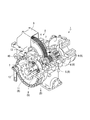
- the centrifugal compressor 1 is a so-called geared compressor including a speed increasing mechanism 2.
- the speed increasing mechanism 2 includes a gear 4 that is rotationally driven by a driving source (not shown) and covered with an exterior portion 3.
- the gear 4 is meshed with a pinion 5 that is a sufficiently smaller gear than the gear 4.
- the pinion 5 is fixed to the central portion in the longitudinal direction of the pinion shaft 6 rotatably supported by the bearing 7.
- the pinion shaft 6 in this embodiment has impellers 8 and 9 attached to both ends thereof. These impellers 8 and 9 have a cantilever structure with respect to the bearing 7. The impellers 8 and 9 compress and flow the fluid supplied from the upstream flow path (not shown) using the centrifugal force generated by the rotation of the pinion shaft 6.
- the casing 10 is formed with a suction passage 12 for allowing a fluid to flow in from an upstream flow path and a discharge passage 13 for allowing the fluid to flow to the outside. Further, on the outer side of the impellers 8 and 9 in the direction of the axis O, a lid portion 11 is disposed at the center of the internal space of the suction passage 12.
- the impellers 8 and 9, the pinion shaft 6, the lid 11, and the pinion 5 constitute the rotor R of this embodiment.
- the alternate long and short dash line indicates the axis O.
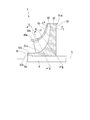
- FIG. 2 shows the meridian surface of the impeller 8.
- the meridian surface of the impeller 8 means a longitudinal section passing through the meridian of the impeller 8 having a circular shape when viewed from the front and the axis of the pinion shaft 6.
- the impeller 8 of the centrifugal compressor 1 includes a disk 30 formed in a disc shape with an axis O as a center, a plurality of blades 40, and a cover 50.
- the centrifugal compressor 1 is a so-called closed type impeller.
- the disk 30 is fixed to the pinion shaft 6 by shrink fitting or the like.
- the plurality of blades 40 are provided so as to protrude from the front side surface (surface on one side in the axis O direction) 31 of the disk 30. Furthermore, these blades 40 are gradually curved from one side in the circumferential direction toward the other side as viewed from the direction of the axis O.
- the cover 50 has an annular shape in front view formed at the front end of the blade 40. Thus, the cover 50 covers the plurality of blades 40 from one side in the axis O direction.
- the disk 30 includes a substantially cylindrical tube portion 32 fitted to the pinion shaft 6.
- the disc 30 includes a disc-shaped disc main body portion 35 extending from the cylindrical portion 32 toward the radially outer side on the rear side in the axial direction.
- the disc main body 35 is formed to be thicker toward the inner side in the radial direction.
- the disc main body portion 35 includes a concave curved surface 31 a that smoothly connects the front side surface 31 and the outer peripheral surface 32 a of the cylindrical portion 32.
- the above-described lid portion 11 covers the end surface 32b of the cylindrical portion 32 and the end surface 6a of the pinion shaft 6 from the outside in the axial direction.
- a plurality of blades 40 are arranged at equal intervals in the circumferential direction of the disk main body 35.
- the blade 40 is gradually tapered from the radially inner side to the radially outer side in a side view.
- the extension dimension (blade height) of the blade 40 based on the front side surface 31 and the curved surface 31a gradually decreases from the radially inner side of the axis O toward the radially outer side.
- the flow path of the impeller 8 includes a front side surface 31, a curved surface 31a, an outer peripheral surface 32a, a surface 40a of the blade 40 facing each other in the circumferential direction, and a wall surface 50a of the cover 50 facing the front side surface 31 and the curved surface 31a. Defined.
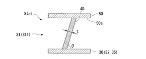
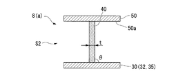
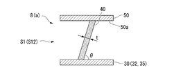
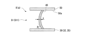
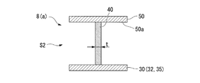
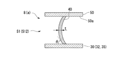
- FIGS. 3A to 3C show a cross section of the blade 40 as viewed from its extending direction (fluid flow direction).
- 3A shows a cross section of the blade 40 taken along the line AA in FIG. 2
- FIG. 3B shows a cross section of the blade 40 taken along the line BB in FIG.
- FIG. 3C shows a cross section of the blade 40 taken along the line CC in FIG.
- the blade 40 is inclined toward one side in the circumferential direction with respect to the front side surface 31 and the curved surface 31a. ing.
- the blade 40 is generally perpendicular to the front side surface 31 and the curved surface 31 a at the center of the impeller 8.
- the inferior angle (the smaller angle) is referred to as a tilt angle ⁇ of the blade 40.
- the tilt angle ⁇ in the region including the inlet 41 and the outlet 42 is set to be relatively smaller than the tilt angle ⁇ of the blade 40 in other regions.
- the plate thickness t is also relatively small compared to the plate thickness t in other regions.
- the rigidity with respect to the bending stress applied from the height direction relative to the blade 40 is relative. It is getting smaller. More specifically, the region on the inlet 41 side of the blade 40 is a first low-rigidity region S11, and the region on the outlet 42 side is a second low-rigidity region S12.
- the tilt angle ⁇ and the plate thickness t are set to be relatively larger than the respective values in the low-rigidity region S1, so The rigidity is relatively large.
- This region is referred to as a high rigidity region S2.
- the low-rigidity region S1 includes a region of approximately 5 to 45% in the fluid flow direction from the inlet 41 or the outlet 42 in the extension region of the flow path of the impeller 8.
- the high-rigidity region S2 is a region from 5 to 100% at the maximum when viewed from the inlet 41 or the outlet 42, and a region from 45 to 55% as the minimum. That is, in the present embodiment, the central region in the extending direction of the blade 40 (fluid flow direction) is the high-rigidity region S2.
- the plate thickness t is relatively large and the tilt angle ⁇ with respect to the disk 30 is set to be relatively large. That is, the plate thickness t and the tilt angle ⁇ change over the entire extension region of the flow path of the impeller 8.
- rigidity can be further increased in a state where the plate thickness t is relatively thin.
- the rigidity of the blade 40 is increased, it is possible to suppress a decrease in compression performance caused by excessively increasing the plate thickness t.
- a relatively low-pressure fluid before being compressed flows through the flow path of the impeller 8.
- the already compressed high-pressure fluid flows on the outside of the cover 50 and the disk 30, the already compressed high-pressure fluid flows. Due to the pressure difference between the high-pressure fluid and the low-pressure fluid, a compressive force may be generated on both sides of the impeller 8 in the direction of the axis O. This compressive force is applied as a bending stress to the blade 40 via the cover 50 and the disk 30.
- the plate thickness t can be made relatively thin, so that the compression performance as the centrifugal compressor 1 can be enhanced.
- the high-rigidity region S2 and the low-rigidity region S1 are formed by changing the tilt angle ⁇ and the plate thickness t of the blade 40 in each part of the blade 40.
- region S1 is not limited to this.
- the high-rigidity region S2 and the low-rigidity region S1 may be formed by changing the curvature in the extending direction of the blade 40 in each part.
- the curvature of the blade 40 when viewed from the direction of the axis O is relatively larger than that in other regions.
- it is set as the low rigidity area
- blade 40 is made into the highly rigid area
- the rigidity of the blade 40 decreases as the curvature when viewed from the direction of the axis O decreases, and increases as the curvature increases. Therefore, according to the above configuration, the high-rigidity region S2 and the low-rigidity region S1 can be formed based on the magnitude of the curvature. Thereby, the rigidity can be increased without increasing the plate thickness t of the blade. In addition, in the low rigidity region S1 corresponding to the inlet 41 and the outlet 42 of the impeller 8, the plate thickness t can be made relatively thin, so that the compression performance as the centrifugal compressor 1 can be enhanced.
- the impeller 8 has been described as having the cover 50. That is, the impeller 8 is a so-called closed type. However, the impeller 8 does not necessarily include the cover 50, and may be configured as a so-called open type.
- the blade 40 is supported in a cantilevered state with respect to the disk 30, so that more aggressive measures against the bending stress based on the pressure difference of the fluid are required. Accordingly, by providing the high-rigidity region S2 and the low-rigidity region S1 as described above on the blade 40, it is possible to obtain a great contribution to the improvement of durability.
- the first low-rigidity region S11, the high-rigidity region S2, and the second low-rigidity region S12 are provided from the inlet 41 side to the outlet 42 side in the extending direction of the blade 40.
- the configuration has been described. However, it is also possible to set only one of the inlet 41 side and the outlet 42 side as the low-rigidity region S1 and all the remaining regions as the high-rigidity region S2.
- FIGS. 5A to 5C show a cross section of the blade 40 as viewed from its extending direction (fluid flow direction).
- 5A shows a cross section of the blade 40 taken along the line AA in FIG. 2
- FIG. 5B shows a cross section of the blade 40 taken along the line BB in FIG.
- FIG. 5C shows a cross section of the blade 40 taken along the line CC in FIG.
- symbol is attached
- the end edge 43 on the disk 30 side is opposite to the front side surface 31 and the curved surface 31a. Inclined with a tilt angle ⁇ .
- the edge 44 on the side in contact with the cover 50 is also inclined with respect to the cover 50.
- the blades 40 are smoothly curved from the disk 30 side toward the cover 50 side. More specifically, in the low-rigidity region S1, the blade 40 protrudes in a curved shape from the front side to the rear side in the rotation direction of the pinion shaft 6. Note that the protruding direction of the blade 40 is not limited to the above, and the blade 40 may protrude in a curved shape from the direction opposite to the above, that is, from the rear side to the front side in the rotation direction.
- the blade 40 is generally perpendicular to the disk 30 and the cover 50 as shown in FIG. 5B. Further, in the high rigidity region S2, the plate thickness t of the blade 40 is set relatively thick compared to the plate thickness t in the low rigidity region S1.
- the plate thickness t can be made relatively thin, so that the compression performance as the centrifugal compressor 1 can be enhanced.
- centrifugal compressor 1 the aspect of the centrifugal compressor 1 is not limited to a geared compressor.
- an impeller having sufficient durability and compression performance and a centrifugal compressor can be provided.
Abstract
An impeller equipped with a disc-shaped disc 30 centered around an axial line O, and multiple blades 40 provided at intervals in the circumferential direction on one side of the disc 30 in the axial line O direction and forming flow paths extending radially outward from one side in the axial line O direction. The blades 40 have a low-rigidity region, which includes the inlet and/or the outlet of the extension region of the flow paths, has a relatively small plate thickness, and has a relatively small tilt angle with respect to the disc 30, and a high-rigidity region, which is adjacent to the low-rigidity region, has a relatively large plate thickness, and has a relatively large tilt angle with respect to the disc 30.
Description
本発明は、インペラ、及びこれを備える遠心圧縮機に関する。
本願は、2015年3月30日に出願された特願2015-070236に基づいて優先権を主張し、その記載を援用する。 The present invention relates to an impeller and a centrifugal compressor including the same.
This application claims priority based on Japanese Patent Application No. 2015-070236 for which it applied on March 30, 2015, and uses the description.
一般的に遠心圧縮機は、回転軸を中心として放射状に延びる複数のブレードを有するインペラと、このインペラを外側から覆うことでインペラとの間で流路を画成するケーシングと、を備えている。この流路は、インペラの回転によってケーシング内に外部の流体を吸引するとともに、流路中を流通する間に流体に圧力を加えてケーシング出口から高圧状態で吐出する。
Generally, a centrifugal compressor includes an impeller having a plurality of blades extending radially about a rotation axis, and a casing that defines a flow path between the impeller and the impeller by covering the impeller from the outside. . The flow path sucks an external fluid into the casing by the rotation of the impeller, applies pressure to the fluid while flowing through the flow path, and discharges the fluid from the casing outlet in a high pressure state.
上記のような遠心圧縮機では、特にインペラの前後で高圧の流体と低圧の流体とが混在している。これら流体の圧力差に起因して、インペラ上のブレードに曲げ応力が付加されることが知られている。
In the centrifugal compressor as described above, a high pressure fluid and a low pressure fluid are mixed before and after the impeller. It is known that bending stress is applied to the blade on the impeller due to the pressure difference between these fluids.
そこで、上記の曲げ応力に対する剛性を高めることを目的として、これまでに種々の技術が提唱されている。このような技術の一例として、下記特許文献1に記載されたものが知られている。特許文献1に記載された遠心圧縮機では、インペラの入口側、及び出口側の少なくとも一方における肉厚が厚く形成されている。
Therefore, various techniques have been proposed so far for the purpose of increasing the rigidity against the bending stress. As an example of such a technique, one described in Patent Document 1 below is known. In the centrifugal compressor described in Patent Document 1, the thickness of at least one of the inlet side and the outlet side of the impeller is formed thick.
ところで、遠心圧縮機では、ブレードの肉厚を増してしまうと、圧縮性能に影響が及ぶことが知られている。特に、インペラの出口側におけるブレードの肉厚を増加した場合には、圧縮性能に顕著な影響が及んでしまう。また,インペラの重量増加に起因して,振動特性にも影響が及ぶ。したがって、上記特許文献1の遠心圧縮機、及びインペラには改善の余地がある。
Incidentally, it is known that in a centrifugal compressor, if the blade thickness is increased, the compression performance is affected. In particular, when the thickness of the blade on the outlet side of the impeller is increased, the compression performance is significantly affected. In addition, the vibration characteristics are affected by the weight increase of the impeller. Therefore, there is room for improvement in the centrifugal compressor and the impeller of Patent Document 1.
本発明は、上記の事情を考慮してなされたものであり、十分な剛性と圧縮性能とを備えるインペラ、及び遠心圧縮機を提供することを目的とする。
The present invention has been made in consideration of the above circumstances, and an object thereof is to provide an impeller and a centrifugal compressor having sufficient rigidity and compression performance.
本発明の第一の態様によれば、インペラは、軸線を中心とした円盤状をなすディスクと、該ディスクの前記軸線方向一方側に、周方向に間隔をあけて複数設けられて軸線方向一方側から径方向外側に向かって延びる流路を画成するブレードと、を備え、前記ブレードは、前記流路の延在領域の入口及び出口の少なくとも一方を含み、板厚が相対的に小さく、かつ前記ディスクに対する倒れ角度が相対的に小さい低剛性領域と、該低剛性領域に隣接し、板厚が相対的に大きく、かつ、前記ディスクに対する倒れ角度が相対的に大きい高剛性領域と、を有する。
According to the first aspect of the present invention, the impeller includes a disk having a disk shape centered on the axis, and a plurality of impellers are provided on one side of the disk in the axial direction with a circumferential interval. A blade defining a flow path extending radially outward from the side, and the blade includes at least one of an inlet and an outlet of an extension region of the flow path, and has a relatively small plate thickness, A low-rigidity region having a relatively small tilt angle with respect to the disk, and a high-rigidity region adjacent to the low-rigidity region and having a relatively large plate thickness and a relatively large tilt angle with respect to the disk. Have.
上述のような構成によれば、ブレードの高剛性領域では、板厚が相対的に大きく、かつ、ディスクに対する倒れ角度が相対的に大きく設定されている。すなわち、板厚と倒れ角度とが、流路の延在領域全体にわたって変化している。これにより、例えば板厚のみを増加させる構成に比べて、板厚を比較的に薄くした状態で、剛性をさらに高めることができる。さらに、上記のような構成によれば、高剛性領域と、低剛性領域との間に剛性差が生じる。この剛性差により、ブレードに対して曲げ応力が付加された場合であっても、曲げ応力の大部分を高剛性領域で受け止めることができる。
According to the configuration as described above, in the high rigidity region of the blade, the plate thickness is relatively large and the tilt angle with respect to the disk is set relatively large. That is, the plate thickness and the tilt angle change over the entire extension region of the flow path. Thereby, for example, the rigidity can be further increased in a state where the plate thickness is relatively thin as compared with the configuration in which only the plate thickness is increased. Furthermore, according to the configuration as described above, a rigidity difference is generated between the high rigidity region and the low rigidity region. Due to this difference in rigidity, even if a bending stress is applied to the blade, most of the bending stress can be received in the high rigidity region.
本発明の第二の態様によれば、上記第一の態様に係るインペラでは、前記高剛性領域は、前記流路の延在領域における前記入口及び前記出口の間の中央部であってもよい。
According to the second aspect of the present invention, in the impeller according to the first aspect, the high-rigidity region may be a central portion between the inlet and the outlet in the extension region of the flow path. .
上述のような構成によれば、流路の延在領域における中央部の剛性を高めることができる。これにより、ブレードに付加される曲げ応力の大部分を該中央部で受け止めることができる。
According to the configuration as described above, the rigidity of the central portion in the extending region of the flow path can be increased. Thereby, most of the bending stress applied to the blade can be received at the central portion.
本発明の第三の態様によれば、上記第一又は第二の態様に係るインペラでは、前記低剛性領域では、前記軸線の径方向における曲率が相対的に小さく、前記高剛性領域では、前記軸線の径方向における曲率が相対的に大きく構成されていてもよい。
According to the third aspect of the present invention, in the impeller according to the first or second aspect, in the low rigidity region, the curvature in the radial direction of the axis is relatively small, and in the high rigidity region, The curvature in the radial direction of the axis may be configured to be relatively large.
ここで、ブレードの曲げ応力に対する剛性は、曲率が小さいほど低下し、曲率が大きいほど増加する。したがって、上記のような構成によれば、曲率の大小に基づいて高剛性領域と低剛性領域とを形成することができる。これにより、ブレードの板厚を増加させることなく、剛性を高めることができる。
Here, the rigidity of the blade against bending stress decreases as the curvature decreases, and increases as the curvature increases. Therefore, according to the above configuration, the high rigidity region and the low rigidity region can be formed based on the magnitude of the curvature. Thereby, the rigidity can be increased without increasing the plate thickness of the blade.
本発明の第四の態様によれば、上記第一から第三のいずれか一態様に係るインペラは、複数の前記ブレードを、軸線方向一方側から覆うカバーを有してもよい。
According to the fourth aspect of the present invention, the impeller according to any one of the first to third aspects may have a cover that covers the plurality of blades from one side in the axial direction.
上述のような構成によれば、ブレードがディスクとカバーとによって軸線方向の両側から支持される。これにより、ブレードの剛性をさらに高めることができる。
According to the above configuration, the blade is supported from both sides in the axial direction by the disk and the cover. Thereby, the rigidity of the blade can be further increased.
本発明の第五の態様によれば、遠心圧縮機は、前記軸線回りに回転する回転軸と、前記回転軸に取り付けられた、上記いずれか一態様に係るインペラと、前記インペラを外側から覆うケーシングと、を備える。
According to the fifth aspect of the present invention, the centrifugal compressor covers the rotating shaft that rotates around the axis, the impeller according to any one of the above-described aspects, attached to the rotating shaft, and covers the impeller from the outside. A casing.
上述のような構成によれば、十分な耐久性と圧縮性能とを備える遠心圧縮機を提供することができる。
According to the above configuration, a centrifugal compressor having sufficient durability and compression performance can be provided.
本発明の第六の態様によれば、インペラは、軸線を中心として円盤状をなすディスクと、該ディスクの前記軸線方向一方側に、周方向に間隔をあけて複数設けられて軸線方向一方側から径方向外側に向かって延びる流路を画成するブレードと、を備え、前記ブレードは、前記流路の延在領域の入口を含み、前記ディスクに対する倒れ角度が相対的に小さい第一低剛性領域と、該第一低剛性領域に隣接するとともに、前記ディスクに対する倒れ角度が相対的に大きい高剛性領域と、該高剛性領域に隣接し、かつ前記流路の延在領域の出口を含み、前記ディスクに対する倒れ角度が相対的に小さい第二低剛性領域と、を有する。
According to the sixth aspect of the present invention, the impeller includes a disk having a disk shape centered on the axis, and a plurality of the impellers are provided on one side in the axial direction of the disk at intervals in the circumferential direction. And a blade defining a flow path extending radially outward from the first low rigidity including an inlet of an extension region of the flow path and having a relatively small tilt angle with respect to the disk An area, a high-rigidity area adjacent to the first low-rigidity area and having a relatively large tilt angle with respect to the disk, an outlet of the extension area of the flow path, adjacent to the high-rigidity area, A second low-rigidity region having a relatively small tilt angle with respect to the disk.
上述のような構成によれば、高剛性領域と、第一低剛性領域、及び第二低剛性領域との間に剛性差が生じる。この剛性差により、ブレードに対して曲げ応力が付加された場合であっても、曲げ応力の大部分を高剛性領域で受け止めることができる。
According to the above configuration, a rigidity difference is generated between the high rigidity region, the first low rigidity region, and the second low rigidity region. Due to this difference in rigidity, even if a bending stress is applied to the blade, most of the bending stress can be received in the high rigidity region.
本発明の第七の態様によれば、上記第六の態様に係るインペラは、複数の前記ブレードを、軸線方向一方側から覆うカバーを有してもよい。
According to the seventh aspect of the present invention, the impeller according to the sixth aspect may have a cover that covers the plurality of blades from one side in the axial direction.
上述のような構成によれば、ブレードがディスクとカバーとによって軸線方向の両側から支持される。これにより、ブレードの剛性をさらに高めることができる。
According to the above configuration, the blade is supported from both sides in the axial direction by the disk and the cover. Thereby, the rigidity of the blade can be further increased.
本発明の第八の態様によれば、上記第六又は第七の態様に係る遠心圧縮機は、前記軸線回りに回転する回転軸と、前記回転軸に取り付けられた上記いずれか1つの態様に係るインペラと、前記インペラを外側から覆うケーシングと、を備える。
According to an eighth aspect of the present invention, there is provided the centrifugal compressor according to the sixth or seventh aspect according to any one of the aspects attached to the rotary shaft and the rotary shaft rotating around the axis. The impeller which concerns, and the casing which covers the said impeller from the outer side are provided.
上述のような構成によれば、十分な耐久性と圧縮性能とを備える遠心圧縮機を提供することができる。
According to the above configuration, a centrifugal compressor having sufficient durability and compression performance can be provided.
上述の構成によれば、十分な剛性と圧縮性能とを備えるインペラ、及び遠心圧縮機を提供することができる。
According to the above configuration, an impeller having sufficient rigidity and compression performance, and a centrifugal compressor can be provided.
[第一実施形態]
以下、本発明の第一実施形態について図面を参照して説明する。
図1に示すように、遠心圧縮機1は、増速機構2を内蔵したいわゆるギアド圧縮機である。増速機構2は、駆動源(図示せず)により回転駆動され外装部3によって覆われた歯車4を備えている。歯車4には、歯車4よりも十分に小さい歯車であるピニオン5が噛み合わされている。このピニオン5は、軸受7により回転可能に支持されたピニオンシャフト6の長手方向の中央部に固定されている。 [First embodiment]
Hereinafter, a first embodiment of the present invention will be described with reference to the drawings.
As shown in FIG. 1, thecentrifugal compressor 1 is a so-called geared compressor including a speed increasing mechanism 2. The speed increasing mechanism 2 includes a gear 4 that is rotationally driven by a driving source (not shown) and covered with an exterior portion 3. The gear 4 is meshed with a pinion 5 that is a sufficiently smaller gear than the gear 4. The pinion 5 is fixed to the central portion in the longitudinal direction of the pinion shaft 6 rotatably supported by the bearing 7.
以下、本発明の第一実施形態について図面を参照して説明する。
図1に示すように、遠心圧縮機1は、増速機構2を内蔵したいわゆるギアド圧縮機である。増速機構2は、駆動源(図示せず)により回転駆動され外装部3によって覆われた歯車4を備えている。歯車4には、歯車4よりも十分に小さい歯車であるピニオン5が噛み合わされている。このピニオン5は、軸受7により回転可能に支持されたピニオンシャフト6の長手方向の中央部に固定されている。 [First embodiment]
Hereinafter, a first embodiment of the present invention will be described with reference to the drawings.
As shown in FIG. 1, the
この実施形態におけるピニオンシャフト6は、その両端部に、インペラ8,9がそれぞれ取り付けられている。これらインペラ8,9は、軸受7に対して片持ち構造となっている。インペラ8,9は、それぞれピニオンシャフト6の回転による遠心力を利用して上流側流路(図示せず)から供給される流体を圧縮して流す。
The pinion shaft 6 in this embodiment has impellers 8 and 9 attached to both ends thereof. These impellers 8 and 9 have a cantilever structure with respect to the bearing 7. The impellers 8 and 9 compress and flow the fluid supplied from the upstream flow path (not shown) using the centrifugal force generated by the rotation of the pinion shaft 6.
ケーシング10には、上流側流路から流体を流入させる吸込通路12と、外部へ流体を流出させるための排出通路13とが形成されている。また、インペラ8,9の軸線O方向外側には、吸込通路12の内部空間の中央部に蓋部11が配置されている。ここで、インペラ8,9、ピニオンシャフト6、蓋部11、および、ピニオン5によりこの実施形態のロータRが構成されている。図2中、一点鎖線は軸線Oを示す。
The casing 10 is formed with a suction passage 12 for allowing a fluid to flow in from an upstream flow path and a discharge passage 13 for allowing the fluid to flow to the outside. Further, on the outer side of the impellers 8 and 9 in the direction of the axis O, a lid portion 11 is disposed at the center of the internal space of the suction passage 12. Here, the impellers 8 and 9, the pinion shaft 6, the lid 11, and the pinion 5 constitute the rotor R of this embodiment. In FIG. 2, the alternate long and short dash line indicates the axis O.
上記遠心圧縮機1の構成により、増速機構2を介してピニオンシャフト6が回転すると、吸込通路12に流入した流体がインペラ8,9によって圧縮される。その後、圧縮された流体が、インペラ8,9の径方向外側の排出通路13を介してケーシング10の外部に排出される。インペラ8,9は同様な形状であるため、以下の説明では、インペラ8についてのみ詳述する。以下のインペラ8の説明において、ピニオンシャフト6の軸線Oに対して、流体が流入する側を入口41(入口側)、その反対側を出口42(出口側)と称する。さらに、以下の説明において特に記載が無い場合、「径方向」とはインペラ8,9の径方向を指し、「軸線O方向」とはロータRの軸線O方向を指している。
With the configuration of the centrifugal compressor 1, when the pinion shaft 6 rotates via the speed increasing mechanism 2, the fluid flowing into the suction passage 12 is compressed by the impellers 8 and 9. Thereafter, the compressed fluid is discharged to the outside of the casing 10 through the discharge passage 13 on the radially outer side of the impellers 8 and 9. Since the impellers 8 and 9 have the same shape, only the impeller 8 will be described in detail in the following description. In the following description of the impeller 8, the side into which the fluid flows with respect to the axis O of the pinion shaft 6 is referred to as an inlet 41 (inlet side), and the opposite side is referred to as an outlet 42 (outlet side). Furthermore, unless otherwise specified in the following description, “radial direction” refers to the radial direction of the impellers 8 and 9, and “axis O direction” refers to the axis O direction of the rotor R.
図2はインペラ8の子午面を示している。インペラ8の子午面とは、正面視円形のインペラ8の子午線およびピニオンシャフト6の軸線を通る縦断面を意味する。同図に示すように、上記遠心圧縮機1のインペラ8は、軸線Oを中心として円盤状に形成されたディスク30と、複数のブレード40と、カバー50とを備えている。この遠心圧縮機1は、いわゆるクローズドタイプのインペラである。ディスク30は、ピニオンシャフト6に対して焼き嵌め等により固定される。
FIG. 2 shows the meridian surface of the impeller 8. The meridian surface of the impeller 8 means a longitudinal section passing through the meridian of the impeller 8 having a circular shape when viewed from the front and the axis of the pinion shaft 6. As shown in the figure, the impeller 8 of the centrifugal compressor 1 includes a disk 30 formed in a disc shape with an axis O as a center, a plurality of blades 40, and a cover 50. The centrifugal compressor 1 is a so-called closed type impeller. The disk 30 is fixed to the pinion shaft 6 by shrink fitting or the like.
複数のブレード40は、ディスク30の前側面(軸線O方向一方側となる表面)31から突出して設けられている。さらに、これらブレード40は、軸線O方向から見て、周方向の一方側から他方側に向かって次第に湾曲している。
The plurality of blades 40 are provided so as to protrude from the front side surface (surface on one side in the axis O direction) 31 of the disk 30. Furthermore, these blades 40 are gradually curved from one side in the circumferential direction toward the other side as viewed from the direction of the axis O.
カバー50は、ブレード40の前端に形成された正面視で円環状をなしている。これにより、カバー50は、複数のブレード40を軸線O方向の一方側から覆っている。
The cover 50 has an annular shape in front view formed at the front end of the blade 40. Thus, the cover 50 covers the plurality of blades 40 from one side in the axis O direction.
ディスク30は、ピニオンシャフト6に対してはめ込まれた略円筒状の筒部32を備えている。ディスク30は、その軸線方向後側で、筒部32から径方向外側に向かって延びる円板状のディスク本体部35を備えている。ディスク本体部35は、径方向内側ほど厚くなるように形成されている。ディスク本体部35は、前側面31と、筒部32の外周面32aとを滑らかに繋ぐ凹状の曲面31aを備えている。上述した蓋部11(図1参照)は、上記筒部32の端面32bとピニオンシャフト6の端面6aとを軸方向外側から覆っている。
The disk 30 includes a substantially cylindrical tube portion 32 fitted to the pinion shaft 6. The disc 30 includes a disc-shaped disc main body portion 35 extending from the cylindrical portion 32 toward the radially outer side on the rear side in the axial direction. The disc main body 35 is formed to be thicker toward the inner side in the radial direction. The disc main body portion 35 includes a concave curved surface 31 a that smoothly connects the front side surface 31 and the outer peripheral surface 32 a of the cylindrical portion 32. The above-described lid portion 11 (see FIG. 1) covers the end surface 32b of the cylindrical portion 32 and the end surface 6a of the pinion shaft 6 from the outside in the axial direction.
ブレード40は、ディスク本体部35の周方向に等間隔で複数配列されている。ブレード40は、側面視で径方向内側から径方向外側に向かうに従って、次第に先細りに形成されている。言い換えると、前側面31および曲面31aを基準とするブレード40の延在寸法(ブレード高さ)は、軸線Oの径方向内側から径方向外側に向かうに従って次第に減少している。
A plurality of blades 40 are arranged at equal intervals in the circumferential direction of the disk main body 35. The blade 40 is gradually tapered from the radially inner side to the radially outer side in a side view. In other words, the extension dimension (blade height) of the blade 40 based on the front side surface 31 and the curved surface 31a gradually decreases from the radially inner side of the axis O toward the radially outer side.
インペラ8の流路は、前側面31と、曲面31aと、外周面32aと、周方向に互いに対向するブレード40の面40aと、前側面31および曲面31aに対向するカバー50の壁面50aとにより画成される。
The flow path of the impeller 8 includes a front side surface 31, a curved surface 31a, an outer peripheral surface 32a, a surface 40a of the blade 40 facing each other in the circumferential direction, and a wall surface 50a of the cover 50 facing the front side surface 31 and the curved surface 31a. Defined.
続いて、本実施形態におけるブレード40の詳細な形状について、図3Aから図3Cを参照して説明する。これら図は、ブレード40を、その延在方向(流体の流れ方向)から見た断面を示している。このうち、図3Aは、図2中のA-A線におけるブレード40の断面を示し、図3Bは、図2中のB-B線におけるブレード40の断面を示している。さらに、図3Cは、図2中のC-C線におけるブレード40の断面を示している。
Subsequently, the detailed shape of the blade 40 in the present embodiment will be described with reference to FIGS. 3A to 3C. These drawings show a cross section of the blade 40 as viewed from its extending direction (fluid flow direction). 3A shows a cross section of the blade 40 taken along the line AA in FIG. 2, and FIG. 3B shows a cross section of the blade 40 taken along the line BB in FIG. Further, FIG. 3C shows a cross section of the blade 40 taken along the line CC in FIG.
まず、図3Aと図3Cとに示すように、インペラ8の入口41、および出口42を含む領域では、ブレード40は前側面31および曲面31aに対して、周方向の一方側に向かって傾斜している。一方で、図3Bに示すように、インペラ8の中央部では、ブレード40は前側面31および曲面31aに対しておおむね直角をなしている。なお、ブレード40が前側面31および曲面31aに対してなす角度のうち、劣角(小さい方の角度)を、ブレード40の倒れ角度θと呼ぶ。
First, as shown in FIGS. 3A and 3C, in the region including the inlet 41 and the outlet 42 of the impeller 8, the blade 40 is inclined toward one side in the circumferential direction with respect to the front side surface 31 and the curved surface 31a. ing. On the other hand, as shown in FIG. 3B, the blade 40 is generally perpendicular to the front side surface 31 and the curved surface 31 a at the center of the impeller 8. Of the angles formed by the blade 40 with respect to the front side surface 31 and the curved surface 31a, the inferior angle (the smaller angle) is referred to as a tilt angle θ of the blade 40.
すなわち、本実施形態に係るブレード40では、入口41、および出口42を含む領域における倒れ角度θが、他の領域におけるブレード40の倒れ角度θに比べて相対的に小さくなるように設定されている。さらに、上記の領域では、倒れ角度θが相対的に小さく設定されていることに加えて、板厚tも、他の領域における板厚tに比べて相対的に小さい。
That is, in the blade 40 according to the present embodiment, the tilt angle θ in the region including the inlet 41 and the outlet 42 is set to be relatively smaller than the tilt angle θ of the blade 40 in other regions. . Further, in the above region, in addition to the tilt angle θ being set to be relatively small, the plate thickness t is also relatively small compared to the plate thickness t in other regions.
このように、倒れ角度θ、および板厚tが相対的に小さく設定された領域(低剛性領域S1)は、ブレード40に対して、その高さ方向から付加される曲げ応力に対する剛性が相対的に小さくなっている。より詳細には、ブレード40の入口41側における領域は、第一低剛性領域S11とされ、出口42側における領域は、第二低剛性領域S12とされている。
Thus, in the region where the tilt angle θ and the plate thickness t are set relatively small (low-rigidity region S1), the rigidity with respect to the bending stress applied from the height direction relative to the blade 40 is relative. It is getting smaller. More specifically, the region on the inlet 41 side of the blade 40 is a first low-rigidity region S11, and the region on the outlet 42 side is a second low-rigidity region S12.
一方で、上記の低剛性領域S1を除く領域では、倒れ角度θ、および板厚tが、低剛性領域S1における各値に比べて相対的に大きく設定されていることから、上記の曲げ応力に対する剛性が相対的に大きくなっている。この領域を高剛性領域S2と呼ぶ。
On the other hand, in the region excluding the low-rigidity region S1, the tilt angle θ and the plate thickness t are set to be relatively larger than the respective values in the low-rigidity region S1, so The rigidity is relatively large. This region is referred to as a high rigidity region S2.
より具体的には、本実施形態では、低剛性領域S1は、インペラ8の流路の延在領域中において、入口41又は出口42から流体の流れ方向における、おおむね5~45%の領域を含む。言い換えると、高剛性領域S2は、入口41又は出口42から見て最大で5~100%にかけての領域とされ、最小で45~55%にかけての領域とされる。すなわち、本実施形態では、ブレード40の延在方向(流体の流れ方向)における、中央部の領域が高剛性領域S2とされている。
More specifically, in the present embodiment, the low-rigidity region S1 includes a region of approximately 5 to 45% in the fluid flow direction from the inlet 41 or the outlet 42 in the extension region of the flow path of the impeller 8. . In other words, the high-rigidity region S2 is a region from 5 to 100% at the maximum when viewed from the inlet 41 or the outlet 42, and a region from 45 to 55% as the minimum. That is, in the present embodiment, the central region in the extending direction of the blade 40 (fluid flow direction) is the high-rigidity region S2.
上述の構成によれば、ブレード40の高剛性領域S2では、板厚tが相対的に大きく、かつ、ディスク30に対する倒れ角度θが相対的に大きく設定されている。すなわち、板厚tと倒れ角度θとが、インペラ8の流路の延在領域全体にわたって変化している。これにより、例えば板厚tのみを増加させた場合に比べて、板厚tを比較的に薄くした状態で、剛性をさらに高めることができる。言い換えると、ブレード40の剛性を高めるに当たって、板厚tを過剰に大きくすることによる、圧縮性能の低下等を抑制することができる。
According to the above-described configuration, in the high rigidity region S2 of the blade 40, the plate thickness t is relatively large and the tilt angle θ with respect to the disk 30 is set to be relatively large. That is, the plate thickness t and the tilt angle θ change over the entire extension region of the flow path of the impeller 8. Thereby, compared with the case where only plate thickness t is increased, for example, rigidity can be further increased in a state where the plate thickness t is relatively thin. In other words, when the rigidity of the blade 40 is increased, it is possible to suppress a decrease in compression performance caused by excessively increasing the plate thickness t.
さらに、上記のような構成によれば、高剛性領域S2と、低剛性領域S1との間に剛性差が生じる。この剛性差により、ブレード40に対して曲げ応力が付加された場合であっても、曲げ応力の大部分を高剛性領域S2に集中させることができる。
Furthermore, according to the above configuration, a rigidity difference is generated between the high rigidity region S2 and the low rigidity region S1. Due to this rigidity difference, even when a bending stress is applied to the blade 40, most of the bending stress can be concentrated in the high-rigidity region S2.
ここで、遠心圧縮機1の運転中、インペラ8の流路内には、圧縮される前の比較的に低圧状態の流体が流通する。一方で、カバー50とディスク30の外側では、すでに圧縮された高圧状態の流体が流通する。これら高圧流体と低圧流体との圧力差によって、インペラ8に対して軸線O方向の両側から圧縮力が生じる場合がある。この圧縮力は、カバー50とディスク30とを介して、ブレード40に対する曲げ応力として付加される。
Here, during operation of the centrifugal compressor 1, a relatively low-pressure fluid before being compressed flows through the flow path of the impeller 8. On the other hand, on the outside of the cover 50 and the disk 30, the already compressed high-pressure fluid flows. Due to the pressure difference between the high-pressure fluid and the low-pressure fluid, a compressive force may be generated on both sides of the impeller 8 in the direction of the axis O. This compressive force is applied as a bending stress to the blade 40 via the cover 50 and the disk 30.
しかしながら、上述のような構成によれば、上記の曲げ応力の大部分を高剛性領域S2で選択的に受け止めることができるため、曲げ応力がブレード40の耐久性に及ぼす影響を低減することができる。加えて、インペラ8の入口41、および出口42に相当する低剛性領域S1では、板厚tを相対的に薄くできることから、遠心圧縮機1としての圧縮性能をも高めることができる。
However, according to the configuration as described above, most of the bending stress can be selectively received in the high-rigidity region S2, so that the influence of the bending stress on the durability of the blade 40 can be reduced. . In addition, in the low rigidity region S1 corresponding to the inlet 41 and the outlet 42 of the impeller 8, the plate thickness t can be made relatively thin, so that the compression performance as the centrifugal compressor 1 can be enhanced.
以上、本発明の第一実施形態について図面を参照して説明した。しかしながら、本発明の要旨を逸脱しない限りにおいて、上記で説明した構成に対して種々の変更を施すことが可能である。
The first embodiment of the present invention has been described above with reference to the drawings. However, various modifications can be made to the configuration described above without departing from the gist of the present invention.
[第一変形例]
例えば、上記の実施形態では、ブレード40の倒れ角度θ、および板厚tを、ブレード40の各部で変化させることによって、高剛性領域S2と、低剛性領域S1とを形成した。しかしながら、これら高剛性領域S2、低剛性領域S1の態様はこれに限定されない。一例として、図4に示すように、ブレード40の延在方向における曲率を各部で変えることによって、高剛性領域S2と、低剛性領域S1とを形成してもよい。 [First modification]
For example, in the above embodiment, the high-rigidity region S2 and the low-rigidity region S1 are formed by changing the tilt angle θ and the plate thickness t of theblade 40 in each part of the blade 40. However, the aspect of these high rigidity area | region S2 and low rigidity area | region S1 is not limited to this. As an example, as shown in FIG. 4, the high-rigidity region S2 and the low-rigidity region S1 may be formed by changing the curvature in the extending direction of the blade 40 in each part.
例えば、上記の実施形態では、ブレード40の倒れ角度θ、および板厚tを、ブレード40の各部で変化させることによって、高剛性領域S2と、低剛性領域S1とを形成した。しかしながら、これら高剛性領域S2、低剛性領域S1の態様はこれに限定されない。一例として、図4に示すように、ブレード40の延在方向における曲率を各部で変えることによって、高剛性領域S2と、低剛性領域S1とを形成してもよい。 [First modification]
For example, in the above embodiment, the high-rigidity region S2 and the low-rigidity region S1 are formed by changing the tilt angle θ and the plate thickness t of the
より具体的には、図4に示すように、ブレード40の入口41、および出口42を含む領域では、軸線O方向から見た場合のブレード40の曲率が、他の領域に比べて相対的に小さく設定されることで、低剛性領域S1とされている。一方で、ブレード40の入口41、および出口42を含まない領域は、ブレード40の曲率が、相対的に大きく設定されることで、高剛性領域S2とされている。
More specifically, as shown in FIG. 4, in the region including the inlet 41 and the outlet 42 of the blade 40, the curvature of the blade 40 when viewed from the direction of the axis O is relatively larger than that in other regions. By being set small, it is set as the low rigidity area | region S1. On the other hand, the area | region which does not contain the inlet_port | entrance 41 and the exit 42 of the braid | blade 40 is made into the highly rigid area | region S2 because the curvature of the braid | blade 40 is set relatively large.
ブレード40の剛性は、軸線O方向から見た場合の曲率が小さいほど低下し、曲率が大きいほど増加することが知られている。したがって、上記のような構成によれば、曲率の大小に基づいて高剛性領域S2と低剛性領域S1とを形成することができる。これにより、ブレードの板厚tを増加させることなく、剛性を高めることができる。加えて、インペラ8の入口41、および出口42に相当する低剛性領域S1では、板厚tを相対的に薄くできることから、遠心圧縮機1としての圧縮性能をも高めることができる。
It is known that the rigidity of the blade 40 decreases as the curvature when viewed from the direction of the axis O decreases, and increases as the curvature increases. Therefore, according to the above configuration, the high-rigidity region S2 and the low-rigidity region S1 can be formed based on the magnitude of the curvature. Thereby, the rigidity can be increased without increasing the plate thickness t of the blade. In addition, in the low rigidity region S1 corresponding to the inlet 41 and the outlet 42 of the impeller 8, the plate thickness t can be made relatively thin, so that the compression performance as the centrifugal compressor 1 can be enhanced.
さらに、上記の実施形態では、インペラ8は、カバー50を有するものとして説明した。すなわち、インペラ8は、いわゆるクローズドタイプとされている。しかしながら、インペラ8は、必ずしもカバー50を備えている必要はなく、いわゆるオープンタイプとして構成されていてもよい。
Furthermore, in the above embodiment, the impeller 8 has been described as having the cover 50. That is, the impeller 8 is a so-called closed type. However, the impeller 8 does not necessarily include the cover 50, and may be configured as a so-called open type.
オープンタイプのインペラ8では、ブレード40がディスク30に対して片持ちはりの状態で支持されることから、流体の圧力差に基づく曲げ応力に対してはさらに積極的な対策が必要となる。したがって、ブレード40上に、上記のような高剛性領域S2、及び低剛性領域S1を設けることで、耐久性の向上に対する大きな寄与を得ることができる。
In the open type impeller 8, the blade 40 is supported in a cantilevered state with respect to the disk 30, so that more aggressive measures against the bending stress based on the pressure difference of the fluid are required. Accordingly, by providing the high-rigidity region S2 and the low-rigidity region S1 as described above on the blade 40, it is possible to obtain a great contribution to the improvement of durability.
また、上記の実施形態では、ブレード40の延在方向において、入口41側から出口42側にかけて、第一低剛性領域S11と、高剛性領域S2と、第二低剛性領域S12と、が設けられる構成について説明した。しかしながら、入口41側、又は出口42側のいずれか一方のみを低剛性領域S1として、残余の領域を全て高剛性領域S2とすることも可能である。
In the above embodiment, the first low-rigidity region S11, the high-rigidity region S2, and the second low-rigidity region S12 are provided from the inlet 41 side to the outlet 42 side in the extending direction of the blade 40. The configuration has been described. However, it is also possible to set only one of the inlet 41 side and the outlet 42 side as the low-rigidity region S1 and all the remaining regions as the high-rigidity region S2.
[第二実施形態]
次に、本発明の第二実施形態について、図5Aから図5Cを参照して説明する。これら図は、ブレード40を、その延在方向(流体の流れ方向)から見た断面を示している。このうち、図5Aは、図2中のA-A線におけるブレード40の断面を示し、図5Bは、図2中のB-B線におけるブレード40の断面を示している。さらに、図5Cは、図2中のC-C線におけるブレード40の断面を示している。なお、上述の第一実施形態と同様の構成については同一の符号を付し、詳細な説明を省略する。 [Second Embodiment]
Next, a second embodiment of the present invention will be described with reference to FIGS. 5A to 5C. These drawings show a cross section of theblade 40 as viewed from its extending direction (fluid flow direction). 5A shows a cross section of the blade 40 taken along the line AA in FIG. 2, and FIG. 5B shows a cross section of the blade 40 taken along the line BB in FIG. Further, FIG. 5C shows a cross section of the blade 40 taken along the line CC in FIG. In addition, about the structure similar to the above-mentioned 1st embodiment, the same code | symbol is attached | subjected and detailed description is abbreviate | omitted.
次に、本発明の第二実施形態について、図5Aから図5Cを参照して説明する。これら図は、ブレード40を、その延在方向(流体の流れ方向)から見た断面を示している。このうち、図5Aは、図2中のA-A線におけるブレード40の断面を示し、図5Bは、図2中のB-B線におけるブレード40の断面を示している。さらに、図5Cは、図2中のC-C線におけるブレード40の断面を示している。なお、上述の第一実施形態と同様の構成については同一の符号を付し、詳細な説明を省略する。 [Second Embodiment]
Next, a second embodiment of the present invention will be described with reference to FIGS. 5A to 5C. These drawings show a cross section of the
図5A、及び図5Cに示すように、本実施形態におけるブレード40の低剛性領域S1では、高さ方向における両端縁のうち、ディスク30側の端縁43が前側面31および曲面31aに対して、倒れ角度θを伴って傾斜している。
As shown in FIGS. 5A and 5C, in the low rigidity region S1 of the blade 40 in the present embodiment, of the both end edges in the height direction, the end edge 43 on the disk 30 side is opposite to the front side surface 31 and the curved surface 31a. Inclined with a tilt angle θ.
さらに、本実施形態では、カバー50と接する側の端縁44も、カバー50に対して傾斜している。加えて、これらディスク30側からカバー50側に向かうにしたがって、ブレード40は滑らかに湾曲している。より詳細には、低剛性領域S1では、ブレード40はピニオンシャフト6の回転方向の前方側から後方側に向かって曲面状に突出している。なお、ブレード40の突出方向は上記に限定されず、上記とは反対の方向、すなわち、回転方向の後方側から前方側に向かって曲面状に突出していてもよい。
Furthermore, in this embodiment, the edge 44 on the side in contact with the cover 50 is also inclined with respect to the cover 50. In addition, the blades 40 are smoothly curved from the disk 30 side toward the cover 50 side. More specifically, in the low-rigidity region S1, the blade 40 protrudes in a curved shape from the front side to the rear side in the rotation direction of the pinion shaft 6. Note that the protruding direction of the blade 40 is not limited to the above, and the blade 40 may protrude in a curved shape from the direction opposite to the above, that is, from the rear side to the front side in the rotation direction.
一方で、この低剛性領域S1と隣接する高剛性領域S2では、図5Bに示すように、ブレード40はディスク30、およびカバー50に対しておおむね直角をなしている。さらに、高剛性領域S2では、ブレード40の板厚tは、低剛性領域S1における板厚tに比べて相対的に厚く設定されている。
On the other hand, in the high-rigidity area S2 adjacent to the low-rigidity area S1, the blade 40 is generally perpendicular to the disk 30 and the cover 50 as shown in FIG. 5B. Further, in the high rigidity region S2, the plate thickness t of the blade 40 is set relatively thick compared to the plate thickness t in the low rigidity region S1.
上述のような構成によれば、上記第一実施形態と同様に、ブレード40に付加される曲げ応力の大部分を高剛性領域S2で選択的に受け止めることができるため、曲げ応力がブレード40の耐久性に及ぼす影響を低減することができる。加えて、インペラ8の入口41、および出口42に相当する低剛性領域S1では、板厚tを相対的に薄くできることから、遠心圧縮機1としての圧縮性能をも高めることができる。
According to the configuration as described above, as in the first embodiment, most of the bending stress applied to the blade 40 can be selectively received in the high-rigidity region S2. The influence on durability can be reduced. In addition, in the low rigidity region S1 corresponding to the inlet 41 and the outlet 42 of the impeller 8, the plate thickness t can be made relatively thin, so that the compression performance as the centrifugal compressor 1 can be enhanced.
以上、本発明の各実施形態に係るインペラ8(9)を、遠心圧縮機1としてのギアド圧縮機に適用した例について説明した。しかしながら、遠心圧縮機1の態様は、ギアド圧縮機には限定されない。例えば、多段圧縮機を遠心圧縮機1として適用することも勿論可能である。
In the above, the example which applied the impeller 8 (9) which concerns on each embodiment of this invention to the geared compressor as the centrifugal compressor 1 was demonstrated. However, the aspect of the centrifugal compressor 1 is not limited to a geared compressor. For example, it is of course possible to apply a multistage compressor as the centrifugal compressor 1.
上述の構成によれば、十分な耐久性と圧縮性能とを備えるインペラ、及び遠心圧縮機を提供することができる。
According to the above configuration, an impeller having sufficient durability and compression performance and a centrifugal compressor can be provided.
1…遠心圧縮機
2…増速機構
3…外装部
4…歯車
5…ピニオン
6…ピニオンシャフト
7…軸受
8,9…インペラ
10…ケーシング
11…蓋部
12…吸込通路
13…排出通路
30…ディスク
31…前側面
32…筒部
35…ディスク本体部
40…ブレード
41…入口
42…出口
43…ディスク30側の端縁
44…カバー50と接する側の端縁
50…カバー
31a…曲面
32a…外周面
40a…面
50a…壁面
O…軸線
R…ロータ
S1…低剛性領域
S11…第一低剛性領域
S12…第二低剛性領域
S2…高剛性領域
t…板厚
θ…倒れ角度 DESCRIPTION OFSYMBOLS 1 ... Centrifugal compressor 2 ... Speed increasing mechanism 3 ... Exterior part 4 ... Gear 5 ... Pinion 6 ... Pinion shaft 7 ... Bearing 8, 9 ... Impeller 10 ... Casing 11 ... Cover part 12 ... Suction passage 13 ... Discharge passage 30 ... Disc 31 ... Front side surface 32 ... Cylinder portion 35 ... Disk main body 40 ... Blade 41 ... Inlet 42 ... Outlet 43 ... Edge 30 on the disk 30 side ... Edge 50 on the side in contact with the cover 50 ... Cover 31a ... Curved surface 32a ... Outer peripheral surface 40a ... surface 50a ... wall surface O ... axis R ... rotor S1 ... low stiffness region S11 ... first low stiffness region S12 ... second low stiffness region S2 ... high stiffness region t ... plate thickness θ ... tilt angle
2…増速機構
3…外装部
4…歯車
5…ピニオン
6…ピニオンシャフト
7…軸受
8,9…インペラ
10…ケーシング
11…蓋部
12…吸込通路
13…排出通路
30…ディスク
31…前側面
32…筒部
35…ディスク本体部
40…ブレード
41…入口
42…出口
43…ディスク30側の端縁
44…カバー50と接する側の端縁
50…カバー
31a…曲面
32a…外周面
40a…面
50a…壁面
O…軸線
R…ロータ
S1…低剛性領域
S11…第一低剛性領域
S12…第二低剛性領域
S2…高剛性領域
t…板厚
θ…倒れ角度 DESCRIPTION OF
Claims (8)
- 軸線を中心とした円盤状をなすディスクと、
該ディスクの前記軸線方向一方側に、周方向に間隔をあけて複数設けられて軸線方向一方側から径方向外側に向かって延びる流路を画成するブレードと、
を備え、
前記ブレードは、
前記流路の延在領域の入口及び出口の少なくとも一方を含み、板厚が相対的に小さく、かつ前記ディスクに対する倒れ角度が相対的に小さい低剛性領域と、
該低剛性領域に隣接し、板厚が相対的に大きく、かつ、前記ディスクに対する倒れ角度が相対的に大きい高剛性領域と、
を有するインペラ。 A disc having a disc shape centered on the axis,
A plurality of blades which are provided on the one axial side of the disk at intervals in the circumferential direction and define a flow path extending radially outward from one axial direction;
With
The blade is
A low-rigidity region that includes at least one of an inlet and an outlet of the extension region of the flow path, has a relatively small plate thickness, and a relatively small tilt angle with respect to the disk;
A high-rigidity region adjacent to the low-rigidity region, having a relatively large plate thickness and a relatively large tilt angle with respect to the disk;
Impeller with. - 前記高剛性領域は、前記流路の延在領域における前記入口及び前記出口の間の中央部である請求項1に記載のインペラ。 The impeller according to claim 1, wherein the high-rigidity region is a central portion between the inlet and the outlet in an extension region of the flow path.
- 前記低剛性領域では、前記軸線の径方向における曲率が相対的に小さく、
前記高剛性領域では、前記軸線の径方向における曲率が相対的に大きい請求項1又は2に記載のインペラ。 In the low rigidity region, the curvature in the radial direction of the axis is relatively small,
The impeller according to claim 1 or 2, wherein a curvature in the radial direction of the axis is relatively large in the high rigidity region. - 複数の前記ブレードを、軸線方向一方側から覆うカバーを有する請求項1から3のいずれか一項に記載のインペラ。 The impeller according to any one of claims 1 to 3, further comprising a cover that covers the plurality of blades from one side in the axial direction.
- 前記軸線回りに回転する回転軸と、
前記回転軸に取り付けられた請求項1から4のいずれか一項に記載のインペラと、
前記インペラを外側から覆うケーシングと、
を備える遠心圧縮機。 A rotating shaft that rotates about the axis;
The impeller according to any one of claims 1 to 4, which is attached to the rotary shaft;
A casing covering the impeller from the outside;
A centrifugal compressor. - 軸線を中心として円盤状をなすディスクと、
該ディスクの前記軸線方向一方側に、周方向に間隔をあけて複数設けられて軸線方向一方側から径方向外側に向かって延びる流路を画成するブレードと、
を備え、
前記ブレードは、
前記流路の延在領域の入口を含み、前記ディスクに対する倒れ角度が相対的に小さい第一低剛性領域と、
該第一低剛性領域に隣接するとともに、前記ディスクに対する倒れ角度が相対的に大きい高剛性領域と、
該高剛性領域に隣接し、かつ前記流路の延在領域の出口を含み、前記ディスクに対する倒れ角度が相対的に小さい第二低剛性領域と、
を有するインペラ。 A disc that has a disk shape around the axis,
A plurality of blades which are provided on the one axial side of the disk at intervals in the circumferential direction and define a flow path extending radially outward from one axial direction;
With
The blade is
A first low-rigidity region including an inlet of the extension region of the flow path, and a relatively low tilt angle with respect to the disk;
A high-rigidity region adjacent to the first low-rigidity region and having a relatively large tilt angle with respect to the disk;
A second low-rigidity region that is adjacent to the high-rigidity region and includes an outlet of the extension region of the flow path and has a relatively small tilt angle with respect to the disk;
Impeller with. - 複数の前記ブレードを、軸線方向一方側から覆うカバーを有する請求項6に記載のインペラ。 The impeller according to claim 6, further comprising a cover that covers the plurality of blades from one side in the axial direction.
- 前記軸線回りに回転する回転軸と、
前記回転軸に取り付けられた請求項6又は7に記載のインペラと、
前記インペラを外側から覆うケーシングと、
を備える遠心圧縮機。
A rotating shaft that rotates about the axis;
The impeller according to claim 6 or 7, attached to the rotating shaft,
A casing covering the impeller from the outside;
A centrifugal compressor.
Priority Applications (1)
| Application Number | Priority Date | Filing Date | Title |
|---|---|---|---|
| US15/562,199 US10947988B2 (en) | 2015-03-30 | 2015-10-26 | Impeller and centrifugal compressor |
Applications Claiming Priority (2)
| Application Number | Priority Date | Filing Date | Title |
|---|---|---|---|
| JP2015-070236 | 2015-03-30 | ||
| JP2015070236A JP6627175B2 (en) | 2015-03-30 | 2015-03-30 | Impeller and centrifugal compressor |
Publications (1)
| Publication Number | Publication Date |
|---|---|
| WO2016157584A1 true WO2016157584A1 (en) | 2016-10-06 |
Family
ID=57006869
Family Applications (1)
| Application Number | Title | Priority Date | Filing Date |
|---|---|---|---|
| PCT/JP2015/080075 WO2016157584A1 (en) | 2015-03-30 | 2015-10-26 | Impeller and centrifugal compressor |
Country Status (3)
| Country | Link |
|---|---|
| US (1) | US10947988B2 (en) |
| JP (1) | JP6627175B2 (en) |
| WO (1) | WO2016157584A1 (en) |
Families Citing this family (4)
| Publication number | Priority date | Publication date | Assignee | Title |
|---|---|---|---|---|
| JP7221727B2 (en) | 2019-02-22 | 2023-02-14 | 三菱重工コンプレッサ株式会社 | Geared Compressor Phase Adjustment System, Geared Compressor Phase Adjustment Jig, and Geared Compressor Phase Adjustment Method |
| JPWO2021199810A1 (en) * | 2020-03-30 | 2021-10-07 | ||
| KR20220116342A (en) * | 2020-04-23 | 2022-08-22 | 미쓰비시주코마린마시나리 가부시키가이샤 | impeller, and centrifugal compressor |
| JP7453896B2 (en) | 2020-11-12 | 2024-03-21 | 三菱重工コンプレッサ株式会社 | Impeller of rotating machine and rotating machine |
Citations (9)
| Publication number | Priority date | Publication date | Assignee | Title |
|---|---|---|---|---|
| JPS6385296A (en) * | 1986-09-26 | 1988-04-15 | Matsushita Electric Ind Co Ltd | Motor-driven blower |
| WO1999036701A1 (en) * | 1998-01-14 | 1999-07-22 | Ebara Corporation | Centrifugal turbomachinery |
| DE10200951A1 (en) * | 2002-01-08 | 2003-08-14 | Kern Gmbh Dr | Method for cooling a vacuum cleaner fan motor has an impeller with vanes on both sides for suction and cooling |
| JP2009243394A (en) * | 2008-03-31 | 2009-10-22 | Ihi Corp | Impeller and supercharger for centrifugal compressor |
| US20110173975A1 (en) * | 2010-01-19 | 2011-07-21 | Ford Global Technologies, Llc | Turbocharger |
| JP2012520412A (en) * | 2009-03-13 | 2012-09-06 | ターボメカ | Axial flow centrifugal compressor with scalable rake angle |
| JP2012219779A (en) * | 2011-04-13 | 2012-11-12 | Hitachi Plant Technologies Ltd | Impeller and turbomachine having the same |
| JP2013104417A (en) * | 2011-11-17 | 2013-05-30 | Hitachi Plant Technologies Ltd | Centrifugal fluid machine |
| JP2014092138A (en) * | 2012-11-06 | 2014-05-19 | Mitsubishi Heavy Ind Ltd | Impeller of centrifugal rotary machine, and centrifugal rotary machine |
Family Cites Families (23)
| Publication number | Priority date | Publication date | Assignee | Title |
|---|---|---|---|---|
| US2484554A (en) * | 1945-12-20 | 1949-10-11 | Gen Electric | Centrifugal impeller |
| FR2230229A5 (en) * | 1973-05-16 | 1974-12-13 | Onera (Off Nat Aerospatiale) | |
| US4093401A (en) * | 1976-04-12 | 1978-06-06 | Sundstrand Corporation | Compressor impeller and method of manufacture |
| US4275988A (en) * | 1978-12-18 | 1981-06-30 | Kalashnikov L F | Axial or worm-type centrifugal impeller pump |
| US4502837A (en) * | 1982-09-30 | 1985-03-05 | General Electric Company | Multi stage centrifugal impeller |
| US4653976A (en) * | 1982-09-30 | 1987-03-31 | General Electric Company | Method of compressing a fluid flow in a multi stage centrifugal impeller |
| GB2224083A (en) * | 1988-10-19 | 1990-04-25 | Rolls Royce Plc | Radial or mixed flow bladed rotors |
| EP0775248B1 (en) * | 1994-06-10 | 1999-09-15 | Ebara Corporation | Centrifugal or mixed flow turbomachinery |
| JPH09112286A (en) | 1995-10-24 | 1997-04-28 | Mitsubishi Heavy Ind Ltd | Blade for centrifugal fluid machinery |
| US5730582A (en) * | 1997-01-15 | 1998-03-24 | Essex Turbine Ltd. | Impeller for radial flow devices |
| EP1048850B1 (en) | 1998-01-14 | 2006-07-19 | Ebara Corporation | Centrifugal turbomachinery |
| EP1013938B1 (en) * | 1998-12-18 | 2001-08-01 | Lothar Reckert | Low specific speed blower rotor |
| US6419450B1 (en) * | 2001-05-21 | 2002-07-16 | Grundfos Pumps Manufacturing Corporation | Variable width pump impeller |
| JP3861008B2 (en) * | 2002-01-10 | 2006-12-20 | 三菱重工業株式会社 | Turbofan and air conditioner equipped with the same |
| JP4545009B2 (en) * | 2004-03-23 | 2010-09-15 | 三菱重工業株式会社 | Centrifugal compressor |
| WO2007033274A2 (en) * | 2005-09-13 | 2007-03-22 | Ingersoll-Rand Company | Impeller for a centrifugal compressor |
| US8308420B2 (en) * | 2007-08-03 | 2012-11-13 | Hitachi Plant Technologies, Ltd. | Centrifugal compressor, impeller and operating method of the same |
| JP5333170B2 (en) * | 2008-11-21 | 2013-11-06 | 株式会社日立プラントテクノロジー | Centrifugal compressor and design method thereof |
| US8668446B2 (en) * | 2010-08-31 | 2014-03-11 | General Electric Company | Supersonic compressor rotor and method of assembling same |
| US8864454B2 (en) * | 2010-10-28 | 2014-10-21 | General Electric Company | System and method of assembling a supersonic compressor system including a supersonic compressor rotor and a compressor assembly |
| JP5803305B2 (en) * | 2011-06-10 | 2015-11-04 | 株式会社Ihi | Centrifugal compressor |
| JP2013040587A (en) * | 2011-08-18 | 2013-02-28 | Ihi Corp | Centrifugal compressor |
| CN203770209U (en) | 2014-02-13 | 2014-08-13 | 沈阳斯特机械制造有限公司 | Enclosed impeller of centrifugal compressor |
-
2015
- 2015-03-30 JP JP2015070236A patent/JP6627175B2/en active Active
- 2015-10-26 US US15/562,199 patent/US10947988B2/en active Active
- 2015-10-26 WO PCT/JP2015/080075 patent/WO2016157584A1/en active Application Filing
Patent Citations (9)
| Publication number | Priority date | Publication date | Assignee | Title |
|---|---|---|---|---|
| JPS6385296A (en) * | 1986-09-26 | 1988-04-15 | Matsushita Electric Ind Co Ltd | Motor-driven blower |
| WO1999036701A1 (en) * | 1998-01-14 | 1999-07-22 | Ebara Corporation | Centrifugal turbomachinery |
| DE10200951A1 (en) * | 2002-01-08 | 2003-08-14 | Kern Gmbh Dr | Method for cooling a vacuum cleaner fan motor has an impeller with vanes on both sides for suction and cooling |
| JP2009243394A (en) * | 2008-03-31 | 2009-10-22 | Ihi Corp | Impeller and supercharger for centrifugal compressor |
| JP2012520412A (en) * | 2009-03-13 | 2012-09-06 | ターボメカ | Axial flow centrifugal compressor with scalable rake angle |
| US20110173975A1 (en) * | 2010-01-19 | 2011-07-21 | Ford Global Technologies, Llc | Turbocharger |
| JP2012219779A (en) * | 2011-04-13 | 2012-11-12 | Hitachi Plant Technologies Ltd | Impeller and turbomachine having the same |
| JP2013104417A (en) * | 2011-11-17 | 2013-05-30 | Hitachi Plant Technologies Ltd | Centrifugal fluid machine |
| JP2014092138A (en) * | 2012-11-06 | 2014-05-19 | Mitsubishi Heavy Ind Ltd | Impeller of centrifugal rotary machine, and centrifugal rotary machine |
Also Published As
| Publication number | Publication date |
|---|---|
| US20180058468A1 (en) | 2018-03-01 |
| JP2016191311A (en) | 2016-11-10 |
| JP6627175B2 (en) | 2020-01-08 |
| US10947988B2 (en) | 2021-03-16 |
Similar Documents
| Publication | Publication Date | Title |
|---|---|---|
| US9874219B2 (en) | Impeller and fluid machine | |
| WO2016157584A1 (en) | Impeller and centrifugal compressor | |
| JP5709898B2 (en) | Rotating machine | |
| WO2010098032A1 (en) | Suction casing and fluid machine | |
| WO2012033192A1 (en) | Sealing structure and centrifugal compressor | |
| RU2019106858A (en) | REFRIGERATION SYSTEM WITH DIAGONAL COMPRESSOR | |
| JP2016031064A (en) | Multiple stage pump | |
| JP2011140917A (en) | Double suction pump | |
| WO2017170105A1 (en) | Centrifugal compressor | |
| WO2014122819A1 (en) | Centrifugal compressor | |
| CN105275883B (en) | The manufacturing method of compressor and compressor | |
| CN111448396B (en) | Variable stator blade and compressor | |
| WO2018155546A1 (en) | Centrifugal compressor | |
| JP5405884B2 (en) | Turbomachine barrel type casing and head cover mounting structure | |
| JP6336134B2 (en) | Centrifugal compressor casing and centrifugal compressor | |
| US10859092B2 (en) | Impeller and rotating machine | |
| US11401944B2 (en) | Impeller and centrifugal compressor | |
| WO2017150554A1 (en) | Centrifugal rotating machine | |
| CN111608952B (en) | Impeller and rotary machine | |
| JP2007162483A (en) | Cascade pump | |
| JP6168705B2 (en) | Centrifugal compressor impeller | |
| JP6745331B2 (en) | Rotating machinery, turbocharger | |
| JP6099988B2 (en) | Water pump | |
| WO2018179173A1 (en) | Impeller and centrifugal compressor | |
| JP2020045805A (en) | Liquid pump |
Legal Events
| Date | Code | Title | Description |
|---|---|---|---|
| 121 | Ep: the epo has been informed by wipo that ep was designated in this application |
Ref document number: 15887726 Country of ref document: EP Kind code of ref document: A1 |
|
| WWE | Wipo information: entry into national phase |
Ref document number: 15562199 Country of ref document: US |
|
| NENP | Non-entry into the national phase |
Ref country code: DE |
|
| 122 | Ep: pct application non-entry in european phase |
Ref document number: 15887726 Country of ref document: EP Kind code of ref document: A1 |