WO2016157438A1 - 自動スプライシング装置 - Google Patents
自動スプライシング装置 Download PDFInfo
- Publication number
- WO2016157438A1 WO2016157438A1 PCT/JP2015/060216 JP2015060216W WO2016157438A1 WO 2016157438 A1 WO2016157438 A1 WO 2016157438A1 JP 2015060216 W JP2015060216 W JP 2015060216W WO 2016157438 A1 WO2016157438 A1 WO 2016157438A1
- Authority
- WO
- WIPO (PCT)
- Prior art keywords
- tape
- component
- carrier tape
- reel
- automatic splicing
- Prior art date
Links
Images


Classifications
-
- B—PERFORMING OPERATIONS; TRANSPORTING
- B65—CONVEYING; PACKING; STORING; HANDLING THIN OR FILAMENTARY MATERIAL
- B65H—HANDLING THIN OR FILAMENTARY MATERIAL, e.g. SHEETS, WEBS, CABLES
- B65H19/00—Changing the web roll
- B65H19/10—Changing the web roll in unwinding mechanisms or in connection with unwinding operations
- B65H19/18—Attaching, e.g. pasting, the replacement web to the expiring web
- B65H19/1842—Attaching, e.g. pasting, the replacement web to the expiring web standing splicing, i.e. the expiring web being stationary during splicing contact
- B65H19/1852—Attaching, e.g. pasting, the replacement web to the expiring web standing splicing, i.e. the expiring web being stationary during splicing contact taking place at a distance from the replacement roll
-
- B—PERFORMING OPERATIONS; TRANSPORTING
- B65—CONVEYING; PACKING; STORING; HANDLING THIN OR FILAMENTARY MATERIAL
- B65H—HANDLING THIN OR FILAMENTARY MATERIAL, e.g. SHEETS, WEBS, CABLES
- B65H19/00—Changing the web roll
- B65H19/10—Changing the web roll in unwinding mechanisms or in connection with unwinding operations
- B65H19/18—Attaching, e.g. pasting, the replacement web to the expiring web
- B65H19/1857—Support arrangement of web rolls
- B65H19/1873—Support arrangement of web rolls with two stationary roll supports carrying alternately the replacement and the expiring roll
-
- H—ELECTRICITY
- H05—ELECTRIC TECHNIQUES NOT OTHERWISE PROVIDED FOR
- H05K—PRINTED CIRCUITS; CASINGS OR CONSTRUCTIONAL DETAILS OF ELECTRIC APPARATUS; MANUFACTURE OF ASSEMBLAGES OF ELECTRICAL COMPONENTS
- H05K13/00—Apparatus or processes specially adapted for manufacturing or adjusting assemblages of electric components
- H05K13/02—Feeding of components
- H05K13/0215—Interconnecting of containers, e.g. splicing of tapes
-
- H—ELECTRICITY
- H05—ELECTRIC TECHNIQUES NOT OTHERWISE PROVIDED FOR
- H05K—PRINTED CIRCUITS; CASINGS OR CONSTRUCTIONAL DETAILS OF ELECTRIC APPARATUS; MANUFACTURE OF ASSEMBLAGES OF ELECTRICAL COMPONENTS
- H05K13/00—Apparatus or processes specially adapted for manufacturing or adjusting assemblages of electric components
- H05K13/08—Monitoring manufacture of assemblages
- H05K13/085—Production planning, e.g. of allocation of products to machines, of mounting sequences at machine or facility level
-
- H—ELECTRICITY
- H05—ELECTRIC TECHNIQUES NOT OTHERWISE PROVIDED FOR
- H05K—PRINTED CIRCUITS; CASINGS OR CONSTRUCTIONAL DETAILS OF ELECTRIC APPARATUS; MANUFACTURE OF ASSEMBLAGES OF ELECTRICAL COMPONENTS
- H05K13/00—Apparatus or processes specially adapted for manufacturing or adjusting assemblages of electric components
- H05K13/08—Monitoring manufacture of assemblages
- H05K13/086—Supply management, e.g. supply of components or of substrates
-
- B—PERFORMING OPERATIONS; TRANSPORTING
- B65—CONVEYING; PACKING; STORING; HANDLING THIN OR FILAMENTARY MATERIAL
- B65H—HANDLING THIN OR FILAMENTARY MATERIAL, e.g. SHEETS, WEBS, CABLES
- B65H2701/00—Handled material; Storage means
- B65H2701/10—Handled articles or webs
- B65H2701/19—Specific article or web
- B65H2701/1942—Web supporting regularly spaced non-adhesive articles
Definitions
- the present invention relates to an automatic splicing device that automatically connects a first tape and a second tape, each having a feed hole and a component storage cavity, at regular intervals, using a splicing tape at a splicing position.
- a splicing device described in Patent Document 1 includes a connection portion that connects two carrier tapes, a reel holding base that holds reels provided on both sides of the connection portion, and a barcode that reads a barcode attached to the reel. And a reader.
- An operator takes out a feeder for supplying a carrier tape that will run out of components in the component mounter from a slot of the component mounter. Then, the barcode of the reel on which the carrier tape removed from the feeder is wound is read by a barcode reader, and the barcode of the reel on which a new carrier tape is wound is read by the barcode reader.
- each reel is attached to the reel holder, the carrier tape is pulled out from each reel, and each carrier tape is connected at the connecting portion.
- the above-described splicing device when an operator misidentifies a slot of a component mounting machine and takes out a feeder mounted in the slot from the slot, the above-described splicing device has an incorrect reel mounted on the feeder. Since it cannot be recognized, a new carrier tape is connected to the carrier tape wound on the misrecognized reel. In this case, in the component mounter, the component is cut out, resulting in a decrease in production efficiency.
- the present invention has been made in view of the above circumstances, and an object of the present invention is to provide an automatic splicing device that can reliably connect a new second tape to a first tape in use in a component mounter.
- an automatic splicing device of the present invention has a first tape provided with feed holes and component storage cavities at regular intervals, and feed holes and component storage cavities at regular intervals.
- An automatic splicing device having a tape connecting mechanism for automatically connecting a provided second tape by a splicing tape at a splicing position, wherein the first reel on which the first tape is wound and the second reel on which the second tape is wound
- a reading device for reading identification information each of which is attached to each of the two reels and in which information on components stored in the cavities of the first tape and the second tape is recorded; and the reading device and the component mounting machine or the component mounting machine
- a communication device that communicates with a host computer that is communicably connected, and controls the tape connection mechanism and the communication device Including control device and, the.
- the automatic splicing device connects a new tape with a tape wound around the reel based on information such as a reel transmitted from a component mounter or the like, the reel around which the tape to be connected is wound Can be prevented. Therefore, in the component mounter, it is possible to prevent a decrease in production efficiency due to a misrecognition of the reel.
- FIG. 1 shows schematic structure of the automatic splicing apparatus and component mounting machine of this embodiment. It is a figure which shows the structure of the tape connection mechanism of an automatic splicing apparatus. It is a top view which shows a carrier tape. It is the figure which looked at the carrier tape shown in Drawing 3A from the side. It is a figure which shows the tape feeder which can attach or detach the reel around which the carrier tape was wound. It is a flowchart for demonstrating operation
- the automatic splicing device 20 includes a reading device 30, a communication device 40, a display device 90, a control device 100, etc., as will be described in detail later.
- 2 is a device having a tape connection mechanism W such as a tape feeder 50 or 51.
- the automatic splicing device 20 is a host computer that is communicably connected to the component mounter M when the component e housed on the carrier tape Tc shown in FIGS.
- the operator receives the information from the HC via the communication device 40 and displays it on the display device 90 so that the operator can check the rear end portion of the carrier tape Tc and the front end portion of the new carrier tape Tc. It is a device that connects automatically.
- the automatic splicing device 20 is placed on a cart or the like (not shown) so as to be movable between a plurality of component mounting machines M, and is transported to the corresponding component mounting machine M to perform tape connection.
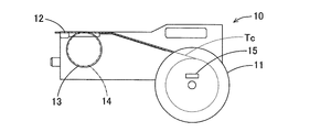
- the component mounting machine M is a general mounting machine, and the carrier tape Tc wound around the reel 11 mounted on the tape feeder 10 (corresponding to the “component supply device” of the present invention) shown in FIG. 4 is used.
- the component e is sent to the component collection position 12, the component e is collected from the carrier tape Tc by the component transfer device, and the collected component e is transferred and mounted on the conveyed substrate.
- Such a component mounting machine M is constructed as a mounting line by arranging a plurality of components, and the mounting control device mc that controls the component mounting of each component mounting machine M exchanges information such as component mounting with the host computer HC. .
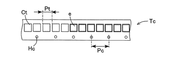
- the carrier tape Tc is formed to be elongated with a predetermined width, and a plurality of cavities Ct are formed with a predetermined pitch Pt in the longitudinal direction.
- cavities Ct components e mounted on the circuit board are respectively stored.
- the upper part of the cavity Ct is opened and covered with a top tape Tt that is attached to the surface of the carrier tape Tc.
- feed holes Hc are formed at a constant pitch Pc in the longitudinal direction.
- a carrier tape Tc in which a plurality of empty cavities Ct in which the component e is not stored on the front end side is continuous is used.
- the carrier tape Tc has the same pitch Pc and size of the feed holes Hc, although the pitch Pt and size of the cavity Ct vary depending on the size of the component e.
- the carrier tape Tc is wound around the reel 11 as shown in FIG.
- the reel 11 is detachably attached to the tape feeder 10.
- the reel 11 is provided with an identifier 15 such as a barcode on which tape identification information such as the type of the component e stored in the carrier tape Tc is recorded.
- the tape feeder 10 has a built-in tape feed mechanism 13 that feeds the carrier tape Tc wound around the reel 11 one by one and supplies the components e one by one to the component collecting position 12 provided at the tip of the tape feeder 10. Is done.
- the tape feed mechanism 13 includes a sprocket 14 that is rotatably supported by the main body of the tape feeder 10 and engages with a feed hole Hc of the carrier tape Tc, and a motor (not shown) that rotates the sprocket 14.
- the reading device 30 is, for example, a bar code reader that optically reads the tape identification information of the identifier 15 attached to the reel 11 and transmits it to the communication device 40 by wire.
- the communication device 40 is, for example, a bridge type device that is connected to the reading device 30 in a wired manner and wirelessly communicates with a host computer HC that manages a mounting control device mc of a plurality of component mounting machines M.
- the display device 90 is, for example, a panel controller that displays various kinds of information such as tape identification information of the identifier 15 and information related to mounting of the component e in the component mounter M.
- the control device 100 is a device that controls the reading device 30, the communication device 40, the display device 90, and the tape connection mechanism W, and includes a communication control unit 101, a display control unit 102, and a connection execution unit 103 (“connection control device of the present invention”). For example).
- the communication control unit 101 controls transmission / reception of data with the reading device 30 and the host computer HC performed via the communication device 40.
- the display control unit 102 receives the tape identification information of the identifier 15 received from the reading device 30 via the communication device 40 and the data sent from the communication control unit 101, and received from the host computer HC via the communication device 40.
- Information such as component mounting in the component mounting machine M is rearranged in the order of high priority, for example, in order of early component out of order, and displayed on the display device 90.
- the connection execution unit 103 is the data sent from the communication control unit 101, and the collation result of the identification information of the carrier tape Tc out of parts received from the host computer HC via the communication device 40 and the new carrier tape Tc. To control the drive of the tape connection mechanism W. In addition, the connection execution unit 103 detects the number of empty cavities Ct that exist at the connection position of the carrier tape Tc that is out of components and the new carrier tape Tc, and sends the detected number to the communication control unit 101. The communication control unit 101 transmits the number of empty cavities Ct detected by the connection execution unit 103 to the host computer HC via the communication device 40.
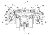
- the configuration of the tape connection mechanism W of the automatic splicing device 20 will be described.
- the first and second tape feeding devices 50 and 51, the first and second origin position detecting devices 63a and 63b, First and second light quantity detection devices 52 and 53, first and second cutting devices 54 and 55, first and second capturing devices 56 and 57, a joining device 58, and a control device 100 (see FIG. 1) ) Etc. are arranged.
- the first and second tape feeders 50 and 51 are arranged on both sides in the casing 21 and the lid 22 (see FIG. 1), respectively.
- the first and second origin position detecting devices 63a and 63b are respectively disposed below first and second sprockets 61a and 61b, which will be described later, of the first and second tape feeding devices 50 and 51, respectively.
- the two light quantity detection devices 52 and 53 are vertically opposed to each other with first and second detection positions Ld1 and Ld2 of first and second transport paths 60a and 60b (described later) of the first and second tape feeding devices 50 and 51, respectively. To be arranged respectively.
- the first and second cutting devices 54 and 55 are disposed at the first and second cutting positions Lf1 and Lf2 between the first and second tape feeding devices 50 and 51, respectively.
- the devices 56 and 57 are disposed between the first and second cutting positions Lf1 and Lf2 between the first and second cutting devices 54 and 55 and the splicing position LS, respectively. 2 between the take-in devices 56, 57.
- the first and second tape feeders 50 and 51 are provided with first and second transport paths 60a and 60b provided to extend in the horizontal direction from both side surfaces of the housing 21 toward the center, and the first and second transports.
- First and second sprockets 61a and 61b disposed below the paths 60a and 60b, first and second gear motors 62a and 62b connected to the first and second sprockets 61a and 61b, and first and second First and second tape detectors 64a, 64b and the like disposed above the transport paths 60a, 60b.
- the first and second cutting devices 54 and 55 move the first and second cutters 68a and 68b provided at the first and second cutting positions Lf1 and Lf2 and the first and second cutters 68a and 68b up and down. And a substantially vertical movement mechanism.
- the 1st, 2nd cutting devices 54 and 55 are constituted so that an unnecessary part can be cut in a cutting part of carrier tape Tc.
- the first and second take-in devices 56 and 57 include first and second take-in members 75a and 75b provided between the first and second cutting positions Lf1 and Lf2 and the splicing position LS. 2 and a drive mechanism (not shown) for driving the intake members 75a and 75b.
- the first and second take-in devices 56 and 57 are configured so as to be able to take in the unnecessary portions of the carrier tape Tc that have been cut.
- the joining device 58 is provided between the first cutting device 54 and the second cutting device 55, and a transport path 60 that forms part of the first and second transport paths 60a and 60b is formed.
- the joining device 58 is configured to be able to connect a carrier tape Tc that is transported along the transport path 60 and that has a cut portion abutted at the center splicing position LS of the transport path 60.
- two carrier tapes Tc to be spliced are fed at a predetermined pitch by the first and second tape feeding devices 50 and 51 from the left and right of FIG. That is, the presence / absence of the carrier tape Tc, the pitch Pt between the adjacent cavities Ct (hereinafter referred to as the pitch Pt of the cavities Ct), the presence / absence of the component e in the cavity Ct (referred to as the component storage cavity Ct and the empty cavity Ct), and the like are detected. .
- a predetermined number of empty cavities Ct are left among a plurality of empty cavities Ct connected to the front end side, and the front end portions are first and second cutters 68a and 68b of the first and second cutting devices 54 and 55, respectively.
- the cut and cut end portions are taken into the first and second take-in members 75a and 75b of the first and second take-in devices 56 and 57, respectively.
- a protective tape with a splicing tape (not shown) connecting the two carrier tapes Tc is fed from a direction orthogonal to the feeding direction of the carrier tapes Tc, and the cut ends of the two carrier tapes Tc are joined to each other by a joining device. At 58, they are connected to each other by splicing tape.
- the control device 100 causes the display device 90 to display the mounter recognition information of the component mounter M and the component identification information indicating that the component has run out received from the host computer HC (steps S1 and S2 in FIG. 5).
- the communication control unit 101 sends the mounter recognition information such as the name of the component mounter M received from the host computer HC and the component identification information such as the name and model number of the component e to the display control unit 102.
- the display control unit 102 displays the mounter recognition information and the component identification information on the display device 90.
- the display control unit 102 displays the mounter recognition information and the component identification information on the display device 90.
- the display device 90 displays the mounter recognition information and the component identification information on the display device 90.
- they are rearranged and displayed on the display device 90 in descending order of priority, for example, in order of the parts being out of order.
- the operator When the operator confirms the mounting machine recognition information and the component identification information that the component is cut by looking at the display device 90, the operator applies the automatic splicing device 20 together with the reel 11 around which the carrier tape Tc containing the corresponding component e is wound. It is transported to the component mounting machine M to be carried by a cart. Then, the operator removes the reel 11 from the tape feeder 10 loaded with the reel 11 that is out of parts. Then, the operator causes the reading device 30 to read the tape identification information such as the name and model number of the part e of each identifier of the reel 11 removed from the tape feeder 10 and the conveyed reel 11.
- the control device 100 displays the tape identification information of each reel 11 read by the reading device 30 on the display device 90 (step S3 in FIG. 5), and transmits the tape identification information to the host computer HC (step in FIG. 5). S4).
- the communication control unit 101 sends the tape identification information of each reel 11 received from the reading device 30 to the display control unit 102 and transmits it to the host computer HC via the communication device 40.
- the display control unit 102 displays the tape identification information of each reel 11 on the display device 90.
- the host computer HC collates the tape identification information with each other and transmits the collation result to the communication control unit 101 via the communication device 40.
- the control device 100 displays the verification result of the tape identification information received from the host computer HC on the display device 90 (steps S5 and S6 in FIG. 5). Specifically, the communication control unit 101 sends the tape identification information collation result received from the host computer HC to the display control unit 102. Then, the display control unit 102 displays the collation result on the display device 90.
- the operator When the operator confirms that the matching is confirmed by looking at the display device 90, the operator automatically splics the rear end portion of the carrier tape Tc of the reel 11 removed from the tape feeder 10 and the front end portion of the carrier tape Tc of the conveyed reel 11. It inserts from the both sides of the housing 21 of the apparatus 20, respectively.
- the control device 100 determines whether or not the collation result is collation coincidence (step S7 in FIG. 5), and if it is judged that the collation result is collation coincidence, the drive of the tape connecting mechanism W is controlled to be inserted.
- the two carrier tapes Tc thus connected are connected (step S8 in FIG. 5), and the tape connection information is transmitted to the host computer HC (step S9 in FIG. 5).
- the communication control unit 101 sends the tape identification information collation result received from the host computer HC to the connection execution unit 103.
- the connection execution unit 103 determines that the collation result is collation coincidence, the drive of the tape connection mechanism W is controlled to connect the two carrier tapes Tc inserted, and the empty cavity Ct existing at the connection position is connected. Is detected and sent to the communication control unit 101.
- the communication control unit 101 transmits the number of empty cavities Ct to the host computer HC via the communication device 40.
- the operator When the connection of the carrier tape Tc is completed, the operator removes the connected carrier tape Tc from the automatic splicing device 20 and loads the reel 11 into the tape feeder 10.
- the host computer HC When the host computer HC receives the number of empty cavities Ct from the communication device 40, the host computer HC transmits the number of empty cavities Ct to the mounting control device mc of the corresponding component mounting machine M.
- the mounting control device mc of the component mounting machine M When the connection position of the carrier tape Tc delivered from the tape feeder 10 reaches the component collection position, the mounting control device mc of the component mounting machine M has the number of empty cavities Ct received from the host computer HC as many as the number of empty cavities Ct. Control to increase the tape feed speed.
- the empty cavity Ct passes through the component collection position, the tape feeder speed of the tape feeder 10 is returned to the original tape feed speed, and the component mounting is continued.
- step S7 determines in step S7 that the collation result does not match
- the tape connection mechanism W is not driven (step S10 in FIG. 5), and a connection suspension warning is displayed on the display device 90.
- Step S11 in FIG. 5 the process returns to Step S3 and the above-described processing is repeated.
- the connection execution unit 103 determines that the collation result does not match
- the connection execution unit 103 does not drive the tape connection mechanism W and sends a connection stop warning to the display control unit 102.
- the display control unit 102 displays a connection cancellation warning on the display device 90.
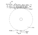
- a plurality of first and second teeth 67a and 67b having the same pitch as the pitch Pc of the feed holes Hc of the carrier tape Tc are formed on the peripheral edges of the first and second sprockets 61a and 61b.
- the first and second teeth 67a and 67b are formed at intervals equal to or greater than the feed pitch of the carrier tape Tc.
- the first and second sprockets 61a and 61b include first and second teeth 67au and 67bu that have rotated to the top of the rotating first and second teeth 67a and 67b, and first and second transport paths. It arrange
- the first and second tape detectors 64a and 64b detect that the carrier tape Tc has been inserted.
- the first and second origin position detection devices 63a and 63b detect one first and second teeth 67a and 67b among the plurality of first and second teeth 67a and 67b of the first and second sprockets 61a and 61b. To do.
- the positions of the plurality of first and second teeth 67a and 67b of the first and second sprockets 61a and 61b are defined as the origin positions of the first and second tape feeders 50 and 51, respectively. Therefore, the first and second origin position detection devices 63a and 63b are sensors that detect the plurality of origin positions of the first and second tape feeding devices 50 and 51, respectively.
- the first and second origin position detecting devices 63a and 63b are the first and second teeth 67ad and 67bd (origin positions) that have rotated to the lowermost of the rotating first and second teeth 67a and 67b. Is detected, the first and second teeth 67au and 67bu have rotated to the top of the rotating first and second teeth 67a and 67b, and the first and second transport paths 60a and 60b. It arrange
- the first and second light quantity detection devices 52 and 53 detect the transmitted light quantity of the cavity Ct and the like of the carrier tape Tc sent by the first and second sprockets 61a and 61b.
- the light amounts detected by the first and second light amount detection devices 52 and 53 show the maximum value Lmax when not shielded by the carrier tape Tc, that is, in the saturated state, and are smaller than the predetermined value La in the empty cavity Ct. Become.
- the value Lb smaller than the predetermined value La is set as a threshold value and the detected light quantity is smaller than the threshold value Lb ( ⁇ La)
- the detection positions (positions of the sensor optical axis S) of the first and second light quantity detection devices 52 and 53 are the positions of the first and second sprockets 61a and 61b in the first and second origin position detection devices 63a and 63b.
- the transmitted light quantity of the cavity Ctb is detected so that the cavity Ctb formed at the same position as the feed hole Hcb of the carrier tape Tc is located. Placed in.
- the position of the feed hole Hcb at the same position as the cavity Ctb detected by the first and second light quantity detection devices 52 and 53 is defined as the tape reference position (position of the feed hole Hcb) of the carrier tape Tc. Therefore, the origin positions of the first and second tape feeders 50 and 51 (the positions of the first and second teeth 67ad and 67bd) are in a fixed positional relationship with the tape reference position (the position of the feed hole Hcb) of the carrier tape Tc. Will have.
- the tape reference position determination operation based on the first position and the first origin position will be described with reference to FIGS. Since the operation for determining the tape reference position for the carrier tape Tc inserted from both sides of the automatic splicing device 20 is the same, the operation for determining the tape reference position for the carrier tape Tc inserted from the right side of FIG. Will be explained.
- the tape tip Th of the carrier tape Tc is between the cavity Ct of the feed hole Hc indicated by the phantom line (dashed line) and the cavity Ct adjacent to the cavity Ct. The tape part.
- FIG. 7 shows a detection state of the first origin position immediately before the leading edge of the carrier tape Tc is detected.
- the first origin position detector 63a detects the lowermost first tooth 67ad1 of the first sprocket 61a, that is, the uppermost first tooth 67au1 of the first sprocket 61a and the feed hole Hcd1 of the carrier tape Tc.
- the position of the tape tip Th of the carrier tape Tc when the two are engaged with each other is the upstream side of conveyance by a quarter pitch (Pc / 4) from the detection position of the first light quantity detection device 52 (position of the sensor optical axis S). Are separated.
- the first tooth 67a detected next to the first tooth 67ad1 is denoted by reference numeral 67ad1
- the first tooth 67a that meshes with the feed hole Hcd2 next to the first tooth 67au1 is denoted by reference numeral 67au1.
- FIG. 8 shows the state of detecting the tip of the carrier tape Tc. That is, the first sprocket 61a rotates by the distance Pc / 4 from the first origin position detection (detection of the first teeth 67ad1) state in FIG. 7, and the carrier tape Tc advances by the distance Pc / 4, and the tape tip Th Shows a state where the detection position of the first light quantity detection device 52 (the position of the sensor optical axis S) has been reached. The position of the first tooth 67ad1 at this time is defined as a first position.
- the reference position is determined by detecting the first origin position, that is, the position where the first tooth 67ad1 is detected by the first origin position detection device 63a, and the first position, ie, the first tooth 67ad1, detected by the first origin position detection device 63a. Then, the feed amount of the carrier tape Tc from the first origin position to the first position, that is, the distance Pc / 4 is obtained from the position rotated by the distance Pc / 4. Then, the difference between the adjacent origin positions, that is, the distance Pc, and the feed amount of the carrier tape Tc from the first origin position to the first position, that is, the distance Pc / 4, that is, the distance 3Pc / 4 is obtained.
- the carrier tape Tc is sent from the state of FIG. 9 by the calculated distance 3Pc / 4, it is the same as the cavity Ct of the carrier tape Tc located at the detection position of the first light quantity detection device 52 (position of the sensor optical axis S).
- the position of the position feed hole Hc is determined as a tape reference position having a certain relationship with the first origin position.
- FIG. 9 shows a state where the carrier tape Tc is located at the tape reference position.
- the first origin position detection device 63a detects the lowermost first tooth 67ad2 that rotates next to the first tooth 67au1 of the first sprocket 61a, and follows the first tooth 67au1 of the first sprocket 61a.
- the uppermost first tooth 67au2 rotating in the direction of the carrier tape Tc and the feed hole Hcd2 fed next to the feed hole Hcd1 of the carrier tape Tc are meshed with each other, and the origin position detection state immediately after detecting the leading end of the carrier tape Tc Indicates.
- the tape reference position is the position of the feed hole Hcd0 formed at the same position as the cavity Ctb located at the detection position (position of the sensor optical axis S) of the first light quantity detection device 52.
- the empty cavity Ct of the carrier tape Tc is detected based on a predetermined light intensity threshold value for discriminating the preset empty cavity Ct, the tape portion (a portion between adjacent cavities Ct) and the component storage cavity Ct, Based on the detection period, the pitch Pc of the cavity Ct is calculated.
- the first detected cavity Ct is determined as the component storage cavity Ct. As described above, the number of empty cavities can be detected.
- the automatic splicing device 20 is configured to be able to communicate with the host computer HC via the communication device 40. However, the automatic splicing device 20 may be configured to be able to communicate with a plurality of component mounting machines M individually. . In the above-described embodiment, the automatic splicing device 20 is configured to communicate with the reading device 30 via the communication device 40 via a wire. However, the reading device 30 is configured to be portable and the communication device 40 is configured to be portable. It is good also as a structure which communicates by radio
- the automatic splicing device 20 of the present invention has a first tape (carrier tape) Tc provided with a feed hole Hc and a component storage cavity Ct at a constant interval Pc, and a feed hole Hc and a component storage at a constant interval Pc.
- An automatic splicing device 20 having a tape connecting mechanism W for automatically connecting a second tape (carrier tape) Tc provided with a cavity Ct by a splicing tape at a splicing position, and a first reel around which the first tape Tc is wound 11 and the second tape 11 on which the second tape Tc is wound, respectively, and reads the identification information in which the information of the component e stored in each cavity Ct of the first tape Tc and the second tape Tc is recorded.
- a host computer connected to be communicable with the device 30 and the reading device 30 and the component mounter M or the component mounter M Includes a communication apparatus 40 for communicating with HC, the control device 100 for controlling the tape attachment W and the communication device 40, the.
- the automatic splicing device 20 connects the carrier tape Tc wound around the reel 11 and the new carrier tape Tc based on the information on the reel 11 and the like transmitted from the component mounting machine M and the like. It is possible to prevent misrecognition of the reel 11 around which the power carrier tape Tc is wound. Therefore, in the component mounting machine M, it is possible to prevent a decrease in production efficiency due to the misrecognition of the reel 11.
- control device 100 communicates the identification information of the first tape Tc and the second tape Tc read by the reading device 30 and the component mounting machine M or the host computer HC connected so as to be communicable with the component mounting machine M.
- the drive of the tape connection mechanism W is controlled according to the collation result with the identification information of the first tape Tc and the second tape Tc received via the tape. Thereby, connection of the carrier tape Tc which accommodated the different kinds of components e can be prevented beforehand.
- the communication device 40 performs wireless communication with the component mounting machine M or the host computer HC that is communicably connected to the component mounting machine M.
- the automatic splicing device 20 is located at a location away from the component mounter M where the component breakage has occurred, the operator can check the component mounter M and cope with it.
- the reading device 30 is portable and performs wireless communication with the communication device 40. Thereby, even if the worker is in a place away from the automatic splicing device 20, it is possible to confirm and respond to the part cut.
Landscapes
- Engineering & Computer Science (AREA)
- Manufacturing & Machinery (AREA)
- Microelectronics & Electronic Packaging (AREA)
- Operations Research (AREA)
- Supply And Installment Of Electrical Components (AREA)
Abstract
Description
本実施形態の自動スプライシング装置の概略構成について図を参照して説明する。図1に示すように、自動スプライシング装置20は、詳細は後述するが、読取装置30と、通信装置40と、表示装置90と、制御装置100等とを備え、図2に示す第1、第2テープ送り装置50,51等のテープ接続機構Wを有する装置である。
通信装置40は、読取装置30と有線で接続され、また複数台の部品実装機Mの実装制御装置mcを管理するホストコンピュータHCと無線で通信する例えばブリッジタイプの装置である。
制御装置100は、読取装置30、通信装置40、表示装置90及びテープ接続機構Wを制御する装置であり、通信制御部101、表示制御部102及び接続実行部103(本発明の「接続制御装置」に相当)等を備える。
表示制御部102は、通信制御部101から送られてくるデータである、読取装置30から通信装置40を介して受信した識別子15のテープ識別情報、ホストコンピュータHCから通信装置40を介して受信した部品実装機Mにおける部品実装等の情報を優先度の高い順、例えば部品切れとなるのが早い順に並べ替えて表示装置90に表示する。
次に、自動スプライシング装置20のテープ接続機構Wの構成について説明する。
図2に示すように、自動スプライシング装置20の筺体21(図1参照)内には、第1、第2テープ送り装置50,51と、第1、第2原点位置検出装置63a,63bと、第1、第2光量検出装置52,53と、第1、第2切断装置54,55と、第1、第2取込装置56,57と、接合装置58と、制御装置100(図1参照)等とが配置される。
次に、自動スプライシング装置20の制御装置100の動作について図5のフローチャートを参照して説明する。
ホストコンピュータHCは、各部品実装機Mの実装制御装置mcから送信される部品実装等の情報により、部品切れとなるリール11を有する部品実装機Mを特定したら、当該部品実装機Mの実装機認識情報及び部品切れとなる部品識別情報を自動スプライシング装置20の制御装置100に送信する。
次に、自動スプライシング装置20における空キャビティの検出について図6を参照して説明する。
第1、第2スプロケット61a,61bの周縁には、キャリアテープTcの送り穴HcのピッチPcと同一ピッチの複数の第1、第2歯67a,67bが形成される。本実施形態では、第1、第2歯67a,67bは、キャリアテープTcの送りピッチ以上の間隔で形成される。第1、第2スプロケット61a,61bは、回転している第1、第2歯67a,67bのうち最上部に回転してきた第1、第2歯67au,67buと、第1、第2搬送経路60a,60bに沿って挿入されてくるキャリアテープTcの送り穴Hcdとが噛合可能なように、第1、第2搬送経路60a,60bの下方に配置される。
本発明の自動スプライシング装置20は、一定の間隔Pcに送り穴Hcと部品収納用のキャビティCtを設けた第1テープ(キャリアテープ)Tcに、一定の間隔Pcに送り穴Hcと部品収納用のキャビティCtを設けた第2テープ(キャリアテープ)Tcをスプライシング位置でスプライシングテープによって自動的に接続するテープ接続機構Wを有する自動スプライシング装置20であって、第1テープTcを巻回した第1リール11及び第2テープTcを巻回した第2リール11にそれぞれ付され、第1テープTc及び第2テープTcの各キャビティCtに収納された部品eの情報がそれぞれ記録された識別情報を読取る読取装置30と、読取装置30及び部品実装機Mあるいは部品実装機Mと通信可能に接続されたホストコンピュータHCと通信する通信装置40と、テープ接続機構W及び通信装置40を制御する制御装置100と、を備える。
また、読取装置30は、携帯可能で通信装置40と無線通信を行なう。これにより、作業者は、自動スプライシング装置20から離れた場所にいても、部品切れを確認して対応することができる。
Claims (4)
- 一定の間隔に送り穴と部品収納用のキャビティを設けた第1テープに、一定の間隔に送り穴と部品収納用のキャビティを設けた第2テープをスプライシング位置でスプライシングテープによって自動的に接続するテープ接続機構を有する自動スプライシング装置であって、
前記第1テープを巻回した第1リール及び前記第2テープを巻回した第2リールにそれぞれ付され、前記第1テープ及び前記第2テープの各キャビティに収納された部品の情報がそれぞれ記録された識別情報を読取る読取装置と、
前記読取装置及び部品実装機あるいは部品実装機と通信可能に接続されたホストコンピュータと通信する通信装置と、
前記テープ接続機構及び前記通信装置を制御する制御装置と、
を備える、自動スプライシング装置。 - 前記制御装置は、
前記読取装置で読取った前記第1テープ及び前記第2テープの前記識別情報と、
前記部品実装機あるいは前記部品実装機と通信可能に接続されたホストコンピュータから前記通信装置を介して受信した前記第1テープ及び前記第2テープの前記識別情報との照合結果によって、前記テープ接続機構の駆動を制御する、請求項1に記載の自動スプライシング装置。 - 前記通信装置は、前記部品実装機あるいは前記部品実装機と通信可能に接続されたホストコンピュータと無線通信を行なう、請求項1又は2に記載の自動スプライシング装置。
- 前記読取装置は、携帯可能で前記通信装置と無線通信を行なう、請求項1から3の何れか一項に記載の自動スプライシング装置。
Priority Applications (5)
| Application Number | Priority Date | Filing Date | Title |
|---|---|---|---|
| CN201580077759.2A CN107409487B (zh) | 2015-03-31 | 2015-03-31 | 自动拼接装置 |
| EP15887591.4A EP3280239B1 (en) | 2015-03-31 | 2015-03-31 | Automatic splicing device |
| JP2017508946A JP6577022B2 (ja) | 2015-03-31 | 2015-03-31 | 自動スプライシング装置 |
| US15/562,107 US20180072525A1 (en) | 2015-03-31 | 2015-03-31 | Automatic splicing device |
| PCT/JP2015/060216 WO2016157438A1 (ja) | 2015-03-31 | 2015-03-31 | 自動スプライシング装置 |
Applications Claiming Priority (1)
| Application Number | Priority Date | Filing Date | Title |
|---|---|---|---|
| PCT/JP2015/060216 WO2016157438A1 (ja) | 2015-03-31 | 2015-03-31 | 自動スプライシング装置 |
Publications (1)
| Publication Number | Publication Date |
|---|---|
| WO2016157438A1 true WO2016157438A1 (ja) | 2016-10-06 |
Family
ID=57006641
Family Applications (1)
| Application Number | Title | Priority Date | Filing Date |
|---|---|---|---|
| PCT/JP2015/060216 WO2016157438A1 (ja) | 2015-03-31 | 2015-03-31 | 自動スプライシング装置 |
Country Status (5)
| Country | Link |
|---|---|
| US (1) | US20180072525A1 (ja) |
| EP (1) | EP3280239B1 (ja) |
| JP (1) | JP6577022B2 (ja) |
| CN (1) | CN107409487B (ja) |
| WO (1) | WO2016157438A1 (ja) |
Cited By (1)
| Publication number | Priority date | Publication date | Assignee | Title |
|---|---|---|---|---|
| US10457512B2 (en) | 2016-09-19 | 2019-10-29 | New Era Converting Machinery, Inc. | Automatic lapless butt material splice |
Families Citing this family (1)
| Publication number | Priority date | Publication date | Assignee | Title |
|---|---|---|---|---|
| CN111268484B (zh) * | 2020-03-23 | 2021-08-03 | 惠州市集广新材料科技有限公司 | 载带连接装置 |
Citations (4)
| Publication number | Priority date | Publication date | Assignee | Title |
|---|---|---|---|---|
| JPH06179412A (ja) * | 1992-12-10 | 1994-06-28 | Matsushita Electric Ind Co Ltd | テーピング電子部品の接続装置 |
| JP2004031875A (ja) * | 2002-06-28 | 2004-01-29 | Matsushita Electric Ind Co Ltd | 電子部品供給装置、電子部品実装装置、電子部品供給方法、及び部品実装方法 |
| JP2012104635A (ja) * | 2010-11-10 | 2012-05-31 | Fuji Mach Mfg Co Ltd | スプライシング誤作業防止方法 |
| WO2014167692A1 (ja) * | 2013-04-11 | 2014-10-16 | 富士機械製造株式会社 | スプライシング装置 |
Family Cites Families (9)
| Publication number | Priority date | Publication date | Assignee | Title |
|---|---|---|---|---|
| JPH06302992A (ja) * | 1993-04-14 | 1994-10-28 | Toshiba Corp | 部品実装機のカートリッジ構造及び部品実装機の管理システム |
| US6817216B2 (en) * | 2002-08-22 | 2004-11-16 | Accu-Assembly Incorporated | Electronic component placement |
| US20080078829A1 (en) * | 2006-09-29 | 2008-04-03 | Siemens Energy & Automation, Inc | Inventory manager service and assistant for PCB manufacturing |
| JP5357743B2 (ja) * | 2009-12-26 | 2013-12-04 | 富士機械製造株式会社 | 電子回路部品供給装置 |
| JP5223881B2 (ja) * | 2010-04-19 | 2013-06-26 | パナソニック株式会社 | 部品実装装置における部品供給方法 |
| US8430379B2 (en) * | 2010-10-27 | 2013-04-30 | Ido Goldstein | Apparatus for dispensing fog |
| CN104221488B (zh) * | 2012-04-18 | 2017-03-01 | 富士机械制造株式会社 | 拼接装置及连接方法 |
| CN104221486B (zh) * | 2012-04-18 | 2016-12-07 | 富士机械制造株式会社 | 自动拼接装置 |
| CN104221487B (zh) * | 2012-04-18 | 2017-03-01 | 富士机械制造株式会社 | 自动拼接装置 |
-
2015
- 2015-03-31 EP EP15887591.4A patent/EP3280239B1/en active Active
- 2015-03-31 JP JP2017508946A patent/JP6577022B2/ja active Active
- 2015-03-31 WO PCT/JP2015/060216 patent/WO2016157438A1/ja active Application Filing
- 2015-03-31 CN CN201580077759.2A patent/CN107409487B/zh active Active
- 2015-03-31 US US15/562,107 patent/US20180072525A1/en not_active Abandoned
Patent Citations (4)
| Publication number | Priority date | Publication date | Assignee | Title |
|---|---|---|---|---|
| JPH06179412A (ja) * | 1992-12-10 | 1994-06-28 | Matsushita Electric Ind Co Ltd | テーピング電子部品の接続装置 |
| JP2004031875A (ja) * | 2002-06-28 | 2004-01-29 | Matsushita Electric Ind Co Ltd | 電子部品供給装置、電子部品実装装置、電子部品供給方法、及び部品実装方法 |
| JP2012104635A (ja) * | 2010-11-10 | 2012-05-31 | Fuji Mach Mfg Co Ltd | スプライシング誤作業防止方法 |
| WO2014167692A1 (ja) * | 2013-04-11 | 2014-10-16 | 富士機械製造株式会社 | スプライシング装置 |
Cited By (3)
| Publication number | Priority date | Publication date | Assignee | Title |
|---|---|---|---|---|
| US10457512B2 (en) | 2016-09-19 | 2019-10-29 | New Era Converting Machinery, Inc. | Automatic lapless butt material splice |
| US10899568B2 (en) | 2016-09-19 | 2021-01-26 | New Era Converting Machinery, Inc. | Automatic lapless butt material splice |
| US11767189B2 (en) | 2016-09-19 | 2023-09-26 | New Era Converting Machinery, Inc. | Automatic lapless butt material splice |
Also Published As
| Publication number | Publication date |
|---|---|
| CN107409487B (zh) | 2020-07-28 |
| JP6577022B2 (ja) | 2019-09-18 |
| EP3280239B1 (en) | 2020-12-23 |
| EP3280239A1 (en) | 2018-02-07 |
| EP3280239A4 (en) | 2018-04-11 |
| JPWO2016157438A1 (ja) | 2018-01-25 |
| US20180072525A1 (en) | 2018-03-15 |
| CN107409487A (zh) | 2017-11-28 |
Similar Documents
| Publication | Publication Date | Title |
|---|---|---|
| JP6603705B2 (ja) | 自動スプライシング装置 | |
| CN111919522B (zh) | 作业管理系统及元件安装系统 | |
| JP6449989B2 (ja) | 自動スプライシング装置及び部品実装機 | |
| JP6577022B2 (ja) | 自動スプライシング装置 | |
| JP6420364B2 (ja) | テープの自動検知装置及び自動検知方法 | |
| JP6862513B2 (ja) | 自動スプライシング方法 | |
| JP6902608B2 (ja) | テープ装着管理装置及び部品実装システム | |
| JP6714720B2 (ja) | 部品照合システム | |
| CN109906673B (zh) | 料带误安装检测系统 | |
| JP4728163B2 (ja) | 部品供給装置 | |
| JP6835699B2 (ja) | テープ装着管理装置及びそれを備えた部品実装システム | |
| JP6078557B2 (ja) | 部品供給ユニット | |
| JP2017220623A (ja) | テープの自動検知装置 | |
| US11622487B2 (en) | Component shortage detection device | |
| JPWO2019087291A1 (ja) | 部品供給装置及びテープフィーダー |
Legal Events
| Date | Code | Title | Description |
|---|---|---|---|
| 121 | Ep: the epo has been informed by wipo that ep was designated in this application |
Ref document number: 15887591 Country of ref document: EP Kind code of ref document: A1 |
|
| ENP | Entry into the national phase |
Ref document number: 2017508946 Country of ref document: JP Kind code of ref document: A |
|
| REEP | Request for entry into the european phase |
Ref document number: 2015887591 Country of ref document: EP |
|
| WWE | Wipo information: entry into national phase |
Ref document number: 15562107 Country of ref document: US |
|
| NENP | Non-entry into the national phase |
Ref country code: DE |