WO2016152866A1 - 固定装置、蒸気タービン、回転機械の製造方法及び組立方法 - Google Patents
固定装置、蒸気タービン、回転機械の製造方法及び組立方法 Download PDFInfo
- Publication number
- WO2016152866A1 WO2016152866A1 PCT/JP2016/059019 JP2016059019W WO2016152866A1 WO 2016152866 A1 WO2016152866 A1 WO 2016152866A1 JP 2016059019 W JP2016059019 W JP 2016059019W WO 2016152866 A1 WO2016152866 A1 WO 2016152866A1
- Authority
- WO
- WIPO (PCT)
- Prior art keywords
- hole
- rotating machine
- pin
- radial direction
- radially
- Prior art date
- Legal status (The legal status is an assumption and is not a legal conclusion. Google has not performed a legal analysis and makes no representation as to the accuracy of the status listed.)
- Ceased
Links
Images








Classifications
-
- F—MECHANICAL ENGINEERING; LIGHTING; HEATING; WEAPONS; BLASTING
- F01—MACHINES OR ENGINES IN GENERAL; ENGINE PLANTS IN GENERAL; STEAM ENGINES
- F01D—NON-POSITIVE DISPLACEMENT MACHINES OR ENGINES, e.g. STEAM TURBINES
- F01D25/00—Component parts, details, or accessories, not provided for in, or of interest apart from, other groups
- F01D25/24—Casings; Casing parts, e.g. diaphragms, casing fastenings
- F01D25/26—Double casings; Measures against temperature strain in casings
- F01D25/265—Vertically split casings; Clamping arrangements therefor
-
- F—MECHANICAL ENGINEERING; LIGHTING; HEATING; WEAPONS; BLASTING
- F16—ENGINEERING ELEMENTS AND UNITS; GENERAL MEASURES FOR PRODUCING AND MAINTAINING EFFECTIVE FUNCTIONING OF MACHINES OR INSTALLATIONS; THERMAL INSULATION IN GENERAL
- F16B—DEVICES FOR FASTENING OR SECURING CONSTRUCTIONAL ELEMENTS OR MACHINE PARTS TOGETHER, e.g. NAILS, BOLTS, CIRCLIPS, CLAMPS, CLIPS OR WEDGES; JOINTS OR JOINTING
- F16B13/00—Dowels or other devices fastened in walls or the like by inserting them in holes made therein for that purpose
- F16B13/04—Dowels or other devices fastened in walls or the like by inserting them in holes made therein for that purpose with parts gripping in the hole or behind the reverse side of the wall after inserting from the front
- F16B13/08—Dowels or other devices fastened in walls or the like by inserting them in holes made therein for that purpose with parts gripping in the hole or behind the reverse side of the wall after inserting from the front with separate or non-separate gripping parts moved into their final position in relation to the body of the device without further manual operation
- F16B13/0858—Dowels or other devices fastened in walls or the like by inserting them in holes made therein for that purpose with parts gripping in the hole or behind the reverse side of the wall after inserting from the front with separate or non-separate gripping parts moved into their final position in relation to the body of the device without further manual operation with an expansible sleeve or dowel body driven against a tapered or spherical expander plug
-
- F—MECHANICAL ENGINEERING; LIGHTING; HEATING; WEAPONS; BLASTING
- F16—ENGINEERING ELEMENTS AND UNITS; GENERAL MEASURES FOR PRODUCING AND MAINTAINING EFFECTIVE FUNCTIONING OF MACHINES OR INSTALLATIONS; THERMAL INSULATION IN GENERAL
- F16B—DEVICES FOR FASTENING OR SECURING CONSTRUCTIONAL ELEMENTS OR MACHINE PARTS TOGETHER, e.g. NAILS, BOLTS, CIRCLIPS, CLAMPS, CLIPS OR WEDGES; JOINTS OR JOINTING
- F16B19/00—Bolts without screw-thread; Pins, including deformable elements; Rivets
- F16B19/02—Bolts or sleeves for positioning of machine parts, e.g. notched taper pins, fitting pins, sleeves, eccentric positioning rings
-
- F—MECHANICAL ENGINEERING; LIGHTING; HEATING; WEAPONS; BLASTING
- F16—ENGINEERING ELEMENTS AND UNITS; GENERAL MEASURES FOR PRODUCING AND MAINTAINING EFFECTIVE FUNCTIONING OF MACHINES OR INSTALLATIONS; THERMAL INSULATION IN GENERAL
- F16B—DEVICES FOR FASTENING OR SECURING CONSTRUCTIONAL ELEMENTS OR MACHINE PARTS TOGETHER, e.g. NAILS, BOLTS, CIRCLIPS, CLAMPS, CLIPS OR WEDGES; JOINTS OR JOINTING
- F16B33/00—Features common to bolt and nut
- F16B33/004—Sealing; Insulation
-
- F—MECHANICAL ENGINEERING; LIGHTING; HEATING; WEAPONS; BLASTING
- F16—ENGINEERING ELEMENTS AND UNITS; GENERAL MEASURES FOR PRODUCING AND MAINTAINING EFFECTIVE FUNCTIONING OF MACHINES OR INSTALLATIONS; THERMAL INSULATION IN GENERAL
- F16J—PISTONS; CYLINDERS; SEALINGS
- F16J15/00—Sealings
- F16J15/02—Sealings between relatively-stationary surfaces
- F16J15/04—Sealings between relatively-stationary surfaces without packing between the surfaces, e.g. with ground surfaces, with cutting edge
-
- F—MECHANICAL ENGINEERING; LIGHTING; HEATING; WEAPONS; BLASTING
- F05—INDEXING SCHEMES RELATING TO ENGINES OR PUMPS IN VARIOUS SUBCLASSES OF CLASSES F01-F04
- F05D—INDEXING SCHEME FOR ASPECTS RELATING TO NON-POSITIVE-DISPLACEMENT MACHINES OR ENGINES, GAS-TURBINES OR JET-PROPULSION PLANTS
- F05D2220/00—Application
- F05D2220/30—Application in turbines
- F05D2220/31—Application in turbines in steam turbines
-
- F—MECHANICAL ENGINEERING; LIGHTING; HEATING; WEAPONS; BLASTING
- F05—INDEXING SCHEMES RELATING TO ENGINES OR PUMPS IN VARIOUS SUBCLASSES OF CLASSES F01-F04
- F05D—INDEXING SCHEME FOR ASPECTS RELATING TO NON-POSITIVE-DISPLACEMENT MACHINES OR ENGINES, GAS-TURBINES OR JET-PROPULSION PLANTS
- F05D2230/00—Manufacture
- F05D2230/60—Assembly methods
-
- F—MECHANICAL ENGINEERING; LIGHTING; HEATING; WEAPONS; BLASTING
- F05—INDEXING SCHEMES RELATING TO ENGINES OR PUMPS IN VARIOUS SUBCLASSES OF CLASSES F01-F04
- F05D—INDEXING SCHEME FOR ASPECTS RELATING TO NON-POSITIVE-DISPLACEMENT MACHINES OR ENGINES, GAS-TURBINES OR JET-PROPULSION PLANTS
- F05D2240/00—Components
- F05D2240/10—Stators
- F05D2240/14—Casings or housings protecting or supporting assemblies within
-
- F—MECHANICAL ENGINEERING; LIGHTING; HEATING; WEAPONS; BLASTING
- F05—INDEXING SCHEMES RELATING TO ENGINES OR PUMPS IN VARIOUS SUBCLASSES OF CLASSES F01-F04
- F05D—INDEXING SCHEME FOR ASPECTS RELATING TO NON-POSITIVE-DISPLACEMENT MACHINES OR ENGINES, GAS-TURBINES OR JET-PROPULSION PLANTS
- F05D2260/00—Function
- F05D2260/30—Retaining components in desired mutual position
Definitions
- the present invention relates to a fixing device that fixes the relative position in the rotational direction of two members on the stationary side of a rotating machine, a steam turbine having the fixing device, a method of manufacturing the rotating machine, and a method of assembling the rotating machine.
- Rotating machines include steam turbines, gas turbines, and compressors.
- a steam turbine includes an outer casing, an inner casing provided in the outer casing, a rotor inserted into the inner casing, a plurality of rotor blades arranged in multiple stages on the rotor, and an inner casing.
- a plurality of stationary blades arranged in multiple stages. Multistage moving blades and stationary blades are alternately arranged in the axial direction of the rotor.
- steam turbine steam enters the inner casing and is supplied to a space where the multistage stationary blades and moving blades are arranged. Drive the generator.
- the rotating machine determines the relative positions of the stationary side (fixed side) member (stationary body) including the outer casing, the inner casing, and the stationary blade, such as the rotating direction, the axial direction, and the horizontal direction of the rotating machine.
- Various devices are provided for fixing.
- a device for fixing the relative position of a stationary member in the rotation direction of a rotating machine the relative position between a blade ring that supports a stationary blade and an inner casing that supports the blade ring is fixed.
- An apparatus is described.
- the device described in Patent Document 1 has a radial pin (eccentric pin) that is inserted into a hole formed in the inner casing and whose tip is inserted into a recess formed in the blade ring.
- the radial pin is fixed to the inner casing by being fixed to the inner casing using a pin.
- the apparatus of patent document 1 provides the cover body in the radial direction outer side of the rotary machine of a radial pin, and has fixed the cover body to the outer compartment with the volt
- the fixing device disclosed in Patent Document 1 has a lid disposed on the radially outer side of the rotary machine of the radial pin, and the radial pin moves radially outward of the rotary machine by fixing the lid to the vehicle compartment with a bolt.
- a force for moving the lid from the radial pin to the outer side in the radial direction of the rotating machine acts on the lid, so it is necessary to increase the size of the fastening member such as a bolt of the lid.
- the fastening member such as a bolt of the lid.
- the present invention solves the above-described problem, and can fix the radial pin inserted into the outer member and the inner member to the outside in the radial direction of the rotating machine, and has a simple structure, It is an object of the present invention to provide a steam turbine, a method for manufacturing a rotary machine, and a method for assembling the rotary machine.
- the present invention for achieving the above object is a fixing device for fixing a relative position in a circumferential direction of an outer member and an inner member of a stationary body of a rotary machine, wherein the outer member is disposed radially outside the rotary machine.
- An outer hole that opens and an inner hole that communicates with the outer hole and has a smaller diameter than the outer hole and opens radially inward of the rotary machine are formed in the radial direction of the rotary machine of the outer member.
- a surface that is inserted into the outer hole on the outer side in the radial direction of the rotary machine and formed on the outer side in the radial direction of the rotary machine is a surface that is formed on the outer hole and faces the inner side in the radial direction of the rotary machine, and the diameter of the through hole Overlap in direction, and And having a pin supporting unit that overlaps in the radial direction of the radial pin and the through hole.
- the pin support unit may include a support sleeve having a surface formed on a radially outer side of the rotating machine, and a spacer disposed on the inner side of the support sleeve and in contact with an inner peripheral surface of the support sleeve. preferable.
- a support unit insertion groove that is recessed in the radial direction of the outer hole is formed on the inner peripheral surface of the outer hole, and the support unit insertion groove faces the radially inner side of the rotary machine toward the radially outer side of the rotary machine.
- a surface that faces the radially inner side of the rotating machine is in contact with a surface that is formed on the radially outer side of the rotating machine of the supporting sleeve, and the outer circumferential surface of the supporting sleeve is the supporting unit insertion groove. It is preferable to contact with.
- the support sleeve has a plurality of divided sleeves divided in the circumferential direction of the through hole.
- the support sleeve has a cylindrical shape in which a slit is formed, and the spacer has a shape whose diameter decreases from the outer side in the radial direction to the inner side of the rotary machine.
- the slit is formed along the radial direction of the rotary machine from the outer end face or the inner end face of the support sleeve in the radial direction of the rotary machine.
- the pin support unit has a lid member that is arranged on the outer side in the radial direction of the rotating machine and is fixed to the outer member.
- the outer peripheral surface of the support sleeve is perpendicular to a surface of the outer hole facing the radially inner side of the rotary machine.
- a liner disposed between the pin support unit and the radial pin and in contact with the pin support unit.
- the support unit insertion groove is formed with a surface that is in contact with the outer peripheral surface of the support sleeve and perpendicular to the radial direction of the outer hole, and a surface that faces a surface facing the radially inner side of the rotating machine. It is preferable.
- the support unit insertion groove is formed with a surface that is in contact with the outer peripheral surface of the support sleeve and that faces the radially inner side of the outer hole as it goes from the radially outer side to the inner side of the rotating machine.
- a seal unit that is inserted into the through hole and seals the through hole on the radial inside of the rotary machine with respect to the pin support unit.
- the seal unit includes a seal sleeve in which a diameter of an inner peripheral surface changes along a radial direction of the rotary machine, and a columnar insertion member that is inserted into the seal sleeve and is in contact with the inner peripheral surface of the seal sleeve. It is preferable that the outer peripheral surface of the seal sleeve is in contact with the through-hole, and the inner peripheral surface of the seal sleeve is in contact with the insertion member.
- the present invention for achieving the above object is a steam turbine, wherein the fixing device according to any one of the above, the outer member, the inner member, and the radial direction of the rotating machine rather than the inner member. And a rotating body disposed inside.
- the present invention provides a rotating machine manufacturing method for manufacturing a rotating machine by fixing the relative positions in the circumferential direction of the outer member and the inner member of the stationary body of the rotating machine.
- a radial pin having a flange portion whose outer diameter is larger than the diameter of the inner hole is inserted into a through hole penetrating in the radial direction of the rotating machine, and an end portion of the radial pin on the radially inner side of the rotating machine is inserted.
- the pin support unit includes a support sleeve having a surface formed on a radially outer side of the rotating machine, and a spacer inserted inside the support sleeve, and the pin support unit installation step includes: A step of disposing a surface of the support sleeve formed radially outside the rotating machine at a position in contact with a surface of the outer hole facing the radially inner side of the rotating machine; and inserting the spacer inside the support sleeve Preferably comprising steps.
- the pin support unit includes a support sleeve having a surface formed on a radially outer side of the rotating machine, and a spacer inserted inside the support sleeve
- the pin support unit installation step includes: Disposing a support sleeve in the outer hole; inserting the spacer inside the support sleeve; moving the support sleeve radially outward of the through hole; And moving the surface formed on the outer hole to a position in contact with the surface facing the radially inner side of the rotating machine of the outer hole.
- the present invention provides a rotating machine assembly method for manufacturing a rotating machine by fixing the relative positions in the circumferential direction of an outer member and an inner member of a stationary body of the rotating machine.
- a radial pin having a flange portion whose outer diameter is larger than the diameter of the inner hole is inserted into a through hole penetrating in the radial direction of the rotating machine, and an end portion of the radial pin on the radially inner side of the rotating machine is inserted.
- the radial pin inserted into the outer member and the inner member can be prevented from moving radially outward of the rotary machine, and has a simple structure. Can do.
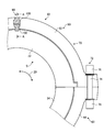
- FIG. 1 is a partial cross-sectional view showing a schematic configuration of a steam turbine having a fixing device according to an embodiment of the present invention.
- FIG. 2 is a sectional view conceptually showing the fixed unit of the steam turbine shown in FIG.
- FIG. 3 is a cross-sectional view illustrating a schematic configuration of the fixing device.
- FIG. 4 is a cross-sectional view showing a schematic configuration of another example of the fixing device.
- FIG. 5 is a cross-sectional view showing a schematic configuration in a state where the fixing device is removed from the outer member and the inner member.
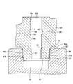
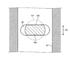
- FIG. 6 is a schematic diagram showing a relative position between the inner member and the radial pin.
- FIG. 7 is a perspective view showing a schematic configuration of a seal sleeve of the seal unit.
- FIG. 8 is a top view showing a schematic configuration of a plurality of divided sleeves of the support sleeve of the pin support unit.
- FIG. 9 is a top view showing a schematic configuration of the split sleeve of the support sleeve.
- FIG. 10 is an explanatory diagram illustrating an example of a method for mounting the fixing device.
- FIG. 11 is an explanatory diagram illustrating an example of a method for mounting the fixing device.
- FIG. 12 is an explanatory diagram illustrating an example of a method for mounting the fixing device.
- FIG. 13 is a schematic diagram illustrating a schematic configuration of another example of the fixing device.
- FIG. 14 is a cross-sectional view showing a schematic configuration in a state where the fixing device is removed from the outer member and the inner member.
- FIG. 15 is a top view showing a schematic configuration of a support sleeve of the pin support unit.
- FIG. 16 is a front view showing a schematic configuration of a support sleeve of the pin support unit.
- FIG. 17 is an explanatory diagram illustrating an example of a method of mounting the fixing device.
- FIG. 18 is an explanatory diagram illustrating an example of a method for mounting the fixing device.
- FIG. 19 is a perspective view showing a schematic configuration of another example pin support unit.
- FIG. 20 is a perspective view showing a schematic configuration of a pin support unit of another example.
- this invention is not limited by this embodiment, and when there are two or more embodiments, what comprises combining each embodiment is also included.
- this embodiment demonstrates by the case where a rotary machine is used as a steam turbine, it is not limited to this.
- the rotating machine can be a gas turbine, a compressor, or the like.
- the fixing device can be used in various places where it is necessary to fix parts of a stationary part (a part that does not rotate) of the rotating machine.
- the fixing device is located on the outer side and the inner side in the radial direction of the stationary body of the rotating machine, such as the outer casing, inner casing, blade ring, dummy ring of the steam turbine, and the blade ring, casing of the compressor of the gas turbine. Applicable to members placed in relationship.
- FIG. 1 is a partial cross-sectional view showing a schematic configuration of a steam turbine having a fixing device according to an embodiment of the present invention.
- the steam turbine 10 shown in FIG. 1 supplies steam from the axial center side of the steam turbine 10, and the steam flows toward both ends in the axial direction and is discharged to the outside from both ends in the axial direction.
- the steam turbine 10 includes a rotor 16, a plurality of moving blades 30 connected to the rotor 16, an inner casing 34 disposed on the outer periphery of the moving blade 30, and an outer casing disposed outside the inner casing 34. 36, a steam inlet 40 for supplying steam to the internal casing 34, and a plurality of stationary blades 42 disposed inside the internal casing 34.
- a plurality of moving blades 30 connected to the rotor 16 and a plurality of stationary blades 42 arranged inside the internal casing 34 are alternately arranged.
- the inner casing 34 may be separated into an outer member 35 a fixed to the outer casing 36 and an inner member 35 b connected to the stationary blade 42.
- the outer member 35a can also be referred to as an inner casing
- the inner member 35b can also be referred to as a blade ring.
- the steam turbine 10 is provided with a fixing device 90 at each of a connecting portion between the inner casing 34 and the outer casing 36 and a connecting portion between the inner member 35b and the outer member 35a.
- the steam supplied from the steam inlet 40 passes through a region where the moving blades 30 and the stationary blades 42 are alternately arranged between the internal casing 34 and the rotor 16.
- the rotor 16 is rotated by rotating the moving blade 30 with the force of the passing steam.
- FIG. 2 is a sectional view conceptually showing the fixed unit of the steam turbine shown in FIG.
- the members of the two stationary parts fixed by the fixing device 90 are collectively referred to as an annular member 50.
- the annular member 50 includes an inner member 51 and an outer member 60.
- the inner member 51 and the outer member 60 are annular members, and the inner member 51 is disposed inside the outer member 60.
- the inner member 51 corresponds to the inner casing 34
- the outer member 60 corresponds to the outer casing 36.
- the inner member 51 corresponds to the inner member 35b
- the outer member 60 corresponds to the outer member 35a.
- the inner member 51 has an inner member upper half 52 and an inner member lower half 54.
- the inner member 51 is an end surface of the inner member upper half 52 in the circumferential direction (rotation direction) 20 and an end surface of the inner member lower half 54 in the circumferential direction (rotation direction) 20, that is, the inner member 51 is the inner member upper half 52.
- the split surface of the inner member lower half 54 come into contact with each other.
- the side surface is a surface seen when the steam turbine 10 is viewed from the vertical direction.
- the outer member 60 has an outer member upper half 62 and an outer member lower half 64. The outer member 60 is in contact with a flange provided on the side surface of the outer member upper half 62 and a flange provided on the side surface of the outer member lower half 64.
- the fixing unit 70 including the fixing device 90 fixes the inner member 51 and the outer member 60. That is, it fixes so that the relative position of each part of the inner member 51 and the outer member 60 may not change.
- the fixing unit 70 includes an outer member fixing device 72 and a fixing device 90. Note that the fixing unit 70 may further include a device that fixes the upper half and the lower half of the inner member, and a device that adjusts the relative position.
- the outer member fixing device 72 fixes the outer member upper half 62 and the outer member lower half 64.
- the outer member fixing device 72 includes a screw 74 inserted into a flange where the outer member upper half 62 and the outer member lower half 64 are in contact, and nuts 76 and 78 screwed into the screw 74.
- the outer member fixing device 72 clamps the outer member upper half 62 and the outer member lower half 64 by clamping and tightening the screws 74 inserted into the flanges with nuts 76 and 78.
- the fixing device 90 fixes the relative position of the inner member 51 and the outer member 60 in the rotation direction of the rotor 16. That is, the rotation of the outer member 60 with respect to the inner member 51 is suppressed, and the rotation of the inner member 51 with respect to the outer member 60 is suppressed.
- the fixing device 90 is inserted into a through-hole 66 formed in the outer member upper half 62 and a recess 56 formed at a position visible when viewed from the outside of the through-hole 66 in the inner member upper half 52.
- the recess 56 is formed in a part in the rotation direction.
- the fixing device 90 When the fixing device 90 is inserted into the through-hole 66 and the concave portion 56, and a force that causes the inner member 51 and the outer member 60 to rotate relative to the rotation direction of the rotor 16 acts, the rotation direction of the fixing device 90.
- the end surface of the contact hole is in contact with the through hole 66 and the recess 56. Accordingly, the fixing device 90 suppresses the inner member 51 and the outer member 60 from rotating relatively in the rotation direction of the rotor 16.
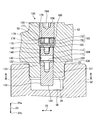
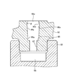
- FIG. 3 is a cross-sectional view illustrating a schematic configuration of the fixing device.
- 4 is a cross-sectional view taken along line AA in FIG.
- the fixing device 90 includes a radial pin 102 and a pin support unit 105, and is inserted into the through hole 66 and the recess 56.
- the radial direction of the rotor 16 that is the rotating portion of the steam turbine 10 is referred to as the radial direction of the rotor.
- the radial direction of the rotor is the radial direction of the steam turbine and is the radial direction of the rotating machine indicating the radial direction of the rotating shaft of the rotating machine.
- the through hole 66 has a diameter of the first surface 67, which is a portion on the radially inner side 24 b of the rotor (inside in the radial direction 24 of the rotor 16), on the radially outer side 24 a of the rotor (outside in the radial direction 24 of the rotor 16). It is smaller than the diameter of the second surface 68 which is a part.
- the boundary between the first surface 67 and the second surface 68 becomes a stepped portion 69.
- the stepped portion 69 is a surface that can be seen when viewed from the radially outer side of the rotor, that is, a surface that faces the radially outer side of the rotor.
- the diameter of the radially outer portion of the rotor is larger than the diameter of the radially inner portion of the rotor.
- the through-hole 66 is an outer hole that is a portion formed by the second surface 68 and a portion that is formed by the first surface 67 and is connected to the outer hole on the radially inner side of the rotor than the outer hole. It has an inner hole with a small diameter. Further, the through hole 66 has a thread groove 68 a formed in the second surface 68.
- the support unit insertion groove 80 is formed on the first surface 67 side from the position where the screw groove 68a of the second surface 68 is formed.
- the support unit insertion groove 80 is a recess formed in the second surface 68 and is formed on the entire circumference of the through hole 66 in the circumferential direction.
- the opening diameter of the support unit insertion groove 80 is larger than the portion of the second surface 68 adjacent to the radial direction of the rotor.
- the support unit insertion groove 80 has a shape in which the opening diameter is constant in the radial direction of the rotor.
- the end of the support unit insertion groove 80 on the radially outer side of the rotor serves as a load receiving surface 82 facing the radially inner side of the rotor.
- the recess 56 is formed in the groove 57 of the inner member upper half 52.
- the radial pin 102 is inserted into the through hole 66, and the end portion on the radially inner side of the rotor protrudes from the through hole 66 to the radially inner side of the rotor. In the radial pin 102, a portion protruding from the through hole 66 is inserted into the recess 56.
- the radial pin 102 is a columnar pin and has a shape in which the diameter of the outer peripheral surface 121 is substantially the same as or slightly smaller than the first surface 67 of the through hole 66.
- the radial pin 102 is provided with a flange 122 having a diameter larger than that of the outer peripheral surface 121 at an end portion that is radially outer of the rotor in a state of being inserted into the through hole 66.
- the flange 122 has a diameter larger than the diameter of the first surface 67 and smaller than the diameter of the second surface 68.
- the flange 122 is in contact with the step portion 69.
- the pin support unit 105 is disposed on the outer side in the radial direction of the rotor than the radial pin 102.
- the pin support unit 105 is disposed at a position where the support unit insertion groove 80 of the through hole 66 is formed in the radial direction of the rotor.
- the pin support unit 105 is a mechanism that suppresses a member disposed radially inward of the rotor including the radial pin 102 from moving out of the rotor radially outward and coming out of the through hole 66.
- the pin support unit 105 includes a support sleeve 170 and a spacer 172.
- the support sleeve 170 is a member that can be deformed in the radial direction of the through hole 66.
- a load receiving surface 177 which is an end surface on the radially outer side of the rotor (a surface facing the radially outer side of the rotating machine) is a load receiving surface of the support unit insertion groove 80 (a surface facing the radially inner side of the rotating machine). ) 82 and facing.
- the load receiving surface 177 at least partially overlaps the load receiving surface 82 in a direction orthogonal to the axial direction of the through-hole 66 (the radial direction of the rotor).
- the arc portion 174 has an inner peripheral surface 178 facing the spacer 172 and an outer peripheral surface 179 facing the inner peripheral surface of the support unit insertion groove 80.
- the support sleeve 170 protrudes radially inward from the support unit insertion groove 80 in the radial direction of the through hole 66, and at least partially overlaps the flange 122 of the radial pin 102.
- the support sleeve 170 is a ring arranged on the entire circumference of the through hole 66.
- the spacer 172 is a columnar member.
- the spacer 172 is disposed outside the support sleeve 170 in the radial direction of the rotor.
- the spacer 172 has a cylindrical shape, and the outer peripheral surface 180 faces the inner peripheral surface 178 of the support sleeve 170.
- the spacer 172 is formed with a screw groove to be screwed into the screw groove 68a of the through hole 66 at the end portion on the radially outer side of the rotor.
- the pin support unit 105 causes the outer peripheral surface 180 of the spacer 172 to face the inner peripheral surface 178 of the support sleeve 170, and the support sleeve 170 is disposed on the radially outer side of the through-hole 66 with respect to the outer peripheral surface 180. Is inserted into the support unit insertion groove 80. As a result, the load receiving surface 177 of the arc portion 174 and the load receiving surface 82 of the support unit insertion groove 80 overlap with each other in the radial direction of the through hole 66.
- the pin support unit 105 can fix the spacer 172 to the through hole 66 by screwing the spacer 172 into the screw groove 68a.
- the fixing device 90 fixes the relative position in the circumferential direction (rotation direction) of the rotor 16 between the outer member 60 and the inner member 51 with the radial pin 102.
- the fixing device 90 is a pin support unit 105 arranged on the outer side in the radial direction of the rotor with respect to the radial pin 102. The force generated when the radial pin 102 moves in the outer side in the radial direction of the rotor is applied to the outer member by the support sleeve 170. Transmit to half 62.
- the load receiving surface 177 is in contact with the load receiving surface 82, and the support sleeve 170 that is restricted from moving radially outward of the rotor is in contact with the radial pin 102.
- the radial pin 102 is prevented from moving out of the radial direction and coming out of the through hole 66.
- the fixing device 90 can fix the relative position in the rotation direction of the rotor 16 between the outer member 60 and the inner member 51.
- the fixing device 90 has the pin support unit 105 disposed therein, and the load receiving surface 82 of the support unit insertion groove 80 provided in the through hole 66 and the load receiving surface 177 of the support sleeve 170 are brought into contact with each other, whereby the radial pin It can suppress that 102 moves to the radial direction outer side of a rotor.
- the pin support unit 105 is supported by the load receiving surface 82 of the upper half 62 of the outer member when a force directed radially outward of the rotor is applied to the support sleeve 170.
- the fixing device 90 has a simple structure, and can prevent the radial pin 102 from coming out radially outward of the rotor. Further, the fixing device 90 can suppress the buckling of the support sleeve 170 by restricting the radial position of the through hole 66 of the support sleeve 170 with the spacer 172, and the support sleeve 170 can withstand a large load. Can be in a state.
- the fixing member 90 installed in the steam turbine 10 is exposed to the radial pin 102 to the high-pressure steam inside the outer member 60. For this reason, the force which acts on the radial pin 102 and moves toward the outer side in the radial direction of the rotor becomes great.
- the fixing device 90 has a structure in which the support sleeve 170 is supported by the load receiving surface 82 formed on the outer member 60, so that the force acting on the radial pin 102 can be received, Since the movement of the radial pin 102 is restricted, the number of components can be reduced, and the apparatus can be made compact.
- FIG. 4 is a cross-sectional view illustrating a schematic configuration of the fixing device.
- FIG. 4 is a view as seen from a position corresponding to the cross section along line AA in FIG.
- FIG. 5 is a cross-sectional view showing a schematic configuration in a state where the fixing device is removed from the outer member and the inner member.
- FIG. 6 is a cross-sectional view taken along the line BB in FIG. 4 and is a schematic diagram showing a relative position between the inner member and the radial pin.
- FIG. 7 is a perspective view showing a schematic configuration of a seal sleeve of the seal unit.
- FIG. 8 is a top view showing a schematic configuration of a support sleeve of the pin support unit.
- FIG. 9 is a top view showing a schematic configuration of the split sleeve of the support sleeve.
- the fixing device 100 includes a radial pin 102, a seal unit 104, a pin support unit 105, a lid member 106, and liners 108 and 109. Inserted.
- the through-hole 66 has a diameter of the first surface 67 that is a portion on the radially inner side 24 b of the rotor (inner side in the radial direction 24 of the rotor 16). It is smaller than the diameter of the second surface 68 which is a portion of the outer side 24a (outer side in the radial direction 24 of the rotor 16). In the through hole 66, the boundary between the first surface 67 and the second surface 68 becomes a stepped portion 69.
- the stepped portion 69 is a surface that can be seen when viewed from the radially outer side of the rotor, that is, a surface that faces the radially outer side of the rotor.
- the diameter of the radially outer portion of the rotor is larger than the diameter of the radially inner portion of the rotor.
- the through-hole 66 is connected to the outer hole, which is a part formed by the second surface 68, and the outer hole, which is a part formed by the first surface 67, on the inner side in the radial direction of the rotor. With a small inner hole.
- the through hole 66 has a thread groove 68 a formed in the second surface 68.
- the support unit insertion groove 80 is formed on the first surface 67 side from the position where the screw groove 68a of the second surface 68 is formed.
- the support unit insertion groove 80 is a recess formed in the second surface 68 and is formed on the entire circumference of the through hole 66 in the circumferential direction.
- the opening diameter of the support unit insertion groove 80 is larger than the portion of the second surface 68 adjacent to the radial direction of the rotor.
- the inner peripheral surface 84 of the support unit insertion groove 80 has a shape in which the opening diameter is constant in the radial direction of the rotor.
- the inner peripheral surface 84 is a surface in which the line in the rotor radial direction is perpendicular to the radial direction of the through hole 66.
- the end of the support unit insertion groove 80 on the radially outer side of the rotor serves as a load receiving surface 82 facing the radially inner side of the rotor.
- the end portion on the radially inner side of the rotor becomes a stepped portion 86 facing the radially outer side of the rotor.
- the load receiving surface 82 of this embodiment is a surface orthogonal to the radial direction of the rotor.
- the angle ⁇ formed by the load receiving surface 82 and the surface (circumferential surface) on the radially inner side of the rotor from the load receiving surface 82 is 90 degrees.
- the concave portion 56 is formed in the groove portion 57 of the inner member upper half 52.
- the groove part 57 is a groove formed on the entire circumference in the rotation direction. That is, the groove part 57 is formed in both the inner member upper half 52 and the inner member lower half 54, and the respective groove parts are connected to form a groove formed on the entire circumference.
- a convex portion 65 provided in a portion where the through hole 66 of the outer member upper half 62 of the outer member 60 is formed is inserted.
- the convex portion 65 is a protrusion that protrudes inward in the radial direction of the rotor, is formed at a position facing the groove portion 57, and is formed on the entire circumference in the rotational direction in the same manner as the groove portion 57.
- the groove portion 57 and the convex portion 65 are in contact with a surface 57 a that is a contact surface on the high-pressure steam space 25 side, that is, a space side through which higher-pressure steam flows, and serves as a seal surface.
- the space closer to the steam inlet 40 than the seal surface where the surfaces 57a and 65a are in contact is the high-pressure steam space 25, and the axial direction 22 is greater than the seal surface where the surfaces 57a and 65a are in contact.
- the space on the end side becomes a low-pressure steam space 26 whose pressure is lower than that of the high-pressure steam space 25.
- the groove part 57 and the convex part 65 should just contact
- the surface 57b, 65b on the opposite side to the sealing surface in the axial direction 22 has a part or all of the circumferential direction. It does not have to be.
- the radial pin 102 is inserted into the through hole 66 in the same manner as the radial pin 102 of the fixing device 100, and the end portion on the radially inner side of the rotor protrudes from the through hole 66 to the radially inner side of the rotor.
- a portion protruding from the through hole 66 is inserted into the recess 56.
- the radial pin 102 is a columnar pin and has a shape in which the diameter of the outer peripheral surface 121 is substantially the same as or slightly smaller than the first surface 67 of the through hole 66.
- the radial pin 102 is provided with a flange 122 having a diameter larger than that of the outer peripheral surface 121 at an end portion that is radially outer of the rotor in a state of being inserted into the through hole 66.
- the flange 122 has a diameter larger than the diameter of the first surface 67 and smaller than the diameter of the second surface 68.
- the flange 122 is in contact with the step portion 69.
- the radial pin 102 has a screw hole 124 formed on the surface on which the flange 122 is formed. A tool is inserted into the screw hole 124 when the radial pin 102 is inserted or removed.
- the radial pin 102 is provided with a notch surface 126 at a part of the radially inner end of the outer peripheral surface 121 of the rotor.
- the radial pin 102 has a shape in which the diameter of the outer peripheral surface 121 is wider than the width of the recess 56 in the rotation direction.
- the radial pin 102 can be inserted into the recess 56 at the radially inner end of the rotor by providing the notch surface 126.
- the radial pin 102 can have the width in the circumferential direction 20 substantially the same as the width of the recess 56 by forming the notch surface 126.
- the notch surfaces 126 are provided at both ends in the circumferential direction 20, but one may be used. Further, the notch surfaces 126 provided at both ends in the rotational direction may have an asymmetric shape with respect to the axis of the outer peripheral surface 121. In the present embodiment, the notch surface 126 is provided in the radial pin 102. However, as another example, a structure in which the radial pin 102 is adjusted with respect to the width of the concave portion 56 may be fitted. .
- the seal unit 104 is inserted into the through-hole 66 and disposed on the radial direction outer side of the radial pin 102 on the rotor.
- the seal unit 104 supports the radial pin 102 from the outside in the radial direction of the rotor and suppresses the movement to the outside in the radial direction of the rotor.
- the seal unit 104 seals, that is, closes, the through hole 66. Specifically, the seal unit 104 contacts the inner peripheral surface of the through hole 66 along the radial direction of the rotor and seals the through hole 66.
- the seal unit 104 includes a seal sleeve 112 and a seal insertion member 114.
- the seal sleeve 112 is a cylindrical member along the through-hole 66, in this embodiment, a cylindrical member.
- the seal sleeve 112 has a shape in which the diameter of the outer peripheral surface is smaller than the second surface 68 of the through hole 66.
- the seal sleeve 112 has a tapered shape in which the diameter of the inner peripheral surface 130 becomes smaller toward the inner side in the radial direction of the rotor.
- the seal insertion member 114 is a columnar member.
- the seal insertion member 114 is disposed outside the seal sleeve 112 in the radial direction of the rotor.
- the seal insertion member 114 has a tapered shape in which the diameter of the outer peripheral surface 140 becomes smaller toward the inner side in the radial direction of the rotor.
- the inclination angle of the outer peripheral surface 140 with respect to the radial direction of the rotor is substantially the same as the inclination angle of the inner peripheral surface 130 of the seal sleeve 112 with respect to the radial direction of the rotor. “Substantially the same” means that there is no difference in angle other than errors that occur during manufacturing.
- the seal insertion member 114 has a screw hole 142 formed on a surface that is radially outward of the rotor.
- the seal unit 104 has the above-described structure.
- the seal sleeve 112 is inserted into the seal sleeve 112 from the outer side in the radial direction of the rotor, and the inner peripheral surface 130 and the outer peripheral surface 140 are brought into contact with each other. Is expanded outward in the radial direction of the rotor, thereby bringing the seal sleeve 112 and the through hole 66 into contact with each other.
- the seal unit 104 seals the through hole 66 by filling the gap between the seal sleeve 112 and the seal insertion member 114 and the gap between the seal sleeve 112 and the through hole 66.
- the pin support unit 105 is disposed outside the seal unit 104 in the radial direction of the rotor.
- the pin support unit 105 is disposed at a position where the support unit insertion groove 80 of the through hole 66 is formed in the radial direction of the rotor.
- the pin support unit 105 is a mechanism that suppresses a member disposed radially inward of the rotor including the radial pin 102 from moving out of the rotor radially outward and coming out of the through hole 66.
- the pin support unit 105 includes a support sleeve 170 and a spacer 172.
- the support sleeve 170 has a plurality of divided sleeves 173, in this embodiment, six divided sleeves 173.
- the split sleeve 173 has an arc portion 174 and an overhang portion 176.
- the arc portion 174 has a plate shape that extends in the radial direction of the rotor and forms an arc along the support unit insertion groove 80 of the through hole 66.
- a load receiving surface 177 which is an end surface on the radially outer side of the rotor, is disposed so as to face the load receiving surface 82 of the support unit insertion groove 80.
- the load receiving surface 177 at least partially overlaps the load receiving surface 82 in a direction orthogonal to the axial direction of the through-hole 66 (the radial direction of the rotor).
- the arc portion 174 has an inner peripheral surface 178 facing the spacer 172 and an outer peripheral surface 179 facing the inner peripheral surface of the support unit insertion groove 80.
- the overhanging portion 176 is a fan-shaped member connected to the lower end of the arc portion 174 in the radial direction of the rotor, and protrudes toward the center of the through hole 66 with respect to the arc portion 174. In other words, the overhanging portion 176 is in contact with the arc portion 174 at the arc portion on the side having the larger fan-shaped diameter.
- the radially inner surface of the rotor faces the seal unit 104.
- the overhang portion 176 protrudes radially inward from the support unit insertion groove 80 in the radial direction of the through hole 66, and at least partially overlaps the liner 109.
- the overhang portion 176 only needs to overlap at least part of the radial pin 170.
- the support sleeve 170 becomes a ring arranged around the entire circumference of the through-hole 66 by combining the arc-shaped portion 174 and the overhanging portion 176 with the arc-shaped divided sleeve 173 along the circumferential direction of the through-hole 66.
- a gap is provided between the split sleeve 173 and the adjacent split sleeve 173 in the circumferential direction of the through hole 66.
- the support sleeve 170 can insert the split sleeve 173 into the support unit insertion groove 80 by providing a gap between the split sleeve 173 and the adjacent split sleeve 173.
- the support sleeve 170 preferably has an arc diameter of the outer peripheral surface 179 of the arc portion 174 that is the same as the diameter of the inner peripheral surface of the support unit insertion groove 80.
- the diameter of the arc of the inner peripheral surface 178 of the arc portion 174 is preferably the same as the diameter of the outer peripheral surface 180 of the spacer 172.
- the spacer 172 is a columnar member.
- the spacer 172 is disposed outside the support sleeve 170 in the radial direction of the rotor.
- the spacer 172 has a cylindrical shape, and the outer peripheral surface 180 faces the arc portion 174.
- the spacer 172 has a through hole 66 formed on the inner peripheral surface 178.
- the outer peripheral surface 180 of the spacer 172 faces the inner peripheral surface 178 of the arc portion 174 of the support sleeve 170, and the arc portion 174 of the support sleeve 170 is more radially outward of the through hole 66 than the outer peripheral surface 180.
- the arc portion 174 is inserted into the support unit insertion groove 80.
- the load receiving surface 177 of the arc portion 174 and the load receiving surface 82 of the support unit insertion groove 80 overlap with each other in the radial direction of the through hole 66.
- the lid member 106 is a columnar member and is inserted into the through hole 66.
- the lid member 106 is arranged on the outer side in the radial direction of the rotor than the pin support unit 105.
- the lid member 106 according to the present embodiment has an end surface on the radially outer side of the rotor arranged on the radially inner side of the rotor with respect to an end surface on the radially outer side of the rotor of the upper half 62 of the outer member, and is embedded in the through hole 66. ing.
- the lid member 106 is fixed to the outer member upper half 62 in which the through hole 66 is formed.
- the lid member 106 has a thread groove formed on the outer peripheral surface 162, and is screwed into the thread groove 68 a of the second surface 68 of the through hole 66.
- the lid member 106 has a hexagonal groove 164 formed on an end surface on the radially outer side of the rotor. The hexagonal groove 164 is inserted with a tool when the lid member 106 is inserted or removed.
- the liner 108 is disposed between the seal sleeve 112 and the radial pin 102.
- the liner 108 is a ring-shaped member in which a cylindrical hole 150 is formed.
- the liner 108 is a member that adjusts the thickness of the seal unit 104 in the radial direction of the rotor.
- the liner 108 has a shape in which the diameter inside the rotor in the radial direction, that is, the diameter of the cylindrical hole 150 is smaller than the diameter of the inner peripheral surface 130 of the seal sleeve 112. That is, the liner 108 is wider in the radial direction than the seal sleeve 112.
- the liner 108 can contact the flange 122 of the radial pin 102 while supporting the seal sleeve 112, and the seal sleeve 112 is sandwiched between the radial pin 102 and the through hole 66, or the seal sleeve 112. Suppresses unintended deformation.
- the liner 108 has only to have a shape in which the outer diameter is larger than the outer diameter of the radial pin 102 and extends to the inner side of the outer diameter of the radial pin 102 in the radial direction of the radial pin 102. Obtainable.
- the liner 109 is disposed between the seal insertion member 114 and the support sleeve 170.
- the liner 109 is a ring-shaped member in which a cylindrical hole 150 is formed.
- the liner 109 is a member that adjusts the thickness of the seal unit 104 in the radial direction of the rotor.
- the fixing device 100 can fill the gap between the seal insertion member 114 and the support sleeve 170 with the liner 109 by arranging the liner 109 with the thickness adjusted between the seal insertion member 114 and the support sleeve 170.
- the liner 109 partially overlaps the seal insertion member 114 and partially overlaps the support sleeve 170 in the radial direction of the through-hole 66 (direction orthogonal to the radial direction of the rotor). That is, when the through-hole 66 is viewed from the radially outer side of the rotor, the liner 109 partially overlaps the seal insertion member 114 and partially overlaps the support sleeve 170.
- the liner 109 can contact the flange of the seal insertion member 114 while supporting the support sleeve 170. Therefore, the liner 109 can transmit a force radially outward of the rotor from the seal insertion member 114 toward the support sleeve 170 to the support sleeve 170 from the seal insertion member 114.
- the fixing device 100 fixes the relative position in the rotation direction of the rotor 16 between the outer member 60 and the inner member 51 with the radial pin 102.
- the fixing device 100 seals the through-hole 66 with a seal unit 104 disposed on the radially outer side of the rotor with respect to the radial pin 102.
- the fixing device 100 is a pin support unit 105 disposed on the radially outer side of the rotor with respect to the radial pin 102 and the seal unit 104, and the force generated when the radial pin 102 and the seal unit 104 move to the radially outer side of the rotor. Is transmitted to the upper half 62 of the outer member by the support sleeve 170.
- the load receiving surface 177 is in contact with the load receiving surface 82, so that the support sleeve 170 that is restricted from moving radially outward of the rotor is connected to the seal unit 104 via the liner 109.
- the contact prevents the radial pin 102 and the seal unit 104 from moving outward in the radial direction and coming out of the through hole 66.
- the fixing device 100 prevents the spacer 172 of the pin support unit 105 from moving outward in the radial direction of the rotor and coming out of the through hole 66 by the lid member 106.
- the fixing device 100 can fix the relative position in the rotation direction of the rotor 16 between the outer member 60 and the inner member 51 while sealing the through hole 66.
- the pin support unit 105 is disposed, and the load receiving surface 82 of the support unit insertion groove 80 provided in the through hole 66 and the load receiving surface 177 of the support sleeve 170 are brought into contact with each other. It is possible to suppress the seal unit 104 from moving outward in the radial direction of the rotor.
- the pin support unit 105 is supported by the load receiving surface 82 of the upper half 62 of the outer member when a force directed radially outward of the rotor is applied to the support sleeve 170.
- the fixing device 100 can reduce the load applied to the lid member 106, and the lid member 106 can have a simple structure. Further, the fixing device 100 can suppress the buckling of the support sleeve 170 by restricting the radial position of the through hole 66 of the support sleeve 170 with the spacer 172, and the support sleeve 170 can withstand a large load. Can be in a state.
- the fixing device 100 fixes the lid member 106 to the outer member 60 by screwing the lid member 106 with a screw structure while sealing the sealing unit 104 by inserting and closing each member. Thereby, the fixing device 100 can be fixed without welding. Further, the fixing device 100 can be easily attached to and detached from the annular member 50. Further, the fixing device 100 has a seal structure in which the seal sleeve 112 of the seal unit 104 disposed inside the through hole 66 is deformed by the seal insertion member 114 and brought into contact with the inner peripheral surface of the through hole 66 along the radial direction of the rotor. By doing so, sealing can be performed even in a narrow place where the diameter of the through hole 66 cannot be increased.
- the outer member 60 and the inner member 51 are fixed with the radial pin 102 and sealing with the seal unit 104, the outer member is maintained while maintaining the sealing performance even when the centers of the recess 56 and the through hole 66 do not coincide with each other.
- 60 and the inner member 51 can be fixed.
- the seal unit 104 has a structure in which the seal insertion member 114 is pushed into the seal sleeve 112 and sealed, even if the center of each member is shifted at the time of insertion, the relative position moves in the matching direction. Sex can be made higher.
- the fixing device 100 includes the seal unit 104 and the radial pin 102, the axial center of the through hole at the position where the seal unit 104 is inserted, that is, the axial center of the cylindrical through hole formed by the second surface 68. Even if the axial center of the through hole at the position where the radial pin 102 is inserted, that is, the axial center of the cylindrical through hole formed by the first surface 67 is displaced, the seal unit 104 is moved relative to the radial pin 102. Is movable in the radial direction, the seal sleeve 112 can be uniformly expanded. Therefore, since the accuracy of the axial center of the through hole may be low, it is easy to manufacture the through hole.
- the fixing device 100 can further reduce the gap between the seal unit 104 and the pin support unit 105 by disposing the liner 109, and preferably transmit the force from the seal unit 104 to the pin support unit 105. Can do. Further, by providing the liner 109, the position of the end portion on the radially inner side of the rotor of the pin support unit 105 can be set to a fixed position. Thereby, the pin support unit 105 can be more reliably inserted into the support unit insertion groove 80.
- the fixing device 100 can further stably support the seal sleeve 112 by the liner 108 by disposing the liner 108, and the shaft center of the through hole on the radially inner side of the rotor and the seal sleeve 112 are disposed.
- the seal sleeve 112 can be uniformly expanded even when there is a deviation in the position of the axial center of the through hole on the radially outer side of the rotor. Further, by supporting the seal sleeve 112 with the liner 108, it is possible to prevent the seal sleeve 112 from entering and deforming into the gap between the flange 122 of the radial pin 102 and the through hole. Therefore, since the accuracy of the axial center of the through hole may be low, it is easy to manufacture the through hole.
- the liner 108 is provided between the radial pin 102 and the seal unit 104, and the seal sleeve 112 is supported by the liner 108, so that the seal sleeve 112 is sandwiched between the radial pin 102 and the through hole 66. Can be prevented.
- the seal sleeve 112 can be thinned, and the seal sleeve 112 can be easily deformed.
- the sealing performance between the seal sleeve 112 and the through hole 66 and between the seal sleeve 112 and the seal insertion member 114 can be enhanced. Sealability can be increased.
- the fixing device 100 can easily adjust the position in the radial direction of the rotor, that is, the depth direction of the through hole 66 by providing the liner 108. That is, since the thickness of the liner 108 can be adjusted with a shim or the like, the position in the depth direction of the through hole 66 of the seal sleeve 112 can be set to a constant position regardless of the shape of the radial pin 102.
- the fixing device 100 can be embedded in the through-hole 66, the fixing member 100 can be provided even in the case where there is another member on the outer peripheral surface side of the outer member 60 and there is a restriction on the available space.
- the fixing device 100 is a member disposed radially inward of the rotor by providing an overhanging portion 176 that protrudes in the center of the through hole 66 from the arc portion 174 on the radially inner side of the rotor of the split sleeve 173. And more reliably. For this reason, the split sleeve 173 is preferably provided with the overhang portion 176, but may not be provided.
- the screw groove is formed. It is not limited to that. Any tool can be used as long as the tool can be stopped and the hole can be rotated or hooked. Although it becomes difficult to perform attachment and removal, there is no need to have a hole for contacting the tool with the surface of the radial pin 102, the seal insertion member 114, and the lid member 106 formed on the radially outer side of the rotor in order to save processing. .
- the hexagonal groove 164 is formed in the lid member 106 of the fixing device 100, but the present invention is not limited to this.
- a position for attaching the tool may be provided in addition to the screw hole.
- the lid member 106 may be provided with a hexagonal protrusion on the radially outer side of the rotor where the outer peripheral surface is provided. By providing the protrusion, the lid member 106 can be rotated with a tool such as a hexagon wrench.
- the fixing device 100 may not include the liner 108. That is, the fixing device 100 may not be provided with the liner 108, and the seal sleeve 112 of the seal unit 104 may be in direct contact with the radial pin 102. Further, the fixing device 100 may not include the liner 109. That is, in the fixing device 100, the liner 109 may not be provided, and the support sleeve 170 of the pin support unit 105 may be in direct contact with the seal insertion member 114 of the seal unit 104.
- the seal unit 104 is provided between the radial pin 102 and the pin support unit 105 so that the pin support unit 105 causes the seal unit 104 and the radial pin 102 to move in the radial direction of the rotor.
- the radial pin 102 can be supported while the sealing performance by the seal unit 104 is maintained.
- the seal unit 104 is preferably provided between the radial pin 102 and the pin support unit 105, but the position where the seal mechanism is provided is not limited thereto.
- the fixing device 100 may provide a seal ring at a contact portion between the lid member 106 and the outer member upper half 62 as a sealing mechanism.
- the fixing device 100 may seal the contact surface between the radial pin 102 and the through hole 66 by a sealing mechanism.
- a sealing mechanism may be provided separately from the fixing device 100 without providing the fixing device 100 with a sealing mechanism.
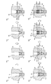
- FIG. 10 is an explanatory diagram illustrating an example of a method for mounting the fixing device.
- 11 and 12 are explanatory diagrams illustrating an example of a method for mounting the fixing device, respectively.
- the assembly method of a rotating machine can be used when assembling the rotating machine after disassembling the rotating machine for maintenance, or when manufacturing the rotating machine.
- this embodiment demonstrates as an assembly method of a rotary machine, the mounting method of a fixing device is applicable also to the manufacturing method of a rotary machine.
- the process shown in FIG. 10 can be executed by an operator performing work using a tool or a machine.
- the operator inserts the radial pin 102 into the through hole 66 of the outer member upper half 62 (step S12).
- the operator confirms the relative position between the through-hole 66 and the recess 56, and forms the notch surface 126 in the radial pin 102 based on the confirmed result.
- the tip of the radial pin 102 can be inserted into the recess 56, and the tip of the radial pin 102 is fitted into the recess 56 in the rotation direction of the rotor 16.
- Step S14 the operator inserts the liner 108 into the through hole 66 in which the radial pin 102 has been inserted (Step S14), inserts the seal sleeve 112 (Step S16), and then inserts the seal insertion member 114 (Step S14). S18).
- the operator uses the jig to manage the insertion amount and the pushing force (the torque to be rotated when using the jig inserted into the thread groove), and to move the seal insertion member 114 radially inward of the rotor. Push into.
- the seal insertion member 114 can be appropriately pushed into the seal sleeve 112 of the seal unit 104, and the through hole 66 can be sealed with the seal unit 104.
- the radial pin 102, the liner 108, and the seal unit 104 are inserted into the insertion hole 66.
- step S20 the operator inserts the liner 109 into the through hole 66 in which the seal unit 104 is inserted.
- the operator inserts the liner 109 having a thickness such that the end surface on the radially outer side of the rotor of the liner 109 coincides with the end surface on the radially inner side of the rotor of the support unit insertion groove 80.
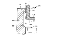
- the worker arranges the support sleeve 170 in the support unit insertion groove 80 of the through hole 66 in which the liner 109 is inserted (step S22). Specifically, as shown in FIG. 11, the dividing sleeve 173 is moved inward in the radial direction of the rotor as indicated by an arrow 194 and moved to a position where it comes into contact with the liner 109. Thereafter, the split sleeve 173 is moved radially outward of the through-hole 66 as indicated by an arrow 196 and inserted into the support unit insertion groove 80, the outer peripheral surface 179 faces the inner peripheral surface 84, and the load receiving surface 177 is It faces the load receiving surface 82.
- the operator repeats the above operation, inserts all the divided sleeves 173 into the support unit insertion grooves 80, and causes the load receiving surface 177 to face the load receiving surface 82. Thereby, the division sleeve 173 is arranged on the entire circumference of the support unit insertion groove 80.
- step S24 the operator inserts the spacer 172 into the through hole 66 in which the support sleeve 170 is disposed (step S24). Specifically, as shown in FIG. 12, a spacer 172 is inserted on the inner peripheral surface 178 side of the arc portion 174 of the split sleeve 173 so that the inner peripheral surface 178 and the outer peripheral surface 180 face each other.
- the operator inserts the lid member 106 into the through hole 66. Specifically, the screw groove of the lid member 106 is screwed into the screw groove of the through hole 66. At this time, the operator can appropriately push the spacer 172 of the pin support unit 105 by setting the pushing position of the lid member 106 and the tightening torque to predetermined values. The operator fixes the lid member 106 to the outer member upper half 62 by inserting the lid member 106 into the through hole 66 (step S26).
- the worker can easily attach the fixing device 100 to the annular member 50 by installing the fixing device 100 as described above. Thereby, the annular member 50 can be easily assembled without rotating in the rotation direction without using welding.
- the inner peripheral surface 84 of the support unit insertion groove 80 is positioned at the end portion in the radial direction of the rotor with respect to the second surface (outer hole inner peripheral surface) 68 of the through hole 66.
- it is possible to improve the workability by forming a concave shape so as to be a surface perpendicular to the radial direction of the rotor.
- the position of the support sleeve 170 using the liner 109 can be easily adjusted, and the support sleeve 170 can be easily adhered to the support unit insertion groove 80 and can be easily installed. It is possible to easily transmit the compression force.
- the fixing device assembling method can process the through hole so that the fixing device 100 can be mounted when the currently mounted fixing device is not the fixing device of the present embodiment.
- the second surface 68 is formed by expanding a part of the diameter on the radially outer side of the rotor, and the thread groove 68a is formed.
- the through hole 66 is formed.
- the support unit insertion groove 80 is formed on the formed second surface 68 thereafter.
- the through hole By machining the through hole, it can be remodeled into a hole in which the fixing device 100 can be attached.
- the modification of the through hole can be performed on the outer member upper half 62 placed during inspection of the apparatus provided with the annular member. Thereby, remodeling can be performed without interfering with other work. That is, modification can be performed without affecting the construction period as a whole.
- the through hole 66 of the present embodiment can be formed even in a state where the through hole is not formed in the outer member upper half 62.
- the fixing device 100 uses the lid member 106 while maintaining the sealing performance of the seal unit 104 even when the axis of the first surface 67 of the through hole 66 and the axis of the second surface 68 are deviated.
- the seal unit 104 can be supported so as not to come off.
- the function as the fixing device 100 can be maintained even when the hole connecting process is performed and the hole axis is shifted. For this reason, it is not necessary to perform the axial alignment of the holes with high accuracy, and the processing is simplified.
- FIG. 13 is a schematic diagram illustrating a schematic configuration of another example of the fixing device.
- FIG. 14 is a cross-sectional view showing a schematic configuration in a state where the fixing device is removed from the outer member and the inner member.
- FIG. 15 is a top view showing a schematic configuration of a support sleeve of the pin support unit.
- FIG. 16 is a front view showing a schematic configuration of a support sleeve of the pin support unit.
- 17 and 18 are explanatory diagrams showing an example of a method for mounting the fixing device, respectively.
- the fixing device 100a includes a radial pin 102, a seal unit 104a, a pin support unit 105a, a lid member 106a, and a liner 109, and is inserted into the through hole 66a and the recess 56.
- the radial pin 102 and the liner 109 of the fixing device 100a have the same configuration as each part of the fixing device 100.
- the support unit insertion groove 80a is formed on the first surface 67 side from the position where the screw groove 68a of the second surface 68 is formed.
- the support unit insertion groove 80a is a recess formed in the second surface 68, and is formed on the entire circumference of the through hole 66a in the circumferential direction.
- the support unit insertion groove 80a has an opening diameter larger than that of the second surface 68 adjacent to the rotor in the radial direction. That is, the inner peripheral surface 84a of the support unit insertion groove 80a has a tapered shape in which the diameter gradually increases toward the outer side in the radial direction of the rotor in the radial direction of the rotor.
- the inner peripheral surface 84a is an inclined surface.
- the end portion on the radially outer side of the rotor becomes a load receiving surface 82a facing the radially inner side of the rotor.
- the load receiving surface 82a of the present embodiment is a surface orthogonal to the radial direction of the rotor.
- the angle ⁇ formed by the load receiving surface 82a and the surface (circumferential surface, tapered surface) on the radially inner side of the rotor from the load receiving surface 82a is 90 degrees.
- the seal unit 104a is a seal ring, and is disposed between the flange 122 of the radial pin 102 and the stepped portion 69.
- the seal unit 104a is inserted into a groove formed on the surface of the flange 122 on the stepped portion 69 side.
- the seal unit 104a seals between the space on the first surface 67 side and the space on the second surface 68 side of the through hole 66a by sealing between the flange 122 and the stepped portion 69.
- the liner 109 is disposed between the radial pin 102 and the pin support unit 105a.
- the pin support unit 105a includes a support sleeve 170a and a spacer 172a.
- the support sleeve 170a has a cylindrical shape, and has a tapered shape in which the diameters of the inner peripheral surface 178a and the outer peripheral surface 179a become smaller toward the inner side in the radial direction of the rotor.
- a surface formed on the radially outer side of the rotor is a load receiving surface 177a.
- the load receiving surface 177a at least partially overlaps the load receiving surface 82a in a direction orthogonal to the axial direction of the through hole (the radial direction of the rotor).
- the radially inner surface of the rotor faces the seal unit 104.
- the support sleeve 170a protrudes inward in the radial direction from the support unit insertion groove 80a in the radial direction of the through hole 66, and at least partially overlaps the liner 109.
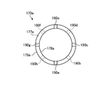
- the support sleeve 170a is formed with slits 190a, 190b, 190c, 190d, 190e, 190f, 190g, and 190h.
- the slits 190a, 190b, 190c, 190d, 190e, 190f, 190g, and 190h are arranged in this order in the circumferential direction of the cylindrical shape of the support sleeve 170a.
- the slit 190a and the slit 190h are also adjacent. It is formed along the axial direction of the cylindrical shape of the support sleeve 170a and the axial direction of the through hole 66a.
- each of the slits 190a, 190c, 190e, and 190g opens to the load receiving surface 177a, and the other end stops halfway.
- One end of each of the slits 190b, 190d, 190f, and 190h opens on the surface opposite to the load receiving surface 177a, and the other end stops halfway. That is, the support sleeve 170a has, in the circumferential direction of the cylindrical shape, a slit having one end opened to the load receiving surface 177a, a slit having one end opened to the surface opposite to the load receiving surface 177a, and Are formed alternately.
- the spacer 172a is a columnar member.
- the spacer 172a is disposed outside the support sleeve 170 in the radial direction of the rotor.
- the spacer 172 a has a cylindrical shape, and the outer peripheral surface 180 a faces the arc portion 174.
- the spacer 172a has a tapered shape in which the diameter of the outer peripheral surface 180a becomes smaller toward the inner side in the radial direction of the rotor.
- the inclination angle of the outer peripheral surface 180a with respect to the radial direction of the rotor is substantially the same as the inclination angle of the inner peripheral surface 178a of the support sleeve 170a with respect to the radial direction of the rotor.
- the inclination angle of the outer peripheral surface 180a with respect to the radial direction may be different from the inclination angle of the inner peripheral surface 178a of the support sleeve 170a with respect to the radial direction.
- the spacer 172a has a screw hole formed on a surface on the radially outer side of the rotor.
- the fixing device 100a can be assembled and manufactured by an installation process of the pin support unit 105a, an assembling method and a manufacturing method of the fixing device 100a.
- the worker places a support sleeve 170a in the through hole 66a in which the liner 109 is placed.
- the end surface on the radially inner side of the rotor of the support sleeve 170a is a flat surface 250 in which the center side of the through hole 66a is parallel to the load receiving surface 177a, and the inclined surface whose inner peripheral surface 84a side is inclined with respect to the load receiving surface 177a. 252.
- the inclined surface 252 is inclined so as to approach the load receiving surface 177a as it approaches the inner peripheral surface 84a.
- the support sleeve 170 a has a flat surface 250 in contact with the liner 109.
- the operator inserts the spacer 172a into the through hole 66a.
- the outer peripheral surface 180a of the spacer 172a is brought into contact with the inner peripheral surface 178a of the support sleeve 170a, and when the spacer 172a is further pushed, the support sleeve 170a is pushed outward in the radial direction of the through hole 66a.
- the gaps between the slits 190a, 190b, 190c, 190d, 190e, 190f, 190g, and 190h of the support sleeve 170a are widened, and the support sleeve 170a is deformed to the outer side in the radial direction of the through-hole 66a. . As shown in FIG.
- the pin support unit 105a is inserted into the support unit insertion groove 80a as a result of the support sleeve 170a being deformed radially outward of the through hole 66a, and the outer periphery 179a of the support sleeve 170a and the inner periphery of the pin support unit 105a.
- the surface 84a is in contact, and the load receiving surface 177a and the load receiving surface 82a of the support unit insertion groove 80a overlap each other in the radial direction of the through hole 66a.
- the end surface on the radially inner side of the rotor is deformed in conjunction with other portions, and the inclined surface 252 becomes the end surface on the liner 109 side.
- the liner 109 moves to the outer side in the radial direction of the rotor, it contacts the inclined surface 252.
- the inclined surface 252 is inclined with respect to the flat surface 250 at the same angle as the inclination angle of the taper after deformation of the support sleeve 170a.
- the lid member 106 a is fixed to the outer member upper half 62 with a bolt 240.
- the lid member 106a includes a plate portion 230 that closes the through hole 66a, and a projection portion 232 that protrudes from the plate portion 230 to the through hole 66a and contacts the spacer 172a.
- the plate portion 230 is larger than the through hole 66a and closes the entire surface of the through hole 66a.
- the lid member 106a is in contact with the surface of the outer member upper half 62 formed on the outer side in the radial direction of the rotor, with a portion larger than the through hole 66a of the plate portion 230.
- the bolt 240 is provided at a position in contact with the outer member upper half 62 of the plate portion 230, and is screwed into a screw hole provided in the outer member upper half 62.
- the lid member 106 a is provided with bolts 240 at four locations so as to surround the protrusion 232.
- the fixing device 100a forms the load receiving surface 82a facing the lower side in the radial direction of the rotor so that the pin support unit 105a can remove the rotor from the member on the lower side in the radial direction of the rotor. Even if a force directed radially outward is applied, the load receiving surface 177a can be supported by the load receiving surface 82a, and the rotor can be prevented from coming out radially outward.
- the fixing device 100a can be easily deformed by forming the slits 190a, 190b, 190c, 190d, 190e, 190f, 190g, and 190h even if the support sleeve 170a of the pin support unit 105a is formed of one member.
- the support sleeve 170a can be inserted into the support unit insertion groove 80a.
- the support sleeve 170a is deformed by forming slits 190a, 190b, 190c, 190d, 190e, 190f, 190g, and 190h parallel to the axial direction of the cylinder of the support sleeve 170a and the axial direction of the through hole 66a. It can be made easier. Further, the support sleeve 170a has slits 190a, 190b, 190c, 190d, 190e, 190f, 190g, and 190h that have open end surfaces (end surfaces in the axial direction) alternately in the circumferential direction of the cylindrical shape. Thus, the shape of the cylindrical shape can be easily deformed outward in the radial direction.
- FIG. 19 is a perspective view showing a schematic configuration of a support sleeve of a pin support unit of another example.
- a support sleeve 170b shown in FIG. 19 has a plurality of slits 192 formed therein. One end of the plurality of slits 192 is open at the end face.
- the support sleeve 170b preferably has a slit 192 opened on the side facing the load receiving surface 82a. As shown in the support sleeve 170b, a slit may be opened on the same end surface.
- the fixing member 100a sandwiches the support sleeve 170a between the support unit insertion groove 80a and the spacer 172a. As a result, deformation such as buckling of the support sleeve 170a can be prevented. Further, it is easy to apply the radial compressive force of the rotor to the support sleeve 170a, and it is possible to make it difficult for bending deformation to occur.
- the fixing device 100a can adjust the position of the support sleeve 170a by the liner 109.
- the fixing device 100a can closely attach the support sleeve 170a to the support unit insertion groove 80a by providing a partly inclined surface 252 on the radially inner surface of the rotor of the support sleeve 170a.
- the support sleeve 170a can be more closely attached to the liner 109 and the support unit insertion groove 80a, and only the compression force can be easily transmitted.
- the fixing device 100a sets the angle ⁇ formed by the load receiving surface 82a and the surface (peripheral surface, tapered surface) radially below the load receiving surface 82a to 90 degrees, so that the load receiving surface 82a and the load The receiving surface 177a can be more reliably brought into contact.
- the angle ⁇ formed is preferably 90 degrees, but may be an angle other than 90 degrees.
- the fixing device 100a is fixed to the outer member upper half 62 with the bolt 240 without providing a screw hole in the through hole 66a.
- the lid member 106 a may be fixed to the outer member upper half 62 using the bolt 240.
- the fixing device 100a can be installed even when the attachment space for the lid member is narrow by making the lid member 106a into a substantially rectangular shape having a short side direction and a long side direction.
- the number of the bolts 240 when the lid member is fastened with the bolts 240 is not particularly limited.
- the lid member 106 a may be provided with bolts 240 at six locations so as to surround the protrusion 232.
- the lid member 106a can be reliably fixed by the outer member upper half 62 although the fixing device becomes larger by increasing the number of bolts 240.
- FIG. 20 is a perspective view showing a schematic configuration of a support sleeve of another example pin support unit.
- the support sleeve 170c shown in FIG. 20 has an opening 194 formed in a part of a cylindrical cross section, and has a C-shaped cross section.
- the opening formed in the support sleeve 170c is formed from an end portion in the axial direction of the cylindrical shape.
- the spacer 172a can be pushed outward in the cylindrical radial direction similarly to the support sleeve 170a. Can be deformed.
- the support sleeve 170c In the case of the structure of the support sleeve 170c, the support sleeve 170c is compressed and deformed and inserted into the through hole 66a, and when reaching the support unit insertion groove 80a, it is deformed radially outward by a restoring force. May be.
- the pin support unit may not include the spacer when the support sleeve 170c is inserted into the support unit insertion groove 80a with a restoring force.
- the fixing device 100 is provided at the highest position in the rotation direction of the rotor, that is, at the upper end in the vertical direction.
- the fixing device 100 may be provided at any position in the rotation direction of the rotor 16.
- you may install a fixing device in the lowest position of an outer member, ie, the through-hole of the edge part of the perpendicular direction lower side. That is, the fixing device described above may be provided in the lower half of the outer member. Even when the fixing device is provided in the lower half of the outer member, the mounting method of the fixing device described above can be used, and it can be used for the manufacturing method and the assembling method of the rotating machine.
Landscapes
- Engineering & Computer Science (AREA)
- General Engineering & Computer Science (AREA)
- Mechanical Engineering (AREA)
- Turbine Rotor Nozzle Sealing (AREA)
Abstract
ラジアルピンの回転機械の径方向外側への移動を抑制することができ、かつ、簡単な構造の固定装置、蒸気タービン、回転機械の製造方法及び組立方法を提供する。固定装置は、外側部材の回転機械の径方向外側に開口する外側孔及び外側孔に連通し、外側孔よりも径が小さく、回転機械の径方向内側に開口する内側孔が形成され、外側部材の回転機械の径方向に貫通する貫通孔に挿入され、回転機械の径方向内側の一部が内側部材に形成された凹部に挿入され、内側孔の径よりも外径が大きいフランジ部を有するラジアルピンと、ラジアルピンよりも回転機械の径方向外側の外側孔に挿入され、回転機械の径方向外側に形成された面が、外側孔に形成され回転機械の径方向内側を向く面と貫通孔の径方向に重なり、かつ、ラジアルピンと貫通孔の径方向に重なるピン支持ユニットと、を有することを特徴とする。
Description
本発明は、回転機械の静止側の2つの部材の回転方向の相対位置を固定する固定装置、これを有する蒸気タービン、回転機械の製造方法及び回転機械の組立方法に関する。
回転機械としては、蒸気タービン、ガスタービン、圧縮機等がある。例えば、蒸気タービンは、外部車室と、外部車室内に設けられた内部車室と、内部車室に挿入されたロータと、ロータに多段にわたって配置された複数の動翼と、内部車室に多段にわたって配置された複数の静翼と、を有する。多段の動翼と静翼とは、ロータの軸方向に交互に配設されている。蒸気タービンは、蒸気が内部車室に入り、多段の静翼と動翼が配置されている空間に供給されることで、この多段の動翼を介してロータを回転させ、このロータに連結された発電機を駆動する。
ここで、回転機械は、外部車室と内部車室と静翼とを含む静止側(固定側)の部材(静止体)の、回転機械の回転方向、軸方向、水平方向等の相対位置を固定するために各種装置を設けている。例えば、特許文献1には、静止側の部材の、回転機械の回転方向における相対位置を固定する装置として、静翼を支持する翼環と翼環を支持する内車室との相対位置を固定する装置が記載されている。特許文献1に記載の装置は、内車室に形成された孔に挿入され、翼環に形成された凹部に先端が挿入されるラジアルピン(偏心ピン)を有する。ラジアルピンは、ピンを用いて内車室に固定されることで、内車室に対して固定される。また、特許文献1に記載の装置は、ラジアルピンの回転機械の径方向外側に蓋体を設け、蓋体をボルトで外車室に固定している。
特許文献1の固定装置は、ラジアルピンの回転機械の径方向外側に蓋体を配置し、蓋体をボルトで車室に固定することで、ラジアルピンが回転機械の径方向外側に移動することを規制している。このような構造の場合、ラジアルピンから蓋体に対し蓋体を回転機械の径方向外側へ移動させようとする力が作用するので、蓋体のボルト等の締結部材のサイズを大型化させる必要があり、蓋体を大型化せざるを得ない。つまり、ラジアルピンの回転機械の径方向外側への移動を規制する部材を小型化することが困難となる。
本発明は上述した課題を解決するものであり、外側部材及び内側部材に挿入されるラジアルピンの回転機械の径方向外側への移動を抑制することができ、かつ、簡単な構造の固定装置、蒸気タービン、回転機械の製造方法及び回転機械の組立方法を提供することを目的とする。
上記の目的を達成するための本発明は、回転機械の静止体の外側部材及び内側部材の周方向における相対位置を固定する固定装置であって、前記外側部材の前記回転機械の径方向外側に開口する外側孔、及び、前記外側孔に連通し、前記外側孔よりも径が小さく、前記回転機械の径方向内側に開口する内側孔が形成され、前記外側部材の前記回転機械の径方向に貫通する貫通孔に挿入され、前記回転機械の径方向内側の一部が前記内側部材に形成された凹部に挿入され、前記内側孔の径よりも外径が大きいフランジ部を有するラジアルピンと、前記回転機械の径方向外側の前記外側孔に挿入され、前記回転機械の径方向外側に形成された面が、前記外側孔に形成され前記回転機械の径方向内側を向く面と前記貫通孔の径方向に重なり、かつ、前記ラジアルピンと前記貫通孔の径方向に重なるピン支持ユニットと、を有することを特徴とする。
また、前記ピン支持ユニットは、前記回転機械の径方向外側に面が形成された支持スリーブと、前記支持スリーブの内側に配置され、前記支持スリーブの内周面と接するスペーサと、を有することが好ましい。
また、前記外側孔の内周面には前記外側孔の径方向に凹む支持ユニット挿入溝が形成され、前記支持ユニット挿入溝の前記回転機械の径方向外側に前記回転機械の径方向内側を向く面が形成され、前記回転機械の径方向内側を向く面と前記支持スリーブの前記回転機械の径方向外側に形成された面とが接し、かつ、前記支持スリーブの外周面が前記支持ユニット挿入溝と接することが好ましい。
また、前記支持スリーブは、前記貫通孔の周方向に分割された複数の分割スリーブを有することが好ましい。
また、前記支持スリーブは、スリットが形成された円筒形状であり、前記スペーサは、前記回転機械の径方向外側から内側に向かうにしたがって径が小さくなる形状であることが好ましい。
また、前記スリットは、前記支持スリーブの前記回転機械の径方向の外側の端面または内側の端面から前記回転機械の径方向に沿って形成されていることが好ましい。
また、前記ピン支持ユニットの前記回転機械の径方向外側に配置され、かつ、前記外側部材に固定される蓋部材を有することが好ましい。
また、前記支持スリーブの前記外周面が、前記外側孔の前記回転機械の径方向内側を向く面に対して垂直であることが好ましい。
また、前記ピン支持ユニットと前記ラジアルピンとの間に配置され、前記ピン支持ユニットと接するライナを有することが好ましい。
また、前記支持ユニット挿入溝には、前記支持スリーブの前記外周面と接し前記外側孔の径方向に垂直な面と、前記回転機械の径方向内側を向く面と対向する面とが形成されることが好ましい。
また、前記支持ユニット挿入溝には、前記支持スリーブの前記外周面と接し前記回転機械の径方向外側から内側に向かうにしたがって前記外側孔の径方向内側へ向かう面が形成されることが好ましい。
また、前記貫通孔に挿入され、前記ピン支持ユニットよりも前記回転機械の径方向内側で前記貫通孔をシールするシールユニットをさらに有することが好ましい。
また、前記シールユニットは、前記回転機械の径方向に沿って内周面の径が変化するシールスリーブと、前記シールスリーブに挿入され、前記シールスリーブの前記内周面と接する柱状の挿入部材と、を有し、前記シールスリーブの外周面が前記貫通孔と接し、前記シールスリーブの前記内周面と前記挿入部材とが接することが好ましい。
上記の目的を達成するための本発明は、蒸気タービンであって、上記のいずれかに記載の固定装置と、前記外側部材と、前記内側部材と、前記内側部材よりも前記回転機械の径方向内側に配置される回転体と、を有することを特徴とする。
上記の目的を達成するための本発明は、回転機械の静止体の外側部材及び内側部材の周方向における相対位置を固定し回転機械を製造する回転機械の製造方法であって、前記外側部材の前記回転機械の径方向外側に開口する外側孔、及び、前記外側孔に連通し、前記外側孔よりも径が小さく、前記回転機械の径方向内側に開口する内側孔が形成され、前記外側部材の前記回転機械の径方向に貫通する貫通孔に、前記内側孔の径よりも外径が大きいフランジ部を有するラジアルピンを挿入し、前記ラジアルピンの前記回転機械の径方向内側の端部を前記外側部材の前記回転機械の径方向内側に配置された前記内側部材に形成された凹部に挿入するステップと、前記回転機械の径方向外側の前記外側孔にピン支持ユニットを挿入し、前記ピン支持ユニットを前記ラジアルピンと前記貫通孔の径方向に重ね、かつ、前記ピン支持ユニットの前記回転機械の径方向外側に形成された面を、前記外側孔に形成され前記回転機械の径方向内側を向く面と前記貫通孔の径方向に重ねるピン支持ユニット設置ステップと、を有することを特徴とする。
また、前記ピン支持ユニットは、前記回転機械の径方向外側に面が形成された支持スリーブと、前記支持スリーブの内側に挿入されるスペーサと、を有し、前記ピン支持ユニット設置ステップは、前記支持スリーブの前記回転機械の径方向外側に形成された面を前記外側孔の前記回転機械の径方向内側を向く面と接する位置に配置するステップと、前記支持スリーブの内側に前記スペーサを挿入するステップと、を有することが好ましい。
また、前記ピン支持ユニットは、前記回転機械の径方向外側に面が形成された支持スリーブと、前記支持スリーブの内側に挿入されるスペーサと、を有し、前記ピン支持ユニット設置ステップは、前記支持スリーブを前記外側孔に配置するステップと、前記支持スリーブの内側に前記スペーサを挿入し、前記支持スリーブを前記貫通孔の径方向外側に移動させ、前記支持スリーブの前記回転機械の径方向外側に形成された面を、前記外側孔の前記回転機械の径方向内側を向く面と接する位置に移動させるステップと、を有することが好ましい。
上記の目的を達成するための本発明は、回転機械の静止体の外側部材及び内側部材の周方向における相対位置を固定し回転機械を製造する回転機械の組立方法であって、前記外側部材の前記回転機械の径方向外側に開口する外側孔、及び、前記外側孔に連通し、前記外側孔よりも径が小さく、前記回転機械の径方向内側に開口する内側孔が形成され、前記外側部材の前記回転機械の径方向に貫通する貫通孔に、前記内側孔の径よりも外径が大きいフランジ部を有するラジアルピンを挿入し、前記ラジアルピンの前記回転機械の径方向内側の端部を前記外側部材の前記回転機械の径方向内側に配置された前記内側部材に形成された凹部に挿入するステップと、前記回転機械の径方向外側の前記外側孔にピン支持ユニットを挿入し、前記ピン支持ユニットを前記ラジアルピンと前記貫通孔の径方向に重ね、かつ、前記ピン支持ユニットの前記回転機械の径方向外側に形成された面を、前記外側孔に形成され前記回転機械の径方向内側を向く面と前記貫通孔の径方向に重ねるピン支持ユニット設置ステップと、を有することを特徴とする。
本発明によれば、ピン支持ユニットを設けることで、外側部材及び内側部材に挿入されるラジアルピンの回転機械の径方向外側への移動を抑制することができ、かつ、簡単な構造とすることができる。
以下に添付図面を参照して、本発明の好適な実施形態を詳細に説明する。なお、この実施形態により本発明が限定されるものではなく、また、実施形態が複数ある場合には、各実施形態を組み合わせて構成するものも含むものである。例えば、本実施形態は、回転機械を蒸気タービンとした場合で説明するが、これに限定されない。回転機械は、ガスタービン、圧縮機等とすることもできる。固定装置は、回転機械の静止部(回転しない部分)の部品同士を固定する必要がある種々の箇所に用いることができる。固定装置は、蒸気タービンの外車室、内車室、翼環、ダミー環、また、ガスタービンの圧縮機の翼環、車室など、回転機械の静止体のうち半径方向外側と内側との位置関係に配置される部材に適用できる。
図1は、本発明の実施形態に係る固定装置を有する蒸気タービンの概略構成を示す部分断面図である。図1に示す蒸気タービン10は、蒸気タービン10の軸方向の中心側から蒸気を供給し、軸方向の両端のそれぞれに向かって蒸気が流れ、軸方向の両端から外部に排出される。蒸気タービン10は、ロータ16と、ロータ16に連結された複数の動翼30と、動翼30の外周に配置された内部車室34と、内部車室34の外側に配置された外部車室36と、内部車室34に蒸気を供給する蒸気入口部40と、内部車室34の内部に配置された複数の静翼42と、を有する。蒸気タービン10は、ロータ16に連結された複数の動翼30と、内部車室34の内部に配置された複数の静翼42とが交互に配置されている。また、内部車室34は、外部車室36に固定される外側部材35aと、静翼42に連結される内側部材35bとに分離されているものもある。なお、外側部材35aを内部車室、内側部材35bを翼環ということもできる。蒸気タービン10は、内部車室34と外部車室36との連結部及び内側部材35bと外側部材35aとの連結部のそれぞれに固定装置90が設けられている。
蒸気タービン10は、蒸気入口部40から供給された蒸気が、内部車室34とロータ16との間で動翼30と静翼42とが交互に配置されている領域を通過する。蒸気タービン10は、通過する蒸気の力で動翼30が回転されることで、ロータ16が回転する。
次に、図2を用いて、固定装置90を含む固定ユニット70について説明する。図2は、図1に示す蒸気タービンの固定ユニットを概念的に示す断面図である。固定装置90が、固定する2つの静止部の部材をまとめて、環状部材50という。環状部材50は、内側部材51と外側部材60と、を有する。内側部材51と外側部材60とは、環状の部材であり、内側部材51が外側部材60の内側に配置されている。ここで、内部車室34と外部車室36とを固定する固定装置90の場合、内側部材51が内部車室34に相当し、外側部材60が外部車室36に相当する。内部車室34の内側部材35bと外側部材35aとを固定する固定装置90の場合、内側部材51が内側部材35bに相当し、外側部材60が外側部材35aに相当する。
内側部材51は、内側部材上半52と内側部材下半54とを有する。内側部材51は、内側部材上半52の周方向(回転方向)20の端面と内側部材下半54の周方向(回転方向)20の端面と、つまり、内側部材51は、内側部材上半52と内側部材下半54の分割面が接触する。ここで、側面とは、蒸気タービン10を鉛直方向から見た場合に見える面である。外側部材60は、外側部材上半62と外側部材下半64とを有する。外側部材60は、外側部材上半62の側面に設けられたフランジと外側部材下半64の側面に設けられたフランジとが接触する。
固定装置90を含む固定ユニット70は、内側部材51と外側部材60とを固定する。つまり、内側部材51と外側部材60との各部の相対的な位置が変化しないように固定する。固定ユニット70は、外側部材固定装置72と、固定装置90と、を有する。なお、固定ユニット70は、内側部材の上半と下半とを固定する装置や、相対位置を調整する装置をさらに備えていてもよい。
外側部材固定装置72は、外側部材上半62と外側部材下半64を固定する。外側部材固定装置72は、外側部材上半62と外側部材下半64とが接触しているフランジに挿入されたねじ74と、ねじ74にねじ込まれたナット76、78である。外側部材固定装置72は、フランジに挿入されたねじ74をナット76、78で挟み込み、締め付けることで、外側部材上半62と外側部材下半64とを締結している。
固定装置90は、内側部材51と外側部材60とのロータ16の回転方向における相対位置を固定している。つまり、内側部材51に対して外側部材60が回転することを抑制し、外側部材60に対して内側部材51が回転することを抑制する。固定装置90は、外側部材上半62に形成された貫通孔66及び内側部材上半52の貫通孔66の外側から覗いた場合に見える位置に形成された凹部56に挿入されている。凹部56は回転方向の一部に形成されている。固定装置90は、貫通孔66及び凹部56に挿入されることで、内側部材51と外側部材60とがロータ16の回転方向に相対的に回転する力が作用した場合、固定装置90の回転方向の端の面が貫通孔66及び凹部56に接する。これにより、固定装置90は、内側部材51と外側部材60とがロータ16の回転方向に相対的に回転することを抑制する。
次に、図3を用いて、固定装置について説明する。図3は、固定装置の概略構成を示す断面図である。図4は、図2のA-A線断面図である。図3に示すように、固定装置90は、ラジアルピン102と、ピン支持ユニット105と、を有し、貫通孔66及び凹部56に挿入される。以下では、蒸気タービン10の回転部であるロータ16の径方向をロータの径方向という。ロータの径方向は、蒸気タービンの径方向であり、回転機械の回転軸の径方向を示す回転機械の径方向となる。貫通孔66は、ロータの径方向内側24b(ロータ16の径方向24における内側)の部分である第1面67の径が、ロータの径方向外側24a(ロータ16の径方向24における外側)の部分である第2面68の径よりも小さくなっている。貫通孔66は、第1面67と第2面68の境界が段差部69となる。段差部69は、ロータの径方向外側から覗いた場合に見える面、つまりロータの径方向外側を向く面である。段差部69は、ロータの径方向外側の部分の径がロータの径方向内側の部分の径よりも大きくなる。このように、貫通孔66は、第2面68で形成された部分である外側孔、及び、第1面67で形成された部分であって外側孔にロータの径方向内側で繋がり外側孔より径の小さな内側孔を有する。また、貫通孔66は、第2面68にねじ溝68aが形成されている。
また、貫通孔66は、第2面68のねじ溝68aが形成されている位置よりも第1面67側に、支持ユニット挿入溝80が形成されている。支持ユニット挿入溝80は、第2面68に形成された凹部であり、貫通孔66の周方向の全周に形成されている。支持ユニット挿入溝80は、第2面68のロータの径方向に隣接している部分よりも開口径が大きくなる。支持ユニット挿入溝80は、ロータの径方向において、開口径が一定となる形状である。支持ユニット挿入溝80は、ロータの径方向外側の端部が、ロータの径方向内側に向いた荷重受け面82となる。凹部56は、内側部材上半52の溝部57に形成されている。
次に、固定装置90の各部について説明する。ラジアルピン102は、貫通孔66に挿入され、ロータの径方向内側の端部が貫通孔66からロータの径方向内側に突出する。ラジアルピン102は、貫通孔66から突出している部分が凹部56に挿入されている。ラジアルピン102は、柱状形状のピンであり、外周面121の径が貫通孔66の第1面67とほぼ同じか若干小さい形状である。また、ラジアルピン102は、貫通孔66に挿入された状態でロータの径方向外側となる端部に外周面121よりも径が大きいフランジ122が設けられている。フランジ122は、径が第1面67の径よりも大きく、第2面68の径よりも小さい。フランジ122は、段差部69と接する。
ピン支持ユニット105は、ラジアルピン102よりもロータの径方向外側に配置されている。ピン支持ユニット105は、ロータの径方向において、貫通孔66の支持ユニット挿入溝80が形成されている位置に配置されている。ピン支持ユニット105は、ラジアルピン102を含むロータの径方向内側に配置されている部材が、ロータの径方向外側に移動し、貫通孔66から抜けることを抑制する機構である。
ピン支持ユニット105は、支持スリーブ170と、スペーサ172と、を有する。支持スリーブ170は、貫通孔66の径方向に変形可能な部材である。支持スリーブ170は、ロータの径方向外側の端面(回転機械の径方向外側を向く面)である荷重受け面177が、支持ユニット挿入溝80の荷重受け面(回転機械の径方向内側を向く面)82と向かい合って配置されている。荷重受け面177は、貫通孔66の軸方向(ロータの径方向)に直交する方向において、荷重受け面82と少なくとも一部が重なっている。円弧部174は、内周面178がスペーサ172と対面し、外周面179が支持ユニット挿入溝80の内周面と対面している。支持スリーブ170は、貫通孔66の径方向において、支持ユニット挿入溝80よりも径方向内側に突出しており、ラジアルピン102のフランジ122と少なくとも一部が重なっている。
支持スリーブ170は、貫通孔66の全周に配置された円環となる。スペーサ172は、柱状の部材である。スペーサ172は、支持スリーブ170よりもロータの径方向において外側に配置されている。スペーサ172は、円柱形状であり、外周面180が支持スリーブ170の内周面178と対面する。スペーサ172は、ロータの径方向外側の端部に、貫通孔66のねじ溝68aにねじ込まれるねじ溝が形成されている。
ピン支持ユニット105は、スペーサ172の外周面180を支持スリーブ170の内周面178と対面させ、支持スリーブ170を外周面180よりも貫通孔66の径方向外側に配置することで、円弧部174を支持ユニット挿入溝80に挿入させる。これにより、円弧部174の荷重受け面177と支持ユニット挿入溝80の荷重受け面82とが貫通孔66の径方向において重なった配置となる。ピン支持ユニット105は、ねじ溝68aにスペーサ172をねじ込むことで、スペーサ172を貫通孔66に固定できる。
固定装置90は、ラジアルピン102で外側部材60と内側部材51とのロータ16の周方向(回転方向)の相対位置を固定する。また、固定装置90は、ラジアルピン102よりもロータの径方向外側に配置したピン支持ユニット105で、ラジアルピン102がロータの径方向外側に移動した場合に生じる力を支持スリーブ170で外側部材上半62に伝達する。つまり、固定装置90は、荷重受け面177が荷重受け面82と接触していることで、ロータの径方向外側への移動が規制されている支持スリーブ170がラジアルピン102と接触することで、ラジアルピン102が径方向外側に移動し、貫通孔66から抜けることを防止する。
これにより、固定装置90は、外側部材60と内側部材51とのロータ16の回転方向の相対位置を固定することができる。また、固定装置90は、ピン支持ユニット105を配置し、貫通孔66に設けた支持ユニット挿入溝80の荷重受け面82と、支持スリーブ170の荷重受け面177とを接触させることで、ラジアルピン102がロータの径方向外側に移動することを抑制することができる。ここで、ピン支持ユニット105は、支持スリーブ170にロータの径方向外側に向けた力が作用した場合、支持スリーブ170が外側部材上半62の荷重受け面82で支持される。これにより、ラジアルピン102にロータの径方向外側に向けた大きな力が作用しても、支持スリーブ170でラジアルピン102を支持することができる。以上より、固定装置90は、簡単な構造で、ラジアルピン102がロータの径方向外側に抜けることを抑制できる。また、固定装置90は、スペーサ172で支持スリーブ170の貫通孔66の径方向の位置を規制することで、支持スリーブ170が座屈することを抑制することができ、支持スリーブ170を大きな負荷に耐える状態にすることができる。
また、蒸気タービン10に設置した固定部材90は、外側部材60の内側の高圧の蒸気にラジアルピン102が曝される。このため、ラジアルピン102に対して働く、ロータの径方向外側へ向けて移動しようとする力が多大なものとなる。これに対して、固定装置90は、支持スリーブ170が、外側部材60に形成した荷重受け面82で支持される構造とすることで、ラジアルピン102に作用する力を受け止めることを可能にしつつ、ラジアルピン102の移動を規制するため構成の部品点数を少なくし、かつ、装置をコンパクトにすることができる。
次に、図4から図9を用いて他の例の固定装置について詳細に説明する。図4は、固定装置の概略構成を示す断面図である。図4は、図2のA-A線断面に相当する位置から見た図である。図5は、外側部材及び内側部材から固定装置を取り除いた状態の概略構成を示す断面図である。図6は、図4のB-B線断面図であって、内側部材とラジアルピンとの相対位置を示す模式図である。図7は、シールユニットのシールスリーブの概略構成を示す斜視図である。図8は、ピン支持ユニットの支持スリーブの概略構成を示す上面図である。図9は、支持スリーブの分割スリーブの概略構成を示す上面図である。
図4に示すように、固定装置100は、ラジアルピン102と、シールユニット104と、ピン支持ユニット105と、蓋部材106と、ライナ108、109と、を有し、貫通孔66及び凹部56に挿入される。ここで、貫通孔66は、図4及び図5に示すように、ロータの径方向内側24b(ロータ16の径方向24における内側)の部分である第1面67の径が、ロータの径方向外側24a(ロータ16の径方向24における外側)の部分である第2面68の径よりも小さくなっている。貫通孔66は、第1面67と第2面68の境界が段差部69となる。段差部69は、ロータの径方向外側から覗いた場合に見える面、つまりロータの径方向外側を向く面である。段差部69は、ロータの径方向外側の部分の径がロータの径方向内側の部分の径よりも大きくなる。このように、貫通孔66は、第2面68で形成された部分である外側孔、及び、第1面67で形成された部分である外側孔にロータの径方向内側で繋がり外側孔より径の小さな内側孔を有する。また、貫通孔66は、第2面68にねじ溝68aが形成されている。
また、貫通孔66は、第2面68のねじ溝68aが形成されている位置よりも第1面67側に、支持ユニット挿入溝80が形成されている。支持ユニット挿入溝80は、第2面68に形成された凹部であり、貫通孔66の周方向の全周に形成されている。支持ユニット挿入溝80は、第2面68のロータの径方向に隣接している部分よりも開口径が大きくなる。支持ユニット挿入溝80の内周面84は、ロータの径方向において、開口径が一定となる形状である。つまり、内周面84は、ロータ径方向の線が貫通孔66の径方向に対して垂直な面となる。支持ユニット挿入溝80は、ロータの径方向外側の端部が、ロータの径方向内側に向いた荷重受け面82となる。支持ユニット挿入溝80は、ロータの径方向内側の端部が、ロータの径方向外側に向いた段差部86となる。本実施形態の荷重受け面82は、ロータの径方向に直交する面である。荷重受け面82と荷重受け面82よりもロータの径方向内側の面(周面)とのなす角θは、90度となる。
凹部56は、内側部材上半52の溝部57に形成されている。溝部57は、回転方向の全周に形成されている溝である。つまり溝部57は、内側部材上半52と内側部材下半54の両方に形成され、それぞれの溝部が繋がって、全周に形成された溝となる。溝部57は、外側部材60の外側部材上半62の貫通孔66が形成されている部分に設けられた凸部65が挿入されている。凸部65は、ロータの径方向内側に突出した突起であり、溝部57と対面する位置に形成され、溝部57と同様に回転方向の全周に形成されている。溝部57と凸部65とは、軸方向22において、高圧蒸気空間25側、つまりより高圧な蒸気が流れる空間側の接触面である面57aと面65aとが接し、シール面となる。固定装置100は、面57aと面65aが接触しているシール面よりも蒸気入口部40側の空間が高圧蒸気空間25となり、面57aと面65aが接触しているシール面よりも軸方向22端部側の空間が高圧蒸気空間25よりも圧力が低い低圧蒸気空間26となる。なお、溝部57と、凸部65とは、面57aと面65aとが接していればよいため、軸方向22においてシール面と反対側の面57b、65bは、周方向の一部または全部がなくてもよい。
次に、固定装置100の各部について説明する。ラジアルピン102は、固定装置100のラジアルピン102と同様に、貫通孔66に挿入され、ロータの径方向内側の端部が貫通孔66からロータの径方向内側に突出する。ラジアルピン102は、貫通孔66から突出している部分が凹部56に挿入されている。ラジアルピン102は、柱状形状のピンであり、外周面121の径が貫通孔66の第1面67とほぼ同じか若干小さい形状である。また、ラジアルピン102は、貫通孔66に挿入された状態でロータの径方向外側となる端部に外周面121よりも径が大きいフランジ122が設けられている。フランジ122は、径が第1面67の径よりも大きく、第2面68の径よりも小さい。フランジ122は、段差部69と接する。ラジアルピン102は、フランジ122が形成されている側の面にねじ穴124が形成されている。ねじ穴124は、ラジアルピン102の挿入時または取りはずす時に工具が挿入される。また、ラジアルピン102は、外周面121のロータの径方向内側の端部の一部に切り欠き面126が設けられている。ラジアルピン102は、図6に示すように、外周面121の径が凹部56の回転方向の幅より広い形状である。ラジアルピン102は、切り欠き面126を設けることで、ロータの径方向内側の端部が凹部56に挿入可能となる。また、ラジアルピン102は、切り欠き面126を形成することで、周方向20の幅を凹部56の幅とほぼ同じ幅とすることができる。本実施形態では、切り欠き面126を周方向20の両端に設けたが、一方としてもよい。また、回転方向の両端に設ける切り欠き面126は、外周面121の軸に対して非対称な形状であってもよい。なお、本実施形態では、ラジアルピン102に切り欠き面126を設けているが、他の例として、凹部56の幅に対してラジアルピン102の幅を調整して嵌め込める構造であってもよい。
次に、シールユニット104は、貫通孔66に挿入され、ラジアルピン102のロータの径方向外側に配置されている。シールユニット104は、ラジアルピン102をロータの径方向外側から支持して、ロータの径方向において外側に移動することを抑制する。また、シールユニット104は、貫通孔66をシール、つまり閉塞する。具体的には、シールユニット104は、貫通孔66のロータの径方向に沿った内周面に接し、貫通孔66をシールする。
シールユニット104は、シールスリーブ112と、シール挿入部材114と、を有する。シールスリーブ112は、図7に示すように、貫通孔66に沿った筒状、本実施形態では、円筒形状の部材である。シールスリーブ112は、外周面の径が貫通孔66の第2面68よりも小さい形状である。シールスリーブ112は、内周面130の径が、ロータの径方向内側に向かうにしたがって小さくなるテーパ形状である。
シール挿入部材114は、柱状の部材である。シール挿入部材114は、シールスリーブ112よりもロータの径方向において外側に配置されている。シール挿入部材114は、外周面140の径が、ロータの径方向内側に向かうにしたがって小さくなるテーパ形状である。外周面140のロータの径方向に対しての傾斜角は、シールスリーブ112の内周面130のロータの径方向に対しての傾斜角と実質的に同じ角度となる。実質的に同じとは、製造時に生じる誤差以外は角度の差がないことを言う。なお、外周面140の径方向に対しての傾斜角は、シールスリーブ112の内周面130の径方向に対しての傾斜角と異なる角度としてもよい。シール挿入部材114は、ロータの径方向外側となる面にねじ穴142が形成されている。
シールユニット104は、以上のような構造であり、シールスリーブ112に対して、ロータの径方向外側からシール挿入部材114を挿入し、内周面130と外周面140を接触させつつ、シールスリーブ112をロータの径方向外側に押し広げることで、シールスリーブ112と貫通孔66とを接触させる。シールユニット104は、シールスリーブ112とシール挿入部材114との隙間及びシールスリーブ112と貫通孔66との隙間を埋めることで、貫通孔66をシールする。
ピン支持ユニット105は、シールユニット104よりもロータの径方向外側に配置されている。ピン支持ユニット105は、ロータの径方向において、貫通孔66の支持ユニット挿入溝80が形成されている位置に配置されている。ピン支持ユニット105は、ラジアルピン102を含むロータの径方向内側に配置されている部材が、ロータの径方向外側に移動し、貫通孔66から抜けることを抑制する機構である。
ピン支持ユニット105は、支持スリーブ170と、スペーサ172と、を有する。支持スリーブ170は、複数の分割スリーブ173、本実施形態では、6つの分割スリーブ173を有する。分割スリーブ173は、円弧部174と、張出部176と、を有する。円弧部174は、ロータの径方向に延在し、貫通孔66の支持ユニット挿入溝80に沿った円弧となる板形状である。円弧部174は、ロータの径方向外側の端面である荷重受け面177が、支持ユニット挿入溝80の荷重受け面82と向かい合って配置されている。荷重受け面177は、貫通孔66の軸方向(ロータの径方向)に直交する方向において、荷重受け面82と少なくとも一部が重なっている。円弧部174は、内周面178がスペーサ172と対面し、外周面179が支持ユニット挿入溝80の内周面と対面している。張出部176は、円弧部174のロータの径方向下側の端部と連結された扇形状の部材であり、円弧部174に対して貫通孔66の中心側に突出している。つまり、張出部176は、扇形状の径が大きい側の円弧部分が円弧部174と接している。張出部176は、ロータの径方向内側の面がシールユニット104と向かい合っている。張出部176は、貫通孔66の径方向において、支持ユニット挿入溝80よりも径方向内側に突出しており、ライナ109と少なくとも一部が重なっている。張出部176は、ラジアルピン170の少なくとも一部が重なっていればよい。
支持スリーブ170は、円弧部174及び張出部176が、貫通孔66の周方向に沿った円弧形状の分割スリーブ173を組み合わせることで、貫通孔66の全周に配置された円環となる。支持スリーブ170は、分割スリーブ173を支持ユニット挿入溝80に配置した場合、貫通孔66の周方向において、分割スリーブ173と隣接する分割スリーブ173との間に隙間が設けられている。支持スリーブ170は、分割スリーブ173と隣接する分割スリーブ173との間に隙間を設けることで、分割スリーブ173を支持ユニット挿入溝80に挿入することができる。
支持スリーブ170は、円弧部174の外周面179の円弧の径を支持ユニット挿入溝80の内周面の径と同じ径とすることが好ましい。支持スリーブ170は、円弧部174の内周面178の円弧の径をスペーサ172の外周面180の径と同じ径とすることが好ましい。このように、ピン支持ユニット105は、接触する面の径を同じ径とすることで、各部材同士をより確実に接触させることができる。
スペーサ172は、柱状の部材である。スペーサ172は、支持スリーブ170よりもロータの径方向において外側に配置されている。スペーサ172は、円柱形状であり、外周面180が円弧部174と対面する。スペーサ172は、内周面178に貫通孔66が形成されている。
ピン支持ユニット105は、スペーサ172の外周面180を支持スリーブ170の円弧部174の内周面178と対面させ、支持スリーブ170の円弧部174を外周面180よりも貫通孔66の径方向外側に配置することで、円弧部174を支持ユニット挿入溝80に挿入させる。これにより、円弧部174の荷重受け面177と支持ユニット挿入溝80の荷重受け面82とが貫通孔66の径方向において重なった配置となる。
蓋部材106は、柱状の部材であり、貫通孔66に挿入される。蓋部材106は、ピン支持ユニット105よりも、ロータの径方向外側に配置されている。本実施形態の蓋部材106は、ロータの径方向外側の端面が、外側部材上半62のロータの径方向外側の端面よりもロータの径方向内側に配置されており、貫通孔66に埋め込まれている。蓋部材106は、貫通孔66が形成されている外側部材上半62に固定される。蓋部材106は、外周面162にねじ溝が形成され、貫通孔66の第2面68のねじ溝68aにねじ込まれている。蓋部材106は、ロータの径方向外側の端面に六角溝164が形成されている。六角溝164は、蓋部材106の挿入時または取りはずす時に工具が挿入される。
ライナ108は、シールスリーブ112とラジアルピン102との間に配置されている。ライナ108は、円柱状の孔150が形成されたリング形状の部材である。ライナ108は、シールユニット104のロータの径方向における厚みを調整する部材である。またライナ108は、ロータの径方向内側の径、つまり円柱状の孔150の径がシールスリーブ112の内周面130の径よりも小さい形状となる。つまり、ライナ108は、径方向の幅がシールスリーブ112よりも広くなる。これにより、ライナ108は、シールスリーブ112を支持しつつ、ラジアルピン102のフランジ122と接することができ、ラジアルピン102と貫通孔66との間にシールスリーブ112が挟み込まれる、若しくはシールスリーブ112に意図せぬ変形を生じさせることを抑制する。ライナ108は、外径がラジアルピン102の外径よりも大きく、かつ、ラジアルピン102の径方向においてラジアルピン102の外径よりも内側まで延在している形状であればよく、上記効果を得ることができる。
ライナ109は、シール挿入部材114と支持スリーブ170との間に配置されている。ライナ109は、円柱状の孔150が形成されたリング形状の部材である。ライナ109は、シールユニット104のロータの径方向における厚みを調整する部材である。固定装置100は、シール挿入部材114と支持スリーブ170との間に厚みを調整したライナ109を配置することで、シール挿入部材114と支持スリーブ170との隙間をライナ109で埋めることができる。また、ライナ109は、貫通孔66の径方向(ロータの径方向に直交する方向)において、一部がシール挿入部材114と重なり、かつ、一部が支持スリーブ170と重なる。つまり、ライナ109は、ロータの径方向外側から貫通孔66を見た場合、一部がシール挿入部材114と重なり、かつ、一部が支持スリーブ170と重なる。これにより、ライナ109は、支持スリーブ170を支持しつつ、シール挿入部材114のフランジと接することができる。したがって、ライナ109は、シール挿入部材114から支持スリーブ170に向かうロータの径方向外側の力をシール挿入部材114から支持スリーブ170に伝達することができる。
固定装置100は、ラジアルピン102で外側部材60と内側部材51とのロータ16の回転方向の相対位置を固定する。また、固定装置100は、ラジアルピン102よりロータの径方向外側に配置したシールユニット104で貫通孔66をシールする。また、固定装置100は、ラジアルピン102及びシールユニット104よりもロータの径方向外側に配置したピン支持ユニット105で、ラジアルピン102及びシールユニット104がロータの径方向外側に移動した場合に生じる力を支持スリーブ170で外側部材上半62に伝達する。つまり、固定装置100は、荷重受け面177が荷重受け面82と接触していることで、ロータの径方向外側への移動が規制されている支持スリーブ170がライナ109を介してシールユニット104と接触することで、ラジアルピン102及びシールユニット104が径方向外側に移動し、貫通孔66から抜けることを防止する。また、固定装置100は、蓋部材106で、ピン支持ユニット105のスペーサ172がロータの径方向外側に移動し、貫通孔66から抜けることを防止する。
これにより、固定装置100は、貫通孔66をシールしつつ、外側部材60と内側部材51とのロータ16の回転方向の相対位置を固定することができる。固定装置100は、ピン支持ユニット105を配置し、貫通孔66に設けた支持ユニット挿入溝80の荷重受け面82と、支持スリーブ170の荷重受け面177とを接触させることで、ラジアルピン102及びシールユニット104がロータの径方向外側に移動することを抑制することができる。ここで、ピン支持ユニット105は、支持スリーブ170にロータの径方向外側に向けた力が作用した場合、支持スリーブ170が外側部材上半62の荷重受け面82で支持される。これにより、ラジアルピン102及びシールユニット104にロータの径方向外側に向けた大きな力が作用しても、支持スリーブ170でラジアルピン102及びシールユニット104を支持することができる。以上より、固定装置100は、蓋部材106にかかる負荷を小さくすることができ、蓋部材106を簡単な構造にすることができる。また、固定装置100は、スペーサ172で支持スリーブ170の貫通孔66の径方向の位置を規制することで、支持スリーブ170が座屈することを抑制することができ、支持スリーブ170を大きな負荷に耐える状態にすることができる。
また、固定装置100は、シールユニット104で各部材を挿入しつつ閉塞させることでシールしつつ、蓋部材106をねじ構造でねじ込んで外側部材60に固定する。これにより、固定装置100は、溶接をすることなく固定することができる。また、固定装置100は、環状部材50に対する取り付けや、取り外しを簡単にすることができる。また、固定装置100は、貫通孔66の内側に配置したシールユニット104のシールスリーブ112をシール挿入部材114で変形させ、貫通孔66のロータの径方向に沿った内周面と接触させるシール構造とすることで、貫通孔66の径を大きくできない狭小な箇所においてもシールを行うことができる。また、ラジアルピン102で外側部材60と内側部材51の固定を行いシールユニット104でシールを行うことで、凹部56と貫通孔66の中心が一致しない場合も、シール性を維持しつつ、外側部材60と内側部材51の固定を行うことができる。また、シールユニット104をシールスリーブ112にシール挿入部材114を押し込んでシールする構造とすることで、挿入時に各部材の中心がずれている場合でも、一致する方向に相対位置が移動するため、シール性をより高くすることができる。
固定装置100は、シールユニット104とラジアルピン102とを有することで、シールユニット104が挿入される位置の貫通孔の軸心、つまり第2面68によって形成される円柱状の貫通孔の軸心と、ラジアルピン102が挿入される位置の貫通孔の軸心、つまり第1面67によって形成される円柱状の貫通孔の軸心とがずれた場合でも、ラジアルピン102に対してシールユニット104が径方向に移動自在であるため、シールスリーブ112を均一に拡張させることができる。よって、貫通孔の軸心の精度が低くても良いので貫通孔の製作が容易である。
固定装置100は、さらに、ライナ109を配置することによって、シールユニット104とピン支持ユニット105との隙間を低減することができ、シールユニット104からの力をピン支持ユニット105に好適に伝達することができる。また、ライナ109を設けることで、ピン支持ユニット105のロータの径方向内側の端部の位置を一定の位置とすることができる。これにより、ピン支持ユニット105をより確実に、支持ユニット挿入溝80に挿入することができる。
固定装置100は、さらに、ライナ108を配置することによって、シールスリーブ112をライナ108で安定して支持することができ、ロータの径方向内側の貫通孔の軸心と、シールスリーブ112が配置されているロータの径方向外側の貫通孔の軸心との位置にずれが生じた場合においても、シールスリーブ112を均一に拡張させることができる。また、ライナ108でシールスリーブ112を支持することで、シールスリーブ112がラジアルピン102のフランジ122と貫通孔との隙間に入り込み変形することを防止することができる。よって、貫通孔の軸心の精度が低くても良いので貫通孔の製作が容易である。
固定装置100は、ラジアルピン102とシールユニット104との間にライナ108を設けライナ108でシールスリーブ112を支持することで、ラジアルピン102と貫通孔66との間にシールスリーブ112が挟まることを防止することができる。これにより、シールスリーブ112を薄くすることができ、シールスリーブ112を変形しやすい形状とすることができる。このようにシールスリーブ112を薄くし、変形しやすくすることで、シールスリーブ112と貫通孔66との間及びシールスリーブ112とシール挿入部材114との間のシール性を高くでき、シールユニット104のシール性を高くすることができる。また、固定装置100は、ライナ108を設けることで、ロータの径方向、つまり貫通孔66の深さ方向の位置を調整しやすくすることができる。つまりライナ108の厚みをシム等で調整できるため、シールスリーブ112の貫通孔66の深さ方向の位置を、ラジアルピン102の形状によらず一定の位置にすることができる。
また、固定装置100は、貫通孔66に埋めこむことができるため、外側部材60の外周面側に他の部材があり、利用できる空間に制約がある構造の場合でも設けることができる。
また、固定装置100は、分割スリーブ173のロータの径方向内側に、円弧部174よりも貫通孔66の中心に突出した張出部176を設けることで、ロータの径方向内側に配置された部材とより確実に接触させることができる。このため、分割スリーブ173は、張出部176を設けることが好ましいが、備えていなくてもよい。
また、上記実施形態では、ラジアルピン102、シール挿入部材114、蓋部材106のそれぞれのロータの径方向外側に形成された面に形成した穴をねじ穴としたが、ねじ溝が形成されていることに限定されない。工具を止めることができ、回転させる穴や引っかけることができる穴であればよい。取り付け、取り外しが行いにくくなるが、加工の手間を省くため、ラジアルピン102、シール挿入部材114、蓋部材106のロータの径方向外側に形成された面に工具を接触させる穴がなくてもよい。
ここで、上記実施形態では、固定装置100の蓋部材106に六角溝164を形成したが、これに限定されない。蓋部材106を貫通孔66のねじ溝68aにねじ込む場合に工具を取り付ける位置を、ねじ穴以外に設けてもよい。例えば、蓋部材106は、外周面が設けられた部分のロータの径方向外側に六角形の突出部を設けてもよい。突出部を設けることで六角レンチ等の工具で蓋部材106を回転させることができる。
また、固定装置100は、ライナ108を設けてなくてもよい。つまり、固定装置100は、ライナ108を設けず、シールユニット104のシールスリーブ112がラジアルピン102と直接接触してもよい。また、固定装置100は、ライナ109を設けてなくてもよい。つまり、固定装置100は、ライナ109を設けず、ピン支持ユニット105の支持スリーブ170がシールユニット104のシール挿入部材114と直接接触してもよい。
また、上記実施形態の固定装置100は、シールユニット104をラジアルピン102とピン支持ユニット105との間に設けることで、ピン支持ユニット105によって、シールユニット104とラジアルピン102とのロータの径方向の位置のずれを抑制することができ、シールユニット104によるシール性を維持しつつ、ラジアルピン102を支持することができる。このため、固定装置100は、シールユニット104をラジアルピン102とピン支持ユニット105との間に設けることが好ましいが、シール機構を設ける位置はこれに限定されない。固定装置100は、シール機構として、蓋部材106と外側部材上半62との接触部分にシールリングを設けてもよい。また、固定装置100は、シール機構により、ラジアルピン102と貫通孔66との接触面をシールしてもよい。また、固定装置100にシール機構を設けずに、固定装置100とは別にシール機構を設けてもよい。
次に、図10から図12を用いて、回転機械の組立方法である固定装置の装着方法について説明する。図10は、固定装置を装着する方法の一例を示す説明図である。図11及び図12は、それぞれ固定装置を装着する方法の一例を示す説明図である。回転機械の組立方法は、回転機械をメンテナンス等で分解した後、回転機械を組み立てる場合や、回転機械の製造時に用いることができる。また、本実施形態では、回転機械の組立方法として説明するが、固定装置の装着方法は、回転機械の製造方法にも適用することができる。図10に示す処理は、作業者が工具や機械を用いて、作業を行うことで実行することができる。まず、作業者は、外側部材上半62の貫通孔66にラジアルピン102を挿入する(ステップS12)。ここで、作業者は、貫通孔66と凹部56との相対位置を確認し、確認した結果に基づいて、ラジアルピン102に切り欠き面126を形成する。これにより、ラジアルピン102を貫通孔66に挿入した時に、ラジアルピン102の先端を凹部56に挿入でき、かつ、ロータ16の回転方向において、ラジアルピン102の先端が凹部56にはめ込まれる。
次に、作業者は、ラジアルピン102が挿入された貫通孔66にライナ108を挿入すし(ステップS14)、シールスリーブ112を挿入し(ステップS16)、その後、シール挿入部材114を挿入する(ステップS18)。この時、作業者は、冶具を用いて、挿入量及び押込む力(ねじ溝に挿入された冶具を用いる場合は、回転させるトルク)を管理しつつ、シール挿入部材114をロータの径方向内側に押し込む。これにより、シールユニット104のシールスリーブ112にシール挿入部材114を適切に押し込むことができ、シールユニット104で貫通孔66をシールした状態にすることができる。これにより、挿入孔66にラジアルピン102、ライナ108及びシールユニット104が挿入された状態となる。
次に、作業者は、シールユニット104が挿入された貫通孔66にライナ109を挿入する(ステップS20)。この時、作業者は、ライナ109のロータの径方向外側の端面が支持ユニット挿入溝80のロータの径方向内側の端面と一致する厚みのライナ109を挿入する。
次に、作業者は、ライナ109が挿入された貫通孔66の支持ユニット挿入溝80に支持スリーブ170を配置する(ステップS22)。具体的には、図11に示すように、分割スリーブ173を矢印194に示すようにロータの径方向内側に移動させて、ライナ109と接触する位置まで移動させる。その後、分割スリーブ173を矢印196に示すように貫通孔66の径方向外側に移動させて、支持ユニット挿入溝80に挿入し、外周面179を内周面84と対面させ、荷重受け面177を荷重受け面82と対面させる。作業者は、上記作業を繰り返し、全ての分割スリーブ173を支持ユニット挿入溝80に挿入し、荷重受け面177を荷重受け面82と対面させる。これにより、支持ユニット挿入溝80の全周に分割スリーブ173を配置する。
次に、作業者は、支持スリーブ170を配置した貫通孔66にスペーサ172を挿入する(ステップS24)。具体的には、図12に示すように、分割スリーブ173の円弧部174の内周面178側にスペーサ172を挿入し、内周面178と外周面180とを対面させる。
次に、作業者は、蓋部材106を貫通孔66に挿入する。具体的には、蓋部材106のねじ溝を貫通孔66のねじ溝にねじ込む。この時、作業者は、蓋部材106の押込み位置と、締め付けトルクを所定の値とすることで、ピン支持ユニット105のスペーサ172を適切に押し込むことができる。作業者は、蓋部材106を貫通孔66に挿入することで、蓋部材106を外側部材上半62に固定する(ステップS26)。
作業者は、以上のように固定装置100を設置することで、固定装置100を環状部材50に簡単に装着することができる。これにより、溶接を用いることなく、環状部材50を簡単に回転方向に回転しない状態に組み立てることができる。
また、図11及び図12に示すように、支持ユニット挿入溝80の内周面84を、貫通孔66の第2面(外側孔内周面)68に対して、ロータの径方向の端部がロータの径方向に垂直な面となるように凹ませた形状とすることで加工性を高くすることができる。また、ライナ109を用いた支持スリーブ170の位置の調整を容易にすることができ、支持スリーブ170を支持ユニット挿入溝80に密着させやすくまた設置しやすくすることができ、スペーサ172から支持スリーブ170に圧縮力を伝えやすくすることができる。
また、固定装置の組立方法は、現状装着されている固定装置が本実施形態の固定装置ではない場合、貫通孔を加工し、固定装置100を装着可能とすることができる。例えば、第1面67で径が変化しない貫通孔が形成されている場合、ロータの径方向外側の一部の径を広げる加工を行って第2面68を形成し、ねじ溝68aを形成することで貫通孔66を形成する。さらに、その後、形成した第2面68に支持ユニット挿入溝80を形成する。
このように、貫通孔を加工することで、固定装置100を取り付け可能な穴に改造することができる。また、貫通孔の改造は、環状部材が設けられた装置の点検中に載置されている外側部材上半62に行うことができる。これにより、他の作業を妨げずに改造を行うことができる。つまり、全体に工期に影響を与えずに改造を行うことができる。また、外側部材上半62に貫通孔が形成されていない状態でも本実施形態の貫通孔66を形成することもできる。
本実施形態の固定装置100は、貫通孔66の第1面67の軸と、第2面68の軸とがずれている場合も、シールユニット104のシール性を維持しつつ、蓋部材106でシールユニット104を抜けないように支持することができる。これにより、図14のように、穴を繋げる加工を行い、その際に穴の軸がずれた場合も固定装置100としての機能を維持することができる。このため、穴の軸合わせを高精度に行う必要が無くなり、加工が簡単になる。
次に、図13から図18を用いて、固定装置の他の例について説明する。他の例の固定装置の構成のうち、固定装置100と同様の構成については説明を省略し、他の例に特有の点を重点的に説明する。図13は、固定装置の他の例の概略構成を示す模式図である。図14は、外側部材及び内側部材から固定装置を取り除いた状態の概略構成を示す断面図である。図15は、ピン支持ユニットの支持スリーブの概略構成を示す上面図である。図16は、ピン支持ユニットの支持スリーブの概略構成を示す正面図である。図17及び図18は、それぞれ固定装置を装着する方法の一例を示す説明図である。
固定装置100aは、ラジアルピン102と、シールユニット104aと、ピン支持ユニット105aと、蓋部材106aと、ライナ109と、を有し、貫通孔66a及び凹部56に挿入される。固定装置100aのラジアルピン102と、ライナ109とは、固定装置100の各部と同様の構成である。
本実施形態の貫通孔66aは、第2面68のねじ溝68aが形成されている位置よりも第1面67側に、支持ユニット挿入溝80aが形成されている。支持ユニット挿入溝80aは、第2面68に形成された凹部であり、貫通孔66aの周方向の全周に形成されている。支持ユニット挿入溝80aは、第2面68のロータの径方向に隣接している部分よりも開口径が大きくなる。つまり、支持ユニット挿入溝80aの内周面84aは、ロータの径方向において、ロータの径方向外側に向かうにしたがって径が徐々に大きくなるテーパ形状である。内周面84aは、傾斜面となる。支持ユニット挿入溝80aは、ロータの径方向外側の端部が、ロータの径方向内側に向いた荷重受け面82aとなる。本実施形態の荷重受け面82aは、ロータの径方向に直交する面である。荷重受け面82aと荷重受け面82aよりもロータの径方向内側の面(周面、テーパ面)とのなす角θは、90度となる。
シールユニット104aは、シールリングであり、ラジアルピン102のフランジ122と段差部69との間に配置されている。シールユニット104aは、フランジ122の段差部69側の面に形成された溝に挿入されている。シールユニット104aは、フランジ122と段差部69との間をシールすることで、貫通孔66aの第1面67側の空間と、第2面68側の空間との間をシールする。ライナ109は、ラジアルピン102とピン支持ユニット105aとの間に配置されている。
ピン支持ユニット105aは、支持スリーブ170aと、スペーサ172aと、を有する。支持スリーブ170aは、円筒形状であり、内周面178a及び外周面179aの径が、ロータの径方向内側に向かうにしたがって小さくなるテーパ形状である。支持スリーブ170aは、ロータの径方向外側に形成された面が荷重受け面177aとなる。荷重受け面177aは、貫通孔の軸方向(ロータの径方向)に直交する方向において、荷重受け面82aと少なくとも一部が重なっている。支持スリーブ170aは、ロータの径方向内側の面がシールユニット104と向かい合っている。支持スリーブ170aは、貫通孔66の径方向において、支持ユニット挿入溝80aよりも径方向内側に突出しており、ライナ109と少なくとも一部が重なっている。
支持スリーブ170aは、図15及び図16に示すように、スリット190a、190b、190c、190d、190e、190f、190g、190hが形成されている。スリット190a、190b、190c、190d、190e、190f、190g、190hは、支持スリーブ170aの円筒形状の周方向にこの順で配置されている。スリット190aとスリット190hも隣接している。支持スリーブ170aの円筒形状の軸方向、貫通孔66aの軸方向に沿って形成されている。スリット190a、190c、190e、190gは、一方の端部が荷重受け面177aに開口し、他方の端部が途中で止まっている。スリット190b、190d、190f、190hは、一方の端部が荷重受け面177aとは反対側の面に開口し、他方の端部が途中で止まっている。つまり、支持スリーブ170aは、円筒形状の周方向において、一方の端部が荷重受け面177aに開口したスリットと、一方の端部が荷重受け面177aとは反対側の面に開口したスリットと、が交互に形成されている。
スペーサ172aは、柱状の部材である。スペーサ172aは、支持スリーブ170よりもロータの径方向において外側に配置されている。スペーサ172aは、円柱形状であり、外周面180aが円弧部174と対面する。スペーサ172aは、外周面180aの径が、ロータの径方向内側に向かうにしたがって小さくなるテーパ形状である。外周面180aのロータの径方向に対しての傾斜角は、支持スリーブ170aの内周面178aのロータの径方向に対しての傾斜角と実質的に同じ角度となる。実質的に同じとは、製造時に生じる誤差以外は角度の差がないことを言う。なお、外周面180aの径方向に対しての傾斜角は、支持スリーブ170aの内周面178aの径方向に対しての傾斜角と異なる角度としてもよい。スペーサ172aは、ロータの径方向外側となる面にねじ穴が形成されている。
ここで、図17及び図18を用いて、ピン支持ユニット105aを設置する工程について説明する。固定装置100aは、ピン支持ユニット105aの設置の工程、固定装置100aの組立方法、製造方法で組立、製造を行うことができる。作業者は、図17に示すように、ライナ109が配置された貫通孔66aに支持スリーブ170aを配置する。ここで、支持スリーブ170aのロータの径方向内側の端面は、貫通孔66aの中心側が荷重受け面177aと平行な平坦面250となり、内周面84a側が荷重受け面177aに対して傾斜する傾斜面252となる。傾斜面252は、内周面84aに近づくにしたがって荷重受け面177aに近づく向きに傾斜している。支持スリーブ170aは、平坦面250がライナ109と接する。
次に、作業者は、貫通孔66aにスペーサ172aを挿入する。ピン支持ユニット105aは、スペーサ172aの外周面180aを支持スリーブ170aの内周面178aに接触し、スペーサ172aがさらに押し込まれると、支持スリーブ170aが貫通孔66aの径方向外側に押し広げられる。支持スリーブ170aは、押し広げられると、支持スリーブ170aのスリット190a、190b、190c、190d、190e、190f、190g、190hの間隔が広がり、外周面179aよりも貫通孔66aの径方向外側に変形する。ピン支持ユニット105aは、支持スリーブ170aが貫通孔66aの径方向外側に変形されることで、図18に示すように、支持ユニット挿入溝80aに挿入され、支持スリーブ170aの外周面179aと内周面84aとが接し、荷重受け面177aと支持ユニット挿入溝80aの荷重受け面82aとが貫通孔66aの径方向において重なった配置となる。また、支持スリーブ170aは、ロータの径方向内側の端面も他の部分と連動して変形し、傾斜面252がライナ109側の端面となる。これにより、ライナ109がロータの径方向外側に移動した場合、傾斜面252と接する。傾斜面252は、支持スリーブ170aの変形後のテーパの傾斜角と同じ角度で平坦面250に対して傾斜している。
次に、蓋部材106aは、ボルト240で外側部材上半62に固定されている。蓋部材106aは、貫通孔66aを塞ぐ板部230と板部230から貫通孔66aに突出し、スペーサ172aと接する突起部232と、を有する。板部230は、貫通孔66aよりも大きく、貫通孔66aの全面を塞ぐ。蓋部材106aは、板部230の貫通孔66aよりも大きい部分が、外側部材上半62の、ロータの径方向外側に形成された面と接する。ボルト240は、板部230の外側部材上半62と接する位置に設けられ、外側部材上半62に設けられたねじ穴にねじ込まれている。蓋部材106aは、例えば、突起部232の周りを囲うように4か所にボルト240が設けられている。
固定装置100aは、支持ユニット挿入溝80aをテーパ形状としても、ロータの径方向下側に向いた荷重受け面82aを形成することで、ピン支持ユニット105aでロータの径方向下側の部材からロータの径方向外側に向けた力が加わっても、荷重受け面177aを荷重受け面82aで支持することができ、ロータの径方向外側に抜けることを抑制することができる。また、固定装置100aは、ピン支持ユニット105aの支持スリーブ170aを1つの部材で形成してもスリット190a、190b、190c、190d、190e、190f、190g、190hを形成することで、変形しやすい構造とし、支持スリーブ170aを支持ユニット挿入溝80aに挿入することができる。
また、支持スリーブ170aは、スリット190a、190b、190c、190d、190e、190f、190g、190hを支持スリーブ170aの円筒の軸方向、貫通孔66aの軸方向に平行に形成することで、変形をしやすくすることができる。また、支持スリーブ170aは、スリット190a、190b、190c、190d、190e、190f、190g、190hが、開口している端面(軸方向の端の面)を、円筒形状の周方向において交互にすることで、円筒形状の径方向外側に変形しやすい形状とすることができる。
図19は、他の例のピン支持ユニットの支持スリーブの概略構成を示す斜視図である。図19に示す支持スリーブ170bは、複数のスリット192が形成されている。複数のスリット192は、同じ一方の端部が端面に開口している。支持スリーブ170bは、荷重受け面82aと対面する側にスリット192が開口していることが好ましい。支持スリーブ170bに示すように同じ端面にスリットが開口した形状としてもよい。
固定部材100aは、支持スリーブ170aを、支持ユニット挿入溝80aとスペーサ172aとによって挟み込む。これにより、支持スリーブ170aの座屈(はらみだし)等の変形を防止できる。また、支持スリーブ170aにロータの径方向の圧縮力を作用させやすく、曲げ変形も生じにくくすることができる。
また、固定装置100aは、ライナ109で支持スリーブ170aの位置を調整できる。また、固定装置100aは、支持スリーブ170aのロータの径方向内側の面に、一部傾斜面252を設けることで、支持スリーブ170aを支持ユニット挿入溝80aに密着させることができる。これにより、ライナ109及び支持ユニット挿入溝80aに、支持スリーブ170aをより密着させることができ、圧縮力のみを伝えやすくすることができる。
固定装置100aは、荷重受け面82aと荷重受け面82aよりもロータの径方向下側の面(周面、テーパ面)とのなす角θを90度とすることで、荷重受け面82aと荷重受け面177aとをより確実に接触させることができる。このため、なす角θは90度とすることが好ましいが、90度以外の角度でもよい。
また、固定装置100aは、貫通孔66aにねじ穴を設けずに、ボルト240で外側部材上半62に固定される。このようにボルト240を用いて、蓋部材106aを外側部材上半62に固定してもよい。固定装置100aは、蓋部材106aをロータの径方向外側から見た場合、短手方向と長手方向がある略長方形状とすることで、蓋部材の取り付けスペースが狭い場合でも設置できる。
ここで、蓋部材をボルト240で締結する場合のボルト240の数は特に限定されない。例えば、蓋部材106aは、突起部232の周りを囲うように6か所にボルト240を設けてもよい。蓋部材106aは、ボルト240の数を増やすことで、固定装置が大きくなるが、外側部材上半62により確実に固定することができる。
図20は、他の例のピン支持ユニットの支持スリーブの概略構成を示す斜視図である。図20に示す支持スリーブ170cは、円筒形状の断面の一部に開口194が形成され、断面がC字形状となる。支持スリーブ170cに形成された開口は、円筒形状の軸方向の端部から端部まで形成されている。このように、支持スリーブ170cを断面がC字形状となる形状とすることでも、支持スリーブ170aと同様にスペーサ172aで円筒形状の径方向外側に押し広げることができ、円筒形状の径方向外側に変形させることができる。また、支持スリーブ170cの構造とした場合、支持スリーブ170cを圧縮し変形させた状態で貫通孔66aに挿入し、支持ユニット挿入溝80aに到達した際に復元力で径方向外側に変形するようにしてもよい。このように、ピン支持ユニットは、復元力で支持スリーブ170cが、支持ユニット挿入溝80aに挿入される場合、スペーサを備えていなくてもよい。
また、上記実施形態では、ロータの回転方向において、最も高い位置、つまり、鉛直方向上側の端部に固定装置100を設けたがこれに限定されない。固定装置100は、ロータ16の回転方向のいずれの位置に設けてもよい。例えば、外側部材の最も低い位置、つまり、鉛直方向下側の端部の貫通孔に固定装置を設置してもよい。つまり上述した固定装置は、外側部材下半に設けてもよい。固定装置を外側部材下半に設けた場合も、上述した固定装置の装着方法を用いることができ、回転機械の製造方法、組立方法に用いることができる。
10 蒸気タービン
16 ロータ
20 周方向(回転方向)
30 動翼
34 内部車室
36 外部車室
40 蒸気入口部
42 静翼
50 環状部材
51 内側部材
52 内側部材上半
54 内側部材下半
56 凹部
57 溝部
60 外側部材
62 外側部材上半
64 外側部材下半
65 凸部
66、66a 貫通孔
67 第1面
68 第2面
68a ねじ溝
69 段差部
70 固定ユニット
72 外側部材固定装置
80、80a 支持ユニット挿入溝
82、82a 荷重受け面
100、100a 固定装置
102 ラジアルピン
104 シールユニット
105、105 ピン支持ユニット
106、106a 蓋部材
108 ライナ
112 シールスリーブ
114 シール挿入部材
121 外周面
122 フランジ
124 ねじ穴
126 切り欠き面
130 内周面
140 外周面
142 ねじ穴
150 円柱状の孔
162 外周面
164 六角溝
170、170a 支持スリーブ
172、172a スペーサ
173 分割スリーブ
174 円弧部
176 張出部
177、177a 荷重受け面
178、178a 内周面
179、179a 外周面
180、180a 外周面
190a、190b、190c、190d、190e、190f、190g、190h スリット
16 ロータ
20 周方向(回転方向)
30 動翼
34 内部車室
36 外部車室
40 蒸気入口部
42 静翼
50 環状部材
51 内側部材
52 内側部材上半
54 内側部材下半
56 凹部
57 溝部
60 外側部材
62 外側部材上半
64 外側部材下半
65 凸部
66、66a 貫通孔
67 第1面
68 第2面
68a ねじ溝
69 段差部
70 固定ユニット
72 外側部材固定装置
80、80a 支持ユニット挿入溝
82、82a 荷重受け面
100、100a 固定装置
102 ラジアルピン
104 シールユニット
105、105 ピン支持ユニット
106、106a 蓋部材
108 ライナ
112 シールスリーブ
114 シール挿入部材
121 外周面
122 フランジ
124 ねじ穴
126 切り欠き面
130 内周面
140 外周面
142 ねじ穴
150 円柱状の孔
162 外周面
164 六角溝
170、170a 支持スリーブ
172、172a スペーサ
173 分割スリーブ
174 円弧部
176 張出部
177、177a 荷重受け面
178、178a 内周面
179、179a 外周面
180、180a 外周面
190a、190b、190c、190d、190e、190f、190g、190h スリット
Claims (18)
- 回転機械の静止体の外側部材及び内側部材の周方向における相対位置を固定する固定装置であって、
前記外側部材の前記回転機械の径方向外側に開口する外側孔及び前記外側孔に連通し、前記外側孔よりも径が小さく、前記回転機械の径方向内側に開口する内側孔が形成され、前記外側部材の前記回転機械の径方向に貫通する貫通孔に挿入され、前記回転機械の径方向内側の一部が前記内側部材に形成された凹部に挿入され、前記内側孔の径よりも外径が大きいフランジ部を有するラジアルピンと、
前記回転機械の径方向外側の前記外側孔に挿入され、前記回転機械の径方向外側に形成された面が、前記外側孔に形成され前記回転機械の径方向内側を向く面と前記貫通孔の径方向に重なり、かつ、前記ラジアルピンと前記貫通孔の径方向に重なるピン支持ユニットと、を有することを特徴とする固定装置。 - 前記ピン支持ユニットは、前記回転機械の径方向外側に面が形成された支持スリーブと、
前記支持スリーブの内側に配置され、前記支持スリーブの内周面と接するスペーサと、を有することを特徴とする請求項1に記載の固定装置。 - 前記外側孔の内周面には前記外側孔の径方向に凹む支持ユニット挿入溝が形成され、
前記支持ユニット挿入溝の前記回転機械の径方向外側に前記回転機械の径方向内側を向く面が形成され、
前記回転機械の径方向内側を向く面と前記支持スリーブの前記回転機械の径方向外側に形成された面とが接し、かつ、前記支持スリーブの外周面が前記支持ユニット挿入溝と接することを特徴とする請求項1または請求項2に記載の固定装置。 - 前記支持スリーブは、前記貫通孔の周方向に分割された複数の分割スリーブを有することを特徴とする請求項2または請求項3に記載の固定装置。
- 前記支持スリーブは、スリットが形成された円筒形状であり、
前記スペーサは、前記回転機械の径方向外側から内側に向かうにしたがって径が小さくなる形状であることを特徴とする請求項2または請求項3に記載の固定装置。 - 前記スリットは、前記支持スリーブの前記回転機械の径方向の外側の端面または内側の端面から前記回転機械の径方向に沿って形成されていることを特徴とする請求項5に記載の固定装置。
- 前記ピン支持ユニットの前記回転機械の径方向外側に配置され、かつ、前記外側部材に固定される蓋部材を有することを特徴とする請求項1から請求項6のいずれか一項に記載の固定装置。
- 前記支持スリーブの前記外周面が、前記外側孔の前記回転機械の径方向内側を向く面に対して垂直であることを特徴とする請求項2から請求項7のいずれか一項に記載の固定装置。
- 前記ピン支持ユニットと前記ラジアルピンとの間に配置され、前記ピン支持ユニットと接するライナを有することを特徴とする請求項1から請求項8のいずれか一項に記載の固定装置。
- 前記支持ユニット挿入溝には、前記支持スリーブの前記外周面と接し前記外側孔の径方向に垂直な面と、前記回転機械の径方向内側を向く面と対向する面とが形成されることを特徴とする請求項3から請求項9のいずれか一項に記載の固定装置。
- 前記支持ユニット挿入溝には、前記支持スリーブの前記外周面と接し前記回転機械の径方向外側から内側に向かうにしたがって前記外側孔の径方向内側へ向かう面が形成されることを特徴とする請求項3から請求項9のいずれか一項に記載の固定装置。
- 前記貫通孔に挿入され、前記ピン支持ユニットよりも前記回転機械の径方向内側で前記貫通孔をシールするシールユニットをさらに有することを特徴とする請求項1から請求項11のいずれか一項に記載の固定装置。
- 前記シールユニットは、前記回転機械の径方向に沿って内周面の径が変化するシールスリーブと、
前記シールスリーブに挿入され、前記シールスリーブの前記内周面と接する柱状の挿入部材と、を有し、
前記シールスリーブの外周面が前記貫通孔と接し、前記シールスリーブの前記内周面と前記挿入部材とが接することを特徴とする請求項12に記載の固定装置。 - 請求項1から請求項13のいずれか一項に記載の固定装置と、
前記外側部材と、
前記内側部材と、
前記内側部材よりも前記回転機械の径方向内側に配置される回転体と、を有することを特徴とする蒸気タービン。 - 回転機械の静止体の外側部材及び内側部材の周方向における相対位置を固定し回転機械を製造する回転機械の製造方法であって、
前記外側部材の前記回転機械の径方向外側に開口する外側孔及び前記外側孔に連通し、前記外側孔よりも径が小さく、前記回転機械の径方向内側に開口する内側孔が形成され、前記外側部材の前記回転機械の径方向に貫通する貫通孔に、前記内側孔の径よりも外径が大きいフランジ部を有するラジアルピンを挿入し、前記ラジアルピンの前記回転機械の径方向内側の端部を前記外側部材の前記回転機械の径方向内側に配置された前記内側部材に形成された凹部に挿入するステップと、
前記回転機械の径方向外側の前記外側孔にピン支持ユニットを挿入し、前記ピン支持ユニットを前記ラジアルピンと前記貫通孔の径方向に重ね、かつ、前記ピン支持ユニットの前記回転機械の径方向外側に形成された面を、前記外側孔に形成され前記回転機械の径方向内側を向く面と前記貫通孔の径方向に重ねるピン支持ユニット設置ステップと、を有することを特徴とする回転機械の製造方法。 - 前記ピン支持ユニットは、前記回転機械の径方向外側に面が形成された支持スリーブと、前記支持スリーブの内側に挿入されるスペーサと、を有し、
前記ピン支持ユニット設置ステップは、前記支持スリーブの前記回転機械の径方向外側に形成された面を前記外側孔の前記回転機械の径方向内側を向く面と接する位置に配置するステップと、
前記支持スリーブの内側に前記スペーサを挿入するステップと、を有することを特徴とする請求項15に記載の回転機械の製造方法。 - 前記ピン支持ユニットは、前記回転機械の径方向外側に面が形成された支持スリーブと、前記支持スリーブの内側に挿入されるスペーサと、を有し、
前記ピン支持ユニット設置ステップは、前記支持スリーブを前記外側孔に配置するステップと、
前記支持スリーブの内側に前記スペーサを挿入し、前記支持スリーブを前記貫通孔の径方向外側に移動させ、前記支持スリーブの前記回転機械の径方向外側に形成された面を、前記外側孔の前記回転機械の径方向内側を向く面と接する位置に移動させるステップと、を有することを特徴とする請求項15に記載の回転機械の製造方法。 - 回転機械の静止体の外側部材及び内側部材の周方向における相対位置を固定し回転機械を製造する回転機械の組立方法であって、
前記外側部材の前記回転機械の径方向外側に開口する外側孔及び前記外側孔に連通し、前記外側孔よりも径が小さく、前記回転機械の径方向内側に開口する内側孔が形成され、前記外側部材の前記回転機械の径方向に貫通する貫通孔に、前記内側孔の径よりも外径が大きいフランジ部を有するラジアルピンを挿入し、前記ラジアルピンの前記回転機械の径方向内側の端部を前記外側部材の前記回転機械の径方向内側に配置された前記内側部材に形成された凹部に挿入するステップと、
前記回転機械の径方向外側の前記外側孔にピン支持ユニットを挿入し、前記ピン支持ユニットを前記ラジアルピンと前記貫通孔の径方向に重ね、かつ、前記ピン支持ユニットの前記回転機械の径方向外側に形成された面を、前記外側孔に形成され前記回転機械の径方向内側を向く面と前記貫通孔の径方向に重ねるピン支持ユニット設置ステップと、を有することを特徴とする回転機械の組立方法。
Priority Applications (2)
| Application Number | Priority Date | Filing Date | Title |
|---|---|---|---|
| US15/560,284 US10563541B2 (en) | 2015-03-26 | 2016-03-22 | Securing device, steam turbine, and rotary machine manufacturing method and assembly method |
| CN201680018278.9A CN107429575B (zh) | 2015-03-26 | 2016-03-22 | 固定装置、蒸汽涡轮机、旋转机械的制造方法及组装方法 |
Applications Claiming Priority (2)
| Application Number | Priority Date | Filing Date | Title |
|---|---|---|---|
| JP2015-065256 | 2015-03-26 | ||
| JP2015065256A JP6527734B2 (ja) | 2015-03-26 | 2015-03-26 | 固定装置、蒸気タービン、回転機械の製造方法及び組立方法 |
Publications (1)
| Publication Number | Publication Date |
|---|---|
| WO2016152866A1 true WO2016152866A1 (ja) | 2016-09-29 |
Family
ID=56978381
Family Applications (1)
| Application Number | Title | Priority Date | Filing Date |
|---|---|---|---|
| PCT/JP2016/059019 Ceased WO2016152866A1 (ja) | 2015-03-26 | 2016-03-22 | 固定装置、蒸気タービン、回転機械の製造方法及び組立方法 |
Country Status (4)
| Country | Link |
|---|---|
| US (1) | US10563541B2 (ja) |
| JP (1) | JP6527734B2 (ja) |
| CN (1) | CN107429575B (ja) |
| WO (1) | WO2016152866A1 (ja) |
Families Citing this family (10)
| Publication number | Priority date | Publication date | Assignee | Title |
|---|---|---|---|---|
| JP6417623B2 (ja) * | 2015-02-19 | 2018-11-07 | 三菱日立パワーシステムズ株式会社 | 位置決め装置、これを備えている回転機械、及び位置決め方法 |
| JP6671102B2 (ja) * | 2015-02-20 | 2020-03-25 | 三菱日立パワーシステムズ株式会社 | 固定装置、回転機械、回転機械の製造方法、組立方法及び取外方法 |
| JP6875162B2 (ja) * | 2017-03-22 | 2021-05-19 | 三菱パワー株式会社 | 回転機械 |
| CN110131270A (zh) * | 2019-06-17 | 2019-08-16 | 哈尔滨汽轮机厂有限责任公司 | 一种汽轮机用可调径向销 |
| JP7348885B2 (ja) * | 2020-08-26 | 2023-09-21 | 三菱重工業株式会社 | ケーシング、蒸気タービン及びケーシングの組立方法 |
| IT202100029963A1 (it) * | 2021-11-26 | 2023-05-26 | Ge Avio Srl | Motore a turbina a gas comprendente un complesso di pale rotanti. |
| DE112022003086T5 (de) * | 2022-02-22 | 2024-03-28 | Mitsubishi Heavy Industries, Ltd. | Drehmaschinen-gehäuseträgerstruktur und drehmaschine |
| CN114542215B (zh) * | 2022-03-09 | 2023-09-29 | 中国船舶重工集团公司第七0三研究所 | 一种筒形汽缸用便捷式拆装定位结构 |
| US12071860B2 (en) * | 2022-03-30 | 2024-08-27 | Ge Infrastructure Technology Llc | System and method for aligning casing wall of turbomachine |
| US12247518B2 (en) * | 2023-04-28 | 2025-03-11 | Pratt & Whitney Canada Corp. | Retainer and method for disassembling an aircraft engine |
Citations (6)
| Publication number | Priority date | Publication date | Assignee | Title |
|---|---|---|---|---|
| JPS5218512A (en) * | 1975-07-04 | 1977-02-12 | Bbc Brown Boveri & Cie | Adjusting equipment for machine parts mounted on same axis |
| JPH0180603U (ja) * | 1987-11-19 | 1989-05-30 | ||
| JP2010121498A (ja) * | 2008-11-18 | 2010-06-03 | Mitsubishi Heavy Ind Ltd | タービンケーシングの支持構造 |
| US20120099990A1 (en) * | 2010-10-21 | 2012-04-26 | Fretwell Richard M | Torque pin for adjusting position of blade ring relative to rotor in a gas turbine engine |
| JP2014066174A (ja) * | 2012-09-26 | 2014-04-17 | Mitsubishi Heavy Ind Ltd | 位置決め装置、及びこれを備えている回転式流体機械 |
| US20140241876A1 (en) * | 2013-02-27 | 2014-08-28 | Alstom Technology Ltd. | Rotary flow machine and method for disassembling the same |
Family Cites Families (9)
| Publication number | Priority date | Publication date | Assignee | Title |
|---|---|---|---|---|
| US3318513A (en) * | 1965-03-03 | 1967-05-09 | Gen Motors Corp | Variable vane ring |
| US5672047A (en) * | 1995-04-12 | 1997-09-30 | Dresser-Rand Company | Adjustable stator vanes for turbomachinery |
| US6364606B1 (en) * | 2000-11-08 | 2002-04-02 | Allison Advanced Development Company | High temperature capable flange |
| US6401447B1 (en) * | 2000-11-08 | 2002-06-11 | Allison Advanced Development Company | Combustor apparatus for a gas turbine engine |
| JP3745727B2 (ja) | 2002-11-11 | 2006-02-15 | 川崎重工業株式会社 | タービンケーシングの位置決め機構 |
| US7637110B2 (en) * | 2005-11-30 | 2009-12-29 | General Electric Company | Methods and apparatuses for assembling a gas turbine engine |
| US8043044B2 (en) * | 2008-09-11 | 2011-10-25 | General Electric Company | Load pin for compressor square base stator and method of use |
| US9494052B2 (en) * | 2012-03-27 | 2016-11-15 | United Technologies Corporation | Dual-intent locator pin and removable plug for gas turbines |
| US9028210B2 (en) | 2012-06-13 | 2015-05-12 | General Electric Company | Turbomachine alignment pin |
-
2015
- 2015-03-26 JP JP2015065256A patent/JP6527734B2/ja active Active
-
2016
- 2016-03-22 US US15/560,284 patent/US10563541B2/en active Active
- 2016-03-22 WO PCT/JP2016/059019 patent/WO2016152866A1/ja not_active Ceased
- 2016-03-22 CN CN201680018278.9A patent/CN107429575B/zh active Active
Patent Citations (6)
| Publication number | Priority date | Publication date | Assignee | Title |
|---|---|---|---|---|
| JPS5218512A (en) * | 1975-07-04 | 1977-02-12 | Bbc Brown Boveri & Cie | Adjusting equipment for machine parts mounted on same axis |
| JPH0180603U (ja) * | 1987-11-19 | 1989-05-30 | ||
| JP2010121498A (ja) * | 2008-11-18 | 2010-06-03 | Mitsubishi Heavy Ind Ltd | タービンケーシングの支持構造 |
| US20120099990A1 (en) * | 2010-10-21 | 2012-04-26 | Fretwell Richard M | Torque pin for adjusting position of blade ring relative to rotor in a gas turbine engine |
| JP2014066174A (ja) * | 2012-09-26 | 2014-04-17 | Mitsubishi Heavy Ind Ltd | 位置決め装置、及びこれを備えている回転式流体機械 |
| US20140241876A1 (en) * | 2013-02-27 | 2014-08-28 | Alstom Technology Ltd. | Rotary flow machine and method for disassembling the same |
Also Published As
| Publication number | Publication date |
|---|---|
| US10563541B2 (en) | 2020-02-18 |
| CN107429575B (zh) | 2019-05-17 |
| CN107429575A (zh) | 2017-12-01 |
| JP6527734B2 (ja) | 2019-06-05 |
| JP2016183650A (ja) | 2016-10-20 |
| US20180073397A1 (en) | 2018-03-15 |
Similar Documents
| Publication | Publication Date | Title |
|---|---|---|
| WO2016152866A1 (ja) | 固定装置、蒸気タービン、回転機械の製造方法及び組立方法 | |
| US10858959B2 (en) | Axially divided turbomachine inner ring | |
| TWI648940B (zh) | 旋轉電動轉子及製造旋轉電動轉子的方法 | |
| US9664107B2 (en) | Driving device for hybrid working machine | |
| US9243645B2 (en) | Fixture used in rotary machine and method for transporting rotary machine | |
| US10982749B2 (en) | Method for installing a transmission and shaftseat applied thereby | |
| KR101925234B1 (ko) | 고정 장치, 회전 기계, 회전 기계의 제조 방법, 조립 방법 및 분리 방법 | |
| US10502322B2 (en) | Split type brush seal device, brush seal pieces, and method of assembling split type brush seal device | |
| WO2017086345A1 (ja) | 軸継手およびポンプ装置 | |
| JP2016153633A5 (ja) | ||
| JP2019044721A (ja) | 圧縮機、圧縮機の上半組み立て体、圧縮機の上半ダイアフラム、及び圧縮機組み立て方法 | |
| JP2014231798A (ja) | 蒸気タービンの車室組立構造及びその車室組立方法 | |
| US10294939B2 (en) | Angular synchronization of stationary and orbiting plate scroll blades in a scroll pump using a metallic bellows | |
| WO2016057010A1 (en) | Casing component with bayonet clamping ring to connect to a combustor in a gas turbine | |
| JP2018080795A (ja) | 分割型メカニカルシール | |
| JP2019132425A (ja) | 配管継手構造 | |
| CN113167315A (zh) | 用于调节轴承间隙的轴承组件和调节螺钉 | |
| JP5691913B2 (ja) | バルブタイミング調整装置の製造方法 | |
| US11459914B2 (en) | Turbine rotor fixing device, turbine module which is equipped with the turbine rotor fixing device, and shipping methods of turbine module | |
| JP6847804B2 (ja) | 軸封装置及び軸封装置の組み立て方法 | |
| KR20260001090A (ko) | 증기 터빈 밀봉 링 마무리 장치 및 사용 방법 | |
| JP2026057963A (ja) | メカニカルシール、及び、メカニカルシールの組み付け方法 | |
| US20180320680A1 (en) | Compressor Housing | |
| WO2024033962A1 (ja) | トルクセンサの支持構造およびロボット |
Legal Events
| Date | Code | Title | Description |
|---|---|---|---|
| 121 | Ep: the epo has been informed by wipo that ep was designated in this application |
Ref document number: 16768769 Country of ref document: EP Kind code of ref document: A1 |
|
| WWE | Wipo information: entry into national phase |
Ref document number: 15560284 Country of ref document: US |
|
| NENP | Non-entry into the national phase |
Ref country code: DE |
|
| 122 | Ep: pct application non-entry in european phase |
Ref document number: 16768769 Country of ref document: EP Kind code of ref document: A1 |