WO2016152740A1 - 移動型x線撮影装置 - Google Patents
移動型x線撮影装置 Download PDFInfo
- Publication number
- WO2016152740A1 WO2016152740A1 PCT/JP2016/058572 JP2016058572W WO2016152740A1 WO 2016152740 A1 WO2016152740 A1 WO 2016152740A1 JP 2016058572 W JP2016058572 W JP 2016058572W WO 2016152740 A1 WO2016152740 A1 WO 2016152740A1
- Authority
- WO
- WIPO (PCT)
- Prior art keywords
- arm
- imaging apparatus
- mobile
- ray imaging
- ray
- Prior art date
- Legal status (The legal status is an assumption and is not a legal conclusion. Google has not performed a legal analysis and makes no representation as to the accuracy of the status listed.)
- Ceased
Links
Images


Classifications
-
- A—HUMAN NECESSITIES
- A61—MEDICAL OR VETERINARY SCIENCE; HYGIENE
- A61B—DIAGNOSIS; SURGERY; IDENTIFICATION
- A61B6/00—Apparatus or devices for radiation diagnosis; Apparatus or devices for radiation diagnosis combined with radiation therapy equipment
- A61B6/44—Constructional features of apparatus for radiation diagnosis
- A61B6/4405—Constructional features of apparatus for radiation diagnosis the apparatus being movable or portable, e.g. handheld or mounted on a trolley
-
- A—HUMAN NECESSITIES
- A61—MEDICAL OR VETERINARY SCIENCE; HYGIENE
- A61B—DIAGNOSIS; SURGERY; IDENTIFICATION
- A61B6/00—Apparatus or devices for radiation diagnosis; Apparatus or devices for radiation diagnosis combined with radiation therapy equipment
- A61B6/54—Control of apparatus or devices for radiation diagnosis
- A61B6/547—Control of apparatus or devices for radiation diagnosis involving tracking of position of the device or parts of the device
Definitions
- the present invention relates to a mobile X-ray imaging apparatus that mounts wheels and moves to a desired place to perform imaging, and particularly relates to a mobile X-ray imaging apparatus that secures a visual field during movement and improves operability.
- the mobile X-ray imaging apparatus is a small X-ray imaging apparatus in which an X-ray generator is mounted on a carriage.
- the mobile X-ray imaging apparatus moves to a place where a subject is present, for example, a hospital room, where an X-ray tube and an X-ray detector are placed on the subject. Take a picture so as to face each other.
- an X-ray tube is attached to a support fixed to a carriage, such as a pantograph arm, in order to enable imaging with different heights and angles in a spatially limited room.
- the X-ray tube power source and the control device are connected via a movable support portion and are housed in a main body fixed to the carriage.
- the main body is configured as a console having an operation device.
- a handle for moving the apparatus is usually attached to the main body (console) side. For this reason, when moving a mobile X-ray apparatus, there exists a problem that the support
- the X-ray tube is heavy because it is integrated with a high voltage generator and a diaphragm device which are driving sources thereof.
- a high voltage generator and a diaphragm device which are driving sources thereof.
- the balance of the center of gravity is lost and the apparatus is likely to fall over.
- Patent Document 1 proposes a mobile X-ray imaging apparatus having a structure in which a foldable arm part having an X-ray tube part attached to one end is fixed to a front end part of a main body so as to be rotatable and turnable. .
- a mechanism for limiting the rotation angle and the turning angle with respect to the end of the main body of the arm is provided to prevent the device from falling.
- the movable support part of the X-ray tube part is configured by two foldable arms, and there is no need to provide a high column in front of the main body.
- the movable range of the X-ray tube unit that can prevent the overturn and can be realized by two arms is limited.
- the mobile X-ray imaging apparatus of the present invention has a retractable recess for storing the arm portion folded on the front side of the main body while allowing the arm portion on which the X-ray tube portion is mounted to be foldable.
- the end of the arm portion fixed to the main body side is slidable with respect to the main body.
- the arm portion by moving the arm portion in a state of being housed in the housing recess provided in the main body, there is nothing that blocks the field of vision ahead of the main body, and a sufficient field of view can be secured. Further, the end of the arm portion slides with respect to the main body, so that the movable range can be expanded without lengthening the arm portion. Thereby, the movable range of the X-ray tube can be expanded.
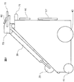
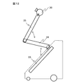
- FIG. 1 The perspective view which shows the whole structure of the mobile X-ray imaging apparatus of 1st embodiment.
- Side view of the mobile X-ray imaging apparatus of FIG. 1 is a front view of the mobile X-ray imaging apparatus of FIG.
- Rear view of the mobile X-ray imaging apparatus of FIG. The figure explaining the structure of the X-ray tube part of 1st embodiment
- steering-wheel of the mobile X-ray imaging apparatus of 1st embodiment (a) is a top view, (b) is a side view of a handle.
- steering-wheel of the mobile X-ray imaging apparatus of 1st embodiment (a) is a top view
- (b) is a side view of a handle.
- FIG. 1A illustrates a state in which the support frame is housed in the main body
- Side view showing an example of the posture of the mobile X-ray imaging apparatus of FIG.
- the rear view which shows the other example of the attitude
- Functional block diagram of the control device of the mobile X-ray imaging apparatus of the second embodiment (A), (b) is a figure explaining the movable range of the arm part in 2nd embodiment, respectively.
- the figure explaining the balancer of the mobile X-ray imaging apparatus of 3rd embodiment The figure explaining the balancer of the mobile X-ray imaging apparatus of 3rd embodiment
- the mobile X-ray imaging apparatus includes an X-ray tube unit, a main body that houses a drive device for the X-ray tube unit, wheels provided on the main body, and an arm that connects the X-ray tube unit and the main body.
- the arm unit has a plurality of foldable arms.
- the main body has a storage recess for storing the folded arm portion inside the main body surface.
- the arm part has one end slidably supported by the storage recess, and one end part slidably connected to the main body,
- An X-ray tube portion is fixed to one end portion and has a second arm that can be folded with respect to the first arm.
- the other end portion of the second arm is connected to the other end portion of the first arm so as to be rotatable about the longitudinal axis of the second arm.
- the main body of the mobile X-ray imaging apparatus of the present embodiment has an inclined surface on the front surface in the traveling direction, and a storage recess on the inclined surface.
- the inclined surface is a flat surface or a curved surface that is convex upward.
- the arm constituting the arm portion can have a curved shape along the curved surface of the inclined surface.
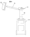
- FIG. 1 is a perspective view seen from the front side of the X-ray imaging apparatus
- FIGS. 2 to 4 are a side view, a front view, and a rear view, respectively.
- the left-right direction in FIG. 2 (side view) is referred to as the front-rear direction of the apparatus
- the left-right direction in FIG. 3 is referred to as the left-right direction of the apparatus.
- the X-ray imaging apparatus of the present embodiment has a main body 10 having a substantially triangular side surface, an arm portion 30 fixed to the main body 10, and fixed to one end of the arm portion 30.
- the X-ray tube unit 20 and a carriage unit are included.
- a power supply device for driving the carriage unit a power supply device or charging device for driving the X-ray tube unit 20, driving of the X-ray tube, and
- a control device for controlling the operation of each mechanism provided in the X-ray imaging apparatus, a balancer for controlling the position of the center of gravity of the X-ray imaging apparatus, and the like are housed.
- the bottom part of the main body 10 is fixed to a carriage part provided with wheels (front wheels 41 and rear wheels 42).
- the wheel can be fixed to the main body 10 (cart unit) via a damper, a spring, or the like.
- the front wheel 41 is a universal wheel for changing the direction of the apparatus
- the rear wheel 42 is a driving wheel driven by a driving source and has a larger diameter than the front wheel 41.
- the rear wheel 42 may be inclined with respect to the vertical surface. In this case, the distance between the two rear wheels is the largest at the portion in contact with the floor surface. As a result, even when the heavy X-ray tube portion 20 positioned in front of the rear wheel is moved with respect to the main body 10, the main body 10 can be prevented from coming into close contact with the floor surface and becoming unstable in posture. .
- the rear wheel 42 which is a drive wheel is provided with an electromagnetic lock or the like for locking / releasing the drive, and can run only when the lock is released.
- the housing of the main body 10 has a front panel 10A located on the front side of the apparatus, two side panels 10B having a substantially triangular shape, and a back panel 10C located on the rear side.
- the front panel 10 that connects the two side panels 10B has a surface that is inclined with respect to the vertical surface, corresponding to the triangular shape of the side panel 10B.
- a storage recess 11 for storing a part or all of the arm portion 30 is formed inside the panel surface.
- One end of the arm portion 30 is pivotally supported in the storage recess 11, and is rotated from the support shaft (not shown) as a center to be stored in the storage recess 11 (FIG. 2). It is possible to move to the drawn state shown in FIG.
- the storage recess 11 is provided with a slide mechanism for moving one end of the arm portion 30 pivotally supported by the storage recess 11 along the longitudinal direction of the storage recess 11. By this sliding mechanism, the arm portion 30 moves from the lower end position of the storage recess 11 shown in FIGS. 1 and 2 to the upper end position. Details of the arm unit 30 and its support mechanism will be described later.
- An X-ray tube storage portion 13 for storing the X-ray tube portion 20 fixed to the arm portion 30 is formed on the front panel 10A continuously from the lower end of the storage recess 11. As shown in FIG. 3, the X-ray tube portion 20 fixed to one end of the arm portion 30 is in a state where the arm portion 30 is housed in the housing recess 11 and the X-ray irradiation window side (aperture portion) is stored in the X-ray tube. It is stored in the X-ray tube storage part 13 so as to face the bottom of the part 13.
- a support frame 50 that supports a portable X-ray detector (not shown) is further attached to the front panel 10 ⁇ / b> A, and a groove portion that stores the support frame 50 includes an X-ray tube storage portion 13 and a storage recess 11. It is provided on both sides.
- the X-ray detector is a known X-ray detector such as an FPD (Flat Panel Detector), and imaging is performed in a state where the X-ray detector is positioned so as to face the X-ray tube unit 20 with the subject interposed therebetween. Therefore, although the position (posture) of the X-ray detector varies depending on the relationship with the X-ray tube unit 20, the support frame 50 can function as a support that fixes one posture of the X-ray detector. Details of the support frame 50 will be described later.
- the rear panel 10 ⁇ / b> C of the main body 10 is provided with an X-ray detector storage unit 17 for storing a portable X-ray detector.
- the shape of the X-ray detector accommodating portion 17 may be any structure that can stably support the X-ray detector, and the shape is arbitrary such as a frame shape or a pocket shape.
- the X-ray detector storage unit 17 can further include a terminal unit for connecting the X-ray detector to a power supply device or an image forming apparatus installed in the main body.
- a terminal unit for connecting the X-ray detector to a power supply device or an image forming apparatus installed in the main body.
- the X-ray detector storage unit 17 includes such a terminal unit, for example, when an X-ray detector that has been imaged is stored in the X-ray detector storage unit 17, The terminal portion of the line detector is connected, and the X-ray detector can be charged, or a signal detected by the X-ray detector can be read by the image forming apparatus to create and display an image.
- the X-ray detector storage unit 17 may include a sterilizing ultraviolet ray generation source and the like, and the ultraviolet ray generation source is configured to operate when the X-ray detector is stored in the storage unit 17.
- the X-ray detector can be sterilized by ultraviolet irradiation for each imaging.
- a display panel 61 for displaying a GUI for inputting to the control device and the above-described image and the like is installed on the upper portion of the X-ray detector storage unit 17.
- an operation panel on which operation buttons and the like are arranged may be installed.
- the display panel 61 may be fixed to the main body 10 or may be removable.
- a moving handle 71 (hereinafter also simply referred to as a handle 71) for moving the X-ray imaging apparatus is fixed to the upper end of the rear panel 10C. An operator can stand on the back side of the X-ray imaging apparatus and press the handle 71 to move the X-ray imaging apparatus to a desired location.
- the moving handle 71 is provided with a deadman switch. When the handle 71 is grasped, this switch is pushed down, the lock of the carriage (rear wheel 42) is released, and the carriage can be moved freely in the state where the switch is pushed down. Further, when the switch is released, the rear wheel 42 is locked.
- the X-ray tube unit 20 is a part including an X-ray tube and devices and mechanisms attached thereto.
- the X-ray tube unit 20 is an integrated type in which a cylindrical X-ray tube and a high voltage generator are housed in an integrated case. And an X-ray movable diaphragm fixed to the X-ray irradiation window side.
- an infrared rangefinder for determining the position with the X-ray detector may be fixed to the movable diaphragm.
- the high voltage generator is connected to a power supply device housed in the main body 10 via a cable (not shown). The cable is drawn into the main body 10 through the arm portion 30.
- the X-ray tube unit 20 is fixed to the tip of the arm unit 30 by a cage 21 fixed to both ends of the cylindrical cover.
- a cage 21 fixed to both ends of the cylindrical cover.
- the X-ray irradiation side can be directed in an arbitrary direction.
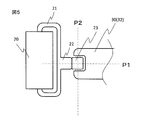
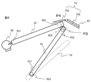
- FIG. 5 An example of a connecting portion between the cage 21 and the arm portion 30 of the X-ray tube portion 20 is shown in FIG.
- the cage 21 has a first shaft portion 22 at the center thereof, and the first shaft portion 22 is attached to a second shaft portion 23 that is pivotally supported at the tip of the arm portion 30. It is pivotally supported.
- the first shaft portion 22 rotates about the axis P1 with respect to the second shaft portion 23, and the second shaft portion 23 rotates about the axis P2 orthogonal to the axis P1 with respect to the arm portion 30. .
- the X-ray irradiation window is directed from the lower side to the side (left or right) side and further upward. It can be changed to the state it was in. Furthermore, by rotating the X-ray tube portion 20 around the axis P1 in these states, the angle of the diaphragm device can be changed. In addition to these two directions of rotation, rotation of the X-ray tube portion 20 with respect to the shaft portion 22, that is, a neck swinging operation can be added.
- Rotation of the X-ray tube unit 20 around the axes P1 and P2 is limited to less than 360 degrees to prevent the cable connected to the X-ray tube unit 20 from being threaded.
- the connecting portion between the cage 21 and the arm portion 30 of the X-ray tube portion 20 is not limited to that shown in FIG. 5, and the shaft of the cage 21 is pivotally supported by the arm portion 30 as shown in FIG. 1.
- the structure can also be adopted.
- the above-described rotation and neck motion of the X-ray tube unit 20 may be performed manually or by power of a small motor or the like. Further, the mechanism for limiting the rotation angle may be a mechanical mechanism or an electrical mechanism. When the X-ray tube unit 20 is driven by electric power, an operation button for operating the X-ray tube unit 20 is provided on an arm operation handle described later, or the X-ray tube unit 20 is driven by a control device. It can also be performed automatically.
- the X-ray tube unit 20 may be provided with a handle (not shown) for manual operation.
- the arm unit 30 includes two arms, that is, a first arm 31 fixed to the main body 10 side and a second arm to which the X-ray tube unit 20 is fixed.
- the first arm 31 is connected to the main body 10 in a foldable (rotatable) manner
- the second arm 32 is connected to the first arm 31 in a foldable (openable and closable) manner.
- a rotation shaft of the first arm 31 is fixed to an end 311 of the first arm 31 connected to the main body 10, and the rotation shaft is moved in the longitudinal direction of the storage recess 11 in the storage recess 11 of the main body 10.
- a slide mechanism is provided for this purpose.
- the slide mechanism a known mechanism can be adopted.
- an elongated groove or an opening (guide portion) formed along the longitudinal direction is formed on the bottom surface or side surface of the storage recess 11 and the first arm is formed.
- Wheels 313 are provided at both ends of a rotating shaft fixed to the end portion 311 of the wheel 31, and the wheels 313 engage with the groove and slide in the groove.
- the slide mechanism As the slide mechanism, a combination of a groove and a wheel, a combination of a rail and a wheel, a rack and a pinion, and the like may be adopted. Thereby, the end 311 of the first arm 31 can move from the lower end to the upper end of the storage recess.
- an elongated opening (guide portion) 12 provided on the side surface of the storage recess 11 is indicated by a dotted line.
- the wheel 313 provided on the end side of the first arm 31 that engages with the opening 12 is fixed to a shaft that penetrates the end 311 in a direction orthogonal to the longitudinal direction of the first arm 31.
- the 1st arm 31 can rotate centering on the axis
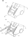
- the second arm 32 is fixed to the end 312 opposite to the end 311 fixed to the main body 10 of the first arm 31 so as to be openable and closable and rotatable.
- the end 322 of the second arm 32 is connected to the end 312 of the first arm 31 via a shaft 323.
- the shaft portion 323 is supported on the end portion 312 of the first arm 31 by the shaft P3 and can rotate around the shaft P3.
- the end 322 of the second arm 32 is supported by a shaft P4 with respect to the shaft 323, and can rotate (turn) around the shaft P4.
- the mechanism shown in FIG. 6 is an example for achieving the above-described movement of the second arm 32 with respect to the first arm 31, and conversely, the shaft portion 323 rotates around the axis P4 with respect to the first arm.
- the second arm 32 may be configured to rotate about the axis P3 with respect to the shaft portion 323, or another joint mechanism may be employed.
- the above-described slide and rotation of the first arm 31 (change of the opening angle) and rotation around the axes P3 and P4 of the second arm 32 (change of the opening angle and the turning angle) use an arm operation handle described later. It is also possible to perform the operation manually, or an electric drive source (not shown) such as a motor can be used supplementarily. By using the drive source, the arm unit 30 on which the heavy X-ray tube unit 20 is mounted can be easily moved by a handle or an operation tool, and the operation of the arm unit 30 can be semi-automated. .
- the arm portion 30 is attached to the slide mechanism and rotation mechanism of the first arm 31 and the rotation mechanism of the second arm 32 to lock the first and second arms 31 and 32 at a predetermined slide position and rotation position.
- a mechanism (not shown) for releasing is provided.
- the lock mechanism is a mechanism that mechanically or electrically locks the slide and rotation of the first and second arms 31 and 32.
- an electromagnetic lock or the like can be adopted, and the lock and unlock can be performed by operating a pedal, lever, or button. It can be performed.
- the arm unit 30 includes a position detector such as an encoder in order to detect the position, opening angle, and turning angle of the first and second arms 31 and 32 in the sliding direction.
- a position detector such as an encoder
- the detection results of the positions and angles of the first and second arms 31 and 32 detected by the position detector can be used for controlling the arm unit 30.
- the arm operation handle 72 (hereinafter also simply referred to as handle 72) for the operator to operate the arm unit 30 will be described.
- the arm operation handle 72 is provided at a connection portion between the first arm 31 and the second arm 32.
- the connection portion is provided with a cover 73 that covers the connection portion, and the handle 72 is fixed to the cover 73.
- the operation handle 72 is a handle provided with deadman type switches 75 and 76 that hold the operation while being pushed down, and the switches 75 and 75 are pushed down by the operation of grasping the handle 72. Then, a lock mechanism that locks the positions of the first arm and the second arm, for example, an electromagnetic lock is released, and the movement becomes possible. With respect to the slide position, for example, the lock is released only when both the switches 75 and 76 are pressed down. Alternatively, a switch for locking / releasing the slide position may be provided separately from the switches 75 and 76.
- the end 312 of the first arm 31 can be lifted to change the angle (opening angle) with respect to the main body 10.
- the end 311 of the first arm 31 can be slid and moved above the storage recess 11.
- the upward sliding of the first arm 31 may be interlocked with the opening angle.
- the opening angle is increased as the first arm 31 slides upward, and the first arm 31 is moved into the storage recess 11. In a state where the upper arm is moved to the upper end, the first arm 31 is made substantially vertical.
- the slide mechanism After lifting the first arm 31 to a predetermined slide position, the slide mechanism is locked and the opening angle of the first arm 31 and the second arm 32 is adjusted.
- the switches 75 and 76 are not operated, the first arm 31 and the second arm 32 are both locked and do not move. However, for example, when the switch 76 is pushed down while holding the handle 72, the lock of the first arm 32 is released. Is done. In this state, when the operator pushes down or pushes up the handle 72, the second arm 32 rotates about the axis P3, and as a result, the end 321 to which the X-ray tube unit 20 is fixed rises or falls, The position of the X-ray tube unit 20 can be changed. By stopping the pressing operation of the switch 76, the second arm 32 is fixed at that position.
- the second arm 32 can be rotated or turned around the axis P4. .
- the X-ray tube part 20 can be rotated in the left-right direction.
- the above-described operation of the arm unit 30 is an example and does not limit this embodiment.
- the slide and rotation of the first arm 31 and the rotation of the second arm are respectively performed by an electric drive device, the operation of lifting the operation handle 72, the operation of lifting, or the operation of rotating the operation handle 72 described above operates the drive device.
- the control signal is transmitted.
- the handle 72 may be provided with operation buttons 77 and 78 for rotating the X-ray tube unit 20 as shown in FIG.
- operation buttons 77 and 78 for rotating the X-ray tube section 20 shown in FIG. 5 around the axis P1 and rotating around the axis P2 are provided, respectively. It is provided at a position where it can be easily operated with the thumb of the gripped hand, for example, on the outer surface of the handle 72. Accordingly, the X-ray tube unit 20 can be rotated and swung even at a position away from the X-ray tube unit 20 and set at a position facing the X-ray detector.
- a cover 73 covering the connecting portion of the first arm 31 and the second arm 32 is fixed (axially supported) to the end 322 of the second arm 32, and the end of the handle 72 described above is integrally formed on the side surface thereof. It is fixed.
- the shape of the cover 73 is not particularly limited, in the illustrated embodiment, the two top panels 73A and 73B (FIG. 6) are connected with an obtuse angle, and thin side panels are formed on both sides of the plate material. It has a joined shape. In FIG. 6, the side panel is omitted and only the top panels 73A and 73B are schematically shown.
- the cover 73 can keep the top panel 73A substantially horizontal even when the first arm 31 rotates.
- a second display panel 62 is provided on the top panel 73B located on the handle 72 side, separately from the display panel 61 (first display panel). .
- the second display panel 62 may have a display function different from that of the first display panel 61 fixed to the back surface of the main body 10, or may function as a display device that supplements the display panel 61. May be. For example, a GUI dedicated for operation or a display panel for images may be displayed, or both may be displayed.
- the display panel 62 may be fixed to the cover 73 or may be detachable from the cover 73. As described above, since the upper panel 73A, 73B is connected to the cover 73 with an angle, the display panel 62 can have an angle with respect to the horizontal plane, and the operator can easily view the screen.
- the support frame 50 is composed of a pair of parallel rod-shaped members, and each rod-shaped member has a structure in which two members (a support member 51 and a link member 52) are connected. 52 is inserted into the main body 10 through two openings 19 provided in the main body 10, and is supported in the main body 10 so as to be movable in the vertical direction and rotatable by a support portion (not shown).
- the opening 19 is formed in an elongated shape along both sides of the X-ray tube storage portion 13 formed in the front panel 10 ⁇ / b> A, and is supported below the front panel 10 ⁇ / b> A continuously to the opening 19.
- a groove portion 15 for accommodating the frame 50 is formed.
- the groove 15 is composed of two grooves in the vertical direction parallel to each other.
- the support frame 50 (rod-like member) is folded and stored in the groove portion 15, the support frame 50 is substantially in the same plane as the panel surface of the front panel 10A. It will fit.
- the support frame 50 is configured by two rod-shaped members, the arm unit 30 is folded from above the arm frame 30 and the X-ray tube unit 20 in a state where the support frame 50 is housed in the front panel 10A. Even when stored in the storage recess 11 and the storage unit 13, both can be stored in each storage unit without the X-ray tube unit 20 and the support frame 50 colliding with each other.
- the height of the support frame 50 can be adjusted by moving the link member 52 up and down along the opening 19. This makes it possible to adjust the distance between the X-ray detector set on the support member 51 and the X-ray tube unit 20 disposed opposite to the X-ray detector with the subject interposed therebetween. Note that the distance between the X-ray detector and the X-ray tube unit 20 is adjusted using this rangefinder when the X-ray tube unit 20 includes a rangefinder.
- the support frame 50 made of a rod-shaped member, but the shape of the support frame 50 is not limited to a rod shape as long as it does not interfere with the movement of the arm portion 30 and the X-ray tube portion 20, and is an H-shape. It can be arbitrarily changed.
- FIGS. 1-10 An example is shown in FIGS.
- FIG. 9 shows a state where the first arm 31 is moved to the uppermost end in the sliding direction and the opening angle thereof is maximized, and the second arm 32 is opened so that the longitudinal direction thereof is substantially horizontal.
- the X-ray tube portion 20 is positioned substantially opposite the X-ray detector. Imaging is performed by placing the subject in an arbitrary posture between the X-ray tube unit 20 and the X-ray detector and adjusting the position of the X-ray tube unit 20 so that the X-ray irradiation position coincides with the X-ray detector. Is possible.
- FIG. 10 shows a state in which the second arm 32 is turned about 90 degrees with respect to the first arm 31 from the state shown in FIG. 9, and the X-ray tube unit 20 is further rotated so that the X-ray irradiation window faces sideways. It is.
- the subject can stand up so as to face the X-ray tube unit 20 or can be photographed while sitting on a chair.
- the height of the X-ray tube unit 20 can be adjusted by adjusting the sliding position and opening angle of the first arm 31, the opening angle of the second arm 32, and the like.
- the structure and shape of the X-ray imaging apparatus according to the present embodiment have been mainly described, but the main effects brought about by these structures are exemplified.
- the X-ray imaging apparatus supports the X-ray tube with a foldable arm portion instead of a support column, and has a structure in which the arm portion can be housed in the front panel of the main body housing.
- the X-ray imaging apparatus can be moved without obstructing the view of the operator who operates standing up.
- the front panel is inclined from the back to the front, the field of view can be opened to the front of the apparatus, and the front end of the apparatus can be prevented from colliding with an object or a person.
- the shape of the inclined surface is an upwardly convex curved surface, it is possible to increase the storage volume of the main body housing while ensuring a view from the back to the front.
- the X-ray imaging apparatus includes a mechanism for sliding the end of the arm connected to the main body housing within the storage recess, thereby increasing the movable range of the arm. Even in a hospital room or the like where the apparatus installation space is limited, the arm portion can be expanded and contracted from a different height to a desired position, thereby enabling photographing in various postures.
- the X-ray imaging apparatus of the present embodiment can protect the X-ray tube when the apparatus is moved or stored by providing an X-ray tube storage part continuously with the storage recess for storing the arm part. .
- the X-ray imaging apparatus of the present embodiment is provided with a handle for operating the arm part at the connecting part of the two arms constituting the arm part, so that the X-ray tube part can be operated even when the X-ray tube part is at a high position.
- the X-ray tube can be moved through the arm portion without forcing the person into an unreasonable posture.
- it is difficult for a short operator to operate an X-ray tube at a high position but this problem is solved.
- the X-ray tube at a low position can be lifted or rotated by the handle while standing.
- the operability is further improved by providing a switch for operating the rotation of the X-ray tube with respect to the arm portion on the arm operation handle.
- the X-ray imaging apparatus of the present embodiment is in a stable state in which the X-ray detector is fixed using the support frame by attaching a support frame for mounting the X-ray detector to the front panel. You can shoot with it. Further, by fixing the support frame to the main body so as to be movable up and down, the X-ray detector can be moved up and down and the distance from the X-ray tube portion can be adjusted to match the height of the subject.
- the X-ray tube portion 20 is positioned above the storage recess 11, so that the storage portion 13 for storing the X-ray tube portion 2 is continuously above the storage recess 11. It is preferable to provide them.
- the structure and movement of the arm part 30 are the same as in the first embodiment.
- the X-ray tube part 20 when the apparatus is moved, that is, when the arm part is housed, the X-ray tube part 20 is positioned above the apparatus, so that collision between the X-ray tube part and an object or a person can be avoided more reliably.
- the X-ray tube portion is preferably provided with a protective cover because the diaphragm device is in a posture facing upward.
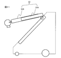
- Fig. 11 shows an example in which a telescopic mechanism is added to the second arm.
- the second arm 32 includes an inner arm 32 ⁇ / b> A to which the X-ray tube unit 20 is fixed and an outer arm 32 ⁇ / b> B connected to the first arm 31.
- the outer arm 32B has a space for receiving the inner arm 32A therein, and the inner arm 32A is fitted into this space and is slidably inserted along the longitudinal direction.
- the end of the inner arm inserted into the outer arm and the end of the outer arm have a structure that engages with each other, and the inner arm 32A does not come off the outer arm 32B.
- the inner arm 32A is driven by, for example, a driving device provided inside the outer arm 32B, such as a hydraulic cylinder, and can slide in the outer arm 32B.
- the movable range of the X-ray tube unit 20 limited by the length of the arm can be increased without increasing the length of the arm unit 30 in the folded state. Can be spread. That is, when the X-ray imaging apparatus is moved, it is possible to take an image at a position further away from the main body while ensuring a wide front field of view.
- FIG. 12 shows an example in which the arm portion is composed of three arms.
- the arm portion includes a first arm 33, a second arm 34, and a third arm 35, and an end portion of the first arm 33 is slidably fixed to a storage recess formed in the main body 10, and The X-ray tube portion 20 is fixed to the end portions of the three arms 35.
- the end portion of the first arm 33 and the end portion of the second arm 34 are shaft portions that enable rotation in two orthogonal directions, like the connecting portion of the first arm and the second arm in the first embodiment, respectively. Are connected by
- the arm portion of the X-ray imaging apparatus of this modification has the three arms 33 to 35 in a state of being substantially parallel to each other with the folding angle at each connecting portion minimized, and a storage recess provided on the front panel of the main body. In addition, a part or all of them are stored.
- the posture shown in FIG. 9 and FIG. 10 can be taken by appropriately changing the inter-arm angle and the arm turning angle of each connecting portion of the arms 33 to 35.
- the X-ray tube can be positioned at an arbitrary position.
- the X-ray tube portion is positioned above the storage recess with the arm portion stored in the storage recess, the X-ray tube portion and the object or person can be more reliably collided. Can be avoided.
- the structure of the X-ray imaging apparatus has been mainly described.
- the present embodiment is characterized in that the control device of the X-ray imaging apparatus has a function of controlling a mechanism constituting the X-ray imaging apparatus. It is.
- the mobile X-ray imaging apparatus of this embodiment further includes a control device that controls the movement of the arm unit.
- the mobile X-ray imaging apparatus of the present embodiment further includes a detection unit that detects the position of the X-ray tube, and the control device controls the operation of the arm unit based on the position of the X-ray tube detected by the detection unit. Control.
- the movable range is limited for each mechanism.
- each mechanism is movable. Even if the range is moved or rotated, there is a possibility of taking an inappropriate position as the X-ray tube unit 20 depending on the combination, for example, a position that interferes with the main body casing or a position that impairs the center of gravity balance of the apparatus.
- the mechanism is controlled so as not to exceed a predetermined movable range of the X-ray tube unit 20 by the control device, thereby restricting the X-ray tube unit 20 from moving to the inappropriate position described above. .
- the structure of the X-ray imaging apparatus of the present embodiment is the same as that of the above-described embodiment, and thus the description thereof will be omitted.
- the function of the control apparatus will be mainly described.
- the drawings and symbols used in the description of the first embodiment will be referred to as appropriate.
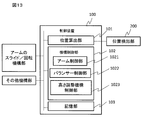
- Fig. 13 shows a functional block diagram of the control device.
- the control device 100 has, as main functions, a position calculation unit 101 that calculates the position of the X-ray tube unit 20, and a mechanism control that controls the mechanism unit based on the position information of the X-ray tube unit 20 calculated by the position calculation unit 101. And a storage unit 103 for storing data necessary for control.
- the control device controls the start and end of imaging such as X-ray irradiation from the X-ray tube in addition to the functions shown in FIG. 13, but description of control related to imaging is omitted here.
- Each unit included in the mechanism control unit 102 corresponds to a mechanism included in the X-ray imaging apparatus.
- FIG. 13 shows the arm control unit 1021, the balancer control unit 1023, and the height adjustment mechanism control unit 1025, some of these can be omitted or added depending on the structure of the apparatus. In the present embodiment, a case where the arm control unit 1021 is provided will be described.
- the arm mechanism controlled by the arm control unit 1021 includes a mechanism for sliding the first arm, a mechanism for rotating, a mechanism for rotating the second arm, a mechanism for rotating, and the like, and a mechanism for expanding and contracting the arm is added. In some cases, a telescopic mechanism is also included.
- the arm control unit 1021 also controls mechanisms of the X-ray tube unit 20 such as a mechanism that rotates the X-ray tube in two directions (two rotation mechanisms) and a mechanism that swings the neck.
- the position calculation unit 101 obtains position information of the X-ray tube unit 20 from the position detector 200.
- the position detector 200 may be a position detector that directly detects the position of the X-ray tube unit 20 using infrared rays or magnetism, or detects the slide position or rotation angle of the slide mechanism or the rotation mechanism of the arm unit 30.
- a position detector may be used. These rotation angles and the like can be detected by providing a sensor (position detector) for detecting the rotation amount of an encoder or the like in each rotation mechanism unit. Further, when a drive source that electrically drives rotation is provided, information on the rotation amount can be obtained from the drive amount of the drive source.
- the position information of the X-ray tube unit 20 is obtained from the rotation angles of the arms 31 and 32 constituting the arm unit 30 of the X-ray tube unit 20. That is, since the lengths of the first arm 31 and the second arm 32 and the distance from the end 321 of the second arm 32 to the X-ray tube unit 20 are constant, as shown in FIGS.
- the position of the end 312 of the first arm 31 can be determined from the position (s) in the sliding direction of the storage recess 11 of the end 311 of 31 and the rotation angle ( ⁇ ) of the first arm 31.
- the positions of the end 321 of the second arm 32 and the X-ray tube unit 20 can be specified from the angle ( ⁇ ) and the turning angle ( ⁇ ).
- a movable range R (an inner range surrounded by a dotted line) of the X-ray tube unit 20 as shown in FIG. 15 is stored as position coordinates with a predetermined position of the apparatus as an origin.
- FIG. 15 shows the movable range R in a plan view, but actually there is a limitation on the movable range also in the height direction.
- the movable range is a three-dimensional range such as a cylinder having a predetermined height with a cross section of a substantially oval shape shown in FIG. 15 and a rotating body obtained by rotating a substantially oval shape around a longitudinal axis.
- the portion of the main body 10 is excluded from the movable range R.
- the movable angle range of the first arm and the movable angle range of the second arm at each position are determined for each position of the first arm 31 in the sliding direction. It may be stored.
- the mechanism control unit 102 (arm control unit 1021) drives the arm unit 30 based on the position of the X-ray tube unit 20 calculated by the position calculation unit 101 and the position information of the ends of the arms 31 and 32. A signal is sent to each unit, and the operation of each mechanism unit is restricted so that each mechanism unit does not move the X-ray tube unit 20 beyond the range stored in the storage unit 103. Alternatively, the mechanism is locked so that the mechanism does not move beyond the movable range by operating the lock mechanism.
- FIG. 16 shows an example of the control procedure of the control device 100.
- a description will be given assuming that when one of the plurality of mechanism portions that move and rotate the arm portion is movable, the other mechanisms are locked.
- the control device 100 is based on information from the position detector.
- the position of the part is calculated (S502). It is determined whether or not the calculated position of the X-ray tube portion is within the movable range (S503). If it is within the range, monitoring of the position of the X-ray tube is continued.
- the mechanism part N which has been unlocked, is brought into a locked state (S504).
- the mechanism portions other than the mechanism portion N are unlocked (S501), and the above-described steps S502 to S504 are repeated.
- the movement of the X-ray tube is set at a predetermined position, the operation for controlling the mechanical unit is finished and imaging is performed.
- the X-ray tube portion 20 does not become lower than the predetermined level H and the front surface of the main body 10
- the angle ⁇ of the first arm 31 and the angle ⁇ of the second arm are regulated so as not to be longer than the distance D.
- each mechanism unit is controlled by the control device based on a preset movable range of the X-ray tube unit, thereby moving a plurality of independently movable mechanisms to perform X-rays.
- the position of the tube part 20 it is possible to prevent the X-ray tube part 20 from inadvertently colliding with the main body 10 or being moved to a position where the balance of the apparatus is lost.
- the position detector for detecting the position of the X-ray detector detects the position. It is also possible to control each mechanism unit so as to move the X-ray tube unit 20 to a position facing the X-ray detector using the position information of the X-ray detector.
- a position detector for detecting the position of the X-ray detector there is an X-ray detector having a built-in transmitter, and a receiving device for specifying the position of the X-ray detector by receiving a signal from the transmitter; A position detector using magnetism or infrared light can be employed.
- a balance mechanism for balancing the X-ray imaging apparatus as the X-ray tube moves.
- the balance mechanism includes a weight (balancer) and a mechanism that slides the weight in the horizontal direction, a mechanism that changes the inclination of the wheel with respect to the vertical plane, a mechanism that changes the inclination of the main body, and the like. Good.
- the heavy element such as the power supply device is arranged in the main body 10, so that even when the relatively heavy X-ray tube portion 20 is located outside the main body 10.
- the center of gravity is maintained in the main body 10 to prevent the posture from becoming unstable.
- the length of the arm needs to be a predetermined length in order to ensure the degree of freedom of the imaging position. If it is far away from the main body 10, the posture of the apparatus becomes unstable and may fall down.
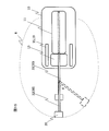
- the X-ray imaging apparatus stabilizes the posture by arranging a balancer that moves as the X-ray tube moves.
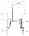
- the balancer 80 is installed behind the bottom of the main body 10 on a guide rail 81 that moves the balancer 80 in the front-rear direction and the left-right direction.
- a weight made of a material having a large specific gravity is used.
- movable elements can be used as part or all of the balancer.
- the guide rail 81 may be, for example, a combination of a Y rail that moves the balancer 80 in the front-rear direction and an X rail that moves the Y rail in the left-right direction.
- the X rail is fixed in the main body 10 and defines the range of movement of the balancer 80 in the left-right direction.
- a guide for moving the Y rail along the X rail is fixed to the X rail, and the Y rail is movable in the Y direction with respect to the guide.
- the balancer 80 is fixed to the Y rail and moves together with the Y rail. In the present embodiment, the balancer 80 can move to a position that partially protrudes from the main body 10 in the Y direction.
- the rear panel 10 ⁇ / b> C of the main body 10 is provided with an opening 18 for entering and exiting the balancer 80. Needless to say, if the storage volume of the main body 10 is sufficient, the balancer may be moved back and forth within the main body 10.
- the movement of the balancer 80 along the guide rail 81 can be performed by a driving source such as a motor.
- the drive source can be incorporated in the balancer 80 itself, operates under the control of the control device 100 (FIG. 13), and moves the balancer 80 in a predetermined direction along the guide rail 81.
- the balancer 80 does not move when the position of the X-ray tube unit 20 is within a predetermined range with respect to the main body 10, but the balancer 80 moves when the position exceeds the predetermined range.
- the predetermined range is, for example, a range where the center of gravity of the apparatus is within the main body 10.
- the position of the X-ray tube unit 20 is acquired from a position detector that detects the position of the X-ray tube unit 20.
- the position of the end 311 along the slide mechanism of the first arm 31 and the first arm rotation angle ( ⁇ ), the rotation angle ( ⁇ ) of the second arm 32 with respect to the first arm, and the turning angle ( ⁇ ) are X-rays.
- the position of the pipe part 20 may be calculated. These angles can be known from the operation amount of the rotation mechanism.
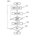
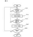
- FIG. 5 An example of the control procedure of the control device 100 is shown in FIG.
- the control device 100 calculates the position of the X-ray tube unit 20 from the rotation angle of each arm constituting the arm unit 30 described above. (S512). It is determined whether or not this position is within the allowable range (S513). If the position exceeds the allowable range, a signal is sent to a drive source (not shown) of the balancer 80, and the direction in which the X-ray tube unit 20 exceeds the allowable range. The balancer 80 is moved to the opposite side (S514).
- the amount of movement of the balancer 80 is determined by the relationship with the amount of movement of the X-ray tube unit 20 depending on the weight of elements constituting the X-ray imaging apparatus including the X-ray tube unit 20 and the balancer 80, and should be obtained in advance by simulation or the like. Can do. This operation is repeated when imaging is performed by changing the position of the X-ray tube unit 20 (S515).
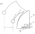
- FIG. 17 shows a case where the balancer 80 is moved backward when the X-ray tube unit 20 exceeds the allowable range in the front.
- the front allowable movable range is indicated by a thick dashed line.
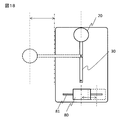
- FIG. 18 shows a case where the balancer 80 is moved in the right direction when the X-ray tube unit 20 has turned and the allowable range in the left direction in the figure is exceeded.
- the allowable movable range is a range in the left and right end portions of the main body 10, and representatively, only the left end is indicated by a thick one-dot chain line. The same applies when the center of gravity moves to the right, and the balancer 80 moves to the left.
- the X-ray tube portion 20 is not planned to be positioned rearward beyond the back panel 10C of the main body 10, but the X-ray tube portion 20 is moved rearward depending on the configuration of the connecting portion of the arm portion. It may be moved. In that case, it is possible to adopt a configuration in which the balancer 80 is moved forward, or a second balancer is arranged in front of the power supply device.
- 17 and 18 show a state in which the X-ray tube unit 20 is moving forward or in the left-right direction.
- the movement of the center of gravity associated with downsizing the apparatus can be mitigated, and the posture can be kept stable.
- the balancer is used to stabilize the posture of the X-ray imaging apparatus.
- the present embodiment is characterized in that the posture of the apparatus itself is varied to stabilize the posture.
- the posture is stabilized regardless of the movement of the X-ray tube unit 20.
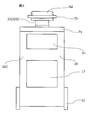
- FIG. 20 shows an example of the height adjustment mechanism 85 provided on the rear wheel 42.
- the height adjusting mechanism 85 of this example is a known mechanism that generates a force in a linear direction, such as a hydraulic cylinder, for example, and the carriage portion of the main body 10 is set so that the moving direction of the piston that is the moving element is horizontal. 40 is fixed.
- Both ends of the rear wheel 42 are supported by shaft support portions 421 so that the rotation axis thereof is parallel to the horizontal direction or has a predetermined angle with respect to the horizontal direction.
- the shaft support portion 421 has a U-shaped cross section, supports a wheel that sandwiches the wheel at two ends, and the end opposite to the two ends is connected to the piston portion of the height adjustment mechanism 85. Has been.
- the rear wheel 42 When a force in the left-right direction toward the center of the main body is applied to the upper end portion of the shaft support portion 421 by the height adjusting mechanism 85, the rear wheel 42 is inclined with the installation surface of the floor moving outward, and the floor surface and the main body The distance to 10 changes. That is, the height of the device is lowered (change from H1 to H2). As shown in the drawing, if the lateral force applied to both rear wheels 42 is equal, the rear side of the apparatus as a whole becomes lower. When a lateral force is applied to only one of the left and right rear wheels 42, only the other wheel is tilted while the other wheel 42 is in substantially the same state. As a result, the device is tilted to the left or right. Become.
- the height adjustment mechanism 85 is not limited to the mechanism shown in FIG. 20 as long as it changes the height of the main body, and may be a mechanism that rotates the shaft support portion 421 so that the rear wheel 42 tilts, for example. It may be a mechanism for changing the height of the main body relative to the wheel by moving the wheel shaft support portion 421 in a direction perpendicular to the main body.
- the driving of the height adjusting mechanism 85 of the present embodiment can also be controlled by the control device 100 based on the position information of the X-ray tube unit 20 in the same manner as the driving of the balancer in the third embodiment. That is, for example, when the X-ray tube portion 20 moves to the right side in the left-right direction of the main body 10 and the center of gravity cannot be maintained in the main body 10, the inclination of the left rear wheel 42 is increased so that the left side of the main body 10 is lowered. Tilt. As a result, the position of the center of gravity moves to the left and can be maintained in the main body 10. When the X-ray tube unit 20 moves to the left, the inclination of the right rear wheel is increased.
- a mobile X-ray imaging apparatus that has good operability at the time of movement and imaging and can reliably prevent overturning.
- Switch, 77,78 Operating button, 80 ... Balancer, 81 ... guide rail, 85 ... height adjustment mechanism, 100 ... control device, 101 ... Position calculation unit, 102 ... mechanism control unit, 103 ... storage unit, 311, 312 ... end of first arm, 313 ... wheel (shaft), 321, 322 ... second The end of the arm.
Landscapes
- Health & Medical Sciences (AREA)
- Life Sciences & Earth Sciences (AREA)
- Medical Informatics (AREA)
- Engineering & Computer Science (AREA)
- Radiology & Medical Imaging (AREA)
- Biomedical Technology (AREA)
- Biophysics (AREA)
- Nuclear Medicine, Radiotherapy & Molecular Imaging (AREA)
- Optics & Photonics (AREA)
- Pathology (AREA)
- Physics & Mathematics (AREA)
- High Energy & Nuclear Physics (AREA)
- Heart & Thoracic Surgery (AREA)
- Molecular Biology (AREA)
- Surgery (AREA)
- Animal Behavior & Ethology (AREA)
- General Health & Medical Sciences (AREA)
- Public Health (AREA)
- Veterinary Medicine (AREA)
- Apparatus For Radiation Diagnosis (AREA)
Priority Applications (1)
| Application Number | Priority Date | Filing Date | Title |
|---|---|---|---|
| US15/544,526 US10506995B2 (en) | 2015-03-23 | 2016-03-17 | Mobile X-ray imaging device |
Applications Claiming Priority (2)
| Application Number | Priority Date | Filing Date | Title |
|---|---|---|---|
| JP2015-060089 | 2015-03-23 | ||
| JP2015060089A JP6438333B2 (ja) | 2015-03-23 | 2015-03-23 | 移動型x線撮影装置 |
Publications (1)
| Publication Number | Publication Date |
|---|---|
| WO2016152740A1 true WO2016152740A1 (ja) | 2016-09-29 |
Family
ID=56978479
Family Applications (1)
| Application Number | Title | Priority Date | Filing Date |
|---|---|---|---|
| PCT/JP2016/058572 Ceased WO2016152740A1 (ja) | 2015-03-23 | 2016-03-17 | 移動型x線撮影装置 |
Country Status (3)
| Country | Link |
|---|---|
| US (1) | US10506995B2 (enExample) |
| JP (1) | JP6438333B2 (enExample) |
| WO (1) | WO2016152740A1 (enExample) |
Families Citing this family (15)
| Publication number | Priority date | Publication date | Assignee | Title |
|---|---|---|---|---|
| JP6145899B2 (ja) * | 2015-07-16 | 2017-06-14 | 富士フイルム株式会社 | 放射線画像撮影装置 |
| JP6552619B2 (ja) * | 2015-07-21 | 2019-07-31 | 富士フイルム株式会社 | 放射線照射装置、並びに放射線照射装置の制御方法およびプログラム |
| WO2017017949A1 (ja) * | 2015-07-27 | 2017-02-02 | 富士フイルム株式会社 | 放射線照射装置 |
| JP6134992B2 (ja) * | 2015-07-31 | 2017-05-31 | 富士フイルム株式会社 | 放射線照射装置 |
| JP6066247B1 (ja) * | 2015-11-26 | 2017-01-25 | 富士フイルム株式会社 | 放射線照射装置 |
| KR101833339B1 (ko) | 2016-03-17 | 2018-02-28 | 삼성전자주식회사 | 엑스선 장치, 및 그 제어방법 |
| JP7222880B2 (ja) * | 2019-12-26 | 2023-02-15 | キヤノン電子管デバイス株式会社 | X線管梱包装置 |
| EP3858242A1 (en) * | 2020-02-03 | 2021-08-04 | Koninklijke Philips N.V. | Cleaning and charging portable x-ray detectors |
| CN111150416A (zh) * | 2020-03-02 | 2020-05-15 | 上海钛米机器人科技有限公司 | 移动式数字x射线成像设备 |
| JP7673475B2 (ja) | 2021-04-21 | 2025-05-09 | カシオ計算機株式会社 | 電子機器の支持装置、及び電子機器 |
| US20220401047A1 (en) * | 2021-06-21 | 2022-12-22 | Canon Medical Systems Corporation | X-ray diagnosis apparatus and disinfection method using x-ray diagnosis apparatus |
| JP7472874B2 (ja) * | 2021-08-30 | 2024-04-23 | カシオ計算機株式会社 | 機器のスタンド |
| JP7484849B2 (ja) | 2021-08-30 | 2024-05-16 | カシオ計算機株式会社 | 機器のスタンド |
| JP2023079072A (ja) | 2021-11-26 | 2023-06-07 | キヤノンメディカルシステムズ株式会社 | X線診断装置及びプログラム |
| JP2025036851A (ja) * | 2023-09-05 | 2025-03-17 | キヤノン株式会社 | 移動型検査装置 |
Citations (4)
| Publication number | Priority date | Publication date | Assignee | Title |
|---|---|---|---|---|
| JPH0576406U (ja) * | 1992-03-26 | 1993-10-19 | 株式会社日立メディコ | 移動形x線装置 |
| JP2009201844A (ja) * | 2008-02-29 | 2009-09-10 | Toshiba Medical Supply Co Ltd | 移動式x線診断装置 |
| JP2014138673A (ja) * | 2013-01-21 | 2014-07-31 | Canon Inc | 移動型x線撮影装置、移動型x線発生装置及びその制御方法 |
| JP2015043930A (ja) * | 2013-08-29 | 2015-03-12 | 株式会社東芝 | 移動型x線診断装置 |
Family Cites Families (10)
| Publication number | Priority date | Publication date | Assignee | Title |
|---|---|---|---|---|
| US4752948A (en) * | 1986-12-01 | 1988-06-21 | University Of Chicago | Mobile radiography alignment device |
| US4989229A (en) * | 1989-11-22 | 1991-01-29 | Picker International, Inc. | Counterbalance assembly for diagnostic imaging equipment |
| JPH0471538A (ja) * | 1990-07-13 | 1992-03-06 | Hitachi Medical Corp | 移動形x線装置 |
| FR2679124B1 (fr) | 1991-07-19 | 1993-11-19 | General Electric Cgr Sa | Mobile radiologique. |
| US5283823A (en) * | 1991-11-27 | 1994-02-01 | X-Cel X-Ray Corporation | Portable radiographic device |
| JPH0576409U (ja) | 1992-03-26 | 1993-10-19 | 株式会社日立メディコ | 乳房x線撮影装置 |
| US6187330B1 (en) * | 1998-01-30 | 2001-02-13 | Scios Inc. | Controlled release delivery of peptide or protein |
| JP5917162B2 (ja) * | 2012-01-19 | 2016-05-11 | キヤノン株式会社 | X線撮影装置 |
| JP2014073321A (ja) * | 2012-10-05 | 2014-04-24 | Canon Inc | 移動型x線撮影装置 |
| JP6324009B2 (ja) * | 2013-09-12 | 2018-05-16 | キヤノン株式会社 | 放射線発生用装置及び放射線撮影装置 |
-
2015
- 2015-03-23 JP JP2015060089A patent/JP6438333B2/ja active Active
-
2016
- 2016-03-17 US US15/544,526 patent/US10506995B2/en active Active
- 2016-03-17 WO PCT/JP2016/058572 patent/WO2016152740A1/ja not_active Ceased
Patent Citations (4)
| Publication number | Priority date | Publication date | Assignee | Title |
|---|---|---|---|---|
| JPH0576406U (ja) * | 1992-03-26 | 1993-10-19 | 株式会社日立メディコ | 移動形x線装置 |
| JP2009201844A (ja) * | 2008-02-29 | 2009-09-10 | Toshiba Medical Supply Co Ltd | 移動式x線診断装置 |
| JP2014138673A (ja) * | 2013-01-21 | 2014-07-31 | Canon Inc | 移動型x線撮影装置、移動型x線発生装置及びその制御方法 |
| JP2015043930A (ja) * | 2013-08-29 | 2015-03-12 | 株式会社東芝 | 移動型x線診断装置 |
Also Published As
| Publication number | Publication date |
|---|---|
| US20170360386A1 (en) | 2017-12-21 |
| JP6438333B2 (ja) | 2018-12-12 |
| US10506995B2 (en) | 2019-12-17 |
| JP2016178993A (ja) | 2016-10-13 |
Similar Documents
| Publication | Publication Date | Title |
|---|---|---|
| JP6438333B2 (ja) | 移動型x線撮影装置 | |
| JP6395650B2 (ja) | X線撮影装置 | |
| CN103989486B (zh) | 可移动型x射线发生装置 | |
| US9413961B2 (en) | Articulating display and control monitor device for a mobile radiographic machine | |
| CN104039228B (zh) | 用于产生x射线图像的装置、系统和方法 | |
| JP2016178993A5 (enExample) | ||
| CN108882901B (zh) | 移动式放射线发生装置 | |
| JP6324009B2 (ja) | 放射線発生用装置及び放射線撮影装置 | |
| JP2014533188A5 (enExample) | ||
| US9282940B2 (en) | Mobile X-ray imaging apparatus | |
| JP6006897B1 (ja) | 移動型放射線発生装置 | |
| JPWO2016208154A1 (ja) | 放射線画像撮影装置 | |
| JP6400170B2 (ja) | 移動型x線画像撮影装置 | |
| JP6440559B2 (ja) | 放射線発生用装置及び放射線撮影システム | |
| JP2017035167A (ja) | 移動型x線装置 | |
| WO2013145822A1 (ja) | 移動型x線装置および平板型検出器の取り出し方法 | |
| JP6325638B2 (ja) | 移動型放射線発生装置 | |
| EP4026480A1 (en) | Horizontal and vertical rotation driving device and eye-examining device having the same | |
| JP2015226751A (ja) | 放射線発生用装置及び放射線撮影システム | |
| WO2017077652A1 (ja) | 移動型x線装置 |
Legal Events
| Date | Code | Title | Description |
|---|---|---|---|
| 121 | Ep: the epo has been informed by wipo that ep was designated in this application |
Ref document number: 16768643 Country of ref document: EP Kind code of ref document: A1 |
|
| WWE | Wipo information: entry into national phase |
Ref document number: 15544526 Country of ref document: US |
|
| NENP | Non-entry into the national phase |
Ref country code: DE |
|
| 122 | Ep: pct application non-entry in european phase |
Ref document number: 16768643 Country of ref document: EP Kind code of ref document: A1 |