WO2016151709A1 - レバーユニット - Google Patents
レバーユニット Download PDFInfo
- Publication number
- WO2016151709A1 WO2016151709A1 PCT/JP2015/058605 JP2015058605W WO2016151709A1 WO 2016151709 A1 WO2016151709 A1 WO 2016151709A1 JP 2015058605 W JP2015058605 W JP 2015058605W WO 2016151709 A1 WO2016151709 A1 WO 2016151709A1
- Authority
- WO
- WIPO (PCT)
- Prior art keywords
- ratchet
- start lever
- lever
- teeth
- pieces
- Prior art date
- Legal status (The legal status is an assumption and is not a legal conclusion. Google has not performed a legal analysis and makes no representation as to the accuracy of the status listed.)
- Ceased
Links
Images





Classifications
-
- G—PHYSICS
- G05—CONTROLLING; REGULATING
- G05G—CONTROL DEVICES OR SYSTEMS INSOFAR AS CHARACTERISED BY MECHANICAL FEATURES ONLY
- G05G5/00—Means for preventing, limiting or returning the movements of parts of a control mechanism, e.g. locking controlling member
- G05G5/06—Means for preventing, limiting or returning the movements of parts of a control mechanism, e.g. locking controlling member for holding members in one or a limited number of definite positions only
-
- G—PHYSICS
- G07—CHECKING-DEVICES
- G07F—COIN-FREED OR LIKE APPARATUS
- G07F17/00—Coin-freed apparatus for hiring articles; Coin-freed facilities or services
- G07F17/32—Coin-freed apparatus for hiring articles; Coin-freed facilities or services for games, toys, sports, or amusements
- G07F17/3202—Hardware aspects of a gaming system, e.g. components, construction, architecture thereof
- G07F17/3204—Player-machine interfaces
- G07F17/3209—Input means, e.g. buttons, touch screen
-
- G—PHYSICS
- G05—CONTROLLING; REGULATING
- G05G—CONTROL DEVICES OR SYSTEMS INSOFAR AS CHARACTERISED BY MECHANICAL FEATURES ONLY
- G05G1/00—Controlling members, e.g. knobs or handles; Assemblies or arrangements thereof; Indicating position of controlling members
- G05G1/04—Controlling members for hand actuation by pivoting movement, e.g. levers
-
- G—PHYSICS
- G07—CHECKING-DEVICES
- G07F—COIN-FREED OR LIKE APPARATUS
- G07F17/00—Coin-freed apparatus for hiring articles; Coin-freed facilities or services
- G07F17/32—Coin-freed apparatus for hiring articles; Coin-freed facilities or services for games, toys, sports, or amusements
-
- G—PHYSICS
- G07—CHECKING-DEVICES
- G07F—COIN-FREED OR LIKE APPARATUS
- G07F17/00—Coin-freed apparatus for hiring articles; Coin-freed facilities or services
- G07F17/32—Coin-freed apparatus for hiring articles; Coin-freed facilities or services for games, toys, sports, or amusements
- G07F17/3202—Hardware aspects of a gaming system, e.g. components, construction, architecture thereof
- G07F17/3204—Player-machine interfaces
- G07F17/3211—Display means
- G07F17/3213—Details of moving display elements, e.g. spinning reels, tumbling members
-
- G—PHYSICS
- G07—CHECKING-DEVICES
- G07F—COIN-FREED OR LIKE APPARATUS
- G07F17/00—Coin-freed apparatus for hiring articles; Coin-freed facilities or services
- G07F17/32—Coin-freed apparatus for hiring articles; Coin-freed facilities or services for games, toys, sports, or amusements
- G07F17/34—Coin-freed apparatus for hiring articles; Coin-freed facilities or services for games, toys, sports, or amusements depending on the stopping of moving members in a mechanical slot machine, e.g. "fruit" machines
Definitions
- the present invention relates to a lever unit provided in a gaming machine such as a slot machine.
- a slot machine which is a type of gaming machine
- a plurality of reels displaying a plurality of types of symbols rotate.
- the winning combination is determined by how the symbols displayed on the window are aligned and the aligned symbols.
- a prize is awarded to the player according to the determined combination and the number of bets (the number of bets).
- the reel starts to rotate when a rotation start button or a rotation start lever provided in the slot machine is operated.
- the reels are automatically stopped by controlling the equipment.
- gaming facilities such as casinos
- slot machines manufactured by one gaming machine manufacturer not only slot machines manufactured by one gaming machine manufacturer but also slot machines from various gaming machine manufacturers are installed.
- the player plays a game by selecting a preferred machine from among them.
- the gaming facility installs a slot machine that is popular with the player to secure an advantage over other competing gaming facilities.
- gaming machine manufacturers continue to develop slot machines that can appeal to players.
- This lever unit includes a start lever 100 and a ratchet mechanism 101 as shown in FIG.
- the operation direction of the start lever 100 is limited by the ratchet mechanism 101 in one direction from the home position HP to the end position EP.
- the ratchet mechanism 101 includes a rotating plate 102 and a ratchet piece 103.
- the rotating plate 102 rotates integrally with the start lever 100, and a plurality of teeth 104 are formed in a sawtooth shape on the outer edge thereof.
- the ratchet piece 103 is rotatably provided on the outer periphery of the rotating plate 102 and is urged so as to mesh with a tooth root portion 105 between the teeth 104.
- the start lever 100 When the start lever 100 reaches the end position, the meshing between the ratchet piece 103 and the root portion 105 is released. Thereby, the start lever 100 can be returned to the home position.
- Japanese Patent Publication Japanese Patent Laid-Open No. 2014-2112813 (published on November 17, 2014)”
- Patent Document 1 has an improvement point that it is difficult to realize a refreshing touch and ensuring the strength of the ratchet mechanism. The reason will be explained.
- the distance from the rotation center of the tooth 104 is shorter than the length from the rotation center of the start lever 100. Therefore, the rotation distance of the rotation plate 102 per step (the movement distance of the outer edge portion where the teeth 104 are formed) is small, and the teeth 104 are set to a fine pitch.
- One step corresponds to one step obtained when the start lever 100 is operated.
- the meshing shape in the ratchet mechanism is made small in order to realize a fine pitch.
- the tactile feel is reduced, and the strength of the meshing portion is also reduced. For this reason, it is difficult to obtain a crisp feel and it is difficult to ensure the strength of the ratchet mechanism.
- the present invention has been made in view of the above problems, and its object is to provide a lever unit that can simultaneously realize a refreshing feel and ensuring the strength of the ratchet mechanism even when the rotation distance of the rotating plate per step is small. There is to do.
- a lever unit of the present invention includes a lever that is rotatably provided with respect to a shaft, a ratchet mechanism that restricts the movement direction of the lever in one direction, and a movement direction by the ratchet mechanism.
- the ratchet mechanism includes: a rotating body that rotates integrally with the lever and has a plurality of teeth formed on an outer edge; and a tooth mechanism of the rotating body.
- a plurality of pawl pieces each having an engaging portion that meshes with a tooth root portion therebetween, and each of the pawl pieces engages with each of the pawl pieces every time the rotating body moves by one pitch of the teeth.
- the portion is arranged along the outer edge of the rotating body such that the portion alternatively meshes with any one of the tooth root portions.
- a lever unit mounted on a slot machine as a gaming machine installed in a gaming hall such as a casino is illustrated.
- FIG. 1 is a schematic perspective view of a slot machine 1 equipped with a lever unit 10 according to the present embodiment. As shown in FIG. 1, the slot machine 1 is provided with a reel portion 5 at the center of the front face facing the player (operator).
- the reel unit 5 includes a plurality of reels (not shown) on which a plurality of types of symbols are displayed.
- the plurality of reels start to rotate when the player operates a start lever (lever) 11 and automatically stops by controlling the equipment.
- the combination of symbols displayed in the window (not shown) of the reel unit 5 and the combination of symbols are determined.
- a prize is awarded to the player according to the determined combination and the number of bets (the number of bets).
- the configuration of the reel unit 5 includes a configuration in which the reel unit 5 is configured by a display screen such as a liquid crystal screen, and an image corresponding to the reel is displayed. It may be.
- a switch unit 7 and a start lever 11 each including a plurality of push-type switches are provided below the reel unit 5.
- the switch unit 7 and the start lever 11 receive an operation from the player.
- the switch unit 7 accepts designation of the number of bets when the player plays the slot machine 1.
- the start lever 11 receives an instruction to start reel rotation in the reel unit 5.
- the switch unit 7 and the start lever 11 are provided side by side with a projecting unit 3a provided so that the casing 3 of the slot machine 1 projects toward the player.
- the slot machine 1 illustrates the configuration in which the start lever 11 is arranged on the right side of the front surface of the slot machine 1, but the configuration may be arranged on the left side.
- the slot machine 1 according to the present embodiment is characterized by the structure of the start lever 11, which will be described in detail below.
- the start lever 11 is a constituent member of the lever unit 10.
- the lever unit 10 is attached to the protruding portion 3 a in the housing 3 of the slot machine 1.
- FIG. 2 is an external perspective view of the lever unit 10 according to the present embodiment
- FIG. 3 is an exploded perspective view of the lever unit 10.
- the lever unit 10 has a knock module 40, a lock module 50, and an encoder board module 60 attached to the handle module 20 including the start lever 11, and the side covers 70 and 71 on both sides. Covered with.
- the handle module 20 supports the start lever 11 so as to be movable in both directions between the home position HP and the end position EP (see FIG. 2). Details will be described later.
- the knock module 40 includes a knocker 41 that is driven by a solenoid (not shown).
- the knock module 40 strikes a rotation plate 81 (described later) integrated with the start lever 11 by the knocker 41 to give vibration and impact to the start lever 11.
- the lock module 50 includes a lock member 51 that engages with the rotating plate 81 to lock the start lever 11.
- the lock module 50 locks the start lever 11 to disable the operation except when it is related to a game using the slot machine 1.
- the encoder board module 60 includes a plurality of photomicrosensors (not shown). The encoder board module 60 detects the position of the start lever 11 with a plurality of photomicrosensors.
- FIG. 4 is an exploded perspective view of the handle module 20 in the lever unit 10. As shown in FIG. 4, the handle module 20 includes a start lever 11, a support member 27, a ratchet mechanism 80, and a reset mechanism 90.
- the start lever 11 has a spherical grip 12 at the tip of the shaft 13.
- the base end side of the shaft 13 is fitted into the fitting portion 27 a of the support member 27 through a hole 33 a provided in the exterior cover 33 and is screwed.
- the start lever 11 is fixed to the support member 27 together with the exterior cover 33 and is integrated with the support member 27.
- the support member 27 supports the start lever 11 rotatably with respect to the pair of frames 23 and 25.
- the support member 27 has an axial hole 27 b that penetrates in a direction perpendicular to the axial direction of the shaft 13 of the start lever 11.
- the fixed shaft 21 fixed to the pair of frames 23 and 25 is inserted into the shaft hole 27b.
- the support member 27 is rotatable with respect to the fixed shaft 21.
- the start lever 11 and the exterior cover 33 fixed to the support member 27 via the support member 27 are also moved with respect to the fixed shaft 21. It becomes free to rotate.
- the support member 27 is constantly biased in a direction to return the start lever 11 to the home position HP by a biasing spring (not shown).
- the fixed shaft 21 is fixed to the pair of frames 23 and 25, and the support member 27 rotates with respect to the fixed shaft 21.
- the fixed shaft 21 may be fixed to the support member 27, and the fixed shaft 21 may be configured to be rotatable with respect to the pair of frames 23 and 25.
- the pair of frames 23 and 25 are fixed by screws 26 via a plurality of fixing portions 24, and maintain a predetermined interval. These frames 23 and 25 have similar outer edge shapes. Upper outer edges of the frames 23 and 25 are sliding areas 23 a and 25 a of the outer cover 33 that draw an arc centered on the fixed shaft 21. Inside the exterior cover 33, guide portions 33b and 33b that slide on the sliding regions 23a and 25a are provided.
- an opening 23c for allowing the knocker 41 of the knock module 40 to be looked into the inside of the frame 23 is formed in the frame 23 to which the knock module 40 is attached outside.
- the frame 25 to which the encoder board module 60 is attached outside is formed with an opening 25c for allowing the encoder board module 60 to look into the outside of the frame 25 for the detection piece 27c used for detecting the position of the start lever 11. .
- the detection piece 27 c is attached to the support member 27 and moves integrally with the start lever 11.
- the ratchet mechanism 80 limits the operation direction of the start lever 11 to one direction.
- the ratchet mechanism 80 includes a rotating plate 81 as a rotating body and two ratchet pieces 83 and 84 as a plurality of pawl pieces.
- the reset mechanism 90 releases the restriction on the operation direction of the start lever 11 by the ratchet mechanism 80.
- the reset mechanism 90 includes a reset piece 91 as a release piece, a ratchet mechanism cover 92, a reset piece biasing disk 93, which will be described later, and a reset piece biasing disk guide 94.
- FIG. 5 is an exploded perspective view of the main part of the handle module 20 for explaining the configuration of the ratchet mechanism 80 and the reset mechanism 90 mounted on the handle module 20.
- FIG. 6 is a perspective view of the main part of the handle module 20 for explaining the configuration of the ratchet mechanism 80 and the reset mechanism 90.
- the ratchet mechanism 80 includes a rotating plate 81 and two ratchet pieces 83 and 84.
- the rotating plate 81 is attached to the support member 27 in a state along the inner surface of the frame 23. Thereby, the rotation plate 81 moves integrally with the start lever 11 around the fixed shaft 21.
- a plurality of teeth 85 are formed in a sawtooth shape.
- the pitch of the teeth 85 is determined based on required strength and feel, a space that can be allocated to the ratchet mechanism 80, and the like.
- the rotation plate 81 becomes small and the length from the fixed shaft 21 to the outer edge where the teeth 85 are formed. Is smaller than the length of the start lever 11 from the fixed shaft 21.
- the length from the fixed shaft 21 to the outer edge where the teeth 85 are formed on the rotating plate 81 is 1/3 or less of the length from the fixed shaft 21 of the start lever 11 (for example, 1 / 3.8).
- the ratchet pieces 83 and 84 are arranged along the movement direction on the outer periphery of the portion of the rotating plate 81 where the plurality of teeth 85 are formed.
- the ratchet pieces 83 and 84 are rotatably supported by shafts 87 and 88 projecting from the inside of the frame 23 and are always urged.
- the direction of urging is opposite to the direction in which the plurality of teeth 85 formed on the rotating plate 81 move as the start lever 11 is pulled down.
- the ratchet pieces 83 and 84 are provided with engaging portions 83 a and 84 a that mesh with the tooth root portions 86 (between the teeth 85) of the rotating plate 81.
- the ratchet pieces 83 and 84 are arranged such that each time the rotating plate 81 moves by one pitch of the teeth 85, the engaging portions 83a and 84a of both the ratchet pieces 83 and 84 are alternatively one of the root portions.
- 86 is disposed along the outer edge of the rotating plate 81 so as to mesh with the 86.
- the interval between the engaging portions 83a and 84a of the two ratchet pieces 83 and 84 is set to (N + 0.5) times the pitch of the teeth 85.
- N is 0 and a natural number.
- the two ratchet pieces 83 and 84 do not mesh with the root portion 86 at the same time, but are alternately meshed each time the rotating plate 81 rotates a distance of 1/2 of the tooth pitch.
- the interval between the engaging portions 83 a and 84 a is set to 2.5 times the pitch P.
- the ratchet pieces 83 and 84 engaged with the teeth 85 are pushed down against the biasing force by the teeth 85 adjacent to the tooth root portions 86 engaged with each other, thereby releasing the engagement. It meshes with the next tooth root 86.
- the engaging tooth roots 86 are sequentially switched, and the start lever 11 can be rotated in the downward direction. At this time, the operator of the start lever 11 can obtain a crisp and crisp feel.
- any one of the ratchet pieces 83 and 84 always meshes with the tooth root portion 86, and the ratchet piece 83 or 84 meshed with the tooth 85 adjacent to the meshing tooth root portion 86 abuts, so that the rotating plate 81 does not rotate.
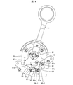
- FIG. 7 is a diagram illustrating a standby state of the ratchet mechanism 80 in which the start lever 11 is at the home position HP.
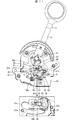
- FIG. 8 is a diagram illustrating a one-step rotation state of the ratchet mechanism 80 in which the start lever 11 is pulled down one step from the home position HP.
- FIG. 9 is a view for explaining the rotation state of the ratchet mechanism 80 one step before the final step, in which the start lever 11 is pulled down to one step before the end position EP.
- FIG. 10 is a diagram for explaining a reset state of the ratchet mechanism 80 in which the start lever 11 is pulled down to the end position EP.
- the engaging portion 83a of the ratchet piece 83 is engaged with the tooth root portion 86-1 of the rotating plate 81.
- the engaging portion 84 a of the ratchet piece 84 does not mesh with any tooth root portion 86.
- the reset piece 91 of the reset mechanism 90 is in a set position where it does not contact the ratchet pieces 83 and 84.
- the reset piece 91 When the start lever 11 is further lowered by one step from the state shown in FIG. 9 to reach the end position EP, the reset piece 91 is pushed by the protrusion 81b formed on the rotating plate 81 as shown in FIG. It rotates counterclockwise around 95 and moves to the reset position. As a result, the release portion 91a pushes down the ratchet pieces 83 and 84, and the meshing between the ratchet pieces 83 and 84 and the rotary plate 81 is released. When the restriction by the ratchet mechanism 80 is released, the start lever 11 automatically returns to the home position HP by the force of the biasing spring.
- FIG. 11 is a perspective view of the main part of the handle module 20 for explaining the configuration of the reset piece urging disk 93 and the reset piece urging disk guide 94 of the reset mechanism 90.
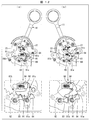
- 12A and 12B are diagrams for explaining the operation of the reset mechanism.
- FIG. 12A shows a state where the reset piece 91 is in the set position
- FIG. 12B shows a state where the reset piece 91 is in the reset position. Yes.
- the reset mechanism 90 includes a reset piece 91, a ratchet mechanism cover 92, a reset piece biasing disk 93, and a reset piece biasing disk guide 94.
- the reset piece 91 is an L-shaped plate, and the upper end portion of the L-shaped vertical line portion is pivotally supported by the shaft 95 along the inner surface of the rotating plate 81.
- the reset piece 91 is pivotally supported about the shaft 95 as a fulcrum.
- the start lever 11 With the movement of the start lever 11, the reset piece 91 hits the protrusions 81b and 81c when formed on the rotating plate 81, and the start lever further moves in that state, so that the shaft 95 rotates around the shaft 95, Switches from the set position to the reset position.
- the bottom surface of the L-shaped horizontal line portion in the reset piece 91 functions as a release portion 91a that releases the meshing between the ratchet pieces 83 and 84 and the rotating plate 81 by pushing down the ratchet pieces 83 and 84 at the reset position.
- the release portion 91a is formed in a shape that does not interfere with the ratchet pieces 83 and 84 at the set position.
- the shaft 95 on which the reset piece 91 is pivotally supported projects from the inside of the frame 23 to the inside of the rotating plate 81 through a long hole 81 a formed in the rotating plate 81.
- the elongated hole 81a has a length and a shape that do not hinder the rotation of the rotating plate 81 when the start lever 11 moves from the home position HP to the end position EP.
- the reset piece urging disk 93 is provided coaxially with the reset piece 91 and moves together with the reset piece 91.
- the reset piece biasing disk 93 is engaged with the reset piece biasing disk guide 94 to bias the reset piece 91 to the set position or the reset position.
- the reset piece biasing disk guide 94 is provided with a mountain-shaped boss guide portion 94 a that protrudes toward the shaft 95 of the reset piece 91 (see the enlarged view of FIG. 11).
- the spring 96 is omitted).
- the boss 93a of the reset piece urging disk 93 that rotates together with the reset piece 91 is guided and held above (set position) or below (reset position) the boss guide section 94a along the boss guide section 94a.
- the reset piece 91 holds the set position by holding the boss 93a on the boss guide portion 94a. In a state where the reset piece 91 is in the set position, the release portion 91a does not contact the ratchet pieces 83 and 84.
- the reset piece 91 holds the reset position by holding the boss 93a below the boss guide portion 94a. In a state where the reset piece 91 is in the reset position, the release portion 91a pushes down the ratchet pieces 83 and 84. As a result, the meshing between the ratchet pieces 83 and 84 and the rotating plate 81 is released.
- the reset piece urging disk guide 94 is attached to a ratchet mechanism cover 92 disposed so as to cover the ratchet mechanism 80.
- the reset piece urging disk guide 94 is configured to be slidable along the convex direction of the mountain-shaped boss guide portion 94a.
- the reset piece urging disk guide 94 is always urged in a direction in which the boss guide portion 94a protrudes by a spring 96 and a spring guide shaft 97 disposed therein.
- the reset piece biasing disk guide 94 engages with the boss 93a on the reset piece biasing disk 93 side to maintain the posture of the reset piece biasing disk 93, and the boss 93a gets over the boss guide portion 94a.
- the reset piece urging disk guide 94 moves against the urging force of the spring 96 to assist the ride-over operation.
- the ratchet mechanism 80 includes the two ratchet pieces 83 and 84 with respect to the rotating plate 81 that rotates integrally with the start lever 11, and these two ratchet pieces.
- 83 and 84 are configured to mesh with the tooth root portions 86 alternately at different timings while the rotating plate 81 moves by one pitch of the teeth 85.
- both of the two ratchet pieces 83 and 84 are configured to mesh with one of the tooth root portions 86 at different timings.
- the pitch of the teeth 85 can be doubled when the number of steps (the number of steps) is the same as in the conventional configuration in which only one ratchet piece is provided on the rotating plate.
- the pitch of the teeth 85 can be made twice as large (rough), so that the depth of the root portion 86 can be increased, and various operations can be performed by changing the depth of engagement and the shape of the teeth 85. A feeling can be provided.
- the pitch of the teeth 85 can be increased (rough), the strength of the meshing portion can be increased, and the required strength can be easily ensured.
- a configuration in which two ratchet pieces 83 and 84 are provided for one rotating plate 81 is illustrated, but a configuration in which three or more ratchet pieces are provided may be used. In the configuration in which three ratchet pieces are provided, the tooth pitch of the rotating plate can be tripled.
- the distance from the engagement portion of the reference ratchet piece is (N + 1/3) times the pitch of the teeth of the rotating plate ( N + 2/3) times.
- N is 0 and a natural number.
- the rotating plate is configured so that the engaging portions of all the ratchet pieces alternatively mesh with any of the teeth. What is necessary is just to arrange
- a lever unit includes a lever that is rotatable with respect to a shaft, a ratchet mechanism that restricts the movement direction of the lever in one direction, and a reset mechanism that releases the restriction of the movement direction by the ratchet mechanism.
- the ratchet mechanism includes a rotating body that rotates integrally with the lever and has a plurality of teeth formed on an outer edge thereof, and a meshing portion that engages with a tooth root portion between the teeth of the rotating body.
- a plurality of pawl pieces each having a joint portion, and each of the pawl pieces is configured so that the engaging portions of all the pawl pieces are alternatively selected each time the rotating body moves by one pitch of the teeth. It arrange
- each of the plurality of pawl pieces rotates so that the engaging portions of all the pawl pieces alternatively mesh with any one of the tooth roots each time the rotating body moves by one pitch of the tooth. It is arranged along the outer edge of the body. Therefore, a tactile feel can be obtained by the number of pawl pieces provided by moving the rotating body for one pitch. That is, the number of steps corresponding to the number of pawl pieces provided can be secured by moving the rotating body for one pitch.
- the tooth pitch can be doubled when the number of steps is the same as in the conventional configuration in which only one pawl piece is provided.
- the structure provided with three pawl pieces it can be tripled.
- the tooth pitch can be increased to 2 or 3 times (rougher) so that the depth of the root can be increased, and various operations can be performed by changing the mesh depth and tooth shape. A feeling can be provided. Further, since the tooth pitch can be increased (roughly) twice or three times, it is easy to ensure the necessary strength at the meshing portion.
- the release mechanism further includes a release piece that contacts and presses each of the plurality of pawl pieces and separates the engaging portion from an outer edge of the rotating body. You can also.
- the engagement portions of the plurality of pawl pieces can be collectively separated from the rotating body with one release piece. Therefore, the reset mechanism can be simplified as compared with the configuration in which the release pieces are provided corresponding to the plurality of pawl pieces.
- the present invention can be used for a gaming machine equipped with a lever provided so as to be bi-directionally rotatable with respect to an axis such as a slot machine.
Landscapes
- Physics & Mathematics (AREA)
- General Physics & Mathematics (AREA)
- Engineering & Computer Science (AREA)
- Automation & Control Theory (AREA)
- Slot Machines And Peripheral Devices (AREA)
- Transmission Devices (AREA)
Abstract
固定軸(21)に対して回転可能に設けられたスタートレバー(11)と、該スタートレバー(11)の移動方向を一方向に制限するラチェット機構(80)と、該ラチェット機構(80)による移動方向の制限を解除するリセット機構(90)とを備えたレバーユニットであって、ラチェット機構(80)は、スタートレバー(11)と一体に回転し、外縁に複数の歯(85)が形成された回転プレート(81)と、該回転プレート(81)の前記歯(85)の間の歯谷部(86)に噛み合う係合部(83a,84a)を有する複数のラチェット片(83,84)を備え、複数のラチェット片(83,84)は、回転プレート(81)が歯(85)の1ピッチ分移動する毎に、全てのラチェット片(83,84)の係合部(83a,84a)が択一的に何れかの歯谷部(86)と噛み合うように、回転プレート(81)の外縁に沿って配設されている。
Description
本発明は、スロットマシン等の遊技機に備えられるレバーユニットに関するものである。
遊技機の一種であるスロットマシンでは、複数種類のシンボルが表示された複数のリールが回転する。そして、リールが停止したときに、窓に表示されているシンボルの揃い方およびその揃っているシンボルにより役が決定する。遊技者には、決定した役とベット数(賭け数)とに応じて賞が付与される。リールは、スロットマシンに備えられた、回転開始ボタンあるいは回転開始レバーが操作されることで回転を開始する。カジノ等に設置されているスロットマシンでは、機器の制御によってリールは自動停止する。
ところで、カジノ等の遊技施設では、1つの遊技機メーカが製造したスロットマシンだけでなく、様々な遊技機メーカのスロットマシンが設置される。遊技者は、その中から嗜好のあったマシンを選択して遊技を行う。そのため、遊技施設は、遊技者に人気のあるスロットマシンを設置して、競合する他の遊技施設に対する優位性の確保を図る。また、遊技機メーカは、遊技者にアピールできるスロットマシンを提供できるよう開発を続ける。
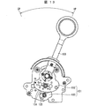
このような中、本願出願人は、リールの回転開始レバーとして用いることのできる、レバーユニットを発明し、本件よりも先に出願している(特許文献1)。このレバーユニットは、図13に示すように、スタートレバー100とラチェット機構101とを備えている。スタートレバー100の動作方向は、ラチェット機構101により、ホームポジションHPからエンドポジションEPに向かう一方向に制限される。
ラチェット機構101は、回転プレート102とラチェット片103とを備える。回転プレート102は、スタートレバー100と一体に回転し、その外縁に鋸歯状に複数の歯104が形成されている。一方、ラチェット片103は、回転プレート102の外周に回転自在に設けられ、歯104と歯104との間の歯谷部105に噛み合うように付勢されている。
スタートレバー100を引き下げると、回転プレート102が回転し、ラチェット片103と噛み合う歯谷部105が1つずつ段階的に切り換わっていく。これにより、スタートレバー100の操作者は、カチカチとした小気味好い感触を得ることができる。一方、ラチェット片103が歯谷部105と噛み合った状態で、スタートレバー100を引き上げる方向へ移動させようとしても、歯104がラチェット片103に当たって、回転プレート102を回転させることができない。
スタートレバー100がエンドポジションに到達すると、ラチェット片103と歯谷部105との噛み合いは解除される。これにより、スタートレバー100はホームポジションへ復帰できる。
しかしながら、特許文献1の構成では、小気味好い感触とラチェット機構の強度確保とを実現することが難しい、といった改善点を有している。その理由を説明する。
特許文献1の構成では、スタートレバー100の回転中心からの長さに比べて、歯104の回転中心からの距離が短い。そのため、1ステップあたりの回転プレート102の回転距離(歯104が形成されている外縁部分の移動距離)が小さく、歯104は細かいピッチに設定されている。なお、1ステップとは、スタートレバー100を操作した際に得られる1段階に相当する。
特許文献1の構成では、細かいピッチを実現するために、ラチェット機構における噛み合い形状が小さく作られている。しかしながら、噛み合い形状を小さくすると、カチカチとした感触が小さくなってしまい、また、噛み合い部分の強度も小さくなってしまう。そのため、小気味好い感触が得にくくなり、ラチェット機構の強度確保も難しくなる。
本発明は、上記課題に鑑みなされたものであり、その目的は、1ステップあたりの回転板の回転距離が小さくても、小気味好い感触とラチェット機構の強度確保とを同時に実現できるレバーユニットを提供することにある。
前記の課題を解決するために、本発明のレバーユニットは、軸に対して回転可能に設けられたレバーと、該レバーの移動方向を一方向に制限するラチェット機構と、該ラチェット機構による移動方向の制限を解除するリセット機構とを備えたレバーユニットであって、前記ラチェット機構は、前記レバーと一体に回転し、外縁に複数の歯が形成された回転体と、前記回転体の前記歯の間の歯谷部に噛み合う係合部を有する複数の歯止め片を備え、前記複数の歯止め片は、前記回転体が前記歯の1ピッチ分移動する毎に、全ての前記歯止め片の前記係合部が択一的に何れかの前記歯谷部と噛み合うように、前記回転体の外縁に沿って配設されている。
本発明によれば、1ステップあたりの回転板の回転距離が小さくても、小気味好い感触とラチェット機構の強度確保とを同時に実現できるレバーユニットを提供できるという効果を奏する。
以下、本発明の実施の形態について詳細に説明する。本実施の形態では、カジノ等の遊技ホールに設置される遊技機としてのスロットマシンに搭載されたレバーユニットを例示する。
<スロットマシンの構成>
図1は、本実施の形態に係るレバーユニット10を搭載したスロットマシン1の概観斜視図である。図1に示すように、スロットマシン1は、遊技者(操作者)と対峙する前面の中央部にリール部5が設けられている。
図1は、本実施の形態に係るレバーユニット10を搭載したスロットマシン1の概観斜視図である。図1に示すように、スロットマシン1は、遊技者(操作者)と対峙する前面の中央部にリール部5が設けられている。
リール部5には、複数種類のシンボルが表示された複数のリール(図示せず)が備えられている。複数のリールは、遊技者がスタートレバー(レバー)11を操作することで回転を開始し、機器の制御によって自動に停止する。リールが停止したときにリール部5の窓(図示せず)に表示されているシンボルの揃い方とその揃っているシンボルとによって役が決定する。遊技者には、決定した役とベット数(賭け数)とに応じて賞が付与される。なお、リール部5の構成としては、リールが実際に設けられている構成の他、リール部5が液晶画面等の表示画面より構成されていて、リールに相当する画像が表示されている構成などであってもよい。
リール部5の下方には、複数の押圧式のスイッチからなるスイッチ部7およびスタートレバー11が設けられている。スイッチ部7およびスタートレバー11は、遊技者からの操作を受け付けるものである。スイッチ部7は、遊技者がスロットマシン1をプレイするときのベット数の指定を受け付ける。スタートレバー11は、リール部5におけるリールの回転開始の指示を受け付ける。これらスイッチ部7およびスタートレバー11は、スロットマシン1の筐体3が遊技者に向かって迫出すように設けられた迫出し部3aに併設されている。
なお、図1では、スタートレバー11をスロットマシン1の前面の右側に配置した構成を例示しているが、左側に配置する構成であってもよい。本実施の形態のスロットマシン1は、このスタートレバー11の構成に特徴があり、以下、これについて詳細に説明する。
<レバーユニットの構成>
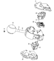
スタートレバー11は、レバーユニット10の一構成部材である。レバーユニット10は、スロットマシン1の筐体3における前記した迫出し部3aに取り付けられている。図2に、本実施の形態に係るレバーユニット10の外観斜視図を示し、図3に、該レバーユニット10の分解斜視図を示す。
スタートレバー11は、レバーユニット10の一構成部材である。レバーユニット10は、スロットマシン1の筐体3における前記した迫出し部3aに取り付けられている。図2に、本実施の形態に係るレバーユニット10の外観斜視図を示し、図3に、該レバーユニット10の分解斜視図を示す。
図2、図3に示すように、レバーユニット10は、スタートレバー11を備えるハンドルモジュール20に、ノックモジュール40、ロックモジュール50、エンコーダ基板モジュール60が取り付けられ、両サイドが、サイドカバー70,71で覆われている。
ハンドルモジュール20は、スタートレバー11を、ホームポジションHPとエンドポジションEPとの間(図2参照)で双方向に移動自在に支持するものであり、詳細については後述する。
ノックモジュール40は、ソレノイド(図示せず)にて搖動されるノッカ41を備えている。ノックモジュール40は、ノッカ41にて、スタートレバー11と一体化された後述する回転プレート81を叩いて、スタートレバー11に振動・衝撃を与える。
ロックモジュール50は、回転プレート81に係合させてスタートレバー11をロックするロック部材51を備えている。ロックモジュール50は、スロットマシン1を利用した遊技に関係があるとき以外は、スタートレバー11をロックして、操作を不能にする。
エンコーダ基板モジュール60は、複数のフォトマイクロセンサ(図示せず)を備えている。エンコーダ基板モジュール60は、複数のフォトマイクロセンサにて、スタートレバー11の位置を検出する。
<ハンドルモジュールの構成>
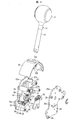
図4に、レバーユニット10におけるハンドルモジュール20の分解斜視図を示す。図4に示すように、ハンドルモジュール20は、スタートレバー11と、支持部材27と、ラチェット機構80と、リセット機構90とを備えている。
図4に、レバーユニット10におけるハンドルモジュール20の分解斜視図を示す。図4に示すように、ハンドルモジュール20は、スタートレバー11と、支持部材27と、ラチェット機構80と、リセット機構90とを備えている。
スタートレバー11は、シャフト13の先端部に球状のグリップ12を有する。シャフト13の基端側は、外装カバー33に設けられた穴33aを介して支持部材27の嵌合部27aに嵌合されてネジ止めされている。これにより、スタートレバー11は、外装カバー33と共に、支持部材27に固定され、支持部材27と一体化されている。
支持部材27は、スタートレバー11を一対のフレーム23,25に対して回転自在に支持するものである。支持部材27は、スタートレバー11のシャフト13の軸方向と直角をなす方向に貫通する軸穴27bを有している。この軸穴27bに、一対のフレーム23,25に固定された固定軸21が挿通されている。これにより、支持部材27は、固定軸21に対して回転自在となり、ひいては、該支持部材27を介して、支持部材27に固定されたスタートレバー11および外装カバー33も、固定軸21に対して回転自在となる。そして、支持部材27は、図示しない付勢バネによって、常に、スタートレバー11をホームポジションHPに戻す方向に付勢されている。
なお、本実施の形態では、固定軸21が一対のフレーム23,25に固定されており、該固定軸21に対して支持部材27が回転する構成を例示している。しかしながら、固定軸21が支持部材27に固定されており、固定軸21が一対のフレーム23,25に対して回転自在に構成されていてもよい。
一対のフレーム23,25は、複数の固定部24を介してネジ26にて固定されており、所定の間隔を保持している。これらフレーム23,25は、相似の外縁形状を有している。フレーム23,25の上部外縁は、固定軸21を中心とした円弧を描く、外装カバー33の摺動領域23a,25aとなっている。外装カバー33の内側には、上記摺動領域23a,25aを摺動するガイド部33b,33bが設けられている。
また、これらフレーム23,25のうち、外側にノックモジュール40が取り付けられるフレーム23には、ノックモジュール40のノッカ41をフレーム23の内側に覗かせるための開口23cが形成されている。
また、外側にエンコーダ基板モジュール60が取り付けられるフレーム25には、エンコーダ基板モジュール60がスタートレバー11の位置の検出に用いる検出片27cをフレーム25の外側に覗かせるための開口25cが形成されている。検出片27cは、支持部材27に取り付けられており、スタートレバー11と一体的に移動する。
ラチェット機構80は、スタートレバー11の動作方向を一方向に制限するものである。ラチェット機構80は、回転体としての回転プレート81と、複数の歯止め片としての2つのラチェット片83,84とを備えている。
リセット機構90は、ラチェット機構80によるスタートレバー11の動作方向の制限を解除するものである。リセット機構90は、解除片としてのリセット片91と、ラチェット機構カバー92と、後述するリセット片付勢ディスク93と、リセット片付勢ディスクガイド94とを備えている。
<ラチェット機構80の構成>
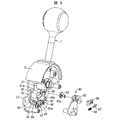
図5、図6を用いて、ラチェット機構80の構成について説明する。図5は、ハンドルモジュール20に搭載されたラチェット機構80とリセット機構90の構成を説明するためのハンドルモジュール20の要部の分解斜視図である。図6は、ラチェット機構80とリセット機構90の構成を説明するためのハンドルモジュール20の要部の斜視図である。
図5、図6を用いて、ラチェット機構80の構成について説明する。図5は、ハンドルモジュール20に搭載されたラチェット機構80とリセット機構90の構成を説明するためのハンドルモジュール20の要部の分解斜視図である。図6は、ラチェット機構80とリセット機構90の構成を説明するためのハンドルモジュール20の要部の斜視図である。
図5、図6に示すように、ラチェット機構80は、回転プレート81と、2つのラチェット片83,84とを備えている。回転プレート81は、フレーム23の内側面に沿った状態で、支持部材27に取り付けられている。これにより、回転プレート81は、固定軸21を中心として、スタートレバー11と一体に動く。回転プレート81の外縁には、複数の歯85が鋸歯状に形成されている。
歯85のピッチは、必要な強度や感触、およびラチェット機構80に割り当てることができる空間などに基づいて決定される。レバーユニット10が搭載されるスロットマシン1側の空間的制約から、ラチェット機構80に割り当てられる空間が小さい場合、回転プレート81は小さくなり、固定軸21から歯85が形成されている外縁までの長さが、スタートレバー11の固定軸21からの長さに対して小さくなる。本実施形態のレバーユニット10においては、回転プレート81における固定軸21から歯85が形成されている外縁までの長さは、スタートレバー11の固定軸21からの長さの1/3以下(例えば、1/3.8)に設定されている。
ラチェット片83,84は、回転プレート81における複数の歯85が形成されている部分の外周に、その移動方向に沿って並んで配設されている。ラチェット片83,84は、フレーム23の内側に突設された軸87,88に回転自在に軸支され、常時付勢されている。付勢の方向は、スタートレバー11を引き下げに伴って回転プレート81に形成された複数の歯85が移動する方向とは逆の方向である。また、ラチェット片83,84には、回転プレート81の歯谷部86(歯85の間)に噛み合う係合部83a,84aが設けられている。
そして、これらラチェット片83,84は、回転プレート81が歯85の1ピッチ分移動する毎に、両方のラチェット片83,84の係合部83a,84aが択一的に何れかの歯谷部86と噛み合うように、回転プレート81の外縁に沿って配設されている。これにより、回転プレート81が歯85の1ピッチ分移動する間に、2つのラチェット片83,84の83a,84aが、タイミングをずらして何れかの歯谷部86に噛み合うこととなる。
具体的には、2つのラチェット片83,84の係合部83a,84aの間隔が、歯85のピッチの(N+0.5)倍に設定されている。Nは、0および自然数である。これにより、2つのラチェット片83,84が同時に歯谷部86に噛み合うことはなく、回転プレート81が歯のピッチの1/2の距離回転する毎に、交互に噛み合うこととなる。図5、図6に示す構成では、係合部83a,84aの間隔は、ピッチPの2.5倍に設定されている。
歯85と噛み合った状態のラチェット片83,84は、回転プレート81が回転すると、噛み合っていた歯谷部86に隣り合う歯85によって付勢力に抗って押下げられることで噛み合いを解除し、次の歯谷部86と噛み合う。このような噛み合いとその解除を繰り返すことで、噛み合う歯谷部86を順次切り替えていき、スタートレバー11の引下げ方向への回転を可能にする。そして、このとき、スタートレバー11の操作者は、カチカチとした小気味好い感触を得ることができる。
また、支持部材27に設けられた付勢バネにより、スタートレバー11には常時、ホームポジションHPに戻す方向の力が加わっている。しかしながら、ラチェット片83,84の何れかが歯谷部86と常に噛み合っており、噛み合っている歯谷部86に隣り合う歯85と噛み合っているラチェット片83あるいは84とが当接するため、回転プレート81が回転することはない。
<ラチェット機構80の動作>
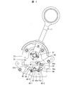
次に、図7~図10を用いて、ラチェット機構80の動作を説明する。図7は、スタートレバー11がホームポジションHPにある、ラチェット機構80の待機状態を説明する図である。図8は、スタートレバー11がホームポジションHPから1段引き下げられた、ラチェット機構80の1ステップ回転状態を説明する図である。図9は、スタートレバー11がエンドポジションEPの1段手前まで引き下げられた、ラチェット機構80の最終ステップ1つ前の回転状態を説明する図である。図10は、スタートレバー11がエンドポジションEPまで引き下げられた、ラチェット機構80のリセット状態を説明する図である。
次に、図7~図10を用いて、ラチェット機構80の動作を説明する。図7は、スタートレバー11がホームポジションHPにある、ラチェット機構80の待機状態を説明する図である。図8は、スタートレバー11がホームポジションHPから1段引き下げられた、ラチェット機構80の1ステップ回転状態を説明する図である。図9は、スタートレバー11がエンドポジションEPの1段手前まで引き下げられた、ラチェット機構80の最終ステップ1つ前の回転状態を説明する図である。図10は、スタートレバー11がエンドポジションEPまで引き下げられた、ラチェット機構80のリセット状態を説明する図である。
図7に示すように、スタートレバー11がホームポジションHPにある、ラチェット機構80の待機状態では、ラチェット片83の係合部83aは回転プレート81の歯谷部86-1と噛み合っている。一方、ラチェット片84の係合部84aは何れの歯谷部86とも噛み合っていない。また、リセット機構90のリセット片91はラチェット片83,84に接触しないセット位置にある。
図7に示す状態から、スタートレバー11を1段階引き下げると、図8に示すように、ラチェット片83の係合部83aと歯谷部86-1との噛み合いが解除され、今度は、ラチェット片84の係合部84aが歯谷部86-2と噛み合う。スタートレバー11を1段階引き下げたときの回転プレート81の移動距離は、歯85のピッチの1/2である。
なお、図示してはいないが、図8に示す状態から、スタートレバー11をさらに1段階引き下げると、ラチェット片84の係合部84aと歯谷部86-2との噛み合いが解除され、今度は、ラチェット片83の係合部83aが歯谷部86-3(図7、図8参照)と噛み合うこととなる。
このように、ラチェット機構80の構成によれば、回転プレート81が、歯85のピッチの1/2の距離移動する毎に、スタートレバー11を1段階引き下げることが可能になる。
そして、図9に示すように、スタートレバー11がラチェット機構80の最終ステップ1つ前まで引き下げられると、ラチェット片83の係合部83aは、回転プレート81の最終断の歯谷部86-4と噛み合う。一方、ラチェット片84の係合部84aは何れの歯谷部86とも噛み合わない。また、この状態で、リセット片91は、回転プレート81に形成された突起81bに当接する。
図9に示す状態から、スタートレバー11をさらに1段階引き下げてエンドポジションEPに達すると、図10に示すように、リセット片91が、回転プレート81に形成された突起81bに押されて、軸95を中心に反時計周りに回転し、リセット位置へと移動する。これにより、解除部91aがラチェット片83,84を押下げて、ラチェット片83,84と回転プレート81との噛み合いが解除される。スタートレバー11は、ラチェット機構80による制限が解除されると、付勢バネの力によって、ホームポジションHPまで自動復帰する。
<リセット機構90の構成>
次に、前述の図5および図6と、図11、図12を用いて、リセット機構90の構成について説明する。図11は、リセット機構90のリセット片付勢ディスク93とリセット片付勢ディスクガイド94の構成を説明するためのハンドルモジュール20の要部の斜視図である。図12は、リセット機構の動作を説明するための図であり、(a)は、リセット片91がセット位置にある状態を示し、(b)はリセット片91がリセット位置にある状態を示している。
次に、前述の図5および図6と、図11、図12を用いて、リセット機構90の構成について説明する。図11は、リセット機構90のリセット片付勢ディスク93とリセット片付勢ディスクガイド94の構成を説明するためのハンドルモジュール20の要部の斜視図である。図12は、リセット機構の動作を説明するための図であり、(a)は、リセット片91がセット位置にある状態を示し、(b)はリセット片91がリセット位置にある状態を示している。
図5、図6に示すように、リセット機構90は、リセット片91と、ラチェット機構カバー92と、リセット片付勢ディスク93と、リセット片付勢ディスクガイド94とを備えている。
リセット片91は、L字状のプレートであり、回転プレート81の内側面に沿った状態で、L字状の縦線部の上端部が軸95に軸支されている。リセット片91は、リセット片91に力が加えられると、軸95を支点として回転可能に軸支されている。リセット片91は、スタートレバー11の移動に伴って、回転プレート81に形成されたと突起81b、81cに突き当たり、その状態でさらにスタートレバーが移動することで、軸95を支点として回転することで、セット位置からリセット位置へと相互に切り換わる。
リセット片91におけるL字状の横線部の底面は、リセット位置において、ラチェット片83,84を押下げて、ラチェット片83,84と回転プレート81との噛み合いを解除する解除部91aとして機能する。なお、解除部91aは、セット位置で、ラチェット片83,84と干渉しない形状に形成されている。
リセット片91が軸支される軸95は、フレーム23の内側から回転プレート81に形成された長穴81aを介して回転プレート81の内側へと突設されている。上記長穴81aは、スタートレバー11がホームポジションHPからエンドポジションEPまでの移動において、回転プレート81の回転を阻害しない長さと形状を有している。
リセット片付勢ディスク93は、リセット片91と同軸に設けられており、リセット片91と一体に動くものでる。リセット片付勢ディスク93は、リセット片付勢ディスクガイド94と係合して、リセット片91をセット位置またはリセット位置に付勢する。
図11に示すように、リセット片付勢ディスクガイド94には、リセット片91の軸95に向かって凸をなす山型のボス案内部94aが設けられている(図11の拡大図参照、拡大図ではバネ96を省略している)。リセット片91と共に回転するリセット片付勢ディスク93のボス93aが、このボス案内部94aに沿って、ボス案内部94aの上(セット位置)あるいは下(リセット位置)に案内されて保持される。
図12の(a)に示すように、ボス93aがボス案内部94aの上に保持されることで、リセット片91はセット位置を保持する。リセット片91がセット位置にある状態では、解除部91aはラチェット片83,84に接触しない。一方、図12の(b)に示すように、ボス93aがボス案内部94aの下に保持されることで、リセット片91はリセット位置を保持する。リセット片91がリセット位置にある状態では、解除部91aがラチェット片83,84を押下げる。これにより、ラチェット片83,84と、回転プレート81との噛み合いが解除される。
図11に示すように、上記リセット片付勢ディスクガイド94は、ラチェット機構80を覆うように配設されたラチェット機構カバー92に取り付けられている。リセット片付勢ディスクガイド94は、山型のボス案内部94aの凸を成す方向に沿ってスライド自在に構成されている。そして、リセット片付勢ディスクガイド94は、その内部に配設されたバネ96とバネガイド軸97とによって、常に、ボス案内部94aの凸をなす方向に付勢されている。これにより、リセット片付勢ディスクガイド94は、リセット片付勢ディスク93側のボス93aと係合して、リセット片付勢ディスク93の姿勢を保持すると共に、ボス93aがボス案内部94aを乗り越えるに際には、リセット片付勢ディスクガイド94はバネ96の付勢に抗って移動して、乗り越え動作を助けるようになっている。
以上のように、本実施の形態に係るレバーユニット10は、ラチェット機構80が、スタートレバー11と一体に回転する回転プレート81に対し、2つのラチェット片83,84を備え、これら2つのラチェット片83,84が、回転プレート81が歯85の1ピッチ分移動する間に、タイミングをずらして交互に歯谷部86と噛み合うよう構成されている。換言すると、回転プレート81が歯85の1ピッチ分移動する毎に、2つのラチェット片83,84の両方共が、タイミングをずらして何れかの歯谷部86と噛み合うように構成されている。
これにより、歯85の1ピッチ分の回転プレート81の移動で、2つのラチェット片83,84が噛み合う2回分のカチカチとした感触を得ることができる。したがって、回転プレートに対してラチェット片を1つのみ設けた従来構成と比較して、ステップ数(段数)を同じとした場合、歯85のピッチを2倍にできる。
そして、歯85のピッチを2倍と大きく(粗く)できることで、歯谷部86の深さを深くすることが可能になり、噛み合いの深さや、歯85の形状を変化させて、様々な操作感を提供することができる。また、歯85のピッチを大きく(粗く)できることで、噛み合い部分の強度を上げることができ、必要な強度の確保が容易になる。
なお、本実施の形態では、1つの回転プレート81に対して、2つのラチェット片83,84を設けた構成を例示したが、3つ以上のラチェット片を設ける構成であってもよい。ラチェット片を3つ設けた構成では、回転プレートの歯のピッチを3倍にできる。
ラチェット片を3つ設けた構成では、3つのうちの1つを基準として、該基準のラチェット片の係合部との間隔が、回転プレートの歯のピッチの(N+1/3)倍と、(N+2/3)倍とに、それぞれ設定される。Nは、0および自然数である。これにより、3つのラチェット片が同時に歯谷部に噛み合うことはなく、回転プレートが歯のピッチの1/3の距離回転する毎に、交互に噛み合うこととなる。
要は、複数のラチェット片を、回転プレートが歯の1ピッチ分移動する毎に、その全てのラチェット片の係合部が、択一的に何れかの歯谷部と噛み合うように、回転プレートの外縁に沿って配設すればよい。
〔まとめ〕
本発明に係るレバーユニットは、軸に対して回転可能に設けられたレバーと、該レバーの移動方向を一方向に制限するラチェット機構と、該ラチェット機構による移動方向の制限を解除するリセット機構とを備えたレバーユニットであって、前記ラチェット機構は、前記レバーと一体に回転し、外縁に複数の歯が形成された回転体と、前記回転体の前記歯の間の歯谷部に噛み合う係合部を有する複数の歯止め片を備え、前記複数の歯止め片は、前記回転体が前記歯の1ピッチ分移動する毎に、全ての前記歯止め片の前記係合部が択一的に何れかの前記歯谷部と噛み合うように、前記回転体の外縁に沿って配設されていることを特徴としている。
本発明に係るレバーユニットは、軸に対して回転可能に設けられたレバーと、該レバーの移動方向を一方向に制限するラチェット機構と、該ラチェット機構による移動方向の制限を解除するリセット機構とを備えたレバーユニットであって、前記ラチェット機構は、前記レバーと一体に回転し、外縁に複数の歯が形成された回転体と、前記回転体の前記歯の間の歯谷部に噛み合う係合部を有する複数の歯止め片を備え、前記複数の歯止め片は、前記回転体が前記歯の1ピッチ分移動する毎に、全ての前記歯止め片の前記係合部が択一的に何れかの前記歯谷部と噛み合うように、前記回転体の外縁に沿って配設されていることを特徴としている。
上記構成によれば、複数の歯止め片が、回転体が歯の1ピッチ分移動する毎に、全ての歯止め片の係合部が択一的に何れかの歯谷部と噛み合うように、回転体の外縁に沿って配設されている。したがって、1ピッチ分の回転体の移動で、設けた歯止め片の数だけ、カチカチとした感触を得ることができる。つまり、1ピッチ分の回転体の移動で、設けた歯止め片の数に相当するステップ数を確保できる。
これにより、例えば、歯止め片を2つ設けた構成では、歯止め片を1つのみ設けた従来構成と比較して、ステップ数を同じとした場合、歯のピッチを2倍にできる。歯止め片を3つ設けた構成では、3倍にできる。
そして、歯のピッチを2倍,3倍と大きく(粗く)できることで、歯谷部の深さを深くすることが可能になり、噛み合いの深さや、歯の形状を変化させて、様々な操作感を提供することができる。また、歯のピッチを2倍,3倍と大きく(粗く)できることで、噛み合い部分における必要な強度の確保が容易になる。
本発明に係るレバーユニットは、さらに、前記解除機構は、前記複数の歯止め片それぞれと接触して押圧し、前記回転体の外縁から前記係合部を離間させる解除片を備えている構成とすることもできる。
上記構成によれば、1つの解除片にて、複数の歯止め片の係合部を一括して回転体から離間させることができる。したがって、複数の歯止め片に対応して解除片を設ける構成に比べて、リセット機構を簡素化できる。
本発明は上述した各実施形態に限定されるものではなく、請求項に示した範囲で種々の変更が可能であり、異なる実施形態にそれぞれ開示された技術的手段を適宜組み合わせて得られる実施形態についても本発明の技術的範囲に含まれる。
本発明は、スロットマシンのような軸に対して双方向に回転自在に設けられたレバーを備えた遊技機等に利用することができる。
1 スロットマシン
10 レバーユニット
11 スタートレバー(レバー)
20 ハンドルモジュール
21 固定軸
23,25 フレーム
27 支持部材
80 ラチェット機構
81 回転プレート(回転体)
83 ラチェット片
83,84 ラチェット片(歯止め片)
83a,84a 係合部
85 歯
86 歯谷部
90 リセット機構
91 リセット片(解除片)
91a 解除部
95 軸
10 レバーユニット
11 スタートレバー(レバー)
20 ハンドルモジュール
21 固定軸
23,25 フレーム
27 支持部材
80 ラチェット機構
81 回転プレート(回転体)
83 ラチェット片
83,84 ラチェット片(歯止め片)
83a,84a 係合部
85 歯
86 歯谷部
90 リセット機構
91 リセット片(解除片)
91a 解除部
95 軸
Claims (2)
- 軸に対して回転可能に設けられたレバーと、該レバーの移動方向を一方向に制限するラチェット機構と、該ラチェット機構による移動方向の制限を解除するリセット機構とを備えたレバーユニットであって、
前記ラチェット機構は、
前記レバーと一体に回転し、外縁に複数の歯が形成された回転体と、
前記回転体の前記歯の間の歯谷部に噛み合う係合部を有する複数の歯止め片を備え、
前記複数の歯止め片は、前記回転体が前記歯の1ピッチ分移動する毎に、全ての前記歯止め片の前記係合部が択一的に何れかの前記歯谷部と噛み合うように、前記回転体の外縁に沿って配設されていることを特徴とするレバーユニット。 - 前記リセット機構は、前記複数の歯止め片それぞれと接触して押圧し、前記回転体の外縁から前記係合部を離間させる解除片を備えていることを特徴とする請求項1に記載のレバーユニット。
Priority Applications (3)
| Application Number | Priority Date | Filing Date | Title |
|---|---|---|---|
| PCT/JP2015/058605 WO2016151709A1 (ja) | 2015-03-20 | 2015-03-20 | レバーユニット |
| US15/553,000 US10216216B2 (en) | 2015-03-20 | 2015-03-20 | Lever unit |
| DE112015006340.4T DE112015006340T5 (de) | 2015-03-20 | 2015-03-20 | Hebeleinheit |
Applications Claiming Priority (1)
| Application Number | Priority Date | Filing Date | Title |
|---|---|---|---|
| PCT/JP2015/058605 WO2016151709A1 (ja) | 2015-03-20 | 2015-03-20 | レバーユニット |
Publications (1)
| Publication Number | Publication Date |
|---|---|
| WO2016151709A1 true WO2016151709A1 (ja) | 2016-09-29 |
Family
ID=56978079
Family Applications (1)
| Application Number | Title | Priority Date | Filing Date |
|---|---|---|---|
| PCT/JP2015/058605 Ceased WO2016151709A1 (ja) | 2015-03-20 | 2015-03-20 | レバーユニット |
Country Status (3)
| Country | Link |
|---|---|
| US (1) | US10216216B2 (ja) |
| DE (1) | DE112015006340T5 (ja) |
| WO (1) | WO2016151709A1 (ja) |
Families Citing this family (2)
| Publication number | Priority date | Publication date | Assignee | Title |
|---|---|---|---|---|
| JP6899545B2 (ja) * | 2017-01-27 | 2021-07-07 | 日本発條株式会社 | サイドマウント形の機関制御装置 |
| US12482325B2 (en) * | 2023-07-25 | 2025-11-25 | Aristocrat Technologies, Inc. | Reverse drive protection assembly for a gaming machine handle |
Citations (3)
| Publication number | Priority date | Publication date | Assignee | Title |
|---|---|---|---|---|
| JPH11348740A (ja) * | 1998-06-10 | 1999-12-21 | Akebono Brake Res & Dev Center Ltd | パーキングブレーキ装置 |
| JP2002307318A (ja) * | 2001-04-17 | 2002-10-23 | Kyoto Tool Co Ltd | ラチェットレンチ |
| JP2014212813A (ja) * | 2013-04-22 | 2014-11-17 | オムロン株式会社 | レバーユニット |
Family Cites Families (3)
| Publication number | Priority date | Publication date | Assignee | Title |
|---|---|---|---|---|
| US1454398A (en) * | 1922-05-17 | 1923-05-08 | Mackenzie Philip | Pawl-and-ratchet power appliance |
| US2669883A (en) * | 1951-01-31 | 1954-02-23 | American Forging & Socket Co | Brake lever assembly |
| US3581586A (en) * | 1968-04-19 | 1971-06-01 | Walter L Blackburn | Ratchet winch |
-
2015
- 2015-03-20 WO PCT/JP2015/058605 patent/WO2016151709A1/ja not_active Ceased
- 2015-03-20 US US15/553,000 patent/US10216216B2/en active Active
- 2015-03-20 DE DE112015006340.4T patent/DE112015006340T5/de active Pending
Patent Citations (3)
| Publication number | Priority date | Publication date | Assignee | Title |
|---|---|---|---|---|
| JPH11348740A (ja) * | 1998-06-10 | 1999-12-21 | Akebono Brake Res & Dev Center Ltd | パーキングブレーキ装置 |
| JP2002307318A (ja) * | 2001-04-17 | 2002-10-23 | Kyoto Tool Co Ltd | ラチェットレンチ |
| JP2014212813A (ja) * | 2013-04-22 | 2014-11-17 | オムロン株式会社 | レバーユニット |
Also Published As
| Publication number | Publication date |
|---|---|
| DE112015006340T5 (de) | 2017-11-30 |
| US20180032098A1 (en) | 2018-02-01 |
| US10216216B2 (en) | 2019-02-26 |
Similar Documents
| Publication | Publication Date | Title |
|---|---|---|
| JP5328945B2 (ja) | 遊技機 | |
| JP4887416B2 (ja) | 装飾体ユニット、遊技盤ユニット、及びパチンコ遊技機 | |
| JP5160968B2 (ja) | 遊技機 | |
| JP5140511B2 (ja) | 装飾体駆動ユニット、演出装置、遊技盤、及びパチンコ遊技機 | |
| JP5660649B1 (ja) | 遊技機用可動式演出装置及び遊技機 | |
| JP2010029470A (ja) | 分割型可動画像表示装置、遊技盤、及び遊技機 | |
| JP2010029372A (ja) | 分割型可動画像表示装置、遊技盤、及びパチンコ遊技機 | |
| JP5396229B2 (ja) | 遊技機用可動装置及びそれを備えた遊技機 | |
| JP2010029471A (ja) | 画像表示装置、遊技盤、及び遊技機 | |
| JP4699288B2 (ja) | 遊技機の可動式演出装置 | |
| JP5463171B2 (ja) | パチンコ機 | |
| JP5286348B2 (ja) | 遊技機 | |
| JP2007014407A (ja) | 遊技機の役物装置 | |
| JP2016220867A (ja) | 遊技機 | |
| JP4992620B2 (ja) | 遊技機 | |
| JP4941701B2 (ja) | 遊技機 | |
| JP5890640B2 (ja) | 遊技機 | |
| US10216216B2 (en) | Lever unit | |
| JP5800615B2 (ja) | 遊技機 | |
| JP4699289B2 (ja) | 遊技機の可動式演出装置 | |
| JP2010029371A (ja) | 分割型可動画像表示装置、遊技盤、及び遊技機 | |
| JP6869564B2 (ja) | 遊技機 | |
| JP6112586B1 (ja) | 遊技機 | |
| JP6745522B2 (ja) | 遊技機 | |
| JP4836022B2 (ja) | 遊技機 |
Legal Events
| Date | Code | Title | Description |
|---|---|---|---|
| 121 | Ep: the epo has been informed by wipo that ep was designated in this application |
Ref document number: 15886266 Country of ref document: EP Kind code of ref document: A1 |
|
| WWE | Wipo information: entry into national phase |
Ref document number: 112015006340 Country of ref document: DE |
|
| 122 | Ep: pct application non-entry in european phase |
Ref document number: 15886266 Country of ref document: EP Kind code of ref document: A1 |
|
| NENP | Non-entry into the national phase |
Ref country code: JP |