WO2016148138A1 - ドクターブレード装置、印刷装置、印刷方法、及び配線基板の製造方法 - Google Patents
ドクターブレード装置、印刷装置、印刷方法、及び配線基板の製造方法 Download PDFInfo
- Publication number
- WO2016148138A1 WO2016148138A1 PCT/JP2016/058152 JP2016058152W WO2016148138A1 WO 2016148138 A1 WO2016148138 A1 WO 2016148138A1 JP 2016058152 W JP2016058152 W JP 2016058152W WO 2016148138 A1 WO2016148138 A1 WO 2016148138A1
- Authority
- WO
- WIPO (PCT)
- Prior art keywords
- intaglio
- doctor blade
- conductive ink
- blade body
- blade device
- Prior art date
- Legal status (The legal status is an assumption and is not a legal conclusion. Google has not performed a legal analysis and makes no representation as to the accuracy of the status listed.)
- Ceased
Links
Images






Classifications
-
- B—PERFORMING OPERATIONS; TRANSPORTING
- B41—PRINTING; LINING MACHINES; TYPEWRITERS; STAMPS
- B41F—PRINTING MACHINES OR PRESSES
- B41F3/00—Cylinder presses, i.e. presses essentially comprising at least one cylinder co-operating with at least one flat type-bed
- B41F3/18—Cylinder presses, i.e. presses essentially comprising at least one cylinder co-operating with at least one flat type-bed of special construction or for particular purposes
- B41F3/20—Cylinder presses, i.e. presses essentially comprising at least one cylinder co-operating with at least one flat type-bed of special construction or for particular purposes with fixed type-beds and travelling impression cylinders
-
- B—PERFORMING OPERATIONS; TRANSPORTING
- B41—PRINTING; LINING MACHINES; TYPEWRITERS; STAMPS
- B41F—PRINTING MACHINES OR PRESSES
- B41F3/00—Cylinder presses, i.e. presses essentially comprising at least one cylinder co-operating with at least one flat type-bed
- B41F3/18—Cylinder presses, i.e. presses essentially comprising at least one cylinder co-operating with at least one flat type-bed of special construction or for particular purposes
- B41F3/36—Cylinder presses, i.e. presses essentially comprising at least one cylinder co-operating with at least one flat type-bed of special construction or for particular purposes for intaglio or heliogravure printing
- B41F3/38—Wiping mechanisms
-
- B—PERFORMING OPERATIONS; TRANSPORTING
- B41—PRINTING; LINING MACHINES; TYPEWRITERS; STAMPS
- B41F—PRINTING MACHINES OR PRESSES
- B41F9/00—Rotary intaglio printing presses
- B41F9/06—Details
- B41F9/08—Wiping mechanisms
- B41F9/10—Doctors, scrapers, or like devices
-
- B—PERFORMING OPERATIONS; TRANSPORTING
- B41—PRINTING; LINING MACHINES; TYPEWRITERS; STAMPS
- B41M—PRINTING, DUPLICATING, MARKING, OR COPYING PROCESSES; COLOUR PRINTING
- B41M1/00—Inking and printing with a printer's forme
- B41M1/10—Intaglio printing ; Gravure printing
-
- H—ELECTRICITY
- H05—ELECTRIC TECHNIQUES NOT OTHERWISE PROVIDED FOR
- H05K—PRINTED CIRCUITS; CASINGS OR CONSTRUCTIONAL DETAILS OF ELECTRIC APPARATUS; MANUFACTURE OF ASSEMBLAGES OF ELECTRICAL COMPONENTS
- H05K3/00—Apparatus or processes for manufacturing printed circuits
- H05K3/10—Apparatus or processes for manufacturing printed circuits in which conductive material is applied to the insulating support in such a manner as to form the desired conductive pattern
- H05K3/12—Apparatus or processes for manufacturing printed circuits in which conductive material is applied to the insulating support in such a manner as to form the desired conductive pattern using thick film techniques, e.g. printing techniques to apply the conductive material or similar techniques for applying conductive paste or ink patterns
Definitions
- the present invention relates to a doctor blade device, a printing device, a printing method, and a method for manufacturing a wiring board.
- a doctor blade device for the designated countries that are allowed to be incorporated by reference, the contents described in Japanese Patent Application No. 2015-052934 filed in Japan on March 17, 2015 are incorporated herein by reference. Part of the description.
- a doctor blade that is used for a cylindrical plate and includes an ink guard (ink return) that prevents ink from splashing in front of the doctor blade is known (see, for example, Patent Documents 2 and 3).
- the problem to be solved by the present invention is to provide a doctor blade device, a printing device, a printing method, and a method for manufacturing a wiring board that can suppress the occurrence of printing defects.
- a doctor blade device slides on a plate-like intaglio and has a blade body having a first main surface positioned forward in the direction of travel of the doctor blade device, and the blade body.
- An ink holding portion provided in front of the first main surface in the vicinity of the tip, wherein the ink holding portion has a first end contacting the first main surface, and the intaglio plate.
- a second end portion disposed so as to be spaced apart, and the ink holding portion has a conductive portion in which a portion between the first end portion and the second end portion exists on the intaglio.
- the conductive ink can be held by contact with the conductive ink and satisfies the following expression (1). 1 mm ⁇ A ⁇ 5 mm (1) However, in the above formula (1), A is the distance from the tip of the blade body to the first end in the extending direction of the blade body.
- the ink holding portion extends between the first end portion and the second end portion, and is separated from the first main surface in the extending direction of the blade body. Accordingly, an inclined surface may be inclined so as to approach the tip of the blade body.
- the blade main body further includes a plate-like portion mounted on the first main surface, and the plate-like portion has a tip of the plate-like portion located near the tip of the blade main body.
- the tip of the plate-like part may constitute the ink holding part.
- the blade holder further includes a blade holder that holds the blade main body, the blade holder supporting the first main surface, and the first main surface of the blade main body.
- a second support part that supports a second main surface on the opposite side of the first support part, the first support part projecting more than the second support part in the extending direction of the blade body,
- the tip of the first support part may constitute the ink holding part.
- a printing apparatus includes the doctor blade device, a base that supports the intaglio, a supply device that supplies the conductive ink to the intaglio, the base and the doctor blade device. And a moving mechanism for relative movement.
- a printing method is a method of printing a conductive ink using a flat intaglio, and includes a first step of preparing the doctor blade device, the intaglio and the doctor blade device. And a second step of filling the concave pattern of the intaglio with the conductive ink by the blade body, and the conductive material scraped off by the blade body in the second step.
- the ink is in contact with at least a part of the ink holding part.
- a method for manufacturing a wiring board according to the present invention includes a printing step of forming a printing pattern on the substrate by the printing method and a drying step of drying the printing pattern.
- the ink holding part is provided in front of the first main surface of the doctor blade device, and the conductive ink is held in the ink holding part.
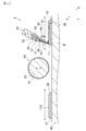
- FIG. 1 is a plan view showing a printing apparatus according to an embodiment of the present invention.
- FIG. 2 is a side sectional view showing a printing apparatus according to an embodiment of the present invention.
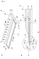
- FIG. 3 is a view showing a doctor blade device according to an embodiment of the present invention, FIG. 3 (a) is a perspective view, and FIG. 3 (b) is IIIb-IIIb in FIG. 3 (a). It is sectional drawing along a line.
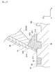
- FIG. 4 is a partially enlarged view of a portion IV in FIG.
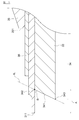
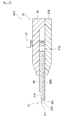
- FIG. 5 is a view showing a modification of the doctor blade device according to the embodiment of the present invention, and is an enlarged cross-sectional view of the tip of the doctor blade device.
- FIG. 1 is a plan view showing a printing apparatus according to an embodiment of the present invention.
- FIG. 2 is a side sectional view showing a printing apparatus according to an embodiment of the present invention.
- FIG. 3 is a view showing a doctor blade device according to an embodiment of the present invention,
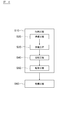
- FIG. 6 is a process diagram showing a method of manufacturing a wiring board according to an embodiment of the present invention.
- FIG. 7 is a flowchart showing a filling process, illustrating a method for manufacturing a wiring board according to an embodiment of the present invention.
- FIG. 8A is a diagram showing step S31 in FIG. 7, and
- FIG. 8B is a diagram showing step S32 in FIG.
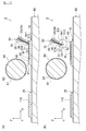
- FIG. 9 is a cross-sectional view for explaining the positional relationship between the doctor blade device and the intaglio according to one embodiment of the present invention.
- FIG. 10 is a cross-sectional view showing a state in which the doctor blade device according to the embodiment of the present invention slides on the intaglio.
- FIG. 11A is a diagram showing step S33 in FIG. 7, and FIG.
- FIG. 11B is a diagram showing step S34 in FIG.
- FIG. 12 is a partially enlarged view of the XII portion of FIG.
- FIG. 13A and FIG. 13B are views showing a method of manufacturing a wiring board according to an embodiment of the present invention, and are sectional views (part 1) for explaining a receiving process.
- FIG. 14 is a view showing the method for manufacturing a wiring board according to the embodiment of the present invention, and is a sectional view (No. 2) for explaining the receiving process.
- FIG. 15A and FIG. 15B are views showing a method for manufacturing a wiring board according to an embodiment of the present invention, and are sectional views (part 1) for explaining a transfer process.
- FIG. 16B are views showing a method of manufacturing a wiring board according to an embodiment of the present invention, and are sectional views (part 2) for explaining a transfer process.
- FIG. 17: is sectional drawing which shows the 1st modification of the doctor blade apparatus which concerns on one embodiment of this invention.
- FIG. 18 is a cross-sectional view showing a second modification of the doctor blade device according to one embodiment of the present invention.
- FIG. 1 is a plan view showing a printing apparatus according to an embodiment of the present invention
- FIG. 2 is a side sectional view showing a printing apparatus according to an embodiment of the present invention
- FIG. 3 is an embodiment of the present invention.
- FIG. 3 (a) is a perspective view
- FIG. 3 (b) is a cross-sectional view taken along line IIIb-IIIb of FIG. 3 (a)
- FIG. 4 is a diagram of FIG. 3 (b). It is the elements on larger scale of the IV section.
- the printing apparatus 1 in the present embodiment is an apparatus that manufactures the wiring board 100 (see FIG. 16B) by printing the conductive ink M on the base 110 by the gravure offset printing method.
- the wiring board 100 includes a base material 110 and a conductor layer 120.
- the base material 110 is a base material having insulation properties such as polyethylene terephthalate (PET), polyethylene naphthalate (PEN), polyimide (PI), and the like.
- the conductor layer 120 is formed by curing the conductive ink M transferred onto the substrate 110 by the printing apparatus 1.
- the conductive layer 120 includes a conductive material containing silver, copper, nickel, tin, bismuth, zinc, indium, palladium, graphite, and the like, an acrylic resin, a polyester resin, an epoxy resin, a vinyl resin, a urethane resin, a phenol resin, It is composed of a binder resin containing a polyimide resin or the like.
- the binder resin may be omitted from the material constituting the conductor layer 120.
- reference numeral 120 denotes a conductor layer after the conductive ink M is cured in a drying furnace 85 (described later).
- symbol (100) shows the wiring board which has the conductor layer 120 after having been effective in the drying furnace 85.
- the “wiring board 100” in the present embodiment corresponds to an example of the “wiring board” in the present invention
- the “base material 110” in the present embodiment corresponds to an example of the “base material” in the present invention.
- the conductive ink M of this embodiment is a material having a viscosity of 5 Pa ⁇ s to 50 Pa ⁇ s.
- Such a conductive ink M is configured by mixing various additives and a solvent in addition to the material constituting the conductor layer 120 described above.
- the solvent may be appropriately selected according to the type of binder resin to be used. For example, when a polyester resin is used as the binder resin, cyclohexyl acetate, butyl carbitole, 2-butoxyethyl acetate, isobutyl acetate are used.
- Examples thereof include alcohol, 2-ethylbutyl alcohol, ethyl carbitol, carbitol acetate, butyl carbitol acetate, butyl cellosolve, and isophorone.
- Examples of the additive include a curing agent, a coupling agent, and a corrosion inhibitor.
- the “conductive ink M” in the present embodiment corresponds to an example of the “conductive ink” in the present invention.
- the printing apparatus 1 includes a plate table 10, a base material table 20, a doctor blade device 30, a doctor mount 40, a dispenser 50, a transfer roller 60, a moving mechanism 71, 72, an apparatus frame 80, and a drying furnace 85.
- the plate table 10 is horizontally supported by the apparatus frame 80 and can be moved in parallel along the X direction by the moving mechanism 71.
- the plate table 10 has a holding surface 11 on which a flat intaglio 90 (gravure plate) is placed.
- the holding surface 11 is provided with a plurality of suction ports (not shown) that can hold the intaglio 90 by suction.
- the method for fixing the intaglio 90 to the plate table 10 is not particularly limited to this.
- the moving mechanism 71 for example, a ball screw mechanism using a motor can be exemplified.
- the “plate table 10” in the present embodiment corresponds to an example of the “base” in the present invention
- the “moving mechanism 71” in the present embodiment corresponds to an example of the “moving mechanism” in the present invention.
- the intaglio 90 of the present embodiment is a flat intaglio, and a concave pattern 92 is formed on the upper surface 91 by etching a metal layer made of copper or the like.
- the concave pattern 92 is a pattern corresponding to the conductor layer 120 of the wiring board 100.
- Such a concave pattern 92 may be, for example, a stripe pattern in which a plurality of fine lines are arranged in parallel to each other, or first and second fine lines (not shown) extending in different directions. It may be a mesh-like (mesh) pattern that intersects each other.
- the concave pattern has a mesh shape (mesh shape)
- a geometric pattern obtained by repeating various graphic units (for example, n-gons such as triangles and quadrangles, circles, ellipses, stars, etc.) It can be used as the shape of the unit mesh of the pattern.
- n-gons such as triangles and quadrangles, circles, ellipses, stars, etc.
- FIG. 1 only the concave pattern 92 of the intaglio plate 90 along the Y-axis direction is shown, but actually the concave pattern 92 is not only along the Y-axis direction but also in various directions. It is extended.
- the “intaglio 90” in the present embodiment corresponds to an example of the “intaglio” in the present invention
- the “concave pattern 92” in the present embodiment corresponds to an example of the “concave pattern” in the present invention.
- the substrate table 20 is horizontally supported by the apparatus frame 80, and can be translated along the X direction by the moving mechanism 72.
- the plate table 10 has a holding surface 21 on which a substrate 110 that is a printing medium is placed. Similar to the holding surface 11 of the plate table 10 described above, a plurality of suction ports are opened on the holding surface 21 so that the substrate 110 can be sucked and held.
- the method for fixing the substrate 110 to the substrate table 20 is not particularly limited to this.
- the moving mechanism 72 for example, a ball screw mechanism using a motor can be exemplified.
- a suction device (not shown) is juxtaposed in the vicinity of the standby position of the substrate table 20, and the substrate 110 placed on the substrate table 20 is transferred to the drying furnace 85 by the suction device.
- the drying furnace 85 include an IR (far infrared) drying furnace and a hot air drying furnace.
- the printed pattern (conductive ink M) transferred onto the substrate 110 is heated and cured by passing through the drying furnace 85, whereby the conductor layer 120 of the wiring board 100 is formed.
- the doctor blade device 30 is disposed above the intaglio plate 90 so as to face the intaglio plate 90. As shown in FIGS. 3 (a) and 3 (b), the doctor blade device 30 includes a blade body 31 and a blade holder 32. I have.
- the “doctor blade device 30” in the present embodiment corresponds to an example of the “doctor blade device” in the present invention.
- the blade body 31 is used to fill the concave pattern 92 formed on the upper surface 91 of the intaglio 90 with the conductive ink M and scrape the remaining conductive ink M on the upper surface 91 of the intaglio 90.
- the blade body 31 has a width corresponding to the intaglio 90 in the width direction (Y-axis direction).
- the blade body 31 is slidable in contact with the upper surface 91 of the intaglio 90 at the distal end portion 311 and is supported by the blade holder 32 on the proximal end portion 312 side.
- the blade body 31 includes a front surface 313 positioned forward in the traveling direction of the doctor blade device 30 and a rear surface 314 positioned opposite to the front surface 313 (that is, positioned rearward in the traveling direction of the blade device 30). ,have.
- the doctor blade device 30 is arranged in a posture for scraping off the conductive ink M on the intaglio plate 90 (see FIG. 2)
- the front surface 313 is in a posture to face downward so as to face the intaglio plate 90
- the rear surface 314 Takes a posture facing upward.
- the “blade body 31” in the present embodiment corresponds to an example of the “blade body” in the present invention
- the “front surface 313” in the present embodiment corresponds to an example of the “first main surface” in the present invention
- the “rear surface 314” in the embodiment corresponds to an example of the “second main surface” in the present invention.
- the blade holder 32 supports the blade body 31 from the base end 312 side of the blade body 31, and includes a first holder member 33, a second holder member 35 that faces the first holder member 33, and And a backing plate 36 and a fixture 37. A gap is formed between the first and second holder members 33 and 35.
- the first and second holder members 33 and 35 are disposed substantially parallel to each other.
- the blade body 31 is inserted between the first and second holder members 33 and 35, and the blade The blade body 31 can be supported by sandwiching the body 31 from the front and back (front and back).
- the second holder member 35 supports the blade main body 31 by pressing the rear surface 314 of the blade main body 31 toward the first holder member 33 through the contact plate 36.
- the abutting plate 36 is disposed so as to partially protrude from the distal end portion 351 of the second holder member 35 in the extending direction of the blade body 31, and reinforces the support of the blade body 31 by the second holder member 35. And a function of making the doctor pressure applied to the intaglio 90 uniform.
- the first holder member 33 supports the blade body 31 from the front surface 313 of the blade body 31.
- the first holder member 33 has a support portion 34 at a portion that contacts the front surface 313 of the blade body 31.
- the distal end portion 341 of the support portion 34 (first holder member 33) protrudes from the distal end portion 351 of the second holder member 35 in the extending direction of the blade body 31.
- the tip portion 341 of the support portion 34 is provided in the vicinity of the tip portion 311 of the blade body 31. Note that the tip end portion 341 of the support portion 34 does not protrude from the tip end portion 311 of the blade body 31, and as a result, the support portion 34 is attached to the blade body 31 to support the front surface 313 of the blade body 31. A step is formed by the tip 341 of the portion 34.
- the vicinity of the tip portion 311 of the blade body 31 means that the distance from the tip portion 311 of the blade body 31 to the first end portion 342 satisfies the following expression (6).
- the front end portion 341 of the present embodiment is disposed so as to be separated from the first end 342 that contacts the front surface 313 of the blade body 31 and the first end as well as from the intaglio 90 in a side sectional view.
- a second end portion 343, and the tip end portion 341 is a surface extending between the first and second end portions 342 and 343.
- the tip 341 is a surface that substantially coincides with the virtual straight line IL passing through the first and second ends 342 and 343 in a side sectional view.
- the distance between the first and second end portions 342 and 343 is preferably 1 mm to 10 mm.
- the distance between the first and second end portions 342 and 343 is preferably not less than 0.5 times and not more than twice a distance A described later.
- it is preferable that the 2nd edge part 343 does not protrude from the surface on the opposite side to the side facing the blade main body 31 of the 1st holder member 33 in side surface sectional view.
- the part corresponded to the 2nd edge part 343 is made into the square shape, it is not limited to this in particular, You may be chamfered by R shape.
- the R shape is a substantially arc-shaped continuous curve.
- the end of the R shape on the side away from the blade body 31 corresponds to the second end portion 343.
- the front surface 313 of the blade body 31 and the tip portion 341 (tip surface) extend in different directions, so that the front surface 313 and the tip portion 341 (tip surface) are not positioned substantially on the same plane. ing.
- the following expression (5) is preferably satisfied. 30 ° ⁇ B ⁇ 150 ° (5)
- B is an angle formed by the front surface 313 and the virtual straight line IL.
- FIG. 5 is a view showing a modification of the doctor blade device according to the embodiment of the present invention, and is an enlarged sectional view of the tip of the doctor blade device.
- the tip 341 of the present embodiment is inclined so as to approach the tip 311 of the blade body 31 as it moves away from the front surface 313 of the blade body 31 in the extending direction of the blade body 31. It may be an inclined surface.
- the front end portion 341 of the support portion 34 is downwardly facing the intaglio plate 90. (See FIG. 2).
- the doctor blade device 30 slides on the intaglio plate 90, the conductive ink scraped by the blade body 31 in a region surrounded by the front surface 313, the tip portion 341, and the upper surface 91 of the intaglio plate 90. M is stored.
- the portion between the first and second end portions 342 and 343 can contact the conductive ink M.
- the tip 341 can hold the conductive ink M.
- the first and second holder members 33 and 35 are connected by a fixture 37 as shown in FIGS. 3 (a) and 3 (b).
- the fixing tool 37 is for preventing the blade body 31 from falling off the blade holder 32, and includes fastening bolts arranged at substantially equal intervals along the width direction of the blade body 31.
- the blade main body 31 can be fixed to the blade holder 32 by tightening the fastening bolt that is the fixing tool 37.
- the “blade holder 32” in the present embodiment corresponds to an example of the “blade holder” in the present invention
- the “first holder member 33” in the present embodiment corresponds to an example of the “first support portion” in the present invention.
- the “second holder member 35” in the present embodiment corresponds to an example of the “second support portion” in the present invention
- the “support portion 34” in the present embodiment corresponds to the “plate-shaped portion” in the present invention.
- the “tip portion 341” in the present embodiment corresponds to an example of the “ink holding portion” in the present invention
- the “virtual straight line IL” in the present embodiment corresponds to an example of the “virtual straight line” in the present invention.
- the doctor gantry 40 is a gantry on which the doctor blade device 30 can be attached and detached.
- the doctor mount 40 has a mechanism that can move up and down, and can approach or leave the intaglio 90 held by the plate table 10.
- a mechanism for moving the doctor mount 40 up and down for example, a rack and pinion gear mechanism using a motor or the like can be exemplified.
- the doctor table 40 is lowered, and the plate table 10 is moved in the X direction by the moving mechanism 71 in a state in which the tip 311 of the blade body 31 is in contact with the upper surface 91 of the intaglio plate 90.
- the upper conductive ink M is coated and scraped off.
- the plate table 10 is horizontally moved by the moving mechanism 71.
- the doctor table 40 and the plate table 10 are not particularly limited to the above as long as the doctor table 40 and the plate table 10 are relatively movable.
- the doctor frame may be moved horizontally with respect to the plate table by the moving mechanism, or a moving mechanism is provided for each of the doctor frame and the plate table, and under the synchronous drive of these moving mechanisms, The doctor mount and the plate table may be moved relative to each other.
- the dispenser 50 is a device that supplies the conductive ink M onto the intaglio 90 and is provided in the vicinity of the doctor blade device 30.
- the dispenser 50 is movable along the Z direction together with the doctor blade device 30.
- the doctor blade device 30 and the dispenser 50 are operated under synchronous drive, but may be operated independently. In this case, the doctor blade device 30 may be operated after the dispenser 50 is operated.
- the “dispenser 50” in the present embodiment corresponds to an example of the “supply device” in the present invention.
- the transfer roller 60 includes a blanket cylinder 61 and a blanket 62.
- the blanket cylinder 61 is supported so as to be rotatable about its central axis.
- the blanket 62 is made of, for example, silicone rubber or the like, and is wound around the outer periphery of the blanket cylinder 61 via an adhesive layer (not shown).
- the transfer roller 60 can be driven to rotate by a motor (not shown).
- the transfer roller 60 can be moved up and down in the Z direction by, for example, a rack and pinion gear mechanism (not shown). In this case, the transfer roller 60 is lowered so that it can come into contact with the intaglio 90 placed on the plate table 10 or the substrate 110 placed on the substrate table 20.
- the “transfer roller 60” in the present embodiment corresponds to an example of the “transfer body” in the present invention.
- FIG. 6 is a process diagram showing a method of manufacturing a wiring board according to an embodiment of the present invention.
- the method for manufacturing the wiring board 100 of the present embodiment includes a printing step S10 and a drying step S60 as shown in FIG.
- the printing step S10 will be described in detail with reference to FIGS.
- the “printing step S10” in the present embodiment corresponds to an example of the “printing step” in the present invention
- the “drying step S60” in the present embodiment corresponds to an example of the “drying step” in the present invention.
- FIG. 7 is a diagram showing a method for manufacturing a wiring board according to an embodiment of the present invention, and is a flowchart showing a filling process
- FIG. 8A, FIG. 8B, FIG. 11A, and FIG. (B) is a diagram showing each step of FIG. 6
- FIG. 9 is a sectional view for explaining the positional relationship between the doctor blade device and the intaglio according to one embodiment of the present invention
- FIG. Sectional drawing which shows the state which the doctor blade apparatus which concerns on embodiment slides on an intaglio
- FIG. 12 is the elements on larger scale of the XII part of FIG.11 (b), FIG.13 (a), FIG.13 (b), FIG.
- FIG. 14 is a view showing a method for manufacturing a wiring board according to an embodiment of the present invention, and is a cross-sectional view for explaining a receiving process
- FIG. 16B are diagrams showing a method of manufacturing a wiring board according to an embodiment of the present invention. It is a cross-sectional view for the explanation.
- the printing process S10 of the present embodiment includes a preparation process S20, a filling process S30, a receiving process S40, and a transfer process S50.
- Preparation step S20 in the present embodiment corresponds to an example of “first step” in the present invention
- filling step S30 in the present embodiment corresponds to an example of “second step” in the present invention.
- accepting step S40 in the present embodiment corresponds to an example of the “third step” in the present invention
- the “transfer step S50” in the present embodiment corresponds to an example of the “fourth step” in the present invention.
- the doctor blade device 30 of the present embodiment is prepared.
- the filling step S30 as shown in FIG. 8A, first, the doctor blade device 30 that has been waiting at a predetermined standby position is lowered (moved in the ⁇ Z direction) (step S31 in FIG. 7), and the blade The front end portion 311 of the main body 31 is brought into contact with the upper surface 91 of the intaglio 90.
- the doctor blade device 30 When the doctor blade device 30 is arranged in a posture to scrape the conductive ink M on the intaglio plate 90, the doctor blade device 30 is inclined by a predetermined angle with respect to the upper surface 91 of the intaglio plate 90 as shown in FIG. Become posture. In this case, the doctor blade device 30 (specifically, the blade body 31) is held so that the following expression (7) is established.
- C is an angle formed by a direction substantially perpendicular to the intaglio plate 90 (Z direction) and the extending direction of the tip 341.
- counterclockwise (counterclockwise) is the positive direction
- counterclockwise (clockwise) is the negative direction around the contact point O between the blade body 31 and the upper surface 91 of the intaglio 90. .
- the doctor blade device 30 is in a posture inclined by a predetermined angle with respect to the upper surface 91 of the intaglio 90 so that the distal end portion 341 of the support portion 34 is perpendicular to the front surface 313 of the blade body 31. Even the surface extending in any direction is inclined so as to approach the intaglio 90 as the tip 341 moves away from the front surface 313.
- the doctor blade apparatus 30 is arrange
- D is a distance from the intaglio to the second end in a direction perpendicular to the intaglio.
- the conductive ink M is supplied onto the intaglio 90 from a dispenser (not shown). Then, with the doctor blade device 30 in contact with the intaglio 90, the plate table 10 is moved along the -X direction in the figure (step S32 in FIG. 7). The conductive ink may be supplied before the doctor blade device is lowered (that is, step S31).
- the doctor blade device 30 (specifically, the tip 311 of the blade body 31) slides on the intaglio plate 90, thereby scraping off the conductive ink M applied on the upper surface 91 of the intaglio plate 90, and the concave pattern. 92 is filled with the conductive ink M.
- the conductive ink M scraped off in front of the blade body 31 (traveling direction side) is stored.
- the stored conductive ink M gradually increases, so that the conductive ink M rises upward, and the tip of the support portion 34 disposed in the vicinity of the tip portion 311 of the blade body 31. It contacts the part 341.
- the front end portion 341 can hold the conductive ink M by contacting the conductive ink M present on the intaglio 90.
- the plate table 10 is stopped (step S33 in FIG. 7).
- the conductive ink M of the present embodiment is located above the conductive ink M scraped to the front (traveling direction side) of the blade body 31 even after the filling of the conductive ink M into the concave pattern 92 is completed. (Ie, the state in which the conductive ink M is in contact with the tip 341 of the support portion 34) is maintained.
- the doctor blade device 30 is raised (moved in the + Z direction), and the doctor blade device 30 is retracted from the intaglio 90 (step S34 in FIG. 7).
- the conductive ink M hangs in an icicle shape from the tip of the doctor blade device 30 due to its own weight.
- the front surface 313 and the tip 341 hold the conductive ink M that hangs down.
- the icicle-shaped conductive ink (hereinafter referred to as “icicle”) has an outer shape in which the stress due to its own weight is substantially uniform in the Z direction (ie, gradually toward the tip of the conductive ink in a side sectional view).
- the tip position in the X direction is substantially equal to the center of the surface that holds the conductive ink (hereinafter referred to as “holding surface”).
- the front surface of the blade body in contact with the conductive ink is a holding surface (having a width W1 in the X direction).
- the front surface 313 and the front end portion 341 that are in contact with the conductive ink M serve as a holding surface (having a width W2 in the X direction).
- the surface that holds the conductive ink M is expanded in a direction away from the tip portion 311 (expanded by a length W3 in the drawing).
- the icicle tip held by the front surface 313 and the tip portion 341 moves in a direction away from the tip portion 311 as compared with the conventional case.
- the icicle moves forward by a length W4 in the drawing.
- the conventional icicle-shaped conductive ink is represented by a broken line
- the icicle-shaped conductive ink in the present embodiment is represented by a solid line.
- the component force along the extending direction of the front end portion 341 in the dead weight of the conductive ink M acts in the direction of moving the icicle away from the front surface 313 (the front end portion 311 of the blade body 31). Suppresses the flow toward 311.
- the process proceeds to a receiving step S40.
- the receiving step S40 first, as shown in FIG. 13A, the plate table 10 is moved along the ⁇ X direction by the moving mechanism 71 and disposed below the transfer roller 60. Then, the transfer roller 60 is moved downward from the standby position, and the transfer roller 60 is pressed against the intaglio 90 placed on the plate table 10. Then, as shown in FIG. 13B, the transfer roller 60 is rotated clockwise (clockwise), and the plate table 10 is moved along the ⁇ X direction by the moving mechanism 71.
- the transfer roller 60 rolls on the intaglio plate 90, and the conductive ink M filled in the concave pattern 92 of the intaglio plate 90 is received by the blanket 62 of the transfer roller 60, and a conductor layer is formed on the blanket 62.
- a print pattern corresponding to 120 is held.
- the transfer roller 60 is raised and retracted to the standby position, and the plate table 10 is moved along the X direction from below the transfer roller 60 to retract to the standby position.
- the “print pattern corresponding to the conductor layer 120” in the present embodiment corresponds to an example of the “print pattern” in the present invention.
- the process proceeds to the transfer step S50.
- the transfer step S50 first, as shown in FIG. 15A, the substrate table 20 is moved along the + X direction by the moving mechanism 72 and disposed below the transfer roller 60. Then, as shown in FIG. 15B, the transfer roller 60 is moved downward from the standby position, and the transfer roller 60 is pressed against the base material 110 placed on the base material table 20. Then, as shown in FIG. 16A, the transfer roller is rotated clockwise (clockwise), and the substrate table 20 is moved along the ⁇ X direction by the moving mechanism 72.
- the transfer roller 60 rolls on the substrate 110, and the print pattern corresponding to the conductor layer 120 held on the blanket 62 of the transfer roller 60 is transferred to the substrate 110. Then, as shown in FIG. 16B, the transfer roller 60 is raised and retracted to the standby position, and the substrate table 20 is moved along the ⁇ X direction from below the transfer roller 60 to retract to the standby position.
- the process proceeds to the drying process S60.
- the conductor layer 120 is formed on the substrate 110 by heating and curing the print pattern using the drying furnace 85 (see FIG. 1). Thereby, the wiring board 100 can be obtained.
- the printing apparatus 1 of the present embodiment is used when a plurality of wiring boards 100 are continuously manufactured, and shifts to the transfer step S50 (specifically, the plate table 10 is moved to a standby position).
- the transfer step S50 specifically, the plate table 10 is moved to a standby position.
- a filling step S30 is started to manufacture the next wiring board 100 (see FIGS. 15B, 16A, and 16B). That is, after the doctor blade device 30 is moved to the standby position, the doctor blade device 30 is lowered and the tip 311 of the blade body 31 is brought into contact with the intaglio plate 90.
- icicles hang down from the vicinity of the tip of the doctor blade device even when the doctor blade device is waiting at the standby position.
- this doctor blade device is pressed against the intaglio, the icicles push and spread on the intaglio, and there is a possibility that a reverse side may occur.
- the front end portion 341 of the first holder member 33 (specifically, the support portion 34) is provided in front of the front surface 313 of the blade body 31, and the front end portion 341 is provided with conductive ink.
- the doctor blade device 30, the printing device 1, the printing method, and the method for manufacturing the wiring board 100 according to the present embodiment have the following effects.
- the tip portion 341 of the first holder member 33 (specifically, the support portion 34) is provided in front of the front surface 313 of the blade body 31 in the vicinity of the tip portion 311 of the blade body 31.
- Conductive ink M is held at the tip 341.
- the surface that holds the conductive ink M is expanded forward according to the front end portion 341, so that the hanging conductive ink M moves forward, thereby suppressing the occurrence of printing defects due to the backside. it can.
- the tip end portion 341 can be more reliably brought into contact with the conductive ink M, and therefore the occurrence of backside is further suppressed.
- A is the distance from the tip 311 of the blade body 31 to the first end 342 in the extending direction of the blade body 31.
- the portion between the first and second end portions 342 and 343 of the leading end portion 341 is disposed so as to intentionally contact the conductive ink M present on the intaglio 90.
- the tip portion 341 By holding the conductive ink M by the tip portion 341, it is possible to suppress the occurrence of printing failure due to the back of the conductive ink M hanging down in an icicle shape.
- the distance between the first and second end portions 342 and 343 is set to 1 mm to 10 mm, it is possible to further suppress the occurrence of printing defects due to the back side of the conductive ink M. That is, if the distance between the first and second end portions 342 and 343 is less than 1 mm, the conductive ink M cannot be sufficiently held by the tip portion 341, and printing failure due to the back side of the conductive ink M is caused. It is difficult to obtain a sufficient suppression effect. On the other hand, if the distance between the first and second end portions 342 and 343 exceeds 10 mm, the area for storing the conductive ink becomes too large, and the conductive ink is sufficiently stored in front of the doctor blade device. Not.
- the doctor blade device When the doctor blade device is raised in this state, the conductive ink is separated and hangs down on the tip side and the blade body side, and it is difficult to sufficiently obtain the effect of suppressing the occurrence of printing defects due to the back of the conductive ink.
- the width of the surface that holds the ink in the tip portion 341 it is possible to suppress the occurrence of printing defects due to the back side of the conductive ink M.
- the distance between the first and second end portions 342 and 343 is not less than 0.5 times and not more than twice the distance A, so that the conductive ink M is turned around by the same action as described above. The occurrence of printing defects can be further suppressed.
- the second end portion 343 does not protrude from the surface of the first holder member 33 opposite to the side opposite to the blade body 31 in the side sectional view. It is possible to further suppress the occurrence of printing defects due to the back of the conductive ink M.
- the tip 341 can be easily exposed to the stored conductive ink M. Therefore, the tip 341 and the stored conductive ink M Can be reliably contacted. 30 ° ⁇ B ⁇ 150 ° (11)
- B is an angle formed by the front surface 313 and the virtual straight line IL.
- the tip surface 341 has an inclined surface that inclines so as to approach the tip portion 311 as it moves away from the front surface 313 of the blade body 31 in the extending direction of the blade body 31.
- the component force along the extending direction of the front end portion 341 of the self weight acts on the icicle in a direction away from the front surface 313 (the front end portion 311 of the blade body 31).
- an icicle tries to flow down toward the front-end
- FIG. As a result, the icicle hanging down from the tip of the doctor blade device 30 moves forward, and as a result, it is possible to suppress the occurrence of printing defects due to the reverse side.
- the component force along the extending direction of the tip portion 341 of the icicle's own weight is applied to the icicle. It is reliably applied in a direction away from the part 311. Thereby, it can suppress that an icicle tries to flow down toward the front-end
- C is an angle formed by the direction substantially perpendicular to the intaglio 90 and the extending direction of the virtual straight line IL.
- the tip portion 341 can be more reliably brought into contact with the conductive ink M, so that the occurrence of backside is further suppressed.
- D is the distance from the intaglio 90 to the second end 343 in the direction perpendicular to the intaglio 90.
- FIG. 17 is a cross-sectional view showing a first modification of the doctor blade device according to one embodiment of the present invention
- FIG. 18 is a cross-sectional view showing a second modification of the doctor blade device according to one embodiment of the present invention. It is.
- the tip portion 341 of the first holder member 33 is configured as an ink holding portion, but is not particularly limited thereto, and is attached to the front surface 313 of the blade body 31 as shown in FIG. Then, the plate-like member 38 may be attached to the front surface 313. If the blade body 31 is attached to the front surface 313 of the blade body 31, the plate-like member 38B is sandwiched between the first and second boulder members 33 and 35 together with the blade body 31 and the contact plate 36 as shown in FIG. May be held.
- the tip portion 381 of the plate-like member 38 is positioned in the vicinity of the tip portion 311 of the blade body 31, the tip portion 381 and the conductive ink M are in contact with each other, and the same effects as in the above-described embodiment. Can be played.
- the “plate member 38” in the present embodiment corresponds to an example of the “plate portion” in the present invention
- the “tip portion 381” in the present embodiment corresponds to an example of the “ink holding portion” in the present invention.
- the transfer roller 60 is used, and the conductive ink M is received by the transfer roller 60 from the intaglio plate 90 (that is, the receiving step S40), and the transfer roller 60 that receives the conductive ink M is used as the base.
- the transfer to the material 110 (that is, the transfer step S50) is not particularly limited to the above.
- the conductive ink may be transferred directly from the intaglio to the substrate.
- the printing apparatus 1 of the present embodiment has one doctor blade apparatus 30, the printing apparatus 1 is not particularly limited thereto, and may have two doctor blade apparatuses.
- one doctor blade device is used as a doctor blade device for coating that fills the concave pattern of the intaglio plate with conductive ink
- the other doctor blade device is a conductive material remaining on the upper surface of the intaglio plate.
- the present invention can be applied to both the doctor blade device for coating and the doctor blade device for scraping.
Landscapes
- Engineering & Computer Science (AREA)
- Mechanical Engineering (AREA)
- Manufacturing & Machinery (AREA)
- Microelectronics & Electronic Packaging (AREA)
- Printing Methods (AREA)
- Manufacturing Of Printed Wiring (AREA)
- Rotary Presses (AREA)
Abstract
平板状の凹版(90)上を摺動するドクターブレード装置(30)は、ドクターブレード装置(30)の進行方向において、前方に位置する前面(313)を有するブレード本体(31)と、ブレード本体(31)の先端部(311)近傍において、前面(313)よりも前方に設けられた先端部(341)と、を備え、先端部(341)は、前面(313)と接触する第1の端部(342)と、凹版(90)と離間するように配置される第2の端部(343)と、を有し、先端部(341)は、第1の端部(342)と第2の端部(343)との間の部分が凹版(90)上に存在する導電性インク(M)と接触することで導電性インク(M)を保持可能であり、下記(1)式を満たす。 1mm≦A≦5mm・・・(1) 但し、上記(1)式において、Aはブレード本体(31)の延在方向におけるブレード本体(31)の先端部(311)から第1の端部(342)までの距離である。
Description
本発明は、ドクターブレード装置、印刷装置、印刷方法、及び配線基板の製造方法に関するものである。
文献の参照による組み込みが認められる指定国については、2015年3月17日に日本国に出願された特願2015-052934号に記載された内容を参照により本明細書に組み込み、本明細書の記載の一部とする。
文献の参照による組み込みが認められる指定国については、2015年3月17日に日本国に出願された特願2015-052934号に記載された内容を参照により本明細書に組み込み、本明細書の記載の一部とする。
凹版上に対向したドクターブレードを備え、当該ドクターブレードの凹版上の摺動により、凹版上の余分なインキを掻き取ると共に、当該凹版にインキを充填する技術が知られている。(たとえば、特許文献1参照)。
また、ドクターブレードとして、円筒状の版に用いられ、その前方にインクが飛び散るのを防止するインクガード(インク返し)を備えるものが知られている(たとえば、特許文献2及び3参照)。
平板状の凹版では、上記技術のようにドクターブレードにより余分なインキを掻き取った後、当該凹版に充填されたインキを被転写物に転写するため、当該ドクターブレードを凹版から離反させる。この際、インキがドクターブレードの先端に接触していると、当該インキがドクターブレードの先端からつらら状に垂れ下がる場合がある。このため、ドクターブレードを凹版に再度押し付けた際に、当該ドクターブレードの先端から垂れ下がったつらら状のインキも押し広がって、ドクターブレードの後方に回り込み(いわゆる、裏回りが生じる。)、印刷不良を発生させるおそれがあるという問題がある。
本発明が解決しようとする課題は、印刷不良の発生を抑制できるドクターブレード装置、印刷装置、印刷方法、及び配線基板の製造方法を提供することである。
[1]本発明に係るドクターブレード装置は、平板状の凹版上を摺動し、前記ドクターブレード装置の進行方向において、前方に位置する第1の主面を有するブレード本体と、前記ブレード本体の先端近傍において、前記第1の主面よりも前方に設けられたインク保持部と、を備え、前記インク保持部は、前記第1の主面と接触する第1の端部と、前記凹版と離間するように配置される第2の端部と、を有し、前記インク保持部は、前記第1の端部と前記第2の端部との間の部分が前記凹版上に存在する導電性インクと接触することで前記導電性インクを保持可能であり、下記(1)式を満たす。
1mm≦A≦5mm・・・(1)
但し、上記(1)式において、Aは前記ブレード本体の延在方向における前記ブレード本体の先端から前記第1の端部までの距離である。
1mm≦A≦5mm・・・(1)
但し、上記(1)式において、Aは前記ブレード本体の延在方向における前記ブレード本体の先端から前記第1の端部までの距離である。
[2]上記発明において、下記(2)式を満たしていてもよい。
30°≦B≦150°・・・(2)
但し、上記(2)式において、Bは前記第1の主面と、前記インク保持部の前記第1の端部と前記第2の端部とを通過する仮想直線と、のなす角である。
30°≦B≦150°・・・(2)
但し、上記(2)式において、Bは前記第1の主面と、前記インク保持部の前記第1の端部と前記第2の端部とを通過する仮想直線と、のなす角である。
[3]上記発明において、前記インク保持部は、前記第1の端部と前記第2の端部との間を延在し、前記ブレード本体の延在方向において前記第1の主面から離れるに従い前記ブレード本体の先端に接近するように傾斜する傾斜面を有していてもよい。
[4]上記発明において、前記ブレード本体の前記第1の主面に装着される板状部分をさらに備え、前記板状部分は、前記板状部分の先端が前記ブレード本体の先端近傍に位置するように設けられ、前記板状部分の先端は、前記インク保持部を構成してもよい。
[5]上記発明において、前記ブレード本体を保持するブレードホルダをさらに備え、前記ブレードホルダは、前記第1の主面を支持する第1の支持部と、前記ブレード本体において前記第1の主面の反対側の第2の主面を支持する第2の支持部と、を有し、前記第1の支持部は、前記ブレード本体の延在方向において、前記第2の支持部よりも突出し、前記第1の支持部の先端は、前記インク保持部を構成してもよい。
[6]本発明に係る印刷装置は、上記ドクターブレード装置と、前記凹版を支持する基台と、前記凹版に前記導電性インクを供給する供給装置と、前記基台と前記ドクターブレード装置とを相対移動させる移動機構と、を備える。
[7]本発明に係る印刷方法は、平板状の凹版を用いて導電性インクを印刷する方法であり、上記ドクターブレード装置を準備する第1の工程と、前記凹版と前記ドクターブレード装置とを相対的に摺動させ、前記ブレード本体により前記凹版の凹パターンに前記導電性インクを充填する第2の工程と、を備え、前記第2の工程において、前記ブレード本体により掻き取られた前記導電性インクが、前記インク保持部の少なくとも一部と接触する。
[8]上記発明において、下記(3)式を満たしていてもよい。
|C|≦90°・・・(3)
但し、上記(3)式において、Cは前記凹版に対して実質的に垂直な方向と、前記インク保持部の前記第1の端部と前記第2の端部とを通過する仮想直線の延在方向と、のなす角である。
|C|≦90°・・・(3)
但し、上記(3)式において、Cは前記凹版に対して実質的に垂直な方向と、前記インク保持部の前記第1の端部と前記第2の端部とを通過する仮想直線の延在方向と、のなす角である。
[9]上記発明において、下記(4)式を満たしていてもよい。
0.1mm≦D≦5mm・・・(4)
但し、上記(4)式において、Dは前記凹版に対して垂直な方向における前記凹版から前記第2の端部までの距離である。
0.1mm≦D≦5mm・・・(4)
但し、上記(4)式において、Dは前記凹版に対して垂直な方向における前記凹版から前記第2の端部までの距離である。
[10]上記発明において、前記第2の工程の後に、前記凹版から転写体に前記導電性インクを受理する第3の工程と、前記転写体から基板に前記導電性インクを転写する第4の工程と、をさらに備えていてもよい。
[11]本発明に係る配線基板の製造方法は、上記印刷方法により基板上に印刷パターンを形成する印刷工程と、前記印刷パターンを乾燥させる乾燥工程と、を備える。
本発明によれば、ドクターブレード装置の第1の主面よりも前方にインク保持部を設け、当該インク保持部に導電性インクを保持させる。これにより、ドクターブレード装置から垂れ下がる導電性インクが前方に移動するので、裏回りによる印刷不良の発生を抑制できる。
以下、本発明の実施形態を図面に基づいて説明する。なお、以下の説明で用いる図は、本発明の特徴をわかりやすくするために、便宜上、要部となる部分を拡大して示している場合があり、各構成要素の寸法比率などが実際と同じであるとは限らない。
図1は本発明の一実施の形態に係る印刷装置を示す平面図、図2は本発明の一実施の形態に係る印刷装置を示す側面断面図、図3は本発明の一実施の形態に係るドクターブレード装置を示す図であり、図3(a)は斜視図、図3(b)は図3(a)のIIIb-IIIb線に沿った断面図、図4は図3(b)のIV部の部分拡大図である。
本実施形態における印刷装置1は、グラビアオフセット印刷法によって基材110に導電性インクMを印刷することにより、配線基板100(図16(b)参照)を製造する装置である。
配線基板100は、基材110と、導体層120と、を備えている。基材110は、ポリエチレンテレフタレート(PET)、ポリエチレンナフタレート(PEN)、ポリイミド(PI)等の絶縁性を有する基材である。導体層120は、印刷装置1によって基材110上に転写された導電性インクMを硬化させることにより形成されている。この導体層120は、銀や銅、ニッケル、スズ、ビスマス、亜鉛、インジウム、パラジウム、グラファイト等を含有する導電性材料と、アクリル樹脂、ポリエステル樹脂、エポキシ樹脂、ビニル樹脂、ウレタン樹脂、フェノール樹脂、ポリイミド樹脂等を含有するバインダ樹脂等から構成されている。なお、導体層120を構成する材料からバインダ樹脂を省略してもよい。
なお、図16(b)において、符号(120)は、導電性インクMを乾燥炉85(後述)で硬化させた後の導体層を示す。また、同図において、符号(100)は、乾燥炉85で効果した後の導体層120を有する配線基板を示す。本実施形態における「配線基板100」が本発明における「配線基板」の一例に相当し、本実施形態における「基材110」が本発明における「基材」の一例に相当する。
なお、本実施形態の導電性インクMは、5Pa・s~50Pa・sの粘度を有している材料とされている。このような導電性インクMは、上述の導体層120を構成する材料に加えて、各種添加剤および溶剤を混合して構成されている。溶剤としては、用いるバインダ樹脂の種類に応じて適宜、選択すればよいが、たとえば、バインダ樹脂としてポリエステル系樹脂を用いる場合には、酢酸シクロヘキシル、酢酸ブチルカルビトーレ、酢酸-2-ブトキシエチル、イソブチルアルコール、2-エチルブチルアルコール、エチルカルビトール、カルビトールアセテート、ブチルカルビトールアセテート、ブチルセロソルブ、イソホロンなどが挙げられる。添加剤としては、硬化剤、カップリング剤、腐食抑制剤などを例示することができる。本実施形態における「導電性インクM」が本発明における「導電性インク」の一例に相当する。
印刷装置1は、図1及び図2に示すように、版テーブル10と、基材テーブル20と、ドクターブレード装置30と、ドクター架台40と、ディスペンサ50と、転写ローラ60と、移動機構71,72と、装置フレーム80と、乾燥炉85と、を備えている。
版テーブル10は、装置フレーム80に水平に支持されており、移動機構71によりX方向に沿って平行移動が可能となっている。この版テーブル10は、平板状の凹版90(グラビア版)が載置されている保持面11を有している。この保持面11は、特に図示しない複数の吸引口が開口しており、凹版90を吸着保持することが可能となっている。なお、版テーブル10に凹版90を固定する方法は、特にこれに限定されない。因みに、移動機構71としては、たとえば、モータを用いたボールねじ機構等を例示することができる。本実施形態における「版テーブル10」が本発明における「基台」の一例に相当し、本実施形態における「移動機構71」が本発明における「移動機構」の一例に相当する。
本実施形態の凹版90は、平板状とされた凹版であり、その上面91に銅等からなる金属層をエッチング等することで凹パターン92が形成されている。この凹パターン92は、配線基板100の導体層120に対応したパターンとされている。このような凹パターン92としては、たとえば、相互に平行に複数の細線を配列するストライプ状のパターンであってもよいし、異なる方向に延在する第1及び第2の細線(不図示)を相互に交差させてなる網目状(メッシュ状)のパターンであってもよい。凹パターンを網目状(メッシュ状)とする場合は、種々の図形単位(たとえば、三角形、四角形等のn角形や、円、楕円、星型等)を繰り返して得られる幾何学模様を、当該凹パターンの単位網目の形状として用いることができる。なお、図1に示す例では、凹版90の凹パターン92としてY軸方向に沿ったものしか図示していないが、実際にはこの凹パターン92はY軸方向のみならず多種多様な方向に沿って延在している。本実施形態における「凹版90」が本発明における「凹版」の一例に相当し、本実施形態における「凹パターン92」が本発明における「凹パターン」の一例に相当する。
基材テーブル20は、装置フレーム80に水平に支持されており、移動機構72によりX方向に沿って平行移動が可能となっている。この版テーブル10は、被印刷体である基材110が載置される保持面21を有している。上述の版テーブル10の保持面11と同様に、この保持面21にも複数の吸引口が開口しており、基材110を吸着保持することが可能となっている。なお、基材テーブル20に基材110を固定する方法は、特にこれに限定されない。因みに、移動機構72としては、たとえば、モータを用いたボールねじ機構等を例示することができる。
この基材テーブル20の待機位置の近傍には、吸着装置(不図示)が並設されており、当該吸着装置により基材テーブル20上に載置された基材110が乾燥炉85に移送される。なお、乾燥炉85としては、たとえば、IR(遠赤外線)乾燥炉や熱風乾燥炉等を例示することができる。基材110上に転写された印刷パターン(導電性インクM)は、この乾燥炉85を通過することで加熱され、硬化することで、配線基板100の導体層120が形成される。
ドクターブレード装置30は、凹版90の上方に当該凹版90と対向して配置されており、図3(a)及び図3(b)に示すように、ブレード本体31と、ブレードホルダ32と、を備えている。本実施形態における「ドクターブレード装置30」が本発明における「ドクターブレード装置」の一例に相当する。
ブレード本体31は、凹版90の上面91に形成された凹パターン92に導電性インクMを充填し、当該凹版90の上面91上に残余する導電性インクMを掻き取るために用いられる。このブレード本体31は、幅方向(Y軸方向)において、凹版90に対応した幅を有している。このブレード本体31は、先端部311において、凹版90の上面91と摺接可能となっており、基端部312側において、ブレードホルダ32により支持されている。
また、ブレード本体31は、ドクターブレード装置30の進行方向において前方に位置する前面313と、当該前面313と反対側に位置する(すなわち、ブレード装置30の進行方向において後方に位置する)後面314と、を有している。なお、本実施形態では、凹版90上の導電性インクMを掻き取る姿勢でドクターブレード装置30を配置すると(図2参照)、前面313は凹版90に臨むように下方を向く姿勢となり、後面314は上方を向く姿勢となる。
本実施形態における「ブレード本体31」が本発明における「ブレード本体」の一例に相当し、本実施形態における「前面313」が本発明における「第1の主面」の一例に相当し、本実施形態における「後面314」が本発明における「第2の主面」の一例に相当する。
ブレードホルダ32は、ブレード本体31の基端部312側から当該ブレード本体31を支持しており、第1のホルダ部材33と、当該第1のホルダ部材33に対向する第2のホルダ部材35と、当て板36と、固定具37と、を有している。第1及び第2のホルダ部材33,35の間には、間隙が形成されている。また、第1及び第2のホルダ部材33,35は、相互に略平行に配設されており、この第1及び第2のホルダ部材33,35の間にブレード本体31を挿入し、当該ブレード本体31を表裏(前後)から挟み込むことで当該ブレード本体31を支持することができるようになっている。
第2のホルダ部材35は、当て板36を介してブレード本体31の後面314を第1のホルダ部材33側に向かって押圧することで当該ブレード本体31を支持している。当て板36は、ブレード本体31の延在方向において、第2のホルダ部材35の先端部351よりも一部が突出して配置されており、第2のホルダ部材35によるブレード本体31の支持を補強する機能や、凹版90に印加するドクター圧を均一にする機能を有している。
一方、第1のホルダ部材33は、ブレード本体31の前面313から当該ブレード本体31を支持している。この第1のホルダ部材33は、ブレード本体31の前面313と当接する部分に支持部34を有する。この支持部34(第1のホルダ部材33)の先端部341は、ブレード本体31の延在方向において、第2のホルダ部材35の先端部351よりも突出している。
また、本実施形態では、この支持部34の先端部341がブレード本体31の先端部311の近傍に位置するように設けられている。なお、支持部34の先端部341は、ブレード本体31の先端部311よりは突出しておらず、結果として、ブレード本体31に支持部34を添わせることで、当該ブレード本体31の前面313と支持部34の先端部341によって段差が形成される。本実施形態において、ブレード本体31の先端部311の近傍とは、当該ブレード本体31の先端部311から第1の端部342までの距離が、後述の(6)式を満たすことを意味する。
本実施形態の先端部341は、側面断面視において、ブレード本体31の前面313と接触する第1の端部342と、当該第1の端部と離間すると共に凹版90とも離間するように配置された第2の端部343と、を有しており、当該先端部341は、この第1及び第2の端部342,343間を延在する面となる。なお、本実施形態では、この先端部341は、側面断面視において、第1及び第2の端部342,343を通過する仮想直線ILと実質的に一致する面となる。
第1及び第2の端部342,343の間の距離は、1mm~10mmであることが好ましい。また、この第1及び第2の端部342,343の間の距離は、後述する距離Aの0.5倍以上2倍以下であることが好ましい。また、第2の端部343は、側面断面視において、第1のホルダ部材33のブレード本体31と対向する側と反対側の面よりも突出していないことが好ましい。
なお、本実施形態では、第2の端部343に相当する部分は、角形状とされているが、特にこれに限定されず、R形状に面取りされていてもよい。R形状とは、略円弧状の連続曲線であり、この場合、R形状のうちブレード本体31から離反する側の末端が第2の端部343に相当する。第2の端部343に相当する部分をR形状に面取りすることで、支持部34が凹版90と接触した際、当該凹版90が欠損するのを抑制することができる。
ブレード本体31の前面313と、当該先端部341(先端面)は、異なる方向に延在し、当該前面313と先端部341(先端面)が、実質的に同一平面上に位置しないようになっている。この場合、ドクターブレード装置30では、下記(5)式が成立していることが好ましい。
30°≦B≦150°・・・(5)
但し、上記(5)式において、Bは前面313と、仮想直線ILと、のなす角である。
30°≦B≦150°・・・(5)
但し、上記(5)式において、Bは前面313と、仮想直線ILと、のなす角である。
なお、本実施形態の先端部341は、前面313に対して実質的に垂直な方向に延在しているが、特にこれに限定されない。図5は本発明の一実施の形態に係るドクターブレード装置の変形例を示す図であり、ドクターブレード装置の先端を拡大した断面図である。
たとえば、図5に示すように、本実施形態の先端部341が、ブレード本体31の延在方向において当該ブレード本体31の前面313から離れるに従い、ブレード本体31の先端部311に接近するように傾斜する傾斜面とされていてもよい。
ドクターブレード装置30を凹版90と対向させ、当該凹版90上の導電性インクMを掻き取る姿勢でドクターブレード装置30を配置すると、支持部34の先端部341は、当該凹版90に臨むように下方を向いた姿勢となる(図2参照)。本実施形態では、ドクターブレード装置30が凹版90上を摺動する際、前面313、先端部341、及び凹版90の上面91に囲まれた領域に、ブレード本体31によって掻き取られた導電性インクMが貯留される。
本実施形態では、凹版90上に導電性インクMが存在する場合、当該導電性インクMに第1及び第2の端部342,343の間の部分が接触可能となっている。これにより、先端部341が導電性インクMを保持可能となっている。
本実施形態では、貯留される導電性インクMの量(体積)との関係から、本実施形態のドクターブレード装置30では、下記(6)式が成立している。
1mm≦A≦5mm・・・(6)
但し、上記(6)式において、Aはブレード本体31の延在方向におけるブレード本体31の先端部311から第1の端部342までの距離である。
1mm≦A≦5mm・・・(6)
但し、上記(6)式において、Aはブレード本体31の延在方向におけるブレード本体31の先端部311から第1の端部342までの距離である。
第1及び第2のホルダ部材33,35は、図3(a)及び図3(b)に示すように、固定具37により連結されている。固定具37は、ブレード本体31がブレードホルダ32から脱落することを防止するためのものであり、ブレード本体31の幅方向に沿って、略等間隔に配列された締め付けボルトからなっている。この固定具37である締め付けボルトを締め付けることで、ブレード本体31をブレードホルダ32に固定することができる。
本実施形態における「ブレードホルダ32」が本発明における「ブレードホルダ」の一例に相当し、本実施形態における「第1のホルダ部材33」が本発明における「第1の支持部」の一例に相当し、本実施形態における「第2のホルダ部材35」が本発明における「第2の支持部」の一例に相当し、本実施形態における「支持部34」が本発明における「板状部分」の一例に相当し、本実施形態における「先端部341」が本発明における「インク保持部」の一例に相当し、本実施形態における「仮想直線IL」が本発明における「仮想直線」の一例に相当する。
図1及び図2に戻り、ドクター架台40は、ドクターブレード装置30が脱着可能な架台である。このドクター架台40は、上下動できる機構を有しており、版テーブル10に保持された凹版90に対して接近又は離反が可能となっている。ドクター架台40を上下動させる機構としては、たとえば、モータ等を用いたラックアンドピニオンギア機構等を例示することができる。
このドクター架台40を下降させ、ブレード本体31の先端部311を凹版90の上面91と接触させた状態で、移動機構71により版テーブル10をX方向に移動させることで、ブレード本体31により凹版90上の導電性インクMのコーティング、掻き取りが実行される。
なお、本実施形態では、版テーブル10を移動機構71により水平移動させているが、ドクター架台40と版テーブル10とが、相対的に移動可能となっていれば、特に上述に限定されない。たとえば、特に図示しないが、移動機構によりドクター架台が版テーブルに対して水平移動してもよいし、ドクター架台及び版テーブルのそれぞれに移動機構を設け、これらの移動機構の同期駆動下において、当該ドクター架台及び版テーブルを相対移動させてもよい。
ディスペンサ50は、導電性インクMを凹版90上に供給する装置であり、ドクターブレード装置30の近傍に設けられている。このディスペンサ50は、ドクターブレード装置30と共にZ方向に沿って移動可能となっている。なお、本実施形態では、ドクターブレード装置30とディスペンサ50とは同期駆動下において動作させているが、それぞれ独立して動作させてもよい。また、この場合には、ディスペンサ50を動作させた後にドクターブレード装置30を動作させてもよい。本実施形態における「ディスペンサ50」が本発明における「供給装置」の一例に相当する。
転写ローラ60は、ブランケット胴61と、ブランケット62と、を備えている。ブランケット胴61は、その中心軸で回転可能に支持されている。ブランケット62は、たとえば、シリコーンゴム等から構成されており、特に図示しない粘着層を介してブランケット胴61の外周に捲回されている。この転写ローラ60は、特に図示しないモータ等により回転駆動が可能となっている。また、転写ローラ60は、たとえば、特に図示しないラックアンドピニオンギア機構等によりZ方向において上下動が可能となっている。この場合、転写ローラ60を下降させることで、版テーブル10に載置された凹版90、或いは、基材テーブル20上に載置された基材110と接触可能となっている。本実施形態における「転写ローラ60」が本発明における「転写体」の一例に相当する。
次に、印刷装置1を用いた配線基板100の製造方法について説明する。図6は本発明の一実施の形態に係る配線基板の製造方法を示す工程図である。
本実施形態の配線基板100の製造方法は、図6に示すように、印刷工程S10と、乾燥工程S60と、を備えている。以下の説明では、まず、印刷工程S10について、図7~図16を参照しながら、詳細に説明する。本実施形態における「印刷工程S10」が本発明における「印刷工程」の一例に相当し、本実施形態における「乾燥工程S60」が本発明における「乾燥工程」の一例に相当する。
図7は本発明の一実施の形態に係る配線基板の製造方法を示す図であり、充填工程を示すフローチャート、図8(a),図8(b),図11(a),及び図11(b)は図6の各ステップを示す図、図9は、本発明の一実施の形態に係るドクターブレード装置と凹版との位置関係を説明するための断面図、図10は本発明の一実施の形態に係るドクターブレード装置が凹版上を摺動する状態を示す断面図、図12は図11(b)のXII部の部分拡大図、図13(a),図13(b),及び図14は本発明の一実施の形態に係る配線基板の製造方法を示す図であり、受理工程の説明をするための断面図、図15(a),図15(b),図16(a),及び図16(b)は本発明の一実施の形態に係る配線基板の製造方法を示す図であり、転写工程の説明をするための断面図である。
本実施形態の印刷工程S10は、図6に示すように、準備工程S20と、充填工程S30と、受理工程S40と、転写工程S50と、を備えている。本実施形態における「準備工程S20」が本発明における「第1の工程」の一例に相当し、本実施形態における「充填工程S30」が本発明における「第2の工程」の一例に相当し、本実施形態における「受理工程S40」が本発明における「第3の工程」の一例に相当し、本実施形態における「転写工程S50」が本発明における「第4の工程」の一例に相当する。
まず、準備工程S20では、本実施形態のドクターブレード装置30を準備する。次いで、充填工程S30では、図8(a)に示すように、まず、所定の待機位置で待機させたドクターブレード装置30を下降(-Z方向に移動)させ(図7のステップS31)、ブレード本体31の先端部311を凹版90の上面91に接触させる。
凹版90上の導電性インクMを掻き取る姿勢でドクターブレード装置30を配置すると、当該ドクターブレード装置30は、図9に示すように、凹版90の上面91に対して、所定の角度だけ傾斜した姿勢となる。この場合、下記(7)式が成立するように、ドクターブレード装置30(具体的には、ブレード本体31)が保持される。
|C|≦90°・・・(7)
但し、上記(7)式において、Cは凹版90に対して実質的に垂直な方向(Z方向)と、先端部341の延在方向と、のなす角である。なお、上記(7)式において、ブレード本体31と凹版90の上面91との接触点Oを中心として、左回り(反時計回り)を正方向とし、左回り(時計回り)を負方向とする。
|C|≦90°・・・(7)
但し、上記(7)式において、Cは凹版90に対して実質的に垂直な方向(Z方向)と、先端部341の延在方向と、のなす角である。なお、上記(7)式において、ブレード本体31と凹版90の上面91との接触点Oを中心として、左回り(反時計回り)を正方向とし、左回り(時計回り)を負方向とする。
本実施形態のドクターブレード装置30は、凹版90の上面91に対して、所定の角度だけ傾斜した姿勢とされることで、支持部34の先端部341がブレード本体31の前面313に対して垂直な方向に延在する面であっても、当該先端部341が当該前面313から離れるに従い凹版90に接近するように傾斜する。
また、本実施形態では、下記(8)式が成立してように、ドクターブレード装置30を凹版90上に配置している。
0.1mm≦D≦5mm・・・(8)
但し、上記(8)式において、Dは前記凹版に対して垂直な方向における前記凹版から前記第2の端部までの距離である。
0.1mm≦D≦5mm・・・(8)
但し、上記(8)式において、Dは前記凹版に対して垂直な方向における前記凹版から前記第2の端部までの距離である。
そして、図8(b)に示すように、特に図示しないディスペンサから凹版90上に導電性インクMを供給する。そして、ドクターブレード装置30を凹版90に当接させた状態で、版テーブル10を図中-X方向に沿って移動させる(図7のステップS32)。なお、ドクターブレード装置の下降(すわなち、ステップS31)が行われる前に、導電性インクの供給を行ってもよい。
ドクターブレード装置30(具体的には、ブレード本体31の先端部311)が凹版90上を摺動することで、凹版90の上面91上に塗布された導電性インクMを掻き取ると共に、凹パターン92に当該導電性インクMを充填する。凹版90上でドクターブレード装置30を摺動させると、図10に示すように、ブレード本体31の前方(進行方向側)に掻き取られた導電性インクMが貯留される。本実施形態では、この貯留される導電性インクMが徐々に増加することで、当該導電性インクMが上方に盛り上がって、ブレード本体31の先端部311の近傍に配置された支持部34の先端部341と接触する。先端部341は、凹版90上に存在する導電性インクMと接触することで、当該導電性インクMを保持可能となる。
そして、図11(a)に示すように、全ての凹パターン92に対して導電性インクMの充填が完了すると、版テーブル10を停止する(図7のステップS33)。なお、本実施形態の導電性インクMは、凹パターン92に対する導電性インクMの充填が完了した後においても、ブレード本体31の前方(進行方向側)に掻き取られた導電性インクMの上方に盛り上がった状態(すなわち、導電性インクMが支持部34の先端部341と接触した状態)が維持される。
そして、図11(b)に示すように、ドクターブレード装置30上昇(+Z方向に移動)させ、凹版90に対して当該ドクターブレード装置30を退避させる(図7のステップS34)。ドクターブレード装置30を上昇させると、導電性インクMが、当該導電性インクMの自重によってドクターブレード装置30の先端からつらら状に垂れ下がる。この際、本実施形態では、図12に示すように、前面313及び先端部341が垂れ下がる導電性インクMを保持している。
つらら状となった導電性インク(以下、「つらら」と称する。)は、Z方向において、自重による応力が略均等な外形(すなわち、側面断面視において、当該導電性インクの先端に向かって徐々に細くなるような外形)となり、X方向における先端位置が当該導電性インクを保持する面(以下、「保持面」と称する。)の中心と実質的に等しい位置関係となる。
従来では、導電性インクと接触するブレード本体の前面が保持面(X方向における幅W1を有する。)となる。これに対して、本実施形態では、導電性インクMと接触する前面313及び先端部341が保持面(X方向における幅W2を有する。)となる。このため、本実施形態では、X方向において、先端部311から離れる方向に導電性インクMを保持する面が拡張される(図中の長さW3だけ拡張される。)。これにより、結果として、前面313及び先端部341に保持されるつららの先端が、従来の場合と比較して、先端部311から離れる方向に移動する。つまり、つららが、図中の長さW4だけ前方に移動する。なお、図12では、従来におけるつらら状となった導電性インクを破線により表し、本実施形態におけるつらら状となった導電性インクを実線により表す。
また、本実施形態のドクターブレード装置30では、下記(9)式が成立している。
C<90°・・・(9)
C<90°・・・(9)
この場合、導電性インクMの自重のうち先端部341の延在方向に沿った分力が、つららを前面313(ブレード本体31の先端部311)から離れる方向に働くので、当該つららが先端部311に向かって流下しようとするのを抑制する。
凹版90の凹パターン92に対する導電性インクMの充填が完了すると、受理工程S40に移行する。受理工程S40では、まず、図13(a)に示すように、移動機構71により版テーブル10を-X方向に沿って移動させ、転写ローラ60の下方に配置する。そして、転写ローラ60を待機位置から下方に移動させ、当該転写ローラ60を版テーブル10上に載置される凹版90に押し付ける。そして、図13(b)に示すように、転写ローラ60を右回り(時計回り)に回転させると共に、移動機構71により版テーブル10を-X方向に沿って移動させる。これにより、転写ローラ60が凹版90上を転動して、当該凹版90の凹パターン92に充填されていた導電性インクMが転写ローラ60のブランケット62に受理され、当該ブランケット62上に導体層120に対応した印刷パターンが保持される。そして、図14に示すように、転写ローラ60を上昇して待機位置に退避させると共に、版テーブル10を転写ローラ60の下方からX方向に沿って移動させ、待機位置に退避させる。本実施形態における「導体層120に対応した印刷パターン」が本発明における「印刷パターン」の一例に相当する。
凹版90の凹パターン92に充填された導電性インクMが転写ローラ60に受理されると、転写工程S50に移行する。転写工程S50では、まず、図15(a)に示すように、移動機構72により基材テーブル20を+X方向に沿って移動させ、転写ローラ60の下方に配置する。そして、図15(b)に示すように、転写ローラ60を待機位置から下方に移動させ、当該転写ローラ60を基材テーブル20上に載置される基材110に押し付ける。そして、図16(a)に示すように、転写ローラを右回り(時計回り)に回転させると共に、移動機構72により基材テーブル20を-X方向に沿って移動させる。これにより、転写ローラ60が基材110上を転動して、当該転写ローラ60のブランケット62上に保持されていた導体層120に対応した印刷パターンが基材110に転写される。そして、図16(b)に示すように、転写ローラ60を上昇させて待機位置に退避させると共に、基材テーブル20を転写ローラ60の下方から-X方向に沿って移動させ、待機位置に退避させる。
印刷工程S10が完了すると、乾燥工程S60に移行する。この乾燥工程S60では、乾燥炉85(図1参照)を用いて印刷パターンを加熱して硬化させることで、基材110上に導体層120が形成される。これにより、配線基板100を得ることができる。
なお、本実施形態の印刷装置1は、複数の配線基板100を連続して製造する際に用いられるものであり、転写工程S50への移行(具体的には、版テーブル10の待機位置への待機完了)に合わせて、次の配線基板100を製造するため充填工程S30を開始する(図15(b),図16(a),及び図16(b)参照)。つまり、ドクターブレード装置30を待機位置に移動させた後、当該ドクターブレード装置30を下降させ、ブレード本体31の先端部311を凹版90と接触させる。
2回目以降の充填工程では、ドクターブレード装置を待機位置で待機させている状態においても、当該ドクターブレード装置の先端近傍からつららが垂れ下がっている。この場合、従来では、このドクターブレード装置を凹版に押し付けると、つららが凹版上を押し広がって、裏回りが生じるおそれがあった。
これに対し、本実施形態では、ブレード本体31の前面313よりも前方に第1のホルダ部材33(具体的には、支持部34)の先端部341を設け、当該先端部341に導電性インクMを保持させることで、垂れ下がるつららが前方に移動しており、裏回りの発生を抑制している。
本実施形態のドクターブレード装置30、印刷装置1、印刷方法、及び配線基板100の製造方法は、以下の効果を奏する。
本実施形態では、ブレード本体31の先端部311近傍において、当該ブレード本体31の前面313よりも前方に第1のホルダ部材33(具体的には、支持部34)の先端部341を設け、当該先端部341に導電性インクMを保持させる。これにより、導電性インクMを保持する面が、先端部341に応じて前方に拡張されるので、垂れ下がる導電性インクMが前方に移動し、延いては、裏回りによる印刷不良の発生を抑制できる。
また、本実施形態では、下記(10)式が成立していることで、先端部341をより確実に導電性インクMに接触させることができるので、裏回りの発生がさらに抑制される。
1mm≦A≦5mm・・・(10)
但し、上記(10)式において、Aはブレード本体31の延在方向におけるブレード本体31の先端部311から第1の端部342までの距離である。
1mm≦A≦5mm・・・(10)
但し、上記(10)式において、Aはブレード本体31の延在方向におけるブレード本体31の先端部311から第1の端部342までの距離である。
このように、本実施形態では、先端部341の第1及び第2の端部342,343の間の部分を凹版90上に存在する導電性インクMと意図的に接触させるように配置して、当該先端部341により導電性インクMを保持することで、つらら状に垂れ下がる導電性インクMの裏回りによる印刷不良の発生を抑制することができる。
また、本実施形態において、第1及び第2の端部342,343の間の距離を、1mm~10mmとすることで、導電性インクMの裏回りによる印刷不良の発生をさらに抑制できる。すなわち、第1及び第2の端部342,343の間の距離が1mm未満であると、先端部341によって導電性インクMを十分に保持できないため、導電性インクMの裏回りによる印刷不良の発生の抑制効果を十分に得難い。一方、第1及び第2の端部342,343の間の距離が10mm超であると、導電性インクを貯留する領域が大きくなりすぎて、ドクターブレード装置の前方に導電性インクが十分に貯留されない。この状態でドクターブレード装置を上昇させると、先端部側とブレード本体側とで導電性インクが分かれて垂れ下がってしまい、導電性インクの裏回りによる印刷不良の発生の抑制効果を十分に得難い。このように、先端部341におけるインクを保持する面の広さを調整することで、導電性インクMの裏回りによる印刷不良の発生を抑制することができる。なお、第1及び第2の端部342,343の間の距離が、距離Aの0.5倍以上2倍以下であることで、上述と同様の作用により、導電性インクMの裏回りによる印刷不良の発生をさらに抑制することができる。また、第2の端部343が、側面断面視において、第1のホルダ部材33のブレード本体31と対向する側と反対側の面よりも突出していないことで、上述と同様の作用により、導電性インクMの裏回りによる印刷不良の発生をさらに抑制することができる。
また、本実施形態では、下記(11)式が成立していることで、先端部341を貯留される導電性インクMに臨ませ易くなるので、先端部341と貯留される導電性インクMとを確実に接触させることができる。
30°≦B≦150°・・・(11)
但し、上記(11)式において、Bは前面313と、仮想直線ILと、のなす角である。
30°≦B≦150°・・・(11)
但し、上記(11)式において、Bは前面313と、仮想直線ILと、のなす角である。
また、本実施形態では、先端面341が、ブレード本体31の延在方向においてブレード本体31の前面313から離れるに従い先端部311に接近するように傾斜する傾斜面を有していることで、つららの自重のうち先端部341の延在方向に沿った分力が、当該つららを前面313(ブレード本体31の先端部311)から離れる方向に働く。これにより、つららが先端部311に向かって流下しようとするのを抑制する。この結果、ドクターブレード装置30の先端から垂れ下がるつららが前方に移動し、延いては、裏回りによる印刷不良の発生を抑制できる。
また、本実施形態では、下記(12)式が成立していることで、つららに対して、当該つららの自重のうち先端部341の延在方向に沿った分力が、ブレード本体31の先端部311から離れる方向に確実に印加される。これにより、つららが先端部311に向かって流下しようとするのを抑制することができる。
|C|≦90°・・・(12)
但し、上記(12)式において、Cは凹版90に対して実質的に垂直な方向と、仮想直線ILの延在方向と、のなす角である。
|C|≦90°・・・(12)
但し、上記(12)式において、Cは凹版90に対して実質的に垂直な方向と、仮想直線ILの延在方向と、のなす角である。
また、本実施形態では、下記(13)式が成立していることで、先端部341をより確実に導電性インクMに接触させることができるので、裏回りの発生がさらに抑制される。
0.1mm≦D≦5mm・・・(13)
但し、上記(13)式において、Dは凹版90に対して垂直な方向における凹版90から第2の端部343までの距離である。
0.1mm≦D≦5mm・・・(13)
但し、上記(13)式において、Dは凹版90に対して垂直な方向における凹版90から第2の端部343までの距離である。
なお、以上に説明した実施形態は、本発明の理解を容易にするために記載されたものであって、本発明を限定するために記載されたものではない。したがって、上記の実施形態に開示された各要素は、本発明の技術的範囲に属する全ての設計変更や均等物をも含む趣旨である。
図17は本発明の一実施の形態に係るドクターブレード装置の第1変形例を示す断面図、図18は、本発明の一実施の形態に係るドクターブレード装置の第2変形例を示す断面図である。
たとえば、本実施形態では、第1のホルダ部材33の先端部341を、インク保持部として構成したが、特にこれに限定されず、図17に示すように、ブレード本体31の前面313に添わせて、当該前面313に板状部材38を装着してもよい。なお、ブレード本体31の前面313に添わせるのであれば、図18に示すように、板状部材38Bがブレード本体31及び当て板36と合わせて第1及び第2のボルダ部材33,35により挟まれて保持されていてもよい。これらの場合、板状部材38の先端部381が、ブレード本体31の先端部311近傍に位置していることで、当該先端部381と導電性インクMが接触し、上記実施形態と同様の効果を奏することができる。本実施形態における「板状部材38」が本発明における「板状部分」の一例に相当し、本実施形態における「先端部381」が本発明の「インク保持部」の一例に相当する。
また、本実施形態では、転写ローラ60を用いており、凹版90から当該転写ローラ60に導電性インクMを受理し(すなわち、受理工程S40)、導電性インクMを受理した転写ローラ60から基材110に転写している(すなわち、転写工程S50)が、特に上述に限定されない。たとえば、凹版から基材に直接、導電性インクを転写してもよい。
また、本実施形態の印刷装置1は、1つのドクターブレード装置30を有していたが、特にこれに限定されず、2つのドクターブレード装置を有していてもよい。この場合、特に図示しないが、一方のドクターブレード装置を、凹版の凹パターンに導電性インクを充填するコーティング用のドクターブレード装置として用いて、他方のドクターブレード装置を、凹版の上面に残余する導電性インクを掻き取る掻き取り用のドクターブレード装置として用いてもよい。この場合、コーティング用のドクターブレード装置及び掻き取り用のドクターブレード装置のいずれについても、本発明を適用することができる。
1・・・印刷装置
10・・・版テーブル
11・・・保持面
20・・・基材テーブル
21・・・保持面
30・・・ドクターブレード装置
31・・・ブレード本体
311・・・先端部
312・・・基端部
313・・・前面
314・・・後面
32・・・ブレードホルダ
33・・・第1のホルダ部材
34・・・支持部
341・・・先端部
342・・・第1の端部
343・・・第2の端部
IL・・・仮想直線
35・・・第2のホルダ部材
351・・・先端部
36・・・当て板
37・・・固定具
38・・・板状部材
381・・・先端部
40・・・ドクター架台
50・・・ディスペンサ
60・・・転写ローラ
61・・・ブランケット胴
62・・・ブランケット
71,72・・・移動機構
80・・・装置フレーム
85・・・乾燥炉
90・・・凹版
91・・・上面
92・・・凹パターン
100・・・配線基板
110・・・基材
120・・・導体層
M・・・導電性インク
10・・・版テーブル
11・・・保持面
20・・・基材テーブル
21・・・保持面
30・・・ドクターブレード装置
31・・・ブレード本体
311・・・先端部
312・・・基端部
313・・・前面
314・・・後面
32・・・ブレードホルダ
33・・・第1のホルダ部材
34・・・支持部
341・・・先端部
342・・・第1の端部
343・・・第2の端部
IL・・・仮想直線
35・・・第2のホルダ部材
351・・・先端部
36・・・当て板
37・・・固定具
38・・・板状部材
381・・・先端部
40・・・ドクター架台
50・・・ディスペンサ
60・・・転写ローラ
61・・・ブランケット胴
62・・・ブランケット
71,72・・・移動機構
80・・・装置フレーム
85・・・乾燥炉
90・・・凹版
91・・・上面
92・・・凹パターン
100・・・配線基板
110・・・基材
120・・・導体層
M・・・導電性インク
Claims (11)
- 平板状の凹版上を摺動するドクターブレード装置であって、
前記ドクターブレード装置の進行方向において、前方に位置する第1の主面を有するブレード本体と、
前記ブレード本体の先端近傍において、前記第1の主面よりも前方に設けられたインク保持部と、を備え、
前記インク保持部は、
前記第1の主面と接触する第1の端部と、
前記凹版と離間するように配置される第2の端部と、を有し、
前記インク保持部は、前記第1の端部と前記第2の端部との間の部分が前記凹版上に存在する導電性インクと接触することで前記導電性インクを保持可能であり、
下記(1)式を満たすドクターブレード装置。
1mm≦A≦5mm・・・(1)
但し、上記(1)式において、Aは前記ブレード本体の延在方向における前記ブレード本体の先端から前記第1の端部までの距離である。 - 請求項1に記載のドクターブレード装置であって、
下記(2)式を満たすドクターブレード装置。
30°≦B≦150°・・・(2)
但し、上記(2)式において、Bは前記第1の主面と、前記インク保持部の前記第1の端部と前記第2の端部とを通過する仮想直線と、のなす角である。 - 請求項1又は2に記載のドクターブレード装置であって、
前記インク保持部は、前記第1の端部と前記第2の端部との間を延在し、前記ブレード本体の延在方向において前記第1の主面から離れるに従い前記ブレード本体の先端に接近するように傾斜する傾斜面を有するドクターブレード装置。 - 請求項1~3の何れか1項に記載のドクターブレード装置であって、
前記ブレード本体の前記第1の主面に装着される板状部分をさらに備え、
前記板状部分は、前記板状部分の先端が前記ブレード本体の先端近傍に位置するように設けられ、
前記板状部分の先端は、前記インク保持部を構成するドクターブレード装置。 - 請求項1~3の何れか1項に記載のドクターブレード装置であって、
前記ブレード本体を保持するブレードホルダをさらに備え、
前記ブレードホルダは、
前記第1の主面を支持する第1の支持部と、
前記ブレード本体において前記第1の主面の反対側の第2の主面を支持する第2の支持部と、を有し、
前記第1の支持部は、前記ブレード本体の延在方向において、前記第2の支持部よりも突出し、
前記第1の支持部の先端は、前記インク保持部を構成するドクターブレード装置。 - 請求項1~5の何れか1項に記載のドクターブレード装置と、
前記凹版を支持する基台と、
前記凹版に前記導電性インクを供給する供給装置と、
前記基台と前記ドクターブレード装置とを相対移動させる移動機構と、を備えた印刷装置。 - 平板状の凹版を用いて導電性インクを印刷する印刷方法であって、
請求項1~5の何れか1項に記載のドクターブレード装置を準備する第1の工程と、
前記凹版と前記ドクターブレード装置とを相対的に摺動させ、前記ブレード本体により前記凹版の凹パターンに前記導電性インクを充填する第2の工程と、を備え、
前記第2の工程において、前記ブレード本体により掻き取られた前記導電性インクが、前記インク保持部の少なくとも一部と接触する印刷方法。 - 請求項7に記載の印刷方法であって、
下記(3)式を満たす印刷方法。
|C|≦90°・・・(3)
但し、上記(3)式において、Cは前記凹版に対して実質的に垂直な方向と、前記インク保持部の前記第1の端部と前記第2の端部とを通過する仮想直線の延在方向と、のなす角である。 - 請求項7又は8に記載の印刷方法であって、
下記(4)式を満たす印刷方法。
0.1mm≦D≦5mm・・・(4)
但し、上記(4)式において、Dは前記凹版に対して垂直な方向における前記凹版から前記第2の端部までの距離である。 - 請求項7~9の何れか1項に記載の印刷方法であって、
前記第2の工程の後に、前記凹版から転写体に前記導電性インクを受理する第3の工程と、
前記転写体から基材に前記導電性インクを転写する第4の工程と、をさらに備える印刷方法。 - 請求項10に記載の印刷方法により基材上に印刷パターンを形成する印刷工程と、
前記印刷パターンを乾燥させる乾燥工程と、を備える配線基板の製造方法。
Priority Applications (1)
| Application Number | Priority Date | Filing Date | Title |
|---|---|---|---|
| CN201680012575.2A CN107249889B (zh) | 2015-03-17 | 2016-03-15 | 刮刀装置、印刷装置、印刷方法以及配线基板的制造方法 |
Applications Claiming Priority (2)
| Application Number | Priority Date | Filing Date | Title |
|---|---|---|---|
| JP2015-052934 | 2015-03-17 | ||
| JP2015052934A JP5934820B1 (ja) | 2015-03-17 | 2015-03-17 | ドクターブレード装置、印刷装置、印刷方法、及び配線基板の製造方法 |
Publications (1)
| Publication Number | Publication Date |
|---|---|
| WO2016148138A1 true WO2016148138A1 (ja) | 2016-09-22 |
Family
ID=56120550
Family Applications (1)
| Application Number | Title | Priority Date | Filing Date |
|---|---|---|---|
| PCT/JP2016/058152 Ceased WO2016148138A1 (ja) | 2015-03-17 | 2016-03-15 | ドクターブレード装置、印刷装置、印刷方法、及び配線基板の製造方法 |
Country Status (4)
| Country | Link |
|---|---|
| JP (1) | JP5934820B1 (ja) |
| CN (1) | CN107249889B (ja) |
| TW (1) | TWI602710B (ja) |
| WO (1) | WO2016148138A1 (ja) |
Cited By (1)
| Publication number | Priority date | Publication date | Assignee | Title |
|---|---|---|---|---|
| GB2582635A (en) * | 2019-03-28 | 2020-09-30 | Archipelago Tech Group Ltd | Device, method, and assembly for loading nozzles with fluid |
Families Citing this family (6)
| Publication number | Priority date | Publication date | Assignee | Title |
|---|---|---|---|---|
| JP6552357B2 (ja) * | 2015-09-28 | 2019-07-31 | 株式会社Screenホールディングス | 印刷方法および印刷装置 |
| CN107735258A (zh) * | 2015-09-28 | 2018-02-23 | 株式会社斯库林集团 | 印刷方法及印刷装置 |
| JP6546835B2 (ja) * | 2015-11-11 | 2019-07-17 | 株式会社Screenホールディングス | 印刷装置および印刷方法 |
| CN107471842B (zh) * | 2017-08-29 | 2023-03-24 | 慈溪市恒立密封材料有限公司 | 石墨波纹带成型机 |
| CN110252598B (zh) * | 2019-06-27 | 2021-08-06 | 京东方科技集团股份有限公司 | 刮刀模组及刮刀装置 |
| JP7169948B2 (ja) * | 2019-09-03 | 2022-11-11 | Towa株式会社 | フランジ端面修正装置、切断装置、フランジ端面修正方法及び切断品の製造方法 |
Citations (3)
| Publication number | Priority date | Publication date | Assignee | Title |
|---|---|---|---|---|
| JPS519806U (ja) * | 1974-07-08 | 1976-01-24 | ||
| JPH09300574A (ja) * | 1996-05-16 | 1997-11-25 | Canon Inc | オフセット印刷装置及び画像形成装置 |
| JPH1034873A (ja) * | 1996-07-23 | 1998-02-10 | Dainippon Printing Co Ltd | ドクターホルダー |
Family Cites Families (18)
| Publication number | Priority date | Publication date | Assignee | Title |
|---|---|---|---|---|
| JP2000211101A (ja) * | 1999-01-21 | 2000-08-02 | Printing Bureau Ministry Of Finance Japan | 回転体の液体掻き取り装置 |
| SE526497C2 (sv) * | 2003-12-30 | 2005-09-27 | Akeboose Internat Ab | Rakelbladssystem, rakelbladinspänningsanordning,kammarrakelsystem, tryckverk, förförande för att inspänna ett rakelblad och förfarande för att ansluta en inspänningsdel hos en kammarrakel |
| US20090308270A1 (en) * | 2006-08-29 | 2009-12-17 | Daetwyler Swisstec Ag | Doctor blade |
| JP2008221448A (ja) * | 2007-03-16 | 2008-09-25 | Dainippon Printing Co Ltd | ドクター刃研磨装置およびドクター刃研磨方法 |
| JP4982855B2 (ja) * | 2007-03-16 | 2012-07-25 | 独立行政法人 国立印刷局 | 凹版印刷機のワイピングローラ用ドクターブレード自動調整装置 |
| JP2008248429A (ja) * | 2007-03-30 | 2008-10-16 | Aikawa Iron Works Co Ltd | ドクター装置及びドクター装置のブレード交換方法 |
| CN201040437Y (zh) * | 2007-04-24 | 2008-03-26 | 上海泓阳机械有限公司 | 一种凹版印刷轮刮刀装置 |
| JP5076722B2 (ja) * | 2007-08-08 | 2012-11-21 | 大日本印刷株式会社 | ドクターホルダー |
| JP5627471B2 (ja) * | 2010-03-25 | 2014-11-19 | 日本特殊陶業株式会社 | ペースト印刷用スキージ、ペースト印刷装置、配線基板の製造方法 |
| CN102238811A (zh) * | 2010-03-25 | 2011-11-09 | 日本特殊陶业株式会社 | 膏剂印刷用刮板、膏剂印刷装置、配线基板的制造方法 |
| JP5514764B2 (ja) * | 2011-03-31 | 2014-06-04 | 株式会社日立ハイテクインスツルメンツ | スクリーン印刷方法及びその装置 |
| TWI434769B (zh) * | 2011-10-20 | 2014-04-21 | Long New Ind Co Ltd | 具快速維修更換功能之印刷機刮墨結構 |
| JP2013169741A (ja) * | 2012-02-22 | 2013-09-02 | Sony Corp | スクリーン印刷装置、スキージ機構、印刷物の製造方法及び基板の製造方法 |
| CN202448461U (zh) * | 2012-03-06 | 2012-09-26 | 常州三立精图光电有限公司 | 太阳能电池印刷用的刮刀装置 |
| CN102653163A (zh) * | 2012-05-11 | 2012-09-05 | 苏州金牛精密机械有限公司 | 网印机专用刮刀 |
| JP2014065164A (ja) * | 2012-09-25 | 2014-04-17 | Dainippon Printing Co Ltd | グラビア印刷機のドクター装置 |
| CN203198401U (zh) * | 2013-03-18 | 2013-09-18 | 济南丰利彩印有限公司 | 一种彩印设备的刮刀 |
| CN204134839U (zh) * | 2014-09-26 | 2015-02-04 | 宁波雅歌新材料科技有限公司 | 一种微凹版涂布刮刀装置 |
-
2015
- 2015-03-17 JP JP2015052934A patent/JP5934820B1/ja active Active
-
2016
- 2016-03-15 CN CN201680012575.2A patent/CN107249889B/zh active Active
- 2016-03-15 WO PCT/JP2016/058152 patent/WO2016148138A1/ja not_active Ceased
- 2016-03-16 TW TW105108035A patent/TWI602710B/zh active
Patent Citations (3)
| Publication number | Priority date | Publication date | Assignee | Title |
|---|---|---|---|---|
| JPS519806U (ja) * | 1974-07-08 | 1976-01-24 | ||
| JPH09300574A (ja) * | 1996-05-16 | 1997-11-25 | Canon Inc | オフセット印刷装置及び画像形成装置 |
| JPH1034873A (ja) * | 1996-07-23 | 1998-02-10 | Dainippon Printing Co Ltd | ドクターホルダー |
Cited By (4)
| Publication number | Priority date | Publication date | Assignee | Title |
|---|---|---|---|---|
| GB2582635A (en) * | 2019-03-28 | 2020-09-30 | Archipelago Tech Group Ltd | Device, method, and assembly for loading nozzles with fluid |
| GB2582635B (en) * | 2019-03-28 | 2021-12-29 | Archipelago Tech Group Ltd | Device, method, and assembly for loading nozzles with fluid |
| GB2596963B (en) * | 2019-03-28 | 2023-08-30 | Archipelago Tech Group Ltd | Device, method, and assembly for loading nozzles with fluid |
| US12285936B2 (en) | 2019-03-28 | 2025-04-29 | Archipelago Technology Group Ltd. | Device, method, and assembly for loading nozzles with fluid |
Also Published As
| Publication number | Publication date |
|---|---|
| JP5934820B1 (ja) | 2016-06-15 |
| CN107249889A (zh) | 2017-10-13 |
| CN107249889B (zh) | 2019-05-03 |
| JP2016172347A (ja) | 2016-09-29 |
| TW201710099A (zh) | 2017-03-16 |
| TWI602710B (zh) | 2017-10-21 |
Similar Documents
| Publication | Publication Date | Title |
|---|---|---|
| JP5934820B1 (ja) | ドクターブレード装置、印刷装置、印刷方法、及び配線基板の製造方法 | |
| US9223228B2 (en) | Method and apparatus for forming pattern | |
| CN104520113B (zh) | 凹版胶印方法、凹版胶印装置以及凹版 | |
| WO2009150906A1 (ja) | クリーニング装置及びスクリーン印刷装置 | |
| CN102267278A (zh) | 丝网印刷方法及其装置 | |
| CN209869645U (zh) | 一种电路板印刷机的印刷装置 | |
| JP2013123836A (ja) | 凸版印刷装置 | |
| EP3906164B1 (en) | Vacuum wiper and stencil printer with vacuum wiper | |
| JP5934821B1 (ja) | ドクターブレード装置、印刷装置、印刷方法、及び配線基板の製造方法 | |
| JP2014033013A (ja) | プリント配線板の製造方法及び製造装置 | |
| JPWO2016185720A1 (ja) | 印刷物、印刷版、およびそれらの製造方法 | |
| JP6554383B2 (ja) | 印刷装置 | |
| JP2019166727A (ja) | 印刷装置、印刷方法 | |
| JP6159438B1 (ja) | 版洗浄装置、印刷装置、及び版洗浄方法 | |
| CN117139096A (zh) | 涂布装置 | |
| JP3344829B2 (ja) | 印刷装置 | |
| JP7533976B2 (ja) | 塗布装置 | |
| JP2001315304A (ja) | スクリーン印刷のペースト返し方法 | |
| JP3711900B2 (ja) | スクレーパおよびそれを用いたスクリーン印刷機 | |
| JP2004345134A (ja) | 凹版オフセット印刷方法 | |
| JP5509745B2 (ja) | 印刷用版胴および印刷装置 | |
| TW201044935A (en) | Printer for circuit board | |
| CN107735258A (zh) | 印刷方法及印刷装置 | |
| JP2002361822A (ja) | 凹版オフセット印刷におけるドクターブレード保持構造およびスキージブレード保持構造、凹版オフセット印刷機、並びに電磁波シールド板 | |
| CN204431932U (zh) | 印刷设备 |
Legal Events
| Date | Code | Title | Description |
|---|---|---|---|
| 121 | Ep: the epo has been informed by wipo that ep was designated in this application |
Ref document number: 16764968 Country of ref document: EP Kind code of ref document: A1 |
|
| NENP | Non-entry into the national phase |
Ref country code: DE |
|
| 122 | Ep: pct application non-entry in european phase |
Ref document number: 16764968 Country of ref document: EP Kind code of ref document: A1 |