WO2016147768A1 - ガスセンサ素子 - Google Patents
ガスセンサ素子 Download PDFInfo
- Publication number
- WO2016147768A1 WO2016147768A1 PCT/JP2016/054059 JP2016054059W WO2016147768A1 WO 2016147768 A1 WO2016147768 A1 WO 2016147768A1 JP 2016054059 W JP2016054059 W JP 2016054059W WO 2016147768 A1 WO2016147768 A1 WO 2016147768A1
- Authority
- WO
- WIPO (PCT)
- Prior art keywords
- protective layer
- porous protective
- porous
- gas
- layer
- Prior art date
- Legal status (The legal status is an assumption and is not a legal conclusion. Google has not performed a legal analysis and makes no representation as to the accuracy of the status listed.)
- Ceased
Links
Images



Classifications
-
- G—PHYSICS
- G01—MEASURING; TESTING
- G01N—INVESTIGATING OR ANALYSING MATERIALS BY DETERMINING THEIR CHEMICAL OR PHYSICAL PROPERTIES
- G01N27/00—Investigating or analysing materials by the use of electric, electrochemical, or magnetic means
- G01N27/02—Investigating or analysing materials by the use of electric, electrochemical, or magnetic means by investigating impedance
- G01N27/04—Investigating or analysing materials by the use of electric, electrochemical, or magnetic means by investigating impedance by investigating resistance
- G01N27/12—Investigating or analysing materials by the use of electric, electrochemical, or magnetic means by investigating impedance by investigating resistance of a solid body in dependence upon absorption of a fluid; of a solid body in dependence upon reaction with a fluid, for detecting components in the fluid
- G01N27/125—Composition of the body, e.g. the composition of its sensitive layer
-
- G—PHYSICS
- G01—MEASURING; TESTING
- G01M—TESTING STATIC OR DYNAMIC BALANCE OF MACHINES OR STRUCTURES; TESTING OF STRUCTURES OR APPARATUS, NOT OTHERWISE PROVIDED FOR
- G01M15/00—Testing of engines
- G01M15/04—Testing internal-combustion engines
- G01M15/10—Testing internal-combustion engines by monitoring exhaust gases or combustion flame
- G01M15/102—Testing internal-combustion engines by monitoring exhaust gases or combustion flame by monitoring exhaust gases
- G01M15/104—Testing internal-combustion engines by monitoring exhaust gases or combustion flame by monitoring exhaust gases using oxygen or lambda-sensors
-
- G—PHYSICS
- G01—MEASURING; TESTING
- G01N—INVESTIGATING OR ANALYSING MATERIALS BY DETERMINING THEIR CHEMICAL OR PHYSICAL PROPERTIES
- G01N27/00—Investigating or analysing materials by the use of electric, electrochemical, or magnetic means
- G01N27/26—Investigating or analysing materials by the use of electric, electrochemical, or magnetic means by investigating electrochemical variables; by using electrolysis or electrophoresis
- G01N27/403—Cells and electrode assemblies
- G01N27/406—Cells and probes with solid electrolytes
- G01N27/4067—Means for heating or controlling the temperature of the solid electrolyte
-
- G—PHYSICS
- G01—MEASURING; TESTING
- G01N—INVESTIGATING OR ANALYSING MATERIALS BY DETERMINING THEIR CHEMICAL OR PHYSICAL PROPERTIES
- G01N27/00—Investigating or analysing materials by the use of electric, electrochemical, or magnetic means
- G01N27/26—Investigating or analysing materials by the use of electric, electrochemical, or magnetic means by investigating electrochemical variables; by using electrolysis or electrophoresis
- G01N27/403—Cells and electrode assemblies
- G01N27/406—Cells and probes with solid electrolytes
- G01N27/407—Cells and probes with solid electrolytes for investigating or analysing gases
- G01N27/4071—Cells and probes with solid electrolytes for investigating or analysing gases using sensor elements of laminated structure
- G01N27/4072—Cells and probes with solid electrolytes for investigating or analysing gases using sensor elements of laminated structure characterized by the diffusion barrier
-
- G—PHYSICS
- G01—MEASURING; TESTING
- G01N—INVESTIGATING OR ANALYSING MATERIALS BY DETERMINING THEIR CHEMICAL OR PHYSICAL PROPERTIES
- G01N27/00—Investigating or analysing materials by the use of electric, electrochemical, or magnetic means
- G01N27/26—Investigating or analysing materials by the use of electric, electrochemical, or magnetic means by investigating electrochemical variables; by using electrolysis or electrophoresis
- G01N27/403—Cells and electrode assemblies
- G01N27/406—Cells and probes with solid electrolytes
- G01N27/407—Cells and probes with solid electrolytes for investigating or analysing gases
- G01N27/4077—Means for protecting the electrolyte or the electrodes
-
- G—PHYSICS
- G01—MEASURING; TESTING
- G01N—INVESTIGATING OR ANALYSING MATERIALS BY DETERMINING THEIR CHEMICAL OR PHYSICAL PROPERTIES
- G01N27/00—Investigating or analysing materials by the use of electric, electrochemical, or magnetic means
- G01N27/26—Investigating or analysing materials by the use of electric, electrochemical, or magnetic means by investigating electrochemical variables; by using electrolysis or electrophoresis
- G01N27/403—Cells and electrode assemblies
- G01N27/406—Cells and probes with solid electrolytes
- G01N27/407—Cells and probes with solid electrolytes for investigating or analysing gases
- G01N27/41—Oxygen pumping cells
-
- G—PHYSICS
- G01—MEASURING; TESTING
- G01N—INVESTIGATING OR ANALYSING MATERIALS BY DETERMINING THEIR CHEMICAL OR PHYSICAL PROPERTIES
- G01N33/00—Investigating or analysing materials by specific methods not covered by groups G01N1/00 - G01N31/00
- G01N33/0004—Gaseous mixtures, e.g. polluted air
- G01N33/0009—General constructional details of gas analysers, e.g. portable test equipment
- G01N33/0027—General constructional details of gas analysers, e.g. portable test equipment concerning the detector
- G01N33/0036—General constructional details of gas analysers, e.g. portable test equipment concerning the detector specially adapted to detect a particular component
-
- G—PHYSICS
- G01—MEASURING; TESTING
- G01N—INVESTIGATING OR ANALYSING MATERIALS BY DETERMINING THEIR CHEMICAL OR PHYSICAL PROPERTIES
- G01N33/00—Investigating or analysing materials by specific methods not covered by groups G01N1/00 - G01N31/00
- G01N33/0004—Gaseous mixtures, e.g. polluted air
- G01N33/0009—General constructional details of gas analysers, e.g. portable test equipment
- G01N33/0027—General constructional details of gas analysers, e.g. portable test equipment concerning the detector
- G01N33/0036—General constructional details of gas analysers, e.g. portable test equipment concerning the detector specially adapted to detect a particular component
- G01N33/0047—Organic compounds
-
- G—PHYSICS
- G01—MEASURING; TESTING
- G01N—INVESTIGATING OR ANALYSING MATERIALS BY DETERMINING THEIR CHEMICAL OR PHYSICAL PROPERTIES
- G01N33/00—Investigating or analysing materials by specific methods not covered by groups G01N1/00 - G01N31/00
- G01N33/48—Biological material, e.g. blood, urine; Haemocytometers
- G01N33/483—Physical analysis of biological material
- G01N33/497—Physical analysis of biological material of gaseous biological material, e.g. breath
Definitions
- the present invention relates to a gas sensor element for detecting a specific gas concentration in a gas to be measured.
- the measurement of the fuel consumption performance of a vehicle is performed by detecting the oxygen concentration in a gas to be measured such as exhaust gas with a gas sensor and obtaining the difference from the oxygen concentration using oxygen in the atmosphere as a reference gas.
- a solid electrolyte layer provided on both sides with a pair of electrodes each including a measured gas side electrode and a reference gas side electrode, and a measured gas side electrode
- a porous diffusion resistance layer (or diffusion rate-determining layer) that surrounds the measurement gas space, a shielding layer that defines the measurement gas space together with the porous diffusion resistance layer, and a reference gas side electrode for the reference gas space
- a reference gas space protective layer that surrounds the heat generating part, a heat generating part having a heat source such as a heater, and a porous protective layer (or a catalyst-supporting protective layer, which surrounds the detecting part and the heat generating part
- the catalyst is generally composed of a catalyst-carrying trap layer.
- the output current is determined by the diffusion rate-determining method in which a rich gas such as oxygen or HC reaches the measured gas side electrode via the porous diffusion resistance layer.
- a rich gas such as oxygen or HC
- the A / F value is detected. It will be.
- the above gas sensor detects the oxygen concentration in the exhaust gas in a high temperature atmosphere of 700 ° C or higher, so when a water droplet in this exhaust gas collides with the gas sensor element that constitutes the gas sensor, a thermal shock due to partial quenching occurs, and the temperature changes Due to the volume change accompanying this, the element is subject to water cracking and the sensing function is impaired.
- Patent Documents 1 and 2 disclose technologies relating to a gas sensor element in which the periphery of the element is surrounded by a porous protective layer made of alumina.
- the present invention has been made in view of the above-described problems, and a decrease in sensor output is suppressed even when a gas sensor element is poisoned due to a large amount of S present in fuel or exhaust gas.
- An object of the present invention is to provide a gas sensor element.
- a gas sensor element includes a solid electrolyte layer having a pair of electrodes each including a measured gas side electrode and a reference gas side electrode on both sides, and the measured gas side electrode interposed through the measured gas space.
- a porous diffusion resistance layer that surrounds the substrate, a shielding layer that defines the gas space to be measured together with the porous diffusion resistance layer, and a reference gas space protection layer that surrounds the reference gas side electrode through the reference gas space
- a gas sensor element comprising: a heating part having a heating source stacked on the detection part; and a porous protective layer surrounding the detection part and the heating part, wherein the porous protective layer is A first porous protective layer that surrounds at least the porous diffusion resistance layer; and a second porous protective layer that surrounds the first porous protective layer and surrounds the detection unit and the heat generating unit.
- the first porous protective layer is La, Ca, does not contain any of Mg
- the second porous protective layer are those containing La, Ca, at least one of Mg.
- the gas sensor element of the present invention has a two-layer structure of a porous protective layer that surrounds the detection part and the like, and the first porous protective layer that surrounds at least the porous diffusion resistance layer that constitutes the detection part is La, Ca, Change in sensor output by applying a configuration that does not contain any Mg, and the second porous protective layer surrounding the first porous protective layer contains at least one of La, Ca, and Mg. Assures the overall strength of the porous protective layer with the second porous diffusion resistance layer containing La, etc., while suppressing S poisoning to the porous diffusion resistance layer that hits the gas inlet that has a major impact on It is possible.
- Both the first and second porous protective layers can be formed from a fired product such as alumina particles, and the second porous protective layer includes at least one of La, Ca, and Mg (one or two of them). On the other hand, the first porous protective layer does not contain any of La, Ca, and Mg.
- the first and second porous protective layers may be ceramics other than alumina particles, or an intermetallic compound.
- the first porous protective layer formed in the area where the gas flows into the porous diffusion resistance layer does not contain La or the like, thereby remaining in the area. S can be suppressed, and the change in the output of the sensor can be suppressed as much as possible.
- the first porous protective layer formed of alumina becomes unstable due to the absence of La or the like, and there is a concern that the strength may be lowered, but it seems to surround the first porous protective layer.
- the presence of the second porous protective layer containing La or the like prevents the entire porous protective layer from being deteriorated in strength.
- the content ratio of at least one of La, Ca, and Mg in the second porous protective layer is in the range of greater than 0% by mass and less than or equal to 1% by mass.
- the conventional La concentration is 1% by mass. It has been demonstrated that the rate of change in output is reduced to about 1/3 to 1/5 that of conventional products in comparison with those exceeding the above.
- the first porous protective layer surrounds the porous diffusion resistance layer and the shielding layer.
- the first porous protective layer not containing La or the like surrounds not only the porous diffusion resistance layer but also the shielding layer, that is, the detection unit directly surrounded by the first porous protective layer not containing La or the like It has been proved by the present inventors that the effect of reducing the output change is further enhanced by increasing the area.
- the gas sensor element according to the present invention is installed in an exhaust system of an internal combustion engine for a vehicle and measures an air-fuel ratio sensor element (A / F sensor element) applied to an exhaust gas feedback system or an oxygen concentration in exhaust gas. It can be applied as an oxygen sensor element that measures the concentration of air pollutants such as NOx that is used for detecting deterioration of a three-way catalyst.
- a / F sensor element air-fuel ratio sensor element
- the porous protective layer that surrounds the detection unit or the like has a two-layer laminated structure, and at least the porous diffusion resistance layer that constitutes the detection unit is surrounded.
- One porous protective layer does not contain any of La, Ca, and Mg
- the second porous protective layer that surrounds the first porous protective layer contains at least one of La, Ca, and Mg
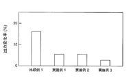
- FIG. 6 is a diagram showing experimental results regarding the output change rate of Comparative Example 1 and Examples 1 to 3. In Example 1, it is the figure which showed the experimental result regarding the output change rate at the time of changing La density
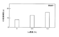
- Example 1 it is the figure which showed the experimental result regarding CS (cold shoot) convergence time at the time of changing La density
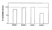
- FIG. 4 is a diagram showing experimental results regarding adhesion strength of porous protective layers of Examples 1 and 2 and Comparative Examples 1 and 2.
- Embodiments 1 and 2 of the gas sensor element of the present invention will be described below with reference to the drawings.
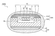
- (Embodiments 1 and 2 of gas sensor element) 1 and 2 are schematic diagrams for explaining Embodiments 1 and 2 of the gas sensor element of the present invention, respectively.
- the illustrated gas sensor element 100 includes a detection unit 10 that detects an oxygen concentration in exhaust gas, a heating unit 20 stacked on the detection unit 10, and moisture around the detection unit 10 and the heating unit 20 in the exhaust gas.
- This is a porous material that prevents the moisture from reaching the detection unit 10 or the heat generation unit 20 and causing the detection unit 10 or the heat generation unit 20 to be cracked by water and traps lead and sulfur as poisonous substances.
- the protective layer 30 is generally configured.
- the detection unit 10 surrounds the solid electrolyte layer 3 including a pair of electrodes 4 including a measured gas side electrode 41 and a reference gas side electrode 42 on both sides, and the measured gas side electrode 41 via the measured gas space 8a.
- a porous diffusion resistance layer 2 that forms a gas layer 8 to be measured together with the porous diffusion resistance layer 2, and a reference gas space protection layer that surrounds the reference gas side electrode 42 via the reference gas space 8b. 5 is roughly constituted.
- the heat generating part 20 is composed of a heat generating source 6 provided with a heater serving as a heat generating element and a heat generating source substrate 7 supporting the same, and forms a heating region of the gas sensor element 100 so as to reach its activation temperature. Heating is controlled.
- the detection unit 10 has a corner portion that is tapered, and the notch ensures the thickness of the porous protective layer 30 at the relevant portion of the detection unit 10. The water resistance of the area is guaranteed.
- the solid electrolyte layer 3 is made of zirconia, and the gas side electrode 41 to be measured and the reference gas side electrode 42 are both made of platinum.
- the shielding layer 1 and the reference gas space protection layer 5 both have a gas-impermeable internal structure, and are both made of alumina.
- a voltage having a phase difference between the oxygen concentration difference and the current is applied to the pair of electrodes 4, the measured gas is brought into contact with the measured gas side electrode 41, and the reference gas side A reference gas such as the atmosphere is brought into contact with the electrode 42, a current value generated between the electrodes is measured according to a difference in oxygen concentration between the two, and the air-fuel ratio of the vehicle engine can be specified based on the measured current.
- the porous diffusion resistance layer 2 is provided at a position that defines a measured gas space 8a around the measured gas side electrode 41 in order to suppress the introduction amount of the measured gas to the measured gas side electrode 41. Hydrogen gas, carbon monoxide gas, oxygen gas, etc. constituting the exhaust gas introduced through the porous protective layer 30 outside the porous diffusion resistance layer 2 are further measured through the porous diffusion resistance layer 2. It is introduced into the gas space 8a.
- the porous protective layer 30 has an effect of burning unburned gas such as hydrogen gas or carbon monoxide gas, which is included in the gas to be measured and may reduce the detection accuracy of the gas sensor element 10, There exists an effect
- the porous protective layer 30 includes a first porous protective layer 31 that directly surrounds the outside of the porous diffusion resistance layer 2, the first porous protective layer 31, the detection unit 10, and the heat generating unit. And a second porous protective layer 32 that surrounds the entirety of 20.
- the first and second porous protective layers 31 and 32 are both formed from a fired product such as alumina particles.
- the second porous protective layer 32 contains at least one of La, Ca, and Mg (any one or two or more).
- the first porous protective layer 31 in direct contact with the porous diffusion resistance layer 2 does not include any of La, Ca, and Mg.
- the first porous protective layer 31 made of an alumina material does not contain La, the alumina forming the first porous protective layer 31 is likely to be unstable, and there is a concern that the strength thereof may be reduced.
- the porous protective layer is formed by arranging the second porous protective layer 32 made of alumina containing La or the like so as to surround the first porous protective layer 31. As a whole, a layer having no fear of strength reduction is formed.
- the content ratio of at least one of La, Ca, and Mg in the second porous protective layer 32 is adjusted to a range of greater than 0% by mass and equal to or less than 1% by mass.
- the output change rate can be reduced to about 1/3 to 1/5 of the conventional product.
- the manufacturing method of the gas sensor element 100 will be outlined. After the detection unit 10 and the heating unit 20 are connected and integrated, an alumina slurry not containing La or the like is applied only around the porous diffusion resistance layer 2 and baked to form the first porous protective layer 31. Form the intermediate. In addition, this process is repeatedly performed until the 1st porous protective layer 31 becomes desired thickness.
- the gas sensor element 100 in which the second porous protective layer 32 is disposed on the outer periphery is manufactured by immersing the intermediate in an alumina slurry containing La or the like, pulling it up and firing it. The dipping and firing are repeated until the second porous protective layer 32 has a desired thickness.
- the illustrated gas sensor element 100A has a configuration in which the first porous protective layer 31A constituting the porous protective layer 30A surrounds not only the porous diffusion resistance layer 2 but also the shielding layer 1. This is different from the gas sensor element 100 in that the surrounding area of the first porous protective layer 31A is large.
- the first porous protective layer 31A not containing La or the like surrounds not only the porous diffusion resistance layer 2 but also the shielding layer 1, that is, directly surrounds the first porous protective layer 31A not containing La or the like. As the area of the detection unit 10 to be increased increases, the output change reduction effect is further enhanced.
- the second porous protective layer 32A made of an alumina material containing La or the like is provided so as to surround the first porous protective layer 10A, thereby providing a porous protective layer.
- the strength of 30A as a whole is guaranteed.
- the rate of change of output when changing the output and the CS (cold shoot) convergence time which indicates the time until the output value shifts to the rich side immediately after the engine starts and converges to a normal value, are verified, and the porous protective layer adheres The strength was also verified.
- FIGS. 3 (a), (b), and (c) are diagrams showing Examples 1, 2, and 3 of gas sensor elements used in the experiment, respectively.
- the test body of Example 1 shown in FIG. 3a simulates the gas sensor element 100 shown in FIG. 1, and the test body of Example 2 shown in FIG. 3b has a second porous protective layer formed in a rectangular parallelepiped shape.
- the specimen of Example 3 shown in FIG. 3c simulates the gas sensor element 100A shown in FIG.
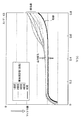
- FIG. 4 shows the verification result of the output change of the sensor before and after poisoning.
- a gas sensor element with a conventional structure this was exposed to an SO 2 gas atmosphere that could not be in a real environment, and sensor characteristics such as gas responsiveness were examined using a model gas apparatus.
- FIG. 4 demonstrates that the sensor output decreases on the rich side. Furthermore, from the high sensitivity analysis of the sensor element surface and fracture surface at that time, it was found that S was strongly localized and adsorbed to La in the porous protective layer as SO 4 2- .
- the degree of influence of S poisoning for each area of the porous protective layer was investigated.
- the influence degree of the area A in the vicinity of the porous diffusion resistance layer is about 77%
- the influence degree of the area B adjacent to the shielding layer is about 15%
- the influence degree of the other wide area C was found to be around 8%.
- Example 3 the output change rate of Comparative Example 1 was 17%, while Examples 1 and 2 were reduced to 6%, and Example 3 was reduced to 3%.
- Example 3 since the range of the first porous protective layer not containing La was widened, the influence of S poisoning in the detection unit was further reduced, which led to a further reduction in the output change rate. It is considered a thing.
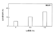
- FIG. 7 shows an experimental result regarding the output change rate when the La concentration in the second porous protective layer is changed
- FIG. 8 shows an experimental result regarding the CS (cold shoot) convergence time.
- FIG. 7 shows that the lower the La concentration, the lower the output change rate.
- it has been found that it is better to contain La from the viewpoint of strength stability of alumina, which is a material for forming the porous protective layer, and considering these comprehensively, in the range of more than 0 and 1% by mass or less. It can be concluded that La should be included in the second porous protective layer.
- FIG. 9 is a diagram showing the experimental results regarding the adhesion strength of the porous protective layer in Examples 1 and 2 and Comparative Examples 1 and 2.
- SYMBOLS 1 Shielding layer, 2 ... Porous diffusion resistance layer, 3 ... Solid electrolyte layer, 4 ... A pair of electrodes, 41 ... Gas to be measured side electrode, 42 ... Reference gas side electrode, 5 ... Reference gas space protective layer, 6 ... Heat source (heater), 7 ... Heat source substrate, 8a ... Gas space to be measured, 8b ... Reference gas space, 10 ... Detection part, 20 ... Heating part, 30, 30A ... Porous protective layer, 31, 31A ... First Porous protective layer, 32, 32A, second porous protective layer, 100, 100A, gas sensor element
Landscapes
- Chemical & Material Sciences (AREA)
- Health & Medical Sciences (AREA)
- Life Sciences & Earth Sciences (AREA)
- Physics & Mathematics (AREA)
- Engineering & Computer Science (AREA)
- General Physics & Mathematics (AREA)
- Pathology (AREA)
- Analytical Chemistry (AREA)
- Biochemistry (AREA)
- General Health & Medical Sciences (AREA)
- Immunology (AREA)
- Molecular Biology (AREA)
- Electrochemistry (AREA)
- Chemical Kinetics & Catalysis (AREA)
- Combustion & Propulsion (AREA)
- Food Science & Technology (AREA)
- Medicinal Chemistry (AREA)
- Biomedical Technology (AREA)
- Biophysics (AREA)
- Hematology (AREA)
- Urology & Nephrology (AREA)
- Emergency Medicine (AREA)
- Measuring Oxygen Concentration In Cells (AREA)
Abstract
燃料や排ガス中にエタノールが含有され、さらにはその含有量が多いことにより、ガスセンサ素子がS被毒される場合であっても、応答性能の低下が抑制されるガスセンサ素子を提供する。 一対の電極4を両側に備えた固体電解質層3、多孔質拡散抵抗層2とともに被測定ガス空間8aを画成する遮蔽層1、基準ガス空間保護層5から構成される検知部10と、検知部10に積層した発熱部20と、検知部10および発熱部20を包囲する多孔質保護層30と、からなるガスセンサ素子100であり、多孔質保護層30は、少なくとも多孔質拡散抵抗層2を包囲する第一の多孔質保護層31と、第一の多孔質保護層31を包囲するとともに検知部10および発熱部20を包囲する第二の多孔質保護層32とから構成されており、第一の多孔質保護層31はLa、Ca、Mgのいずれも含んでおらず、第二の多孔質保護層32はLa、Ca、Mgの少なくとも一種を含んでいる。
Description
本発明は、被測定ガス中の特定ガス濃度を検出するガスセンサ素子に関するものである。
各種産業界においては、環境影響負荷低減に向けた様々な取り組みが世界規模でおこなわれており、中でも、自動車産業においては、燃費性能に優れたガソリンエンジン車は勿論のこと、ハイブリッド車や電気自動車等のいわゆるエコカーの普及とそのさらなる性能向上に向けた開発が日々進められている。
車両の燃費性能の測定に関しては、排気ガス等の被測定ガス中の酸素濃度をガスセンサにて検知し、大気中の酸素を基準ガスとしてこの酸素濃度との差を求めることによっておこなわれている。
このガスセンサを構成するガスセンサ素子の一つの実施形態の具体的な構成としては、被測定ガス側電極と基準ガス側電極からなる一対の電極を両側に備えた固体電解質層と、被測定ガス側電極を被測定ガス空間を介して包囲する多孔質拡散抵抗層(もしくは拡散律速層)と、多孔質拡散抵抗層とともに被測定ガス空間を画成する遮蔽層と、基準ガス側電極を基準ガス空間を介して包囲する基準ガス空間保護層とから構成される検知部と、ヒータ等の発熱源を備えた発熱部と、これら検知部および発熱部を包囲する多孔質保護層(もしくは触媒担持保護層、触媒担持トラップ層)とから大略構成されるものが一般的である。たとえば酸素やHC等のリッチガスが多孔質拡散抵抗層を介して被測定ガス側電極に到達する拡散律速によって出力電流が決定され、たとえばA/Fセンサの場合にはA/F値が検出されることになる。
上記するガスセンサは700℃以上もの高温雰囲気下で排気ガス中の酸素濃度を検知することから、この排気ガス中の水滴がガスセンサを構成するガスセンサ素子に衝突すると部分急冷による熱衝撃が生じ、温度変化に伴う体積変化によって該素子に被水割れが発生し、センシング機能が損なわれるといった課題を有している。この課題に対して、上記する多孔質保護層にて検知部等が包囲された形態のガスセンサ素子を適用することにより、検知部や発熱部への水滴の衝突が触媒担持保護層で効果的に抑制される。なお、素子の周囲をアルミナからなる多孔質保護層で包囲してなるガスセンサ素子に関する技術が特許文献1,2に開示されている。
ところで、上記する燃費性能に優れたガソリンエンジン車やハイブリッド車において使用されるガソリンにおいて、地域によって存在する粗悪燃料が使用される場合には、このような燃料に含有されているS成分の増加に起因したSOx被毒(もしくはS被毒)による性能劣化も危惧される。
ガスセンサ素子がS被毒することでセンサ出力が低下することより、S被毒によってもセンサ出力低下を抑制可能なガスセンサ素子の開発が当該技術分野において急務の課題となっている。
本発明は上記する問題に鑑みてなされたものであり、燃料や排ガス中に存在するS含有量が多いことにより、ガスセンサ素子がS被毒される場合であっても、センサ出力の低下が抑制されるガスセンサ素子を提供することを目的とする。
前記目的を達成すべく、本発明によるガスセンサ素子は、被測定ガス側電極と基準ガス側電極からなる一対の電極を両側に備えた固体電解質層、被測定ガス側電極を被測定ガス空間を介して包囲する多孔質拡散抵抗層、多孔質拡散抵抗層とともに被測定ガス空間を画成する遮蔽層、基準ガス側電極を基準ガス空間を介して包囲する基準ガス空間保護層、から構成される検知部と、前記検知部に積層して発熱源を具備する発熱部と、前記検知部および前記発熱部を包囲する多孔質保護層と、からなるガスセンサ素子であって、前記多孔質保護層は、少なくとも多孔質拡散抵抗層を包囲する第一の多孔質保護層と、該第一の多孔質保護層を包囲するとともに前記検知部および前記発熱部を包囲する第二の多孔質保護層とから構成されており、前記第一の多孔質保護層はLa、Ca、Mgのいずれも含んでおらず、前記第二の多孔質保護層はLa、Ca、Mgの少なくとも一種を含んでいるものである。
本発明のガスセンサ素子は、検知部等を包囲する多孔質保護層を二層積層構造とし、検知部を構成する多孔質拡散抵抗層を少なくとも包囲する第一の多孔質保護層はLa、Ca、Mgのいずれも含んでおらず、第一の多孔質保護層を包囲する第二の多孔質保護層はLa、Ca、Mgの少なくとも一種を含んでいる構成を適用したことにより、センサの出力変化に大きな影響のあるガスの入り口に当たる多孔質拡散抵抗層へのS被毒を抑制しながら、La等を含有する第二の多孔質拡散抵抗層にて多孔質保護層の全体的な強度を保証可能としたものである。
第一、第二の多孔質保護層はいずれもアルミナ粒子等の焼成物から形成でき、第二の多孔質保護層は、その中にLa、Ca、Mgの少なくとも一種(いずれか一種もしくは二種以上)が含有され、一方で第一の多孔質保護層はLa、Ca、Mgのいずれも含んでいない。なお、第一及び第二の多孔質保護層は、アルミナ粒子以外のセラミックス、もしくは金属間化合物であってもよい。
本発明者等の検証によれば、S被毒したガスセンサを精査した結果、多孔質保護層内に存在するLaにSO4
2-が強く局在して吸着していることが分かっており、このことが原因でリッチ時にセンサの出力変化が生じることが明らかにされている。より詳細には、このSO4
2-の還元にHCガスが消費されることが出力変化の主要因であり、多孔質保護層の中でも、多孔質拡散抵抗層へガスが流入するエリア内における残留Sが出力変化に多大な影響を与えていることが特定されている。
そこで、多孔質拡散抵抗層へガスが流入するエリア(多孔質拡散抵抗層に直接接しているエリア)に形成されている第一の多孔質保護層にLa等を含有させないことで当該エリアにおける残留Sを抑制でき、もってセンサの出力変化を可及的に抑制することが可能になる。
その一方で、たとえばアルミナから形成されている第一の多孔質保護層はLa等が存在しないことで不安定になり、強度低下が懸念されるものの、第一の多孔質保護層を包囲するようにしてLa等が含有された第二の多孔質保護層が存在することで多孔質保護層全体としては強度低下のないものとなる。
また、本発明によるガスセンサ素子の好ましい実施の形態において、前記第二の多孔質保護層におけるLa、Ca、Mgの少なくとも一種の含有割合は、0質量%より大きく1質量%以下の範囲である。
本発明者等がLaを対象として多孔質保護層中の濃度を0質量%より大きく1質量%以下の範囲に調整してセンサの出力変化を検証した結果、従来のLa濃度が1質量%を超えるものとの比較において、出力変化率は従来品の1/3~1/5程度にまで低減することが実証されている。
また、本発明によるガスセンサ素子の好ましい実施の形態において、前記第一の多孔質保護層は多孔質拡散抵抗層と遮蔽層を包囲しているものである。
La等を含有しない第一の多孔質保護層が多孔質拡散抵抗層のみならず、遮蔽層をも包囲すること、すなわちLa等の存在しない第一の多孔質保護層に直接包囲される検知部領域が多くなることで、出力変化低減効果がより一層高くなることが本発明者等によって実証されている。
このように、本発明によるガスセンサ素子は、車両用内燃機関の排気系統に設置されて、排ガスフィードバックシステムに適用される空燃比センサ素子(A/Fセンサ素子)や、排ガス中の酸素濃度を測定する酸素センサ素子、三元触媒の劣化検知等に利用するNOx等の大気汚染物質濃度を測定するNOxセンサ素子として適用することができる。
以上の説明から理解できるように、本発明のガスセンサ素子によれば、検知部等を包囲する多孔質保護層を二層積層構造とし、検知部を構成する多孔質拡散抵抗層を少なくとも包囲する第一の多孔質保護層はLa、Ca、Mgのいずれも含んでおらず、第一の多孔質保護層を包囲する第二の多孔質保護層はLa、Ca、Mgの少なくとも一種を含んでいる構成を適用したことにより、センサの出力変化に大きな影響のあるガスの入り口に当たる多孔質拡散抵抗層へのS被毒を抑制しながら、La等を含有する第二の多孔質拡散抵抗層にて多孔質保護層の全体的な強度を保証することができる。
以下、図面を参照して本発明のガスセンサ素子の実施の形態1,2を説明する。
(ガスセンサ素子の実施の形態1,2)
図1,2はそれぞれ、本発明のガスセンサ素子の実施の形態1,2を説明した模式図である。
(ガスセンサ素子の実施の形態1,2)
図1,2はそれぞれ、本発明のガスセンサ素子の実施の形態1,2を説明した模式図である。
まず、図1を参照してその具体的な構成を説明する。図示するガスセンサ素子100は、排気ガス中の酸素濃度を検知する検知部10と、この検知部10に積層される発熱部20と、これら検知部10および発熱部20の周囲を排気ガス中の水分から防護して、この水分が検知部10または発熱部20に到達して検知部10または発熱部20が被水割れするのを抑制するとともに、被毒物質である鉛や硫黄をトラップする多孔質保護層30とから大略構成されている。
検知部10は、被測定ガス側電極41と基準ガス側電極42からなる一対の電極4を両側に備えた固体電解質層3と、被測定ガス側電極41を被測定ガス空間8aを介して包囲する多孔質拡散抵抗層2と、多孔質拡散抵抗層2とともに被測定ガス空間8aを画成する遮蔽層1と、基準ガス側電極42を基準ガス空間8bを介して包囲する基準ガス空間保護層5とから大略構成されている。
一方、発熱部20は、発熱体となるヒータを備えた発熱源6とこれを支持する発熱源基板7から構成されており、ガスセンサ素子100の加熱領域を形成してその活性温度となるように加熱制御される。
検知部10は、図示する横断面形状において、その隅角部がテーパー状に切欠かれており、この切欠きによって、検知部10の当該箇所における多孔質保護層30の厚みを保証し、もって当該領域の耐被水性が保証されている。
固体電解質層3はジルコニアから形成されており、被測定ガス側電極41と基準ガス側電極42はともに白金から形成されている。また、遮蔽層1と基準ガス空間保護層5はともにガス不透過な内部構造を呈し、ともにアルミナから形成されている。
空燃比センサ素子を例に取り上げると、一対の電極4に対し、酸素濃度差と電流がリニアな相間を有する電圧を印加し、被測定ガス側電極41に被測定ガスを接触させ、基準ガス側電極42には大気等の基準ガスを接触させ、双方の酸素濃度差に応じて電極間に生じる電流値を測定し、測定電流に基づいて車両エンジンの空燃比を特定することができる。
多孔質拡散抵抗層2は、被測定ガス側電極41に対する被測定ガスの導入量を抑制するために被測定ガス側電極41の周囲の被測定ガス空間8aを画成する位置に設けてあり、多孔質拡散抵抗層2の外側にある多孔質保護層30を介して導入された排気ガスを構成する水素ガスや一酸化炭素ガス、酸素ガスなどがさらに多孔質拡散抵抗層2を介して被測定ガス空間8aに導入されるようになっている。
多孔質保護層30は、被測定ガス中に含まれてガスセンサ素子10の検出精度を低下させる恐れのある、水素ガスや一酸化炭素ガスなどの未燃焼ガスを燃焼させる作用を奏することのほか、鉛やケイ素、リンなどの被測定ガス側電極41を被毒させる被毒物質を捕集する作用を奏する。
より具体的には、多孔質保護層30は多孔質拡散抵抗層2の外側を直接包囲する第一の多孔質保護層31と、第一の多孔質保護層31と検知部10、および発熱部20の全体を包囲する第二の多孔質保護層32とから構成されている。
第一、第二の多孔質保護層31,32はいずれもアルミナ粒子等の焼成物から形成される。そして、第二の多孔質保護層32は、その中にLa、Ca、Mgの少なくとも一種(いずれか一種もしくは二種以上)が含有されている。一方、多孔質拡散抵抗層2に直接接する第一の多孔質保護層31はLa、Ca、Mgのいずれも含んでいない。
このように、多孔質拡散抵抗層2へガスが流入する当該多孔質拡散抵抗層2に直接接するエリアに形成されている第一の多孔質保護層31にLa等を含有させないことにより、当該エリアにおける残留Sを効果的に抑制することができ、もってセンサの出力変化を可及的に抑制することができる。
多孔質保護層30内に存在するLaにはSO4
2-が強く局在して吸着していることが分かっており、このSO4
2-の還元にHCガスが消費されることが出力変化の主要因となっていることが解明されており、さらに、多孔質保護層30の中でも多孔質拡散抵抗層2へガスが直接流入するエリア内における残留Sが出力変化に多大な影響を与えているとの知見に基づき、第一の多孔質保護層31にLa等を含有させない構成を適用したものである。
このようにアルミナ素材の第一の多孔質保護層31がLaを含有しないことで、第一の多孔質保護層31を形成するアルミナが不安定化し易く、その強度低下が懸念される。
これに対し、図示するガスセンサ素子100では、第一の多孔質保護層31を包囲するようにLa等を含有したアルミナ素材の第二の多孔質保護層32を配したことにより、多孔質保護層30全体としては強度低下の懸念のない層が形成されている。
なお、第二の多孔質保護層32におけるLa、Ca、Mgの少なくとも一種の含有割合は、0質量%より大きく1質量%以下の範囲に調整されているのが好ましい。
後述するように、従来のLa濃度が1質量%を超えるものとの比較において、出力変化率は従来品の1/3~1/5程度にまで低減できるという検証結果によるものである。
ここで、ガスセンサ素子100の製造方法を概説する。検知部10と発熱部20を接続して一体化した後、多孔質拡散抵抗層2の周囲にのみLa等を含まないアルミナスラリーを塗工し、焼成して第一の多孔質保護層31を形成して中間体を製作する。なお、第一の多孔質保護層31が所望厚となるまで、この工程が繰り返し実行される。
次いで、La等が含有されたアルミナスラリー中に中間体を浸漬し、引き上げて焼成することにより、第二の多孔質保護層32が外周に配設されたガスセンサ素子100が製作される。なお、第二の多孔質保護層32も所望厚となるまで、この浸漬と焼成が繰り返し実行される。
次に、図2を参照してガスセンサ素子の実施の形態2を説明する。図示するガスセンサ素子100Aは、多孔質保護層30Aを構成する第一の多孔質保護層31Aが多孔質拡散抵抗層2のみならず、遮蔽層1をも包囲している形態であり、このように第一の多孔質保護層31Aの包囲領域が多い点でガスセンサ素子100と相違している。
La等を含有しない第一の多孔質保護層31Aが多孔質拡散抵抗層2のみならず、遮蔽層1をも包囲すること、すなわちLa等の存在しない第一の多孔質保護層31Aに直接包囲される検知部10の領域が多くなることで、出力変化低減効果がより一層高くなる。
また、ガスセンサ素子100Aにおいても、第一の多孔質保護層10Aを包囲するようにしてLa等が含有されたアルミナ素材の第二の多孔質保護層32Aが配されることで、多孔質保護層30A全体としての強度が保証される。
(本発明のガスセンサ素子の性能を評価する実験とその結果)
本発明者等は、本発明のガスセンサ素子の性能を評価する実験をおこなった。より詳細には、被毒前後のセンサの出力変化を検証し、また、多孔質保護層のエリアごとのS被毒の影響度合いを検証し、さらには、第二の多孔質保護層におけるLa濃度を変化させた際の出力変化率やエンジン始動直後に出力値がリッチ側にずれ、正常な値に収束するまでの時間を示すCS(コールドシュート)収束時間を検証し、多孔質保護層の付着強度についても検証した。
(本発明のガスセンサ素子の性能を評価する実験とその結果)
本発明者等は、本発明のガスセンサ素子の性能を評価する実験をおこなった。より詳細には、被毒前後のセンサの出力変化を検証し、また、多孔質保護層のエリアごとのS被毒の影響度合いを検証し、さらには、第二の多孔質保護層におけるLa濃度を変化させた際の出力変化率やエンジン始動直後に出力値がリッチ側にずれ、正常な値に収束するまでの時間を示すCS(コールドシュート)収束時間を検証し、多孔質保護層の付着強度についても検証した。
まず、図3(a)、(b)、(c)はそれぞれ、実験で使用したガスセンサ素子の実施例1、2、3を示した図である。図3aで示す実施例1の試験体は図1で示すガスセンサ素子100を模擬したものであり、図3bで示す実施例2の試験体は第二の多孔質保護層を直方体形状に製作したものであり、図3cで示す実施例3の試験体は図2で示すガスセンサ素子100Aを模擬したものである。
まず、図4に、被毒前後のセンサの出力変化の検証結果を示す。従来構造のガスセンサ素子を用いて、これを実環境ではあり得ないほど高濃度のSO2ガス雰囲気に曝し、モデルガス装置を用いてガス応答性等のセンサ特性を精査した。
図4より、リッチ側においてセンサ出力が低下することが実証されている。さらに、その際のセンサ素子の表面と破断面の高感度分析より、SはSO4
2-として多孔質保護層の中のLaに強く局在して吸着していることが分かった。
また、同図で示すように、通常の特性評価を繰り返しても、センサの出力変化が回復しないことが分かった。
そこで、出力回復条件を調査した結果、出力回復にはかなりのリッチ条件と素子温度の上昇が必要であることが分かった。
このような条件にてLaに吸着したSO4
2-が還元脱離すると考えられるが、実際のエンジン作動時にこのような条件を形成するのは不可能であることから、このような出力変化を起こさせない構造にする必要性を確認した。
次に、多孔質保護層のエリアごとのS被毒の影響の程度を調査した。その結果、図5に示す通り、多孔質拡散抵抗層の近傍エリアAの影響度は77%程度、遮蔽層に隣接するエリアBの影響度は15%程度、その他の広範囲のエリアCの影響度は8%程度であることが分かった。
この検証結果より、多孔質拡散抵抗層の近傍エリアAにおけるS被毒を抑制することで、センサの出力変化を効果的に抑制できるとの方向性が明確になった。
実施例1~3と比較例1(従来品であって、第一の多孔質保護層にもLaが含有されている形態)を用いて、まず、センサの出力変化率を検証した。その結果を図6に示す。
図6より、比較例1の出力変化率が17%であるのに対して、実施例1、2は6%にまで低減し、実施例3は3%にまで低減する結果となった。実施例3では、Laを含有しない第一の多孔質保護層の範囲が広くなったことで検知部におけるS被毒の影響が一層低減し、このことが出力変化率の一層の低減に繋がったものと考えられる。
次に、第二の多孔質保護層におけるLa濃度を変化させた際の出力変化率に関する実験結果を図7に示し、CS(コールドシュート)収束時間に関する実験結果を図8に示す。
図7より、La濃度が低い方が出力変化率が低くなることが分かる。ただし、多孔質保護層の形成素材であるアルミナの強度安定性の観点からLaを含有するのがよいことが分かっており、これらを総合勘案して、0より多く、1質量%以下の範囲でLaを第二の多孔質保護層に含有させるのがよいと結論付けることができる。
また、図8より、CS収束時間に関しても出力変化率と同様の傾向を示す結果が得られている。
さらに、図9は、実施例1、2と比較例1、2の多孔質保護層付着強度に関する実験結果を示した図である。
第一、第二の多孔質保護層の双方にLaが含有されている比較例1を付着強度の基準100とした際に、実施例2では95程度と比較例1程度の付着強度が得られること、実施例1でも85程度の付着強度が得られることが実証されており、第一の多孔質保護層にLaが含有されない場合でも、十分な付着強度を有していることが実証されている。
以上、本発明の実施の形態を図面を用いて詳述してきたが、具体的な構成はこの実施形態に限定されるものではなく、本発明の要旨を逸脱しない範囲における設計変更等があっても、それらは本発明に含まれるものである。
1…遮蔽層、2…多孔質拡散抵抗層、3…固体電解質層、4…一対の電極、41…被測定ガス側電極、42…基準ガス側電極、5…基準ガス空間保護層、6…発熱源(ヒータ)、7…発熱源基板、8a…被測定ガス空間、8b…基準ガス空間、10…検知部、20…加熱部、30,30A…多孔質保護層、31,31A…第一の多孔質保護層、32,32A…第二の多孔質保護層、100,100A…ガスセンサ素子
Claims (3)
- 被測定ガス側電極と基準ガス側電極からなる一対の電極を両側に備えた固体電解質層、
被測定ガス側電極を被測定ガス空間を介して包囲する多孔質拡散抵抗層、
多孔質拡散抵抗層とともに被測定ガス空間を画成する遮蔽層、
基準ガス側電極を基準ガス空間を介して包囲する基準ガス空間保護層、から構成される検知部と、
前記検知部に積層して発熱源を具備する発熱部と、
前記検知部および前記発熱部を包囲する多孔質保護層と、からなるガスセンサ素子であって、
前記多孔質保護層は、少なくとも多孔質拡散抵抗層を包囲する第一の多孔質保護層と、該第一の多孔質保護層を包囲するとともに前記検知部および前記発熱部を包囲する第二の多孔質保護層とから構成されており、
前記第一の多孔質保護層はLa、Ca、Mgのいずれも含んでおらず、
前記第二の多孔質保護層はLa、Ca、Mgの少なくとも一種を含んでいるガスセンサ素子。 - 前記第二の多孔質保護層におけるLa、Ca、Mgの少なくとも一種の含有割合は、0質量%より大きく1質量%以下の範囲である請求項1に記載のガスセンサ素子。
- 前記第一の多孔質保護層は多孔質拡散抵抗層と遮蔽層を包囲している請求項1または2に記載のガスセンサ素子。
Priority Applications (3)
| Application Number | Priority Date | Filing Date | Title |
|---|---|---|---|
| CN201680003662.1A CN107076697B (zh) | 2015-03-17 | 2016-02-12 | 气体传感元件 |
| DE112016001244.6T DE112016001244B4 (de) | 2015-03-17 | 2016-02-12 | Gassensorelement |
| US15/545,864 US10371659B2 (en) | 2015-03-17 | 2016-02-12 | Gas sensor element |
Applications Claiming Priority (2)
| Application Number | Priority Date | Filing Date | Title |
|---|---|---|---|
| JP2015-053933 | 2015-03-17 | ||
| JP2015053933A JP6580845B2 (ja) | 2015-03-17 | 2015-03-17 | ガスセンサ素子 |
Publications (1)
| Publication Number | Publication Date |
|---|---|
| WO2016147768A1 true WO2016147768A1 (ja) | 2016-09-22 |
Family
ID=56919015
Family Applications (1)
| Application Number | Title | Priority Date | Filing Date |
|---|---|---|---|
| PCT/JP2016/054059 Ceased WO2016147768A1 (ja) | 2015-03-17 | 2016-02-12 | ガスセンサ素子 |
Country Status (5)
| Country | Link |
|---|---|
| US (1) | US10371659B2 (ja) |
| JP (1) | JP6580845B2 (ja) |
| CN (1) | CN107076697B (ja) |
| DE (1) | DE112016001244B4 (ja) |
| WO (1) | WO2016147768A1 (ja) |
Families Citing this family (7)
| Publication number | Priority date | Publication date | Assignee | Title |
|---|---|---|---|---|
| JP6909706B2 (ja) * | 2017-10-31 | 2021-07-28 | 株式会社デンソー | ガスセンサ |
| JP6998801B2 (ja) * | 2018-03-12 | 2022-02-04 | 日本碍子株式会社 | ガスセンサ |
| JP7090211B2 (ja) * | 2019-03-29 | 2022-06-23 | 日本碍子株式会社 | ガスセンサのセンサ素子 |
| JP7070514B2 (ja) | 2019-06-27 | 2022-05-18 | 株式会社デンソー | ガスセンサ及びその製造方法 |
| JP7284088B2 (ja) * | 2019-12-26 | 2023-05-30 | 日本碍子株式会社 | ガスセンサのセンサ素子 |
| JP7523398B2 (ja) * | 2021-03-31 | 2024-07-26 | 日本碍子株式会社 | ガスセンサ |
| JP2023112453A (ja) * | 2022-02-01 | 2023-08-14 | 日本碍子株式会社 | ガスセンサ素子 |
Citations (3)
| Publication number | Priority date | Publication date | Assignee | Title |
|---|---|---|---|---|
| JPH0344659U (ja) * | 1989-09-07 | 1991-04-25 | ||
| JP2014089074A (ja) * | 2012-10-29 | 2014-05-15 | Denso Corp | ガスセンサ素子の製造方法及びそれによって得られるガスセンサ素子 |
| JP2015059758A (ja) * | 2013-09-17 | 2015-03-30 | 日本特殊陶業株式会社 | ガスセンサ素子及びガスセンサ |
Family Cites Families (11)
| Publication number | Priority date | Publication date | Assignee | Title |
|---|---|---|---|---|
| JPS61241657A (ja) * | 1985-04-19 | 1986-10-27 | Nissan Motor Co Ltd | 酸素センサ素子 |
| JP4014623B2 (ja) | 2002-02-28 | 2007-11-28 | 日本特殊陶業株式会社 | ガスセンサ |
| GB2387230B (en) | 2002-02-28 | 2005-12-21 | Ngk Spark Plug Co | Prismatic ceramic heater for heating gas sensor element, prismatic gas sensor element in multi-layered structure including the prismatic ceramic heater, |
| US7097875B2 (en) * | 2002-12-19 | 2006-08-29 | Delphi Technologies, Inc | Methods of making gas sensors and sensors formed therefrom |
| DE10260849B4 (de) * | 2002-12-23 | 2017-05-24 | Robert Bosch Gmbh | Meßfühler |
| CN101008630A (zh) * | 2006-01-23 | 2007-08-01 | 株式会社电装 | 用于气体传感器的气体检测元件及制造该元件的方法 |
| JP5056723B2 (ja) | 2008-10-31 | 2012-10-24 | 株式会社デンソー | ガスセンサ素子 |
| JP5287807B2 (ja) * | 2009-10-28 | 2013-09-11 | 株式会社デンソー | ガスセンサ素子 |
| JP6359373B2 (ja) * | 2013-09-05 | 2018-07-18 | 日本特殊陶業株式会社 | ガスセンサ素子及びガスセンサ |
| CN103604851B (zh) * | 2013-11-26 | 2015-10-21 | 武汉锆元传感技术有限公司 | 一种车用汽车尾气传感器外电极保护层及制备方法 |
| CN104142363A (zh) * | 2014-07-17 | 2014-11-12 | 厦门宏发电力电器有限公司 | 一种片式结构氧传感器及其制作方法 |
-
2015
- 2015-03-17 JP JP2015053933A patent/JP6580845B2/ja active Active
-
2016
- 2016-02-12 CN CN201680003662.1A patent/CN107076697B/zh active Active
- 2016-02-12 DE DE112016001244.6T patent/DE112016001244B4/de active Active
- 2016-02-12 WO PCT/JP2016/054059 patent/WO2016147768A1/ja not_active Ceased
- 2016-02-12 US US15/545,864 patent/US10371659B2/en active Active
Patent Citations (3)
| Publication number | Priority date | Publication date | Assignee | Title |
|---|---|---|---|---|
| JPH0344659U (ja) * | 1989-09-07 | 1991-04-25 | ||
| JP2014089074A (ja) * | 2012-10-29 | 2014-05-15 | Denso Corp | ガスセンサ素子の製造方法及びそれによって得られるガスセンサ素子 |
| JP2015059758A (ja) * | 2013-09-17 | 2015-03-30 | 日本特殊陶業株式会社 | ガスセンサ素子及びガスセンサ |
Also Published As
| Publication number | Publication date |
|---|---|
| DE112016001244T5 (de) | 2017-12-14 |
| CN107076697A (zh) | 2017-08-18 |
| JP2016173323A (ja) | 2016-09-29 |
| US20180017514A1 (en) | 2018-01-18 |
| US10371659B2 (en) | 2019-08-06 |
| CN107076697B (zh) | 2019-05-10 |
| JP6580845B2 (ja) | 2019-09-25 |
| DE112016001244B4 (de) | 2020-11-05 |
Similar Documents
| Publication | Publication Date | Title |
|---|---|---|
| JP6580845B2 (ja) | ガスセンサ素子 | |
| JP5530950B2 (ja) | ガスセンサ素子とガスセンサ | |
| US9891139B2 (en) | Catalyst deterioration diagnosis system and catalyst deterioration diagnosis method | |
| US9939348B2 (en) | Catalyst deterioration diagnosis method | |
| CN106246306B (zh) | 用于进行NOx自诊断测试的系统和方法 | |
| JP6475074B2 (ja) | ガスセンサ素子 | |
| EP3029292B1 (en) | Catalyst deterioration diagnosis method | |
| US20110089032A1 (en) | Gas sensor element and its manufacturing method, and gas sensor employing the gas sensor element | |
| US20120297861A1 (en) | Gas sensor element and its manufacturing method, and gas sensor employing the gas sensor element | |
| JP2002048758A (ja) | ガスセンサ素子及びその製造方法 | |
| JP4800853B2 (ja) | ガスセンサ素子 | |
| US10400649B2 (en) | Ammonia sensor calibration method | |
| US20070215468A1 (en) | Gas sensor element and method of manufacturing gas sensor element | |
| JP5287795B2 (ja) | ガスセンサ | |
| JP4385451B2 (ja) | ガスセンサ素子 | |
| JP2012163345A (ja) | 酸素センサ | |
| US9709522B2 (en) | Solid electrolyte gas sensor element and gas sensor | |
| JP2012127672A (ja) | ガスセンサ素子とガスセンサ | |
| US11782016B2 (en) | Gas sensor | |
| JP5637083B2 (ja) | ガスセンサ素子とガスセンサ | |
| JP2014215230A (ja) | ガスセンサ素子 |
Legal Events
| Date | Code | Title | Description |
|---|---|---|---|
| 121 | Ep: the epo has been informed by wipo that ep was designated in this application |
Ref document number: 16764599 Country of ref document: EP Kind code of ref document: A1 |
|
| WWE | Wipo information: entry into national phase |
Ref document number: 15545864 Country of ref document: US |
|
| WWE | Wipo information: entry into national phase |
Ref document number: 112016001244 Country of ref document: DE |
|
| 122 | Ep: pct application non-entry in european phase |
Ref document number: 16764599 Country of ref document: EP Kind code of ref document: A1 |