WO2016143783A1 - 共役ジエンの製造方法 - Google Patents
共役ジエンの製造方法 Download PDFInfo
- Publication number
- WO2016143783A1 WO2016143783A1 PCT/JP2016/057162 JP2016057162W WO2016143783A1 WO 2016143783 A1 WO2016143783 A1 WO 2016143783A1 JP 2016057162 W JP2016057162 W JP 2016057162W WO 2016143783 A1 WO2016143783 A1 WO 2016143783A1
- Authority
- WO
- WIPO (PCT)
- Prior art keywords
- coolant
- conjugated diene
- heat exchanger
- producing
- cooling
- Prior art date
Links
Images


Classifications
-
- B—PERFORMING OPERATIONS; TRANSPORTING
- B01—PHYSICAL OR CHEMICAL PROCESSES OR APPARATUS IN GENERAL
- B01J—CHEMICAL OR PHYSICAL PROCESSES, e.g. CATALYSIS OR COLLOID CHEMISTRY; THEIR RELEVANT APPARATUS
- B01J23/00—Catalysts comprising metals or metal oxides or hydroxides, not provided for in group B01J21/00
- B01J23/002—Mixed oxides other than spinels, e.g. perovskite
-
- B—PERFORMING OPERATIONS; TRANSPORTING
- B01—PHYSICAL OR CHEMICAL PROCESSES OR APPARATUS IN GENERAL
- B01J—CHEMICAL OR PHYSICAL PROCESSES, e.g. CATALYSIS OR COLLOID CHEMISTRY; THEIR RELEVANT APPARATUS
- B01J23/00—Catalysts comprising metals or metal oxides or hydroxides, not provided for in group B01J21/00
- B01J23/70—Catalysts comprising metals or metal oxides or hydroxides, not provided for in group B01J21/00 of the iron group metals or copper
- B01J23/76—Catalysts comprising metals or metal oxides or hydroxides, not provided for in group B01J21/00 of the iron group metals or copper combined with metals, oxides or hydroxides provided for in groups B01J23/02 - B01J23/36
- B01J23/84—Catalysts comprising metals or metal oxides or hydroxides, not provided for in group B01J21/00 of the iron group metals or copper combined with metals, oxides or hydroxides provided for in groups B01J23/02 - B01J23/36 with arsenic, antimony, bismuth, vanadium, niobium, tantalum, polonium, chromium, molybdenum, tungsten, manganese, technetium or rhenium
- B01J23/85—Chromium, molybdenum or tungsten
- B01J23/88—Molybdenum
- B01J23/887—Molybdenum containing in addition other metals, oxides or hydroxides provided for in groups B01J23/02 - B01J23/36
- B01J23/8876—Arsenic, antimony or bismuth
-
- C—CHEMISTRY; METALLURGY
- C07—ORGANIC CHEMISTRY
- C07C—ACYCLIC OR CARBOCYCLIC COMPOUNDS
- C07C11/00—Aliphatic unsaturated hydrocarbons
- C07C11/12—Alkadienes
- C07C11/16—Alkadienes with four carbon atoms
- C07C11/167—1, 3-Butadiene
-
- C—CHEMISTRY; METALLURGY
- C07—ORGANIC CHEMISTRY
- C07C—ACYCLIC OR CARBOCYCLIC COMPOUNDS
- C07C45/00—Preparation of compounds having >C = O groups bound only to carbon or hydrogen atoms; Preparation of chelates of such compounds
- C07C45/78—Separation; Purification; Stabilisation; Use of additives
- C07C45/81—Separation; Purification; Stabilisation; Use of additives by change in the physical state, e.g. crystallisation
-
- C—CHEMISTRY; METALLURGY
- C07—ORGANIC CHEMISTRY
- C07C—ACYCLIC OR CARBOCYCLIC COMPOUNDS
- C07C5/00—Preparation of hydrocarbons from hydrocarbons containing the same number of carbon atoms
- C07C5/42—Preparation of hydrocarbons from hydrocarbons containing the same number of carbon atoms by dehydrogenation with a hydrogen acceptor
- C07C5/48—Preparation of hydrocarbons from hydrocarbons containing the same number of carbon atoms by dehydrogenation with a hydrogen acceptor with oxygen as an acceptor
-
- C—CHEMISTRY; METALLURGY
- C07—ORGANIC CHEMISTRY
- C07C—ACYCLIC OR CARBOCYCLIC COMPOUNDS
- C07C7/00—Purification; Separation; Use of additives
- C07C7/09—Purification; Separation; Use of additives by fractional condensation
-
- C—CHEMISTRY; METALLURGY
- C07—ORGANIC CHEMISTRY
- C07C—ACYCLIC OR CARBOCYCLIC COMPOUNDS
- C07C7/00—Purification; Separation; Use of additives
- C07C7/11—Purification; Separation; Use of additives by absorption, i.e. purification or separation of gaseous hydrocarbons with the aid of liquids
-
- B—PERFORMING OPERATIONS; TRANSPORTING
- B01—PHYSICAL OR CHEMICAL PROCESSES OR APPARATUS IN GENERAL
- B01J—CHEMICAL OR PHYSICAL PROCESSES, e.g. CATALYSIS OR COLLOID CHEMISTRY; THEIR RELEVANT APPARATUS
- B01J2523/00—Constitutive chemical elements of heterogeneous catalysts
-
- C—CHEMISTRY; METALLURGY
- C07—ORGANIC CHEMISTRY
- C07B—GENERAL METHODS OF ORGANIC CHEMISTRY; APPARATUS THEREFOR
- C07B61/00—Other general methods
-
- C—CHEMISTRY; METALLURGY
- C07—ORGANIC CHEMISTRY
- C07C—ACYCLIC OR CARBOCYCLIC COMPOUNDS
- C07C2523/00—Catalysts comprising metals or metal oxides or hydroxides, not provided for in group C07C2521/00
- C07C2523/70—Catalysts comprising metals or metal oxides or hydroxides, not provided for in group C07C2521/00 of the iron group metals or copper
- C07C2523/76—Catalysts comprising metals or metal oxides or hydroxides, not provided for in group C07C2521/00 of the iron group metals or copper combined with metals, oxides or hydroxides provided for in groups C07C2523/02 - C07C2523/36
- C07C2523/84—Catalysts comprising metals or metal oxides or hydroxides, not provided for in group C07C2521/00 of the iron group metals or copper combined with metals, oxides or hydroxides provided for in groups C07C2523/02 - C07C2523/36 with arsenic, antimony, bismuth, vanadium, niobium, tantalum, polonium, chromium, molybdenum, tungsten, manganese, technetium or rhenium
- C07C2523/85—Chromium, molybdenum or tungsten
- C07C2523/88—Molybdenum
- C07C2523/887—Molybdenum containing in addition other metals, oxides or hydroxides provided for in groups C07C2523/02 - C07C2523/36
-
- Y—GENERAL TAGGING OF NEW TECHNOLOGICAL DEVELOPMENTS; GENERAL TAGGING OF CROSS-SECTIONAL TECHNOLOGIES SPANNING OVER SEVERAL SECTIONS OF THE IPC; TECHNICAL SUBJECTS COVERED BY FORMER USPC CROSS-REFERENCE ART COLLECTIONS [XRACs] AND DIGESTS
- Y02—TECHNOLOGIES OR APPLICATIONS FOR MITIGATION OR ADAPTATION AGAINST CLIMATE CHANGE
- Y02P—CLIMATE CHANGE MITIGATION TECHNOLOGIES IN THE PRODUCTION OR PROCESSING OF GOODS
- Y02P20/00—Technologies relating to chemical industry
- Y02P20/50—Improvements relating to the production of bulk chemicals
-
- Y—GENERAL TAGGING OF NEW TECHNOLOGICAL DEVELOPMENTS; GENERAL TAGGING OF CROSS-SECTIONAL TECHNOLOGIES SPANNING OVER SEVERAL SECTIONS OF THE IPC; TECHNICAL SUBJECTS COVERED BY FORMER USPC CROSS-REFERENCE ART COLLECTIONS [XRACs] AND DIGESTS
- Y02—TECHNOLOGIES OR APPLICATIONS FOR MITIGATION OR ADAPTATION AGAINST CLIMATE CHANGE
- Y02P—CLIMATE CHANGE MITIGATION TECHNOLOGIES IN THE PRODUCTION OR PROCESSING OF GOODS
- Y02P30/00—Technologies relating to oil refining and petrochemical industry
- Y02P30/40—Ethylene production
Definitions
- the present invention relates to a method for producing a conjugated diene, and more particularly to a method for producing a conjugated diene such as butadiene by a catalytic oxidative dehydrogenation reaction of a monoolefin having 4 or more carbon atoms such as n-butene.
- Patent Document 1 introduces a small amount of a high boiling point by-product contained in a product gas into a quench tower (cooling tower) in which the temperature of the inner wall surface of the tower is kept at a specific temperature, and is brought into contact with spray water.
- the invention which separates a high boiling point by-product by this is disclosed.
- Patent Document 2 a reaction product gas is fed into a quenching tower (cooling tower), and an alkaline substance is injected into the cold water supplied to the top of the quenching tower to thereby produce a high-boiling by-product containing an organic acid as a main component. Is disclosed by dissolving it in an aqueous phase.
- Patent Document 3 a reaction product gas is fed into a quenching tower (cooling tower), and an organic amine aqueous solution or an aromatic organic solvent is used as a quenching agent (cooling agent) to remove sublimable high boiling point reaction byproducts.
- a quenching tower cooling tower
- an organic amine aqueous solution or an aromatic organic solvent is used as a quenching agent (cooling agent) to remove sublimable high boiling point reaction byproducts.
- Patent Document 4 discloses a production method using a circulating liquid containing an alkali compound using a quenching tower in which the reaction product gas cooling step has two or more sections.
- Patent Document 5 discloses a method in which a reaction product gas is precooled and then supplied to a quench tower (cooling tower).
- Patent Document 6 discloses a method in which the bottom liquid of a cooling tower is swirled along a wall surface.
- the high-boiling by-product is dissolved in a coolant such as an alkaline aqueous solution or an organic solvent and removed from the reaction gas, if the coolant is circulated, the high-boiling by-product is also circulated to the cooling tower. It accumulates in the cooling tower and causes dirt and blockage.
- a coolant such as an alkaline aqueous solution or an organic solvent
- an object of the present invention is to produce a high-boiling by-product, particularly high crystallinity, which may cause clogging of pipes and the like when producing conjugated dienes by oxidative dehydrogenation of monoolefins having 4 or more carbon atoms.
- a high-boiling by-product particularly high crystallinity
- monoolefins having 4 or more carbon atoms By removing 9-fluorenone etc., which is highly soluble, from the reaction gas in the cooling tower and also from the coolant, it is more stable without leading to blockage of piping and equipment due to precipitation of high-boiling byproducts.
- Another object is to provide a method for producing a conjugated diene such as butadiene.
- the present inventors have found that a high-boiling by-product that has been considered impossible in the conventional cooling tower using water as circulating water. It has been found that the product can be removed.
- the reaction product gas when the reaction product gas is sent to a cooling tower using water as a coolant and cooled, the reaction gas It is possible to remove the high-boiling by-products by operating the cooling towers under the specific operating conditions, in particular, by making the cooling conditions of the coolant specific. It has been found that conjugated dienes such as butadiene can be more stably produced without causing the piping and equipment to be blocked by precipitation.
- a reaction step in which a raw material gas containing a monoolefin having 4 or more carbon atoms in the presence of a catalyst is subjected to an oxidative dehydrogenation reaction with a molecular oxygen-containing gas to obtain a reaction product gas containing a conjugated diene;
- a method for producing a conjugated diene having a cooling step of cooling In the cooling step, the coolant is supplied to the cooling tower and brought into contact with the reaction product gas, and then the coolant discharged from the cooling tower is cooled by a heat exchanger, and the precipitate dissolved in the coolant is removed.
- a process for producing conjugated dienes [2] The method for producing a conjugated diene according to [1], wherein the coolant is water. [3] The method for producing a conjugated diene according to [1] or [2], wherein the precipitate is 9-fluorenone. [4] The method for producing a conjugated diene according to any one of [1] to [3], wherein the heat exchanger is 2 or more. [5] The method for producing a conjugated diene according to [4], wherein the heat exchangers are arranged in at least one of parallel and series.
- a method for producing a conjugated diene having a cooling step of cooling In the cooling step, the coolant is supplied to the cooling tower and brought into contact with the reaction product gas, and then the coolant discharged from the cooling tower is cooled by a cooler, and then the precipitate deposited by the cooling is separated. And the coolant after the precipitate recovery is circulated to the cooling tower.
- a process for producing conjugated dienes In the cooling step, the coolant is supplied to the cooling tower and brought into contact with the reaction product gas, and then the coolant discharged from the cooling tower is cooled by a cooler, and then the precipitate deposited by the cooling is separated. And the coolant after the precipitate recovery is circulated to the cooling tower.
- the raw material gas is a gas containing 1-butene, cis-2-butene, trans-2-butene or a mixture thereof obtained by dimerization of ethylene, n-butane dehydrogenation or oxidative dehydrogenation reaction
- the conjugated diene according to any one of [9] to [14] which is a gas containing a hydrocarbon having 4 carbon atoms, which is obtained when fluidly cracking a butene fraction or a heavy oil fraction produced by Manufacturing method.
- a method for producing a conjugated diene having a cooling step of cooling In the cooling step, water is used as a coolant, When the coolant is supplied to the cooling tower and brought into contact with the reaction product gas, the coolant discharged from the cooling tower is cooled by a heat exchanger and circulated to the cooling tower.
- a gas containing 1-butene, cis-2-butene, trans-2-butene or a mixture thereof obtained by dimerization of ethylene as a raw material gas, dehydrogenation or oxidative dehydrogenation of n-butane The conjugate according to [16] or [17] above, which is a gas containing a hydrocarbon having 4 carbon atoms obtained when fluidized catalytic cracking of a butene fraction or a heavy oil fraction produced by Diene production method.
- conjugated dienes by oxidative dehydrogenation of monoolefins having 4 or more carbon atoms
- the pipes and equipment are blocked more stably without precipitation of high-boiling by-products.
- Production of conjugated dienes such as butadiene becomes possible.
- FIG. 1 is a process diagram showing an embodiment of a method for producing a conjugated diene of the present invention.
- FIG. 2 is a diagram schematically showing an example of a cooling tower used in the embodiment of the method for producing a conjugated diene of the present invention.
- FIG. 3 is a diagram schematically showing an example of a cooling tower used in the embodiment of the method for producing a conjugated diene of the present invention.
- FIG. 4 is a diagram schematically showing an example of a cooling tower used in the embodiment of the method for producing a conjugated diene of the present invention.
- FIG. 5 shows a soil evaluation heat exchanger unit used in a confirmation test of the method for producing a conjugated diene of the present invention.
- FIG. 6 is a diagram showing the dirt resistance and the liquid linear velocity in the confirmation test.
- FIG. 7 is a diagram showing the dirt resistance and the liquid linear velocity in the confirmation test.
- a raw material gas containing a monoolefin having 4 or more carbon atoms and a molecular oxygen-containing gas are supplied to a reactor having a catalyst layer, and a corresponding conjugated diene is produced by an oxidative dehydrogenation reaction.
- the raw material gas of the present invention contains a monoolefin having 4 or more carbon atoms.
- the monoolefin having 4 or more carbon atoms include 4 or more carbon atoms such as butene (eg, n-butene such as 1-butene and 2-butene, and isobutene), pentene, methylbutene, and dimethylbutene, preferably Examples thereof include monoolefins having 4 to 6 carbon atoms, and can be effectively applied to the production of corresponding conjugated dienes by catalytic oxidative dehydrogenation. Among these, it is most suitably used for the production of butadiene from n-butene (for example, n-butene such as 1-butene and 2-butene).
- the raw material gas containing a monoolefin having 4 or more carbon atoms it is not necessary to use an isolated monoolefin having 4 or more carbon atoms, and it may be used in the form of an arbitrary mixture as necessary. Can do.
- n-butene at least one of 1-butene and 2-butene
- BB naphtha decomposition
- i-butene isobutene
- BBSS main component
- dehydrogenation of n-butane A butene fraction produced by oxidative dehydrogenation can also be used.
- a gas containing high-purity 1-butene, cis-2-butene, trans-2-butene or a mixture thereof obtained by dimerization of ethylene may be used as a raw material gas.
- ethylene obtained by a method such as ethane dehydrogenation, ethanol dehydration, or naphtha decomposition can be used as this ethylene.
- fluid catalytic cracking Fluid Catalytic Cracking that decomposes heavy oil fraction obtained when crude oil is distilled in an oil refining plant, etc. using a powdered solid catalyst in a fluidized bed state and converts it into low boiling point hydrocarbons.
- FCC-C4 Gas containing a large number of hydrocarbons having 4 carbon atoms (hereinafter sometimes abbreviated as “FCC-C4”) obtained from the above as raw material gas, or impurities such as phosphorus or arsenic from FCC-C4 It is possible to use a material from which the gas is removed as a raw material gas.
- the main component as used herein refers to a component that is usually 40% by volume or more, preferably 60% by volume or more, more preferably 75% by volume or more, and particularly preferably 99% by volume or more with respect to the raw material gas.
- the source gas of the present invention may contain an arbitrary impurity as long as the effects of the present invention are not impaired.
- impurities include branched monoolefins such as isobutene; propane, n-butane, i- And saturated hydrocarbons such as butane and pentane; olefins such as propylene and pentene; dienes such as 1,2-butadiene; and acetylenes such as methylacetylene, vinylacetylene and ethylacetylene.
- the amount of the impurities is usually 40% or less, preferably 20% or less, more preferably 10% or less, and particularly preferably 1% or less. If the amount is too large, the concentration of 1-butene or 2-butene as the main raw material will decrease, and the reaction will be slow, or the yield of butadiene as the target product will tend to decrease.
- the concentration of the linear monoolefin having 4 or more carbon atoms in the raw material gas is not particularly limited, but is usually 50.00 to 99.99 vol%, preferably 55.00 to 99. 0.9 vol%, more preferably 60.00 to 99.9 vol%.
- the oxidative dehydrogenation catalyst used in the present invention is preferably a composite oxide catalyst containing at least molybdenum, bismuth and cobalt. Among these, a composite oxide catalyst represented by the following general formula (1) is more preferable.
- X is at least one element selected from the group consisting of magnesium (Mg), calcium (Ca), zinc (Zn), cerium (Ce), and samarium (Sm).
- Y is at least one element selected from the group consisting of sodium (Na), potassium (K), rubidium (Rb), cesium (Cs), and thallium (Tl).
- Z is at least one element selected from the group consisting of boron (B), phosphorus (P), arsenic (As), and tungsten (W).
- a to j represent atomic ratios of the respective elements.
- a 12
- b 0.5 to 7
- c 0 to 10
- e 0.05 to 3
- f 0 to 2
- g 0.04 to 2
- h 0 to 3
- i 5 to 48
- j is a numerical value that satisfies the oxidation state of other elements It is.
- this composite oxide catalyst is preferably manufactured through a process of heating the source compounds of the component elements constituting the composite oxide catalyst by integrating them in an aqueous system.
- all of the source compounds of the component elements may be integrated and heated in the aqueous system.
- the source compound is a compound containing a predetermined component element, and means a compound that can supply the element as a catalyst by an aging treatment described later.
- an aqueous solution or an aqueous dispersion of a raw material compound containing at least one selected from the group consisting of a molybdenum compound, an iron compound, a nickel compound, and a cobalt compound and silica, or a dried product obtained by drying this is heat-treated.
- the catalyst precursor by a method having a pre-process and a post-process in which the catalyst precursor, the molybdenum compound and the bismuth compound are integrated with an aqueous solvent, dried and fired.
- the obtained composite oxide catalyst exhibits high catalytic activity, so that a conjugated diene such as butadiene can be produced in a high yield, and a reaction product gas having a low aldehyde content is obtained.
- the aqueous solvent refers to water, an organic solvent having compatibility with water such as methanol or ethanol, or a mixture thereof.
- the molybdenum used in the previous step is molybdenum corresponding to a partial atomic ratio (a1) of the total atomic ratio (a) of molybdenum, Is preferably molybdenum corresponding to the remaining atomic ratio (a2) obtained by subtracting a1 from the total atomic ratio (a) of molybdenum.
- the a1 is preferably a value satisfying 1 ⁇ a1 / (c + d + e) ⁇ 3
- the a2 is preferably a value satisfying 0 ⁇ a2 / b ⁇ 8.
- source compounds for the component elements include oxides, nitrates, carbonates, ammonium salts, hydroxides, carboxylates, ammonium carboxylates, ammonium halides, hydrogen acids, acetylacetonates of component elements.
- alkoxides and specific examples thereof include the following.
- Mo source compound examples include ammonium paramolybdate, molybdenum trioxide, molybdic acid, ammonium phosphomolybdate, and phosphomolybdic acid.
- Fe source compounds include ferric nitrate, ferric sulfate, ferric chloride, and ferric acetate.
- Co source compound examples include cobalt nitrate, cobalt sulfate, cobalt chloride, cobalt carbonate, and cobalt acetate.
- Ni source compound examples include nickel nitrate, nickel sulfate, nickel chloride, nickel carbonate, and nickel acetate.
- Si source compound examples include silica, granular silica, colloidal silica, and fumed silica.
- Bi source compound examples include bismuth chloride, bismuth nitrate, bismuth oxide, and bismuth subcarbonate.
- a complex carbonate compound of Bi and Na can be obtained by dropping an aqueous solution of a water-soluble bismuth compound such as bismuth nitrate into an aqueous solution of sodium carbonate or sodium bicarbonate.
- the precipitate can be produced by washing with water and drying.
- the complex carbonate compound of Bi and the X component is prepared by mixing an aqueous solution of a water-soluble compound such as bismuth nitrate and nitrate of the X component with an aqueous solution of ammonium carbonate or ammonium bicarbonate, etc. It can be produced by washing with water and drying.
- Examples of the source compound for K include potassium nitrate, potassium sulfate, potassium chloride, potassium carbonate, and potassium acetate.
- Examples of the source compound of Rb include rubidium nitrate, rubidium sulfate, rubidium chloride, rubidium carbonate, and rubidium acetate.
- Cs source compounds include cesium nitrate, cesium sulfate, cesium chloride, cesium carbonate, and cesium acetate.
- Tl source compound examples include thallium nitrate, thallium chloride, thallium carbonate, and thallium acetate.
- B source compound examples include borax, ammonium borate, and boric acid.
- P source compounds include ammonium phosphomolybdate, ammonium phosphate, phosphoric acid, and phosphorus pentoxide.
- dialseno 18 ammonium molybdate and diarseno 18 ammonium tungstate can be exemplified.
- W source compounds include ammonium paratungstate, tungsten trioxide, tungstic acid, and phosphotungstic acid.
- Mg source compounds include magnesium nitrate, magnesium sulfate, magnesium chloride, magnesium carbonate, and magnesium acetate.
- Ca source compound examples include calcium nitrate, calcium sulfate, calcium chloride, calcium carbonate, and calcium acetate.
- Examples of the Zn source compound include zinc nitrate, zinc sulfate, zinc chloride, zinc carbonate, and zinc acetate.
- Examples of the Ce source compound include cerium nitrate, cerium sulfate, cerium chloride, cerium carbonate, and cerium acetate.
- Examples of the source compound of Sm include samarium nitrate, samarium sulfate, samarium chloride, samarium carbonate, and samarium acetate.
- the aqueous solution or aqueous dispersion of the raw material compound used in the previous step is an aqueous solution, water slurry or cake containing at least one of molybdenum (corresponding to a1 of the total atomic ratio a), iron, nickel and cobalt and silica as a catalyst component. is there.
- Preparation of the aqueous solution or aqueous dispersion of this raw material compound is performed by integrating the source compound in an aqueous system.
- the integration of the source compounds of the component elements in the aqueous system means that at least one of mixing and aging treatment of the aqueous solution or the aqueous dispersion of the source compounds of the component elements is performed at once or stepwise. That means.
- aging means processing an industrial raw material or semi-finished product under specific conditions such as a certain time or a certain temperature to obtain necessary physical properties, chemical properties, increase, progress of a predetermined reaction, etc.
- the fixed time is usually in the range of 10 minutes to 24 hours
- the fixed temperature is usually in the range of room temperature to the boiling point of the aqueous solution or aqueous dispersion.
- a solution obtained by mixing an acidic salt selected from catalyst components for example, a solution obtained by mixing an acidic salt selected from catalyst components, and a solution obtained by mixing a basic salt selected from catalyst components
- Specific examples include a method of adding a mixture of at least one of an iron compound, a nickel compound, and a cobalt compound to an aqueous molybdenum compound solution while heating, and mixing silica.
- the aqueous solution or aqueous dispersion of the raw material compound containing silica thus obtained is heated to 60 to 90 ° C. and aged.
- the aging means that the catalyst precursor slurry is stirred at a predetermined temperature for a predetermined time. This aging increases the viscosity of the slurry, reduces the sedimentation of the solid components in the slurry, and is particularly effective in suppressing the heterogeneity of components in the subsequent drying process.
- the catalytic activity such as the raw material conversion rate and selectivity of the product catalyst becomes better.
- the temperature in the aging is usually 60 to 100 ° C, preferably 60 to 90 ° C, more preferably 70 to 85 ° C.
- the aging temperature is usually 60 to 100 ° C, preferably 60 to 90 ° C, more preferably 70 to 85 ° C.
- the temperature is 90 ° C. or lower, the evaporation of water during the aging time is suppressed, which is advantageous for industrial implementation.
- a pressure vessel becomes unnecessary in a dissolution tank, and it can suppress that handling becomes complicated and can prevent becoming disadvantageous in terms of economical efficiency and operativity.
- the time for the aging is preferably 2 to 12 hours, more preferably 3 to 8 hours.
- the aging time is 2 hours or more, the activity and selectivity of the catalyst are sufficiently expressed.
- it is 12 hours or less, the aging effect is increased, which is advantageous for industrial implementation.
- any method can be adopted as the stirring method, and examples thereof include a method using a stirrer having a stirring blade and a method using external circulation using a pump.
- the aged slurry is subjected to heat treatment as it is or after drying.
- drying method there is no particular limitation on the drying method in the case of drying and the state of the dried product to be obtained.
- a powdery dried product may be obtained using a normal spray dryer, slurry dryer, drum dryer, or the like.
- a block-like or flake-like dried product may be obtained using a normal box-type dryer or a tunnel-type firing furnace.
- the raw material salt aqueous solution or granules or cakes obtained by drying the raw salt solution are heat-treated in air for a short time in a temperature range of usually 200 to 400 ° C, preferably 250 to 350 ° C.
- the type and method of the furnace at that time and for example, it may be heated with a dry matter fixed using a normal box-type furnace, tunnel-type furnace, etc., or a rotary kiln. It is possible to heat the dried product while flowing it.
- the ignition loss of the catalyst precursor obtained after the heat treatment is preferably 0.5 to 5% by weight, and more preferably 1 to 3% by weight. By setting the ignition loss within this range, a catalyst having a high raw material conversion rate and high selectivity can be obtained.
- Burning loss (%) [(W0 ⁇ W1) / W0] ⁇ 100
- W0 Weight (g) of the catalyst precursor after drying for 3 hours at 150 ° C. to remove adhering moisture.
- W1 Weight (g) after heat-treating the catalyst precursor excluding adhering moisture at 500 ° C. for 2 hours.
- the catalyst precursor obtained in the previous step, the molybdenum compound (corresponding to the remaining a2 obtained by subtracting the equivalent of a1 from the total atomic ratio a), and the bismuth compound are integrated in an aqueous solvent.
- the addition of the X, Y, and Z components is also preferably performed in the subsequent step.
- the bismuth source compound of the present invention is bismuth which is hardly soluble or insoluble in water.
- This compound is preferably used in the form of a powder.
- These compounds as the catalyst production raw material may be particles larger than the powder, but are preferably smaller particles in view of the heating step in which thermal diffusion should be performed. Therefore, if these compounds as raw materials are not such particles, they should be pulverized before the heating step.
- the obtained slurry is sufficiently stirred and then dried.
- the dried product thus obtained is shaped into an arbitrary shape by a method such as extrusion molding, tableting molding or support molding.
- this is preferably subjected to a final heat treatment for about 1 to 16 hours under a temperature condition of 450 to 650 ° C.
- a composite oxide catalyst having a high activity and a desired oxidation product in a high yield can be obtained.
- the molecular oxygen-containing gas of the present invention is a gas containing molecular oxygen in an amount of usually 10% by volume or more, preferably 15% by volume or more, more preferably 20% by volume or more, and specifically preferably air. It is. From the viewpoint of increasing the cost necessary for industrially preparing the molecular oxygen-containing gas, the upper limit of the molecular oxygen content is usually 50% by volume or less, preferably 30% by volume or less. More preferably, it is 25% by volume or less. In addition, the molecular oxygen-containing gas may contain an arbitrary impurity as long as the effects of the present invention are not impaired.
- the raw material gas and the molecular oxygen-containing gas are mixed, and the mixed gas (hereinafter sometimes referred to as “mixed gas”) is supplied to the reactor.
- the ratio of the raw material gas in the mixed gas of the present invention is usually 3.0% by volume or more, preferably 5.0% by volume or more, and more preferably 6.0% by volume or more.
- the upper limit is usually 25.0% by volume or less, preferably 20.0% by volume or less, and more preferably 18.0% by volume or less. The smaller this upper limit value is, the more preferable is the production of high-boiling byproducts tends to decrease.
- the proportion of linear monoolefin having 4 or more carbon atoms such as n-butene (n-butene such as 1-butene and / or 2-butene) in the mixed gas is usually 1.0% by volume or more. Preferably, it is 3.0 volume% or more, More preferably, it is 5.0 volume% or more.
- the upper limit is usually 20.0% by volume or less, preferably 16.0% by volume or less, and more preferably 14.0% by volume or less. If this ratio is less than 1.0% by volume, the amount of conjugated diene obtained is lowered, which is not preferable. Further, as the proportion increases, the amount of conjugated diene obtained increases, but coking tends to occur, and the upper limit is more preferably 14.0% by volume or less.
- the reactor used for the oxidative dehydrogenation reaction of the present invention is not particularly limited, and specific examples include a tubular reactor, a tank reactor, and a fluidized bed reactor. Preferred is a fixed bed reactor, more preferred is a fixed bed multitubular reactor or plate reactor, and most preferred is a fixed bed multitubular reactor.
- the oxidative dehydrogenation reaction of the present invention is an exothermic reaction, and the temperature rises due to the reaction.
- the reaction temperature is usually adjusted to a range of usually 250 to 450 ° C, preferably 320 to 420 ° C. As the temperature increases, the catalytic activity tends to decrease rapidly, and as the temperature decreases, the yield of the conjugated diene that is the target product tends to decrease.
- the reaction temperature can be controlled using a heat medium such as dibenzyltoluene and nitrite.
- the reaction temperature here means the temperature of the heat medium.
- the temperature in the reactor is not particularly limited, but is usually 250 to 450 ° C., preferably 320 to 450 ° C., more preferably 340 to 440 ° C.
- the temperature of the catalyst layer is 450 ° C. or lower, it is possible to prevent the catalyst activity from rapidly decreasing as the reaction is continued.
- the temperature of the catalyst layer is 250 ° C. or more, it is possible to suppress a decrease in the yield of the conjugated diene that is the target product.
- the temperature in the reactor is determined by the reaction conditions, but can be controlled by the dilution rate of the catalyst layer, the flow rate of the mixed gas, and the like.
- the temperature in a reactor here is the temperature of the product gas in the exit of a reactor, or the temperature of the catalyst layer in the case of the reactor which has a catalyst layer.
- the pressure in the reactor of the present invention is not particularly limited, but the lower limit is usually 0 MPaG or more, preferably 0.001 MPa or more, more preferably 0.01 MPaG or more. As this value increases, there is an advantage that a large amount of reaction gas can be supplied to the reactor.
- the upper limit is usually 0.5 MPaG or less, preferably 0.3 MPaG or less, more preferably 0.1 MPaG or less. As this value decreases, the explosion range tends to narrow.
- the residence time of the reactor in the present invention is not particularly limited, but the lower limit is usually 0.36 seconds or longer, preferably 0.80 seconds or longer, more preferably 0.90 seconds or longer. There is a merit that the higher the value, the higher the conversion rate of monoolefin in the raw material gas.
- the upper limit is usually 3.60 seconds or less, preferably 2.80 seconds or less, and more preferably 2.50 seconds or less. The smaller this value, the smaller the reactor.
- Cooling process (sometimes called “quick cooling process”)
- the first invention in the present invention will be described.
- 1st invention although it has the cooling process which cools the reaction product gas obtained at the said reaction process, in the said cooling process, after supplying a coolant to a cooling tower and making it contact with reaction product gas, the said cooling tower
- the coolant discharged from the reactor is cooled by a heat exchanger, and precipitates dissolved in the coolant are deposited and collected in the heat exchanger, and the coolant after collecting the precipitates is collected in the cooling tower. Circulate.
- the coolant water is preferable.
- the cooling tower of the present invention is intended to rapidly cool a reaction product gas using a coolant. Therefore, the cooling tower of the present invention may be referred to as a quench tower or a quench tower. In addition, the coolant may be referred to as a quenching agent.
- the reaction product gas is fed into the cooling tower, and water as a coolant is supplied to the cooling tower, and the gas temperature is usually lowered by contacting them countercurrently.
- the gas temperature is usually lowered by contacting them countercurrently.
- it cools to 40 degrees C or less, More preferably, to 30 degrees C or less.
- the top temperature of the cooling tower is preferably 40 ° C. or lower, more preferably 30 ° C. or lower.
- the reaction product gas when fed into the cooling tower, it is preferably cooled in advance by a gas cooling heat exchanger to lower the temperature. If the temperature of the reaction gas is high, the load on the refrigerator or the like necessary for cooling the gas in the cooling tower increases and the cost tends to increase. On the other hand, if the reaction gas temperature is lowered too much, a high-boiling byproduct may be deposited in the gas cooling heat exchanger.
- the temperature of the gas introduced into the cooling tower is preferably 300 ° C to 130 ° C, more preferably 280 ° C to 221 ° C.
- the cooling tower preferably has two or more cooling sections, more preferably three or more sections.
- the upper limit of the number of sections is not particularly limited, but may be determined in consideration of process costs, cooling effects, and the like.
- the temperature of water as the coolant supplied to the cooling tower is determined by the product gas temperature, the ratio of the product gas to water, etc., but is usually 10 to 90 ° C., preferably 10 to 70 ° C., more preferably 10 to 60 ° C.
- the cooling tower for a plurality of cooling sections, water is supplied to the cooling tower as a coolant, and the water as the coolant extracted from the lowest stage of each section is normally circulated above the extraction position. (Circulated water), after cooling the reaction product gas and removing the reaction by-products, if necessary, it becomes the extraction liquid of each section.
- cooling other than the lowest part of the plurality of sections of the cooling tower is performed.
- the coolant is circulated after being cooled in a heat exchanger to a suitable temperature, usually 10 to 90 ° C., preferably 10 to 70 ° C., more preferably 10 to 60 ° C.
- water as a coolant extracted from the cooling section at the bottom of the cooling tower (a trace amount of fluorenone is dissolved) is circulated to the cooling tower without cooling a part, and the remaining part is purged outside the system. It is preferable from the viewpoint of suppressing the precipitation of the high boiling point by-product.
- the water as the coolant and the circulating water are preferably pH 3 to 11, more preferably pH 6 to 8. Further, water is preferable, and water having a pH of 6 to 8 is more preferable.
- the flow rate of the circulating water in the cooling tower may be appropriately set according to the temperature for cooling the reaction product gas, the amount of by-products to be removed, the size of the cooling tower and the number of stages.
- Examples of the heat exchanger for cooling the circulating water include a multi-tube heat exchanger, a plate-type heat exchanger, a spiral heat exchanger, and the like, among which a multi-tube heat exchanger is preferable.
- a multi-tube heat exchanger it is preferable to flow circulating water (coolant) on the tube side and a cooling medium (for example, water or brine) on the barrel side.
- the temperature difference between the circulating water on the tube side and the cooling medium on the barrel side in the multi-tube heat exchanger is preferably 70 to 20 ° C.
- High-boiling by-products are usually poorly soluble in water, but the amount produced is small and not completely insoluble in water.
- 9-fluorenone can be dissolved in water as a coolant.
- the coolant discharged from the cooling tower is cooled by a heat exchanger or the like, whereby 9-fluorenone dissolved in the coolant can be precipitated as a precipitate.
- the precipitated 9-fluorenone can be separated from the coolant by the heat exchanger or the like.
- a preferred embodiment of the first invention is to have two or more heat exchangers in parallel.
- the high boiling point by-product particularly 9-fluorenone
- the heat exchanger is replaced and used, and the unused heat exchanger is cleaned.
- the high-boiling by-products, particularly 9-fluorenone can be removed (see FIG. 2).
- the heat exchanger has one unit and a bypass pipe, and the coolant discharged from the cooling tower is passed through the heat exchanger, or in some cases, passed through the heat exchanger and the bypass pipe. 9-Fluorenone is deposited in the heat exchanger and recovered. During the cleaning of the heat exchanger, liquid is passed through the bypass pipe (see FIG. 3).
- the liquid linear velocity of the coolant (circulated water) passing through the heat exchanger is preferably 1.0 m / second or less, more preferably 0.5 m / second or less, and still more preferably 0.2 m / second.
- the amount of the high-boiling byproduct, particularly 9-fluorenone, precipitated in the heat exchanger is increased, and the removal efficiency of the high-boiling byproduct, particularly 9-fluorenone, is improved.
- well-known methods such as changing the tube diameter of a heat exchanger, can be used, for example.
- the circulating water When the liquid linear velocity of the circulating water is 1.0 m / sec or less, the circulating water is less likely to be suspended, and high-boiling by-products are likely to precipitate in the heat exchanger, and float in the circulating water to the cooling tower. It can be prevented from being circulated. As a result, it is possible to suppress the high-boiling by-product circulated through the cooling tower from increasing and depositing in the piping or the cooling tower, and to prevent contamination and blockage.
- the cooling section of the cooling tower preferably has 2 to 3 sections, and in the cooling section other than the lowermost section, it is preferable to have 2 or more of the heat exchangers, and more preferably to have 2 or more in at least one of parallel and series. . Moreover, it is preferable to cool reaction product gas to 40 degrees C or less at a cooling process. More preferably, it is 35 to 10 ° C, and further preferably 30 to 20 ° C.
- the high boiling point by-product precipitated in the heat exchanger is in a very small amount, it may be operated until regular periodic repair without significantly reducing the heat transfer coefficient of the heat exchanger. In this case, the high boiling point by-product precipitated in the heat exchanger is removed when the operation is stopped.
- the heat transfer coefficient of the heat exchanger decreases due to the high-boiling by-products precipitated in the heat exchanger, install a spare heat exchanger installed in parallel and switch to it or pass it to the bypass piping. It is possible to carry out continuous operation by washing the heat exchanger during liquefaction. A mode in which the stopped heat exchanger removes high-boiling by-products and waits for the next switching is also preferable.
- the coolant discharged from the cooling tower after contact with the reaction product gas is precooled by a cooler such as a heat exchanger, and then heat exchange different from the precooled cooler is performed. It is also preferable to deposit precipitates dissolved in the coolant in the vessel.
- the linear velocity of the coolant passing through the precooling cooler is preferably faster than 1.0 m / sec in order to suppress deposition of precipitates.
- the first invention uses a heat exchanger at a low liquid linear speed to cool the circulating water, and precipitates a high-boiling by-product in the heat exchanger, so that the idea of separating from the circulating water is high.
- the boiling point by-product can be separated.
- the concentration of high-boiling by-products deposited in the heat exchanger in the circulating water (coolant circulated in the cooling tower) varies depending on the amount of product produced in the reaction and the conditions of the cooling tower, but cannot be specified in general. According to the study by the present inventors, contamination of the cooling tower can be efficiently prevented by setting the 9-fluorenone concentration in the circulating water (the coolant circulated to the cooling tower) to preferably 30 wtppm or less.
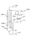
- FIG. 2 shows an example of a cooling tower used in the method for producing a conjugated diene of this embodiment.
- This cooling tower is an example having three sections, and a chimney 22A is provided in the middle stage.
- the chimney 22A is opened at the center, and a weir protruding upward is provided in the opening.
- the circulated water that has been circulated accumulates in a tray that is integrally installed on the chimney 22A and flows out to the circulation path.
- the circulating water that has flowed out is supplied to the heat exchanger 21A, cooled to a desired temperature, and then circulated for use. At this time, the water contained in the reaction product gas is condensed by being cooled in the cooling tower, and the liquid level in the chimney weir increases, so the liquid level is continuously withdrawn so as to keep the liquid level constant.
- the extracted water is sent to the section below the chimney (not shown), or a tank or the like (not shown) is installed in the middle of the liquid circulation channel to keep the liquid level in the tank constant. It may be extracted out of the system such as waste water treatment equipment.
- the high boiling point byproduct deposited on the cooling surface of the heat exchanger 21A can be removed by a known method. For example, scraping off the adhering matter on the cooling surface with a brush, washing with high pressure water, and heating and melting above the melting point of the adhering matter can be mentioned. Further, for example, it is possible to wash using an appropriate solvent. And if the high boiling point by-product accumulate
- the coolant is supplied to the cooling tower and brought into contact with the reaction product gas, and then the coolant discharged from the cooling tower is cooled by a cooler. Thereafter, the precipitate deposited by the cooling is collected by a separator, and the coolant after the collection of the precipitate is circulated to the cooling tower.
- the high-boiling by-product particularly 9-fluorenone, precipitates in the circulating water and is captured by the separation device in a suspended state in the circulating water.
- the cooling tower is the same as in the first invention. Water is preferred as the coolant. Although it does not specifically limit as a cooler in 2nd invention, A heat exchanger is preferable.
- the liquid linear velocity of the coolant passing through the heat exchanger is preferably higher than 1.0 m / sec (greater than 1.0 m / sec). More preferably, it is 1.5 m / sec or more, More preferably, it is 2.0 m / sec or more.
- the precipitated high boiling point by-product becomes difficult to adhere to the heat transfer surface in the heat exchanger, and the use time of the heat exchanger is further increased. be able to.
- the reaction product gas is cooled to 40 ° C. or lower in the cooling step, a cooling tower having two or more compartments is used as a cooling compartment, It is preferable to implement the method of 2.
- the above-mentioned separation device is also referred to as a high-boiling by-product separation device, and is installed to separate a high-boiling by-product described later.
- the number of separation devices is preferably 2 or more.
- the separation device include a screen, gravity sedimentation, gravity filtration, flotation, vacuum filtration, pressure filtration, cyclone, centrifugal sedimentator, and centrifugal filter.
- a screen and a centrifugal filter are preferable, and a screen is used more suitably.
- a strainer with a built-in screen is preferable.
- the separation device is a strainer with a built-in screen
- the screen is preferably 100 to 200 mesh, and the material may be metal or resin, preferably metal. In this way, 9-fluorenone can be removed particularly efficiently.
- the high boiling point by-product separated in the separation apparatus is a very small amount, the pressure loss of the separation apparatus does not increase remarkably, and it may be operated until regular periodic repair. In this case, the high boiling point by-product separated in the separator is removed when the operation is stopped.
- the high-boiling by-product precipitated is not attached to the heat exchanger, and is separated from the circulating water by the downstream separator.
- the high boiling point by-product can be separated from the place where the idea of separation is obtained.
- the concentration of high-boiling by-products deposited in the heat exchanger in the circulating water (coolant circulated in the cooling tower) varies depending on the amount of product produced in the reaction and the conditions of the cooling tower, but cannot be specified in general. According to the study by the present inventors, there is a tendency that contamination of the cooling tower can be efficiently prevented by setting the 9-fluorenone concentration in the circulating water (the coolant circulated to the cooling tower) to 30 wtppm or less.
- FIG. 4 shows an example of a cooling tower used in the method for producing a conjugated diene of this embodiment.
- This cooling tower is an example having three sections, and a chimney 22 is provided in the middle stage.
- the chimney 22 is opened at the center, and a weir protruding upward is provided in the opening.
- the circulated circulating water is collected on a tray installed integrally on the chimney 22 and flows out to the circulation path.
- the circulated water that has flowed out is supplied to the heat exchanger 21, cooled to a desired temperature, and then circulated for use.
- the water contained in the reaction product gas is condensed by being cooled in the cooling tower, and the liquid level in the chimney weir increases, so the liquid level is continuously withdrawn so as to keep the liquid level constant.
- the extracted water is sent to the section below the chimney (not shown), or a tank or the like (not shown) is installed in the middle of the liquid circulation channel to keep the liquid level in the tank constant. It may be extracted out of the system such as waste water treatment equipment.
- high-boiling by-products such as 9-fluorenone are precipitated as a solid in the circulating water.
- the circulating water containing the high boiling point by-product containing precipitated 9-fluorenone and the like exiting the heat exchanger 21 is separated into the circulating water and the high boiling point by-product containing precipitated 9-fluorenone and the like by the separation device 24A.
- the circulating water from which the high-boiling by-products containing precipitated 9-fluorenone and the like are separated is circulated to the cooling tower.
- the high boiling point by-product attached to the separation surface of the separation device 24A can be removed by a known method. Examples include scraping off the deposit on the separation surface with a brush, washing with high pressure water, or heating to a melting point higher than the melting point of the deposit. It is also possible to wash using an appropriate solvent.
- the circulating water flow path is changed to the separation device 24A, and the high boiling point by-products accumulated in the separation device 24B are removed.
- a plurality of high boiling point separators are sequentially switched and used, so that the high boiling point by-products generated by the reaction are separated and removed by the high boiling point separators without being deposited on the cooling surface of the heat exchanger. It is possible to prevent the cooling tower from becoming dirty, and the dirty material from flowing out into the subsequent process and hindering the operation.
- FIG. 1 is one embodiment of the process of the present invention.
- 1 shows a reactor
- 2 a gas cooling heat exchanger
- 3 a cooling tower
- 4 a compressor
- 5 an absorption tower
- 6 a degassing tower
- 7 a solvent separation tower.
- 2 and 3 are one embodiment of the cooling tower 3
- 20A, 20B, 30A and 30B indicate trays or packed beds
- 21A, 21B, 31A and 31B indicate heat exchangers
- 22A And 32 shows a chimney and 23 shows a water spray apparatus.
- reference numerals 100 to 111, 302, 303, and 310 denote pipes.
- FIG. 4 shows one of the embodiments of the cooling tower 3, wherein 20A and 20B indicate trays or packed beds, 21 indicates a heat exchanger, 22 indicates a chimney, 23 indicates a water spray device, 24A and 24B Indicates a separator (high boiling point by-product separator).
- reference numerals 102 to 103, 110, and 111 denote pipes.
- FIG. 1 shows a method for producing a conjugated diene using BBSS, which is a component discharged from a process of extracting and separating butadiene from a C4 fraction produced as a by-product in naphtha decomposition, as a raw material gas, and using butadiene as the resulting conjugated diene.
- a raw material n-butene or a mixture containing n-butene of the above-mentioned BBSS tower is gasified with a vaporizer (not shown), and nitrogen gas, air (molecular oxygen-containing gas), and water (steam) are mixed.
- the mixed gas is heated to about 150 to 400 ° C. by a preheater (not shown), and then supplied from a pipe 100 to a multitubular reactor 1 (oxidation dehydrogenation reactor) filled with a catalyst.
- the reaction product gas from the reactor 1 is extracted through the pipe 101, cooled by the gas cooling heat exchanger 2, and then introduced into the cooling tower 3 through the pipe 102 from the bottom of the tower.
- the product is dissolved in water and separated.
- the reaction gas after removing the high boiling point by-product is discharged from the pipe 103.
- the discharged gas is compressed by the compressor 4 and supplied to the absorption tower 5 and is brought into countercurrent contact with the absorbing solvent from the pipe 104.
- the conjugated diene and the unreacted raw material gas in the reaction product gas are absorbed by the absorption solvent.
- the component (off gas) that has not been absorbed by the absorbing solvent is extracted from the top of the absorption tower through the pipe 105, and at least a part thereof is circulated to the reactor. At this time, at least a part of the organic substance or carbon monoxide in the off gas may be converted to carbon dioxide and then recycled to the reactor.
- the absorption solvent in which the conjugated diene and the raw material gas are dissolved is extracted from the bottom of the absorption tower 5 and sent to the deaeration tower 6 through the pipe 106.
- oxygen, nitrogen, carbon dioxide and the like dissolved in a trace amount in the absorption solvent are gasified and removed.
- a condenser not shown
- the absorption solvent in which the conjugated diene extracted from the bottom of the deaeration tower and the raw material gas are dissolved is supplied to the solvent separation tower 7 via the pipe 108.
- the conjugated diene is distilled and a crude butadiene fraction is extracted from the top of the tower via a pipe 109.
- the separated absorption solvent is extracted from the bottom of the tower through the pipe 104 and is circulated as an absorption solvent for the absorption tower 5.
- impurities accumulated in the solvent are separated by a method such as distillation (not shown) and then circulated.
- the granular solid (ignition loss: 1.4% by weight) of the obtained catalyst precursor was pulverized, and 40.1 g of ammonium paramolybdate was dispersed in a solution obtained by adding 10 ml of ammonia water to 150 ml of pure water. Next, 0.85 g of borax and 0.36 g of potassium nitrate were dissolved in 40 ml of pure water under heating at 25 ° C. and added to the slurry.
- the catalyst calculated from the charged raw materials was a complex oxide having the following atomic ratio.
- Mo: Bi: Co: Ni: Fe: Na: B: K: Si 12: 5: 2.5: 2.5: 0.4: 0.35: 0.2: 0.08: 24
- the atomic ratios a1 and a2 of molybdenum at the time of preparation were 6.9 and 5.1, respectively.
- Example 1 309 ml of the composite oxide catalyst produced in Production Example 1 and an inert ball (manufactured by Tipton Corp.) per reaction tube in a reaction tube in the reactor 1 provided with 113 reaction tubes having an inner diameter of 27 mm and a length of 3500 mm. 398 ml was charged.
- the catalyst layer was composed of three layers, and the dilution rate of each layer was 80% by volume, 60% by volume, and 25% by volume from the inlet of the reactor toward the direction of the product gas outlet of the reactor.
- the raw material gases having the composition shown in Table 1 below, air, nitrogen and water vapor discharged from the C4 fraction by-produced by naphtha decomposition as raw material gases, air, nitrogen and water vapor, are respectively 15.9 Nm 3 / h, 87 supplied to .5Nm 3 /h,55.9Nm 3 / h and 17.7 nm 3 / h of preheater at a rate, after heating to 217 ° C., it was supplied from the raw material gas inlet to the multi-tubular reactor.
- a refrigerant with a temperature of 380 ° C. was flowed to the barrel side of the reactor to adjust the maximum temperature inside the reaction tube to 412 to 415 ° C.
- the product gas extracted from the reactor was supplied to the cooling tower, and the composition of the product gas was measured at the outlet of the cooling tower and was as shown in Table 2 below.
- the cooling tower is a 30-stage sieve tray tower with an inner diameter of 304 mm shown in FIG. 2, and a chimney is installed between the 20th and 21st stages from the top.
- the effluent gas from the top of the cooling tower was raised to 0.35 MPaG (showing gauge pressure; the same applies hereinafter) with a two-stage compressor 4 and sent to the absorption tower 5.
- a part of the effluent from the bottom of the cooling tower was circulated to the water spray device 23 at 1,000 kg / h. Furthermore, it was circulated to the lower stage of the chimney at 1,000 kg / h.
- the effluent from the chimney was sent to the heat exchanger 21A at 1,000 kg / h.
- the heat exchanger 21A is composed of 18 tubes each having an outer diameter of 19 mm, a thickness of 1.65 mm, and a length of 4 m. Circulating water is provided in the tubes, and cooling water at 5 ° C. is provided on the outer side (body side) of the tubes. Washed away.
- the circulating water inlet temperature of the heat exchanger 21A was 50 ° C., and the outlet temperature was adjusted with the amount of cooling water so as to be 25 ° C.
- the liquid linear velocity in the tube was 8 cm / sec (0.08 m / sec).
- the amount of cooling water in the heat exchanger 21A was 460 kg / h at the start of operation, but increased to 1,600 kg / h after two weeks, so the flow path was switched to the heat exchanger 21B having exactly the same structure as the heat exchanger 21A.
- the circulating water was cooled using the heat exchanger 21B and the operation was continued for 2 weeks. During this time, the heat exchanger 21A was opened, and the deposit adhered in the tube was cleaned with a brush.
- Example 2 One reaction tube having an inner diameter of 27 mm and a length of 6000 mm was charged with 309 ml of the composite oxide catalyst produced in Production Example 1 and 398 ml of inert balls (manufactured by Tipton Corp.). At this time, the catalyst layer was composed of three layers, and the dilution rate of each layer was 80% by volume, 60% by volume, and 25% by volume from the inlet of the reactor toward the direction of the product gas outlet of the reactor.
- the raw material gases having the composition shown in Table 1 and air, nitrogen and water vapor discharged from the butadiene extraction and separation process from the C4 fraction by-produced by naphtha decomposition as raw material gases are 0.14 Nm 3 / h, 0 were supplied to the mixer at a flow rate of .77Nm 3 /h,0.49Nm 3 / h and 0.16 nm 3 / h, after heating to 120 ° C., was supplied from the raw material gas inlet to the multi-tubular reactor.
- a refrigerant with a temperature of 380 ° C. was flowed to the barrel side of the reactor to adjust the maximum temperature inside the reaction tube to 412 to 415 ° C.
- the product gas extracted from the reactor was supplied to the cooling tower, and the composition of the product gas was measured at the outlet of the cooling tower.
- the cooling tower is a dual flow tray tower with an inner diameter of 54 mm and 19 stages shown in FIG. 3, and a chimney is installed between the 9th and 10th stages from the top.
- the effluent gas from the top of the cooling tower in FIG. 3 was sent to the flare.
- the effluent from the bottom of the cooling tower was circulated to the lower stage of the chimney at 12 kg / h.
- the effluent from the chimney was sent to the heat exchanger 31A at 12 kg / h, and 6 kg / h was sent to the heat exchanger 31B.
- the heat exchanger 31A is composed of one tube having an outer diameter of 10 mm, a thickness of 1 mm, and a length of 0.8 m. Circulating water is provided in the tube, and cooling water at 5 ° C. is provided on the outer side (body side) of the tube. Washed away.
- the circulating water inlet temperature of the heat exchanger 31 ⁇ / b> A was 70 ° C., and the outlet temperature was adjusted with the amount of cooling water so as to be 50 ° C.
- the liquid linear velocity in the tube of the heat exchanger 31A was 0.066 m / sec.
- the heat exchanger 31B is composed of one tube having an outer diameter of 10 mm, a thickness of 1 mm, and a length of 1.4 m. Circulating water is provided in the tube, and cooling water at 5 ° C. is provided on the outer side (body side) of the tube. Washed away.
- the circulating water inlet temperature of the heat exchanger 31B was 50 ° C., and the outlet temperature was adjusted with the amount of cooling water so as to be 30 ° C.
- the liquid linear velocity in the tube of the heat exchanger 31B was 0.033 m / sec.
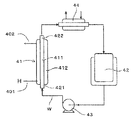
- the test heat exchanger 41 is a single-tube / double-tube heat exchanger using a test heat exchanger tube 411 having an outer diameter of 12.7 mm ⁇ , a thickness of 1.2 mm, and a length of 500 mm.
- a test heat exchanger tube 411 having an outer diameter of 12.7 mm ⁇ , a thickness of 1.2 mm, and a length of 500 mm.
- a SUS316 drawn tube was used as the vessel tube 411.
- the test heat exchanger shell 412 of the test heat exchanger 41 was manufactured with a pipe having an outer diameter of 34 mm ⁇ and a thickness of 3.4 mm, and a spiral baffle was provided inside.
- the circulating water of the cooling tower for confirming the effect of removing dirt was added to the water collected in the heat exchanger 21A in Example 1 at a concentration of 1,500 ppm to the water to form a slurry pipe W. Then, the slurry pipe W stored in the slurry tank 42 was fed to the test heat exchanger tube 411 side of the test heat exchanger 41 by the slurry circulation pump 43 and circulated to the slurry tank 42 via the reheater 44.
- the heat quantity Q [kcal / hr] is the flow rate Wc [kg / hr] of the cooling medium H (warm water), the specific heat C [kcal / (kg ⁇ K)] of the cooling medium H, and the cooling heat for the test heat exchanger 41.
- Wc the flow rate Wc [kg / hr] of the cooling medium H (warm water)
- C the specific heat C [kcal / (kg ⁇ K)] of the cooling medium H
- the logarithmic average temperature difference ⁇ t [K] is a temperature difference ⁇ t1 between the temperature of the inlet 401 of the cooling medium H and the temperature of the slurry outlet 422, and a temperature difference between the temperature of the outlet 402 of the cooling medium H and the temperature of the slurry inlet 421.
- ⁇ t ( ⁇ t1 ⁇ t2) / ln ( ⁇ t1 / ⁇ t2).
- FIG. 6 shows the relationship between the dirt resistance Rf and the liquid linear velocity.
- Example 1 The same operation as in Example 1 was performed except that the top temperature of the cooling tower 3 was adjusted to 45 ° C. by using 25 ° C. water as the cooling water of the heat exchanger 21A and the heat exchanger 21B.
- the first-stage discharge pressure of the compressor 4 has decreased to 0.3 MPaG
- the second-stage discharge pressure has decreased to 0.1 MPaG
- sufficient pressure to feed into the absorption tower 5 cannot be obtained. I had to stop.
- 9-fluorenone evaporates from the cooling tower 3 by raising the top temperature of the cooling tower 3, and the circulating water is cooled by a heat exchanger to produce high-boiling by-products such as 9-fluorenone. There was a need to precipitate and remove the material.
- Example 3 309 ml of the composite oxide catalyst produced in Production Example 1 and an inert ball (manufactured by Tipton Corp.) per reaction tube in a reaction tube in the reactor 1 provided with 113 reaction tubes having an inner diameter of 27 mm and a length of 3500 mm. 398 ml was charged.
- the catalyst layer was composed of three layers, and the dilution rate of each layer was 80% by volume, 60% by volume, and 25% by volume from the inlet of the reactor toward the direction of the product gas outlet of the reactor.
- the raw material gas having the composition shown in Table 1 discharged from the C4 fraction extracted and separated from the C4 fraction by-produced by naphtha cracking as the raw material gas, air, nitrogen and water vapor were 15.9 Nm 3 / h, 87, respectively. supplied to .5Nm 3 /h,55.9Nm 3 / h and 17.7 nm 3 / h of preheater at a rate, after heating to 217 ° C., it was supplied from the raw material gas inlet to the multi-tubular reactor.
- a refrigerant with a temperature of 380 ° C. was flowed to the barrel side of the reactor to adjust the maximum temperature inside the reaction tube to 412 to 415 ° C.
- the product gas extracted from the reactor was supplied to the cooling tower, and the composition of the product gas was measured at the outlet of the cooling tower and was as shown in Table 2 above.
- the cooling tower is a 30-stage sieve tray tower with an inner diameter of 304 mm shown in FIG. 4, and a chimney is installed between the 20th and 21st stages from the top.
- the outflow gas from the top of the cooling tower was boosted to 0.35 MPaG with a two-stage reciprocating compressor 4 and sent to the absorption tower 5.
- a part of the effluent from the bottom of the cooling tower was circulated to the water spray device 23 at 1,000 kg / h. Furthermore, it was circulated to the lower stage of the chimney at 1,000 kg / h.
- the effluent from the chimney was sent to the heat exchanger 21 at 1,500 kg / h.
- the heat exchanger 21 is composed of two tubes each having an outer diameter of 19 mm, a thickness of 1.65 mm, and a length of 4 m. Circulating water is provided in the tube, and cooling water at 5 ° C. is provided on the outer side (body side) of the tube. Washed away.
- the circulating water inlet temperature of the heat exchanger 21 was adjusted to 50 ° C., and the outlet temperature was adjusted to 25 ° C. with the amount of cooling water.
- the liquid linear velocity in the tube was 1.08 m / sec.
- the circulating water cooled by the heat exchanger and containing the precipitate was sent to the separation device 24A.
- the separation device 24A was a strainer incorporating a SUS 200 mesh screen.
- the operation was continued by switching to the separator 24B having the same specifications as the separator 24A.
- the separation device 24A was opened, and the deposits accumulated in the strainer were cleaned with a brush. Thereafter, the switching operation of the separation devices 24A and 24B was performed for about one week for two months.
- the concentration of 9-fluorenone in the circulating water was 17 wtppm, and the top temperature of the cooling tower remained constant at 25 ° C.
- the first-stage discharge pressure of the compressor 4 was stable at 0.15 MPaG, and the second-stage discharge pressure was 0.35 MPaG.
- the weight of the precipitate collected by cleaning the separators 24A and 24B was 218 g / 1 week on average.
- Example 2 The same operation as in Example 3 was performed except that neither the separation device 24A nor 24B was used, and the circulating water from the heat exchanger 21 was returned to the cooling tower as it was. Immediately after the start of operation, the opening degree of a control valve (not shown) for controlling the flow rate of 1,500 kg / h of circulating water flowing out from the chimney and circulating through the heat exchanger to the cooling tower gradually increases. (Not shown) is fully open.
- the heat exchanger 31B was a tube having an outer diameter of 4 mm, a thickness of 1 mm, and a length of 5.7 m, and the same operation as in Example 2 was performed except that the internal liquid linear velocity was 1.06 m / sec. After operating the heat exchangers 31A and 31B for 144 hours, the heat exchanger 31B was opened, and the deposit adhered in the tube was cleaned with a brush. 9-fluorenone was not deposited on the heat exchanger 31B, and 9-fluorenone was deposited on the pipe 303.
Landscapes
- Chemical & Material Sciences (AREA)
- Organic Chemistry (AREA)
- Engineering & Computer Science (AREA)
- Analytical Chemistry (AREA)
- Oil, Petroleum & Natural Gas (AREA)
- Water Supply & Treatment (AREA)
- Materials Engineering (AREA)
- Chemical Kinetics & Catalysis (AREA)
- Crystallography & Structural Chemistry (AREA)
- Organic Low-Molecular-Weight Compounds And Preparation Thereof (AREA)
- Low-Molecular Organic Synthesis Reactions Using Catalysts (AREA)
- Catalysts (AREA)
Abstract
Description
[1]触媒存在下、炭素原子数4以上のモノオレフィンを含む原料ガスを分子状酸素含有ガスにより酸化脱水素反応させて共役ジエンを含む反応生成ガスを得る反応工程と、前記反応生成ガスを冷却する冷却工程とを有する共役ジエンの製造方法であって、
前記冷却工程では、冷却剤を冷却塔に供給し反応生成ガスと接触させた後、前記冷却塔から排出された冷却剤を熱交換器により冷却して、前記冷却剤中に溶存した析出物を前記熱交換器内に析出させて回収し、前記析出物回収後の冷却剤を前記冷却塔に循環させる、
共役ジエンの製造方法。
[2]前記冷却剤が水である前記[1]に記載の共役ジエンの製造方法。
[3]前記析出物が9-フルオレノンである前記[1]又は[2]に記載の共役ジエンの製造方法。
[4]前記熱交換器が2以上である前記[1]から[3]のいずれか1に記載の共役ジエンの製造方法。
[5]前記熱交換器が並列及び直列の少なくとも一方に並んでいる前記[4]に記載の共役ジエンの製造方法。
[6]前記析出物を析出させる熱交換器における液線速が1.0m/秒以下である前記[1]から[5]のいずれか1に記載の共役ジエンの製造方法。
[7]前記冷却塔に循環させる冷却剤中の9-フルオレノンの濃度が30wtppm以下である前記[3]から[6]のいずれか1に記載の共役ジエンの製造方法。
[8]前記原料ガスが、エチレンの2量化により得られる1-ブテン、シス-2-ブテン若しくはトランス-2-ブテン又はこれらの混合物を含有するガス、n-ブタンの脱水素又は酸化脱水素反応により生成するブテン留分、あるいは重油留分を流動接触分解する際に得られる炭素原子数が4の炭化水素を含むガスである前記[1]から[7]の何れか1に記載の共役ジエンの製造方法。
[9]触媒存在下、炭素原子数4以上のモノオレフィンを含む原料ガスを分子状酸素含有ガスにより酸化脱水素反応させて共役ジエンを含む反応生成ガスを得る反応工程と、前記反応生成ガスを冷却する冷却工程とを有する共役ジエンの製造方法であって、
前記冷却工程では、前記冷却剤を冷却塔に供給し反応生成ガスと接触させた後、前記冷却塔から排出された冷却剤を冷却器により冷却した後、前記冷却により析出した析出物を分離装置により回収し、前記析出物回収後の冷却剤を前記冷却塔に循環させる、
共役ジエンの製造方法。
[10]前記冷却剤が水である前記[9]に記載の共役ジエンの製造方法。
[11]前記析出物が9-フルオレノンである前記[9]又は[10]に記載の共役ジエンの製造方法。
[12]前記分離装置が2以上である前記[9]から[11]のいずれか1に記載の共役ジエンの製造方法。
[13]前記冷却器が熱交換器であり、前記冷却器における液線速が1.0m/秒より速い前記[9]から[12]のいずれか1に記載の共役ジエンの製造方法。
[14]前記冷却塔に循環させる冷却剤中の9-フルオレノン濃度が30wtppm以下である前記[11]から[13]のいずれか1に記載の共役ジエンの製造方法。
[15]前記原料ガスが、エチレンの2量化により得られる1-ブテン、シス-2-ブテン、トランス-2-ブテン若しくはこれらの混合物を含有するガス、n-ブタンの脱水素若しくは酸化脱水素反応により生成するブテン留分、又は重油留分を流動接触分解する際に得られる炭素原子数が4の炭化水素を含むガスである前記[9]から[14]の何れか1に記載の共役ジエンの製造方法。
[16]触媒存在下、炭素原子数4以上のモノオレフィンを含む原料ガスを分子状酸素含有ガスにより酸化脱水素反応させて共役ジエンを含む反応生成ガスを得る反応工程と、前記反応生成ガスを冷却する冷却工程とを有する共役ジエンの製造方法であって、
前記冷却工程では、水を冷却剤とし、
前記冷却剤を冷却塔に供給し反応生成ガスと接触させた後、前記冷却塔から排出された冷却剤を熱交換器により冷却して前記冷却塔に循環させるに際し、
前記熱交換器を通過する前記冷却剤の液線速を1.0m/秒以下として前記熱交換器内に9-フルオレノンを堆積させることにより前記冷却剤から9-フルオレノンを分離すること、又は前記熱交換器を通過する前記冷却剤の液線速を1.0m/秒より速くして前記熱交換器を通過した後に分離装置により前記冷却剤から9-フルオレノンを分離すること、を特徴とする共役ジエンの製造方法。
[17]前記冷却塔に循環させる冷却剤中の9-フルオレノン濃度が30wtppm以下である前記[16]に記載の共役ジエンの製造方法。
[18]前記原料ガスが、エチレンの2量化により得られる1-ブテン、シス-2-ブテン若しくはトランス-2-ブテン又はこれらの混合物を含有するガス、n-ブタンの脱水素又は酸化脱水素反応により生成するブテン留分、あるいは重油留分を流動接触分解する際に得られる炭素原子数が4の炭化水素を含むガスであることを特徴とする前記[16]又は[17]に記載の共役ジエンの製造方法。
本発明では、炭素原子数4以上のモノオレフィンを含む原料ガスと分子状酸素含有ガスとを触媒層を有する反応器に供給し、酸化脱水素反応により対応する共役ジエンを製造する。
本発明の原料ガスは、炭素原子数4以上のモノオレフィンを含む。炭素原子数4以上のモノオレフィンとしては、例えば、ブテン(例えば、1-ブテン及び2-ブテン等のn-ブテン、並びにイソブテン)、ペンテン、メチルブテン及びジメチルブテン等の炭素原子数4以上、好ましくは炭素原子数4~6のモノオレフィンが挙げられ、接触酸化脱水素反応による対応する共役ジエンの製造に有効に適用することができる。この中でも、n-ブテン(例えば、1-ブテン及び2-ブテン等のn-ブテン)からのブタジエンの製造に最も好適に用いられる。
次に、本発明で好適に用いられる酸化脱水素反応触媒について説明する。本発明で用いる酸化脱水素触媒は、少なくともモリブデン、ビスマス及びコバルトを含有する複合酸化物触媒であることが好ましい。そして、この中でも、下記一般式(1)で表される複合酸化物触媒であることがより好ましい。
なお、式中、Xはマグネシウム(Mg)、カルシウム(Ca)、亜鉛(Zn)、セリウム(Ce)及びサマリウム(Sm)からなる群から選ばれる少なくとも1種の元素である。Yはナトリウム(Na)、カリウム(K)、ルビジウム(Rb)、セシウム(Cs)及びタリウム(Tl)からなる群から選ばれる少なくとも1種の元素である。Zはホウ素(B)、リン(P)、砒素(As)及びタングステン(W)からなる群から選ばれる少なくとも1種の元素である。
灼熱減量(%)=[(W0-W1)/W0]×100
・W0:触媒前駆体を150℃で3時間乾燥して付着水分を除いたものの重量(g)。
・W1:付着水分を除いた前記触媒前駆体を更に500℃で2時間熱処理した後の重量(g)。
本発明の分子状酸素含有ガスとは、分子状酸素が、通常10容量%以上、好ましくは15容量%以上、更に好ましくは20容量%以上含まれるガスのことであり、具体的に好ましくは空気である。なお、分子状酸素含有ガスを工業的に用意するのに必要なコストが増加するという観点から、分子状酸素の含有量の上限としては、通常50容量%以下であり、好ましくは30容量%以下、更に好ましくは25容量%以下である。また、本発明の効果を阻害しない範囲で、分子状酸素含有ガスには、任意の不純物を含んでいてもよい。
本発明では、反応器に原料ガスを供給するにあたり、原料ガスと分子状酸素含有ガスとを混合し、その混合されたガス(以下、「混合ガス」呼ぶことがある)を反応器に供給する必要がある。なお、本発明の混合ガス中の、原料ガスの割合としては、通常3.0容量%以上であり、好ましくは5.0容量%以上、更に好ましくは6.0容量%以上である。この下限値が大きくなるほど、反応器のサイズを小さくでき、建設費および運転に要するコストが低減する傾向にある。また、一方、上限は、通常25.0容量%以下であり、好ましくは20.0容量%以下、更に好ましくは18.0容量%以下である。この上限値が小さくなるほど、高沸点副生成物の生成が減少する傾向があり好ましい。
本発明の酸化脱水素反応に用いられる反応器は特に限定されないが、具体的には、例えば、管型反応器、槽型反応器及び流動床反応器が挙げられる。好ましくは固定床反応器であり、より好ましくは固定床の多管式反応器やプレート式反応器であり、最も好ましくは固定床の多管式反応器である。
本発明の酸化脱水素反応は発熱反応であり、反応により温度が上昇するが、本発明では、通常、反応温度は通常250~450℃、好ましくは320~420℃の範囲に調整される。この温度が大きくなるほど、触媒活性が急激に低下しやすい傾向にあり、小さくなるほど、目的生成物である共役ジエンの収率が低下する傾向にある。反応温度は、熱媒体(例えば、ジベンジルトルエン及び亜硝酸塩など)を使用して制御することができる。なお、ここでいう反応温度は熱媒体の温度のことのことである。
本発明における第1の発明について説明する。第1の発明では、上記反応工程で得られた反応生成ガスを冷却する冷却工程を有するが、前記冷却工程では、冷却剤を冷却塔に供給し反応生成ガスと接触させた後、前記冷却塔から排出された冷却剤を熱交換器により冷却して、前記冷却剤中に溶存した析出物を前記熱交換器内に析出させて回収し、前記析出物回収後の冷却剤を前記冷却塔に循環させる。冷却剤としては、水が好ましい。
本発明の冷却塔は、冷却剤を用いて反応生成ガスを急速に冷却することを目的としている。そのため、本発明の冷却塔は、急冷塔又はクエンチ塔と称することがある。また、冷却剤を急冷剤と称することもある。
以下に、図面を参照して、本発明の共役ジエンの製造方法に関するプロセスの実施形態について、ブタジエンを製造する例を挙げて説明する。
パラモリブデン酸アンモニウム54gを純水250mlに70℃に加温して溶解させた。次に、硝酸第二鉄7.18g、硝酸コバルト31.8g及び硝酸ニッケル31.8gを純水60mlに70℃に加温して溶解させた。これらの溶液を、充分に撹拌しながら徐々に混合した。
Mo:Bi:Co:Ni:Fe:Na:B:K:Si=12:5:2.5:2.5:0.4:0.35:0.2:0.08:24
また、調製の際のモリブデンの原子比a1とa2は、それぞれ6.9と5.1であった。
内径27mm、長さ3500mmの反応管を113本備えた反応器1内の反応管に、反応管1本当たり、製造例1で製造された複合酸化物触媒309mlとイナートボール(Tipton Corp.製)398mlとを充填した。このとき触媒層は3層で構成されており、各層の希釈率は反応器の入口から反応器の生成ガス出口の方向に向かって、80体積%、60体積%、25体積%であった。


内径27mm、長さ6000mmの反応管1本に、製造例1で製造された複合酸化物触媒309mlとイナートボール(Tipton Corp.製)398mlとを充填した。このとき触媒層は3層で構成されており、各層の希釈率は反応器の入口から反応器の生成ガス出口の方向に向かって、80体積%、60体積%、25体積%であった。
水を冷却剤として用い、該冷却剤を熱交換器により冷却して冷却塔に循環させる上記実施例において、熱交換器を通過する冷却剤の液線速と、冷却剤に含まれる高沸点副生成物の熱交換器冷却伝面への析出(冷却伝面の汚れ)との関係を検証するため、以下の試験を行った。

熱交換器21A、熱交換器21Bの冷却水として25℃の水を用いることで冷却塔3の塔頂温度を45℃に調整した他は実施例1と同じく操作した。2週間を経過した所で圧縮機4の1段吐出圧が0.3MPaG、2段吐出圧が0.1MPaGまで低下し、吸収塔5に送入するのに十分な圧力が得られず運転を停止せざるを得なかった。
内径27mm、長さ3500mmの反応管を113本備えた反応器1内の反応管に、反応管1本当たり、製造例1で製造された複合酸化物触媒309mlとイナートボール(Tipton Corp.製)398mlとを充填した。このとき触媒層は3層で構成されており、各層の希釈率は反応器の入口から反応器の生成ガス出口の方向に向かって、80体積%、60体積%、25体積%であった。
図4に示すチムニー22から抜き出した循環水111に、分離装置24Aから回収した9-フルオレノン等を含む高沸点副生成物を100ppmの濃度で添加しスラリー液を調製した。このスラリー液を、遠心ろ過器(三陽理化学器械製作所製、型式:SYK-3800、ろ紙(アドバンテック製、品番:No.4A)を装着)に約50ml入れて、回転数調整目盛(0~5まで調整可能、最高回転数4500rpm)を2として遠心ろ過を行った。この遠心ろ過器から流出したろ液を回収し分析した結果、9-フルオレノンの濃度は19wtppmであり、高沸点物分離装置を遠心ろ過器とすることができることが示された。
実施例3において熱交換器21より回収された析出物を1,500ppmの濃度で水に添加しスラリー配管Wとした以外、参考例1~5と同様に実施した。

分離装置24Aも24Bも使用せず、熱交換器21から出た循環水をそのまま冷却塔に戻した以外は、実施例3と同じ操作とした。運転開始直後から、チムニーから流出し熱交換器を経て冷却塔に循環される循環水の流量1,500kg/hを制御する制御弁(図示せず)の開度が次第に大きくなり、制御弁(図示せず)の開度が全開となった。
熱交換器31Bを外径4mm、厚さ1mm、長さ5.7mのチューブとし、内液線速は1.06m/秒とした以外は実施例2と同じ操作とした。熱交換器31A、31Bを144hr稼働させた後に熱交換器31Bを開放し、チューブ内に付着した析出物をブラシで掃除した。熱交換器31Bに9-フルオレノンは析出せず、配管303に9-フルオレノンが析出していた。
2 ガス冷却熱交換器
3 冷却塔
4 圧縮機
5 吸収塔
6 脱気塔
7 溶媒分離塔
20A、20B トレイまたは充填層
21、21A、21B 熱交換器
22、22A チムニー
23 水噴霧装置
24A、24B 分離装置
30A、30B トレイまたは充填層
31A、31B 熱交換器(単管)
32 チムニー(単管)
41 テスト用熱交換器
42 スラリータンク
43 スラリー循環ポンプ
44 再加熱器
100~111、302~310 配管
401 テスト用冷熱媒体入口配管
402 テスト用冷熱媒体出口配管
411 テスト用熱交換器チューブ
412 テスト用熱交換器シェル
421 スラリー入口
422 スラリー出口
W スラリー配管
Claims (18)
- 触媒存在下、炭素原子数4以上のモノオレフィンを含む原料ガスを分子状酸素含有ガスにより酸化脱水素反応させて共役ジエンを含む反応生成ガスを得る反応工程と、前記反応生成ガスを冷却する冷却工程とを有する共役ジエンの製造方法であって、
前記冷却工程では、冷却剤を冷却塔に供給し反応生成ガスと接触させた後、前記冷却塔から排出された冷却剤を熱交換器により冷却して、前記冷却剤中に溶存した析出物を前記熱交換器内に析出させて回収し、前記析出物回収後の冷却剤を前記冷却塔に循環させる、
共役ジエンの製造方法。 - 前記冷却剤が水である請求項1に記載の共役ジエンの製造方法。
- 前記析出物が9-フルオレノンである請求項1又は2に記載の共役ジエンの製造方法。
- 前記熱交換器が2以上である請求項1から3のいずれか1項に記載の共役ジエンの製造方法。
- 前記熱交換器が並列及び直列の少なくとも一方に並んでいる請求項4に記載の共役ジエンの製造方法。
- 前記析出物を析出させる熱交換器における液線速が1.0m/秒以下である請求項1から5のいずれか1項に記載の共役ジエンの製造方法。
- 前記冷却塔に循環させる冷却剤中の9-フルオレノンの濃度が30wtppm以下である請求項3から6のいずれか1項に記載の共役ジエンの製造方法。
- 前記原料ガスが、エチレンの2量化により得られる1-ブテン、シス-2-ブテン若しくはトランス-2-ブテン又はこれらの混合物を含有するガス、n-ブタンの脱水素又は酸化脱水素反応により生成するブテン留分、あるいは重油留分を流動接触分解する際に得られる炭素原子数が4の炭化水素を含むガスである請求項1から7の何れか1項に記載の共役ジエンの製造方法。
- 触媒存在下、炭素原子数4以上のモノオレフィンを含む原料ガスを分子状酸素含有ガスにより酸化脱水素反応させて共役ジエンを含む反応生成ガスを得る反応工程と、前記反応生成ガスを冷却する冷却工程とを有する共役ジエンの製造方法であって、
前記冷却工程では、前記冷却剤を冷却塔に供給し反応生成ガスと接触させた後、前記冷却塔から排出された冷却剤を冷却器により冷却した後、前記冷却により析出した析出物を分離装置により回収し、前記析出物回収後の冷却剤を前記冷却塔に循環させる、
共役ジエンの製造方法。 - 前記冷却剤が水である請求項9に記載の共役ジエンの製造方法。
- 前記析出物が9-フルオレノンである請求項9又は10に記載の共役ジエンの製造方法。
- 前記分離装置が2以上である請求項9から11のいずれか1項に記載の共役ジエンの製造方法。
- 前記冷却器が熱交換器であり、前記冷却器における液線速が1.0m/秒より速い請求項9から12のいずれか1項に記載の共役ジエンの製造方法。
- 前記冷却塔に循環させる冷却剤中の9-フルオレノン濃度が30wtppm以下である請求項11から13のいずれか1項に記載の共役ジエンの製造方法。
- 前記原料ガスが、エチレンの2量化により得られる1-ブテン、シス-2-ブテン、トランス-2-ブテン若しくはこれらの混合物を含有するガス、n-ブタンの脱水素若しくは酸化脱水素反応により生成するブテン留分、又は重油留分を流動接触分解する際に得られる炭素原子数が4の炭化水素を含むガスである請求項9から14の何れか1項に記載の共役ジエンの製造方法。
- 触媒存在下、炭素原子数4以上のモノオレフィンを含む原料ガスを分子状酸素含有ガスにより酸化脱水素反応させて共役ジエンを含む反応生成ガスを得る反応工程と、前記反応生成ガスを冷却する冷却工程とを有する共役ジエンの製造方法であって、
前記冷却工程では、水を冷却剤とし、
前記冷却剤を冷却塔に供給し反応生成ガスと接触させた後、前記冷却塔から排出された冷却剤を熱交換器により冷却して前記冷却塔に循環させるに際し、
前記熱交換器を通過する前記冷却剤の液線速を1.0m/秒以下として前記熱交換器内に9-フルオレノンを堆積させることにより前記冷却剤から9-フルオレノンを分離すること、又は前記熱交換器を通過する前記冷却剤の液線速を1.0m/秒より速くして前記熱交換器を通過した後に分離装置により前記冷却剤から9-フルオレノンを分離すること、を特徴とする共役ジエンの製造方法。 - 前記冷却塔に循環させる冷却剤中の9-フルオレノン濃度が30wtppm以下である請求項16に記載の共役ジエンの製造方法。
- 前記原料ガスが、エチレンの2量化により得られる1-ブテン、シス-2-ブテン若しくはトランス-2-ブテン又はこれらの混合物を含有するガス、n-ブタンの脱水素又は酸化脱水素反応により生成するブテン留分、あるいは重油留分を流動接触分解する際に得られる炭素原子数が4の炭化水素を含むガスであることを特徴とする請求項16又は17に記載の共役ジエンの製造方法。
Priority Applications (6)
| Application Number | Priority Date | Filing Date | Title |
|---|---|---|---|
| RU2017131411A RU2703514C2 (ru) | 2015-03-09 | 2016-03-08 | Способ получения сопряженного диена |
| ES16761751T ES2848120T3 (es) | 2015-03-09 | 2016-03-08 | Proceso para la producción de dieno conjugado |
| EP16761751.3A EP3269697B1 (en) | 2015-03-09 | 2016-03-08 | Process for producing conjugated diene |
| KR1020177024971A KR102472467B1 (ko) | 2015-03-09 | 2016-03-08 | 공액 디엔의 제조 방법 |
| CN201680014346.4A CN107428637B (zh) | 2015-03-09 | 2016-03-08 | 共轭二烯的制造方法 |
| US15/699,666 US10370309B2 (en) | 2015-03-09 | 2017-09-08 | Method for producing conjugated diene |
Applications Claiming Priority (4)
| Application Number | Priority Date | Filing Date | Title |
|---|---|---|---|
| JP2015-046057 | 2015-03-09 | ||
| JP2015046057 | 2015-03-09 | ||
| JP2015056589 | 2015-03-19 | ||
| JP2015-056589 | 2015-03-19 |
Related Child Applications (1)
| Application Number | Title | Priority Date | Filing Date |
|---|---|---|---|
| US15/699,666 Continuation US10370309B2 (en) | 2015-03-09 | 2017-09-08 | Method for producing conjugated diene |
Publications (1)
| Publication Number | Publication Date |
|---|---|
| WO2016143783A1 true WO2016143783A1 (ja) | 2016-09-15 |
Family
ID=56880107
Family Applications (1)
| Application Number | Title | Priority Date | Filing Date |
|---|---|---|---|
| PCT/JP2016/057162 WO2016143783A1 (ja) | 2015-03-09 | 2016-03-08 | 共役ジエンの製造方法 |
Country Status (8)
| Country | Link |
|---|---|
| US (1) | US10370309B2 (ja) |
| EP (1) | EP3269697B1 (ja) |
| JP (1) | JP2016172721A (ja) |
| KR (1) | KR102472467B1 (ja) |
| CN (1) | CN107428637B (ja) |
| ES (1) | ES2848120T3 (ja) |
| RU (1) | RU2703514C2 (ja) |
| WO (1) | WO2016143783A1 (ja) |
Families Citing this family (6)
| Publication number | Priority date | Publication date | Assignee | Title |
|---|---|---|---|---|
| CN107941039B (zh) * | 2016-10-12 | 2020-03-03 | 英尼奥斯欧洲股份公司 | 骤冷塔后冷却器 |
| KR102064316B1 (ko) | 2016-12-29 | 2020-01-09 | 주식회사 엘지화학 | 부타디엔 제조방법 |
| CA2988462A1 (en) * | 2017-12-11 | 2019-06-11 | Nova Chemicals Corporation | Method for removing fouling downstream of an odh reactor |
| ZA201807242B (en) * | 2017-12-21 | 2019-07-31 | Indian Oil Corp Ltd | An integrated fluid catalytic cracking and oxidative propane dehydrogenation process |
| WO2019168276A1 (ko) * | 2018-02-27 | 2019-09-06 | 주식회사 엘지화학 | 1,3-부타디엔의 제조방법 |
| CN110787524A (zh) * | 2019-11-08 | 2020-02-14 | 协鑫高科纳米新材料(徐州)有限公司 | 一种气相二氧化硅生产用的分离器 |
Citations (9)
| Publication number | Priority date | Publication date | Assignee | Title |
|---|---|---|---|---|
| JPS5731637A (en) * | 1980-07-30 | 1982-02-20 | Yoshio Yokoyama | Preparation of anthraquinone |
| JPH111454A (ja) * | 1997-04-16 | 1999-01-06 | Mitsubishi Chem Corp | ジアセトキシブテンの製造方法 |
| JP2011006381A (ja) * | 2009-05-29 | 2011-01-13 | Mitsubishi Chemicals Corp | 共役ジエンの製造方法 |
| JP2011132218A (ja) * | 2009-11-27 | 2011-07-07 | Mitsubishi Chemicals Corp | 共役ジエンの製造方法 |
| JP2013119530A (ja) * | 2011-12-07 | 2013-06-17 | Mitsubishi Chemicals Corp | 共役ジエンの製造方法 |
| JP2013177380A (ja) * | 2012-02-08 | 2013-09-09 | Mitsubishi Chemicals Corp | 共役ジエンの製造方法 |
| JP2013213028A (ja) * | 2012-03-07 | 2013-10-17 | Mitsubishi Chemicals Corp | 共役ジエンの製造方法 |
| WO2014086813A1 (de) * | 2012-12-06 | 2014-06-12 | Basf Se | Verfahren zur oxidativen dehydrierung von n-butenen zu butadien |
| WO2014111406A1 (de) * | 2013-01-15 | 2014-07-24 | Basf Se | Verfahren zur oxidativen dehydrierung von n-butenen zu butadien |
Family Cites Families (11)
| Publication number | Priority date | Publication date | Assignee | Title |
|---|---|---|---|---|
| JPS60115531A (ja) | 1983-11-25 | 1985-06-22 | Nippon Zeon Co Ltd | ブタジエンの製造法 |
| JPS615030A (ja) | 1984-06-18 | 1986-01-10 | Japan Synthetic Rubber Co Ltd | ブタジエン−1,3の精製法 |
| SU1417409A1 (ru) * | 1986-10-02 | 1999-12-20 | Р.С. Муллина | Способ получения бутадиена |
| EP0872472B1 (en) | 1997-04-16 | 2001-08-16 | Mitsubishi Chemical Corporation | Process for producing diacetoxybutene |
| JP5621304B2 (ja) | 2009-05-21 | 2014-11-12 | 三菱化学株式会社 | 共役ジエンの製造方法 |
| KR20120026049A (ko) * | 2009-05-29 | 2012-03-16 | 미쓰비시 가가꾸 가부시키가이샤 | 공액 디엔의 제조 방법 |
| JP5767795B2 (ja) | 2010-09-27 | 2015-08-19 | 旭化成ケミカルズ株式会社 | ブタジエンの製造方法 |
| PL2711350T3 (pl) | 2011-05-19 | 2018-02-28 | Asahi Kasei Kabushiki Kaisha | Sposób wytwarzania 1,3-butadienu |
| JP6187334B2 (ja) | 2013-03-13 | 2017-08-30 | 三菱ケミカル株式会社 | 共役ジエンの製造方法 |
| KR101603380B1 (ko) * | 2013-05-06 | 2016-03-15 | 주식회사 엘지화학 | 공액디엔계 화합물의 제조방법 |
| WO2015007841A1 (de) * | 2013-07-18 | 2015-01-22 | Basf Se | Verfahren zur oxidativen dehydrierung von n-butenen zu 1,3-butadien |
-
2016
- 2016-03-08 WO PCT/JP2016/057162 patent/WO2016143783A1/ja active Application Filing
- 2016-03-08 EP EP16761751.3A patent/EP3269697B1/en active Active
- 2016-03-08 JP JP2016044238A patent/JP2016172721A/ja active Pending
- 2016-03-08 KR KR1020177024971A patent/KR102472467B1/ko active IP Right Grant
- 2016-03-08 CN CN201680014346.4A patent/CN107428637B/zh active Active
- 2016-03-08 ES ES16761751T patent/ES2848120T3/es active Active
- 2016-03-08 RU RU2017131411A patent/RU2703514C2/ru active
-
2017
- 2017-09-08 US US15/699,666 patent/US10370309B2/en active Active
Patent Citations (9)
| Publication number | Priority date | Publication date | Assignee | Title |
|---|---|---|---|---|
| JPS5731637A (en) * | 1980-07-30 | 1982-02-20 | Yoshio Yokoyama | Preparation of anthraquinone |
| JPH111454A (ja) * | 1997-04-16 | 1999-01-06 | Mitsubishi Chem Corp | ジアセトキシブテンの製造方法 |
| JP2011006381A (ja) * | 2009-05-29 | 2011-01-13 | Mitsubishi Chemicals Corp | 共役ジエンの製造方法 |
| JP2011132218A (ja) * | 2009-11-27 | 2011-07-07 | Mitsubishi Chemicals Corp | 共役ジエンの製造方法 |
| JP2013119530A (ja) * | 2011-12-07 | 2013-06-17 | Mitsubishi Chemicals Corp | 共役ジエンの製造方法 |
| JP2013177380A (ja) * | 2012-02-08 | 2013-09-09 | Mitsubishi Chemicals Corp | 共役ジエンの製造方法 |
| JP2013213028A (ja) * | 2012-03-07 | 2013-10-17 | Mitsubishi Chemicals Corp | 共役ジエンの製造方法 |
| WO2014086813A1 (de) * | 2012-12-06 | 2014-06-12 | Basf Se | Verfahren zur oxidativen dehydrierung von n-butenen zu butadien |
| WO2014111406A1 (de) * | 2013-01-15 | 2014-07-24 | Basf Se | Verfahren zur oxidativen dehydrierung von n-butenen zu butadien |
Non-Patent Citations (1)
| Title |
|---|
| See also references of EP3269697A4 * |
Also Published As
| Publication number | Publication date |
|---|---|
| CN107428637B (zh) | 2021-06-25 |
| US20170369400A1 (en) | 2017-12-28 |
| RU2703514C2 (ru) | 2019-10-18 |
| CN107428637A (zh) | 2017-12-01 |
| JP2016172721A (ja) | 2016-09-29 |
| ES2848120T3 (es) | 2021-08-05 |
| KR102472467B1 (ko) | 2022-11-30 |
| EP3269697A4 (en) | 2018-03-21 |
| US10370309B2 (en) | 2019-08-06 |
| RU2017131411A3 (ja) | 2019-05-07 |
| RU2017131411A (ru) | 2019-04-09 |
| EP3269697A1 (en) | 2018-01-17 |
| EP3269697B1 (en) | 2021-01-06 |
| KR20170128271A (ko) | 2017-11-22 |
Similar Documents
| Publication | Publication Date | Title |
|---|---|---|
| WO2016143783A1 (ja) | 共役ジエンの製造方法 | |
| JP5621304B2 (ja) | 共役ジエンの製造方法 | |
| JP5648319B2 (ja) | 共役ジエンの製造方法 | |
| JP5621305B2 (ja) | 共役ジエンの製造方法 | |
| JP5780072B2 (ja) | 共役ジエンの製造方法 | |
| JP2010090083A (ja) | 共役ジエンの製造方法 | |
| JP5652151B2 (ja) | 共役ジエンの製造方法 | |
| RU2415126C2 (ru) | Способ снижения температуры горячей точки неподвижного слоя катализатора в процессе получения акриловой кислоты путем двухстадийного способа гетерогенно катализируемого частичного окисления в газовой фазе пропилена | |
| JP2010090082A (ja) | 共役ジエンの製造方法 | |
| JP2013119530A (ja) | 共役ジエンの製造方法 | |
| JP2012240963A (ja) | 共役ジエンの製造方法 | |
| JP2010280653A (ja) | 共役ジエンの製造方法 | |
| JP2011132218A (ja) | 共役ジエンの製造方法 | |
| JP5682130B2 (ja) | 共役ジエンの製造方法 | |
| JP2012106942A (ja) | 共役ジエンの製造方法 | |
| JP2012111751A (ja) | 共役ジエンの製造方法 | |
| JP2013213028A (ja) | 共役ジエンの製造方法 | |
| JP6187334B2 (ja) | 共役ジエンの製造方法 | |
| JP5780069B2 (ja) | 共役ジエンの製造方法 | |
| JP5780038B2 (ja) | 共役ジエンの製造方法 | |
| JP2011148764A (ja) | 共役ジエンの製造方法 | |
| JP2012111699A (ja) | 共役ジエンの製造方法 | |
| JP6405857B2 (ja) | 共役ジエンの製造方法 | |
| JP7207295B2 (ja) | 接触酸化方法、酸化脱水素反応生成物の製造方法、及び酸化反応生成物の製造方法 | |
| JP2014177417A (ja) | 共役ジエンの製造方法 |
Legal Events
| Date | Code | Title | Description |
|---|---|---|---|
| 121 | Ep: the epo has been informed by wipo that ep was designated in this application |
Ref document number: 16761751 Country of ref document: EP Kind code of ref document: A1 |
|
| ENP | Entry into the national phase |
Ref document number: 20177024971 Country of ref document: KR Kind code of ref document: A |
|
| REEP | Request for entry into the european phase |
Ref document number: 2016761751 Country of ref document: EP |
|
| NENP | Non-entry into the national phase |
Ref country code: DE |
|
| WWE | Wipo information: entry into national phase |
Ref document number: 2017131411 Country of ref document: RU |