WO2016143741A1 - 摺動部材、摺動機構、及び摺動部材の製造方法 - Google Patents
摺動部材、摺動機構、及び摺動部材の製造方法 Download PDFInfo
- Publication number
- WO2016143741A1 WO2016143741A1 PCT/JP2016/056996 JP2016056996W WO2016143741A1 WO 2016143741 A1 WO2016143741 A1 WO 2016143741A1 JP 2016056996 W JP2016056996 W JP 2016056996W WO 2016143741 A1 WO2016143741 A1 WO 2016143741A1
- Authority
- WO
- WIPO (PCT)
- Prior art keywords
- sliding
- sliding surface
- roughness curve
- slide
- rotary table
- Prior art date
- Legal status (The legal status is an assumption and is not a legal conclusion. Google has not performed a legal analysis and makes no representation as to the accuracy of the status listed.)
- Ceased
Links
Images





Classifications
-
- F—MECHANICAL ENGINEERING; LIGHTING; HEATING; WEAPONS; BLASTING
- F16—ENGINEERING ELEMENTS AND UNITS; GENERAL MEASURES FOR PRODUCING AND MAINTAINING EFFECTIVE FUNCTIONING OF MACHINES OR INSTALLATIONS; THERMAL INSULATION IN GENERAL
- F16C—SHAFTS; FLEXIBLE SHAFTS; ELEMENTS OR CRANKSHAFT MECHANISMS; ROTARY BODIES OTHER THAN GEARING ELEMENTS; BEARINGS
- F16C17/00—Sliding-contact bearings for exclusively rotary movement
- F16C17/02—Sliding-contact bearings for exclusively rotary movement for radial load only
-
- F—MECHANICAL ENGINEERING; LIGHTING; HEATING; WEAPONS; BLASTING
- F16—ENGINEERING ELEMENTS AND UNITS; GENERAL MEASURES FOR PRODUCING AND MAINTAINING EFFECTIVE FUNCTIONING OF MACHINES OR INSTALLATIONS; THERMAL INSULATION IN GENERAL
- F16C—SHAFTS; FLEXIBLE SHAFTS; ELEMENTS OR CRANKSHAFT MECHANISMS; ROTARY BODIES OTHER THAN GEARING ELEMENTS; BEARINGS
- F16C33/00—Parts of bearings; Special methods for making bearings or parts thereof
- F16C33/02—Parts of sliding-contact bearings
- F16C33/04—Brasses; Bushes; Linings
- F16C33/06—Sliding surface mainly made of metal
- F16C33/10—Construction relative to lubrication
- F16C33/1025—Construction relative to lubrication with liquid, e.g. oil, as lubricant
- F16C33/103—Construction relative to lubrication with liquid, e.g. oil, as lubricant retained in or near the bearing
-
- F—MECHANICAL ENGINEERING; LIGHTING; HEATING; WEAPONS; BLASTING
- F16—ENGINEERING ELEMENTS AND UNITS; GENERAL MEASURES FOR PRODUCING AND MAINTAINING EFFECTIVE FUNCTIONING OF MACHINES OR INSTALLATIONS; THERMAL INSULATION IN GENERAL
- F16C—SHAFTS; FLEXIBLE SHAFTS; ELEMENTS OR CRANKSHAFT MECHANISMS; ROTARY BODIES OTHER THAN GEARING ELEMENTS; BEARINGS
- F16C33/00—Parts of bearings; Special methods for making bearings or parts thereof
- F16C33/02—Parts of sliding-contact bearings
- F16C33/04—Brasses; Bushes; Linings
- F16C33/06—Sliding surface mainly made of metal
- F16C33/14—Special methods of manufacture; Running-in
-
- F—MECHANICAL ENGINEERING; LIGHTING; HEATING; WEAPONS; BLASTING
- F16—ENGINEERING ELEMENTS AND UNITS; GENERAL MEASURES FOR PRODUCING AND MAINTAINING EFFECTIVE FUNCTIONING OF MACHINES OR INSTALLATIONS; THERMAL INSULATION IN GENERAL
- F16C—SHAFTS; FLEXIBLE SHAFTS; ELEMENTS OR CRANKSHAFT MECHANISMS; ROTARY BODIES OTHER THAN GEARING ELEMENTS; BEARINGS
- F16C11/00—Pivots; Pivotal connections
- F16C11/04—Pivotal connections
- F16C11/045—Pivotal connections with at least a pair of arms pivoting relatively to at least one other arm, all arms being mounted on one pin
-
- F—MECHANICAL ENGINEERING; LIGHTING; HEATING; WEAPONS; BLASTING
- F16—ENGINEERING ELEMENTS AND UNITS; GENERAL MEASURES FOR PRODUCING AND MAINTAINING EFFECTIVE FUNCTIONING OF MACHINES OR INSTALLATIONS; THERMAL INSULATION IN GENERAL
- F16C—SHAFTS; FLEXIBLE SHAFTS; ELEMENTS OR CRANKSHAFT MECHANISMS; ROTARY BODIES OTHER THAN GEARING ELEMENTS; BEARINGS
- F16C17/00—Sliding-contact bearings for exclusively rotary movement
- F16C17/04—Sliding-contact bearings for exclusively rotary movement for axial load only
-
- F—MECHANICAL ENGINEERING; LIGHTING; HEATING; WEAPONS; BLASTING
- F16—ENGINEERING ELEMENTS AND UNITS; GENERAL MEASURES FOR PRODUCING AND MAINTAINING EFFECTIVE FUNCTIONING OF MACHINES OR INSTALLATIONS; THERMAL INSULATION IN GENERAL
- F16C—SHAFTS; FLEXIBLE SHAFTS; ELEMENTS OR CRANKSHAFT MECHANISMS; ROTARY BODIES OTHER THAN GEARING ELEMENTS; BEARINGS
- F16C2240/00—Specified values or numerical ranges of parameters; Relations between them
- F16C2240/40—Linear dimensions, e.g. length, radius, thickness, gap
- F16C2240/54—Surface roughness
-
- F—MECHANICAL ENGINEERING; LIGHTING; HEATING; WEAPONS; BLASTING
- F16—ENGINEERING ELEMENTS AND UNITS; GENERAL MEASURES FOR PRODUCING AND MAINTAINING EFFECTIVE FUNCTIONING OF MACHINES OR INSTALLATIONS; THERMAL INSULATION IN GENERAL
- F16C—SHAFTS; FLEXIBLE SHAFTS; ELEMENTS OR CRANKSHAFT MECHANISMS; ROTARY BODIES OTHER THAN GEARING ELEMENTS; BEARINGS
- F16C2322/00—Apparatus used in shaping articles
- F16C2322/39—General buildup of machine tools, e.g. spindles, slides, actuators
-
- F—MECHANICAL ENGINEERING; LIGHTING; HEATING; WEAPONS; BLASTING
- F16—ENGINEERING ELEMENTS AND UNITS; GENERAL MEASURES FOR PRODUCING AND MAINTAINING EFFECTIVE FUNCTIONING OF MACHINES OR INSTALLATIONS; THERMAL INSULATION IN GENERAL
- F16C—SHAFTS; FLEXIBLE SHAFTS; ELEMENTS OR CRANKSHAFT MECHANISMS; ROTARY BODIES OTHER THAN GEARING ELEMENTS; BEARINGS
- F16C2350/00—Machines or articles related to building
- F16C2350/26—Excavators
-
- F—MECHANICAL ENGINEERING; LIGHTING; HEATING; WEAPONS; BLASTING
- F16—ENGINEERING ELEMENTS AND UNITS; GENERAL MEASURES FOR PRODUCING AND MAINTAINING EFFECTIVE FUNCTIONING OF MACHINES OR INSTALLATIONS; THERMAL INSULATION IN GENERAL
- F16C—SHAFTS; FLEXIBLE SHAFTS; ELEMENTS OR CRANKSHAFT MECHANISMS; ROTARY BODIES OTHER THAN GEARING ELEMENTS; BEARINGS
- F16C29/00—Bearings for parts moving only linearly
- F16C29/02—Sliding-contact bearings
Definitions
- the present invention relates to a sliding member, a sliding mechanism, and a manufacturing method of the sliding member.
- Patent Document 1 discloses a sliding bearing applied to joint parts such as an excavator boom, an arm, and a bucket.
- a pivot pin is rotatably supported by the slide bearing.
- the plain bearing is formed of a porous sintered metal. This sintered metal is impregnated with a lubricant.
- Patent Document 2 discloses a sliding pin in which an annular groove is provided on a side surface and a resin lubricant is embedded in the groove. By embedding a resin lubricant in the groove, seizure of the sliding surface can be prevented.
- Patent Document 1 does not give a detailed description of the structure of the pivot pin. Since the sliding pin described in Patent Document 2 needs to form an annular groove on the side surface, the processing time of the sliding pin becomes long.
- An object of the present invention is to provide a sliding member capable of suppressing seizure of the sliding surface and suppressing an increase in processing time.
- Another object of the present invention is to provide a sliding mechanism having this sliding member.
- Still another object of the present invention is to provide a method for manufacturing the sliding member.
- a sliding member including a sliding surface that slides with respect to an opposing surface, the sliding surface having recesses that are irregularly distributed two-dimensionally.
- a sliding member having a negative skewness obtained from the roughness curve of the sliding surface is provided.
- a first member having a first sliding surface;
- a second member that includes a second sliding surface facing the first sliding surface, the first sliding surface and the second sliding surface sliding;
- the second sliding surface has concave portions that are irregularly distributed two-dimensionally, and a sliding mechanism is provided in which the skewness obtained from the roughness curve of the second sliding surface is negative.
- a method for manufacturing a sliding member which includes a step of making the skewness obtained from the roughness curve of the sliding surface negative by leveling the convex portion of the sliding surface on which the unevenness is formed.
- the processing time to scrape the convex part of irregularities distributed irregularly two-dimensionally by the first blast treatment Is short. Since the concave portion remains on the side surface after leveling the convex portion formed by the first blast treatment, it is not necessary to newly form a concave portion for oil sump. For this reason, processing time can be shortened compared with the method of forming the recessed part for oil sump after mirror finishing.
- FIG. 1A is a cross-sectional view of a rotation mechanism including a slide bearing pin and a bush according to an embodiment
- FIG. 1B is a cross-sectional view taken along one-dot chain line 1B-1B in FIG. 1A
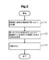
- FIG. 2 is a flowchart of a method for manufacturing a slide bearing pin for a slide bearing according to an embodiment
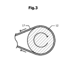
- FIG. 3 is a cross-sectional view of the sliding bearing pin during polishing.
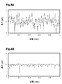
- FIG. 4A is a graph showing an example of the roughness curve of the sliding surface after the first blasting process (step S2)
- FIG. 4B shows the sliding surface after the leveling process of the convex part (step S3). It is a graph which shows an example of a roughness curve.
- FIG. 1A is a cross-sectional view of a rotation mechanism including a slide bearing pin and a bush according to an embodiment
- FIG. 1B is a cross-sectional view taken along one-dot chain line 1B-1B in FIG. 1
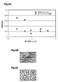
- FIG. 5A is a graph showing the results of evaluating the relationship between the sliding speed and the coefficient of friction using a journal bearing type sliding test device
- FIGS. 5B and 5C show the sliding after step S1 (FIG. 2), respectively. It is the figure which sketched the shading pattern obtained by measuring the surface and the sliding surface after step S3 (FIG. 2) with a surface roughness measuring instrument.
- FIG. 6 is a flowchart of a method for manufacturing a slide bearing pin for a slide bearing according to another embodiment.
- FIG. 7 is a graph showing the results of evaluating the relationship between the sliding speed and the coefficient of friction using a journal bearing type sliding test apparatus.
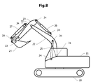
- FIG. 8 is a schematic side view of an excavator to which the slide bearing pin according to the embodiment is applied.
- FIG. 9 is a schematic view of a mold clamping device of a molding machine according to another embodiment.
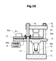
- FIG. 10 is a schematic sectional view of an injection molding machine according to still another embodiment.
- FIG. 11 is a schematic view of a forging press according to still another embodiment.
- FIG. 1A shows a sectional view of a rotating mechanism including a sliding bearing pin (sliding member) and a bush according to the embodiment.
- FIG. 1B is a cross-sectional view taken along one-dot chain line 1B-1B in FIG. 1A.
- a cross-sectional view taken along one-dot chain line 1A-1A in FIG. 1B corresponds to FIG. 1A.
- the cross-sectional view shown in FIG. 1A includes the center of rotation, and the cross-sectional view shown in FIG. 1B is perpendicular to the center of rotation.
- a sliding bearing pin 12 is inserted into the bush 11 and is supported rotatably with respect to the bush 11.
- the sliding bearing pin 12 includes a sliding surface (side surface) that slides with respect to the inner surface of the bush 11.
- the bush 11 is fixed to the first member 10.
- FIG. 1A shows an example in which two bushes 11 having the same shape are attached to the first member 10, the number of the bushes 11 may be one or three or more.
- the slide bearing pin 12 is supported by the second member 13 at both ends thereof. Further, the sliding bearing pin 12 is fixed to the second member 13 so as not to rotate at one end portion 14 thereof.
- the first member 10 rotates with respect to the second member 13 with the central axis of the sliding bearing pin 12 as the rotation axis.
- the first member 10, the second member 13, the bush 11, and the slide bearing pin 12 constitute a rotation mechanism.
- FIG. 2 shows a flowchart of a processing method of the sliding surface of the slide bearing pin 12 according to the embodiment.
- step S1 a cylindrical slide bearing pin 12 having a linear grinding mark remaining on the sliding surface is prepared.
- step S2 the sliding surface of the sliding bearing pin 12 is subjected to a first blasting process to form irregularities that are two-dimensionally irregularly distributed on the sliding surface.
- the particles used in the first blast treatment are polygonal or spherical hard particles having a particle size of 0.1 mm or more and 1 mm or less.
- the first blasting process is performed under a condition where the coverage is 100% or more.
- step S3 the convex portions formed in step S2 are leveled.
- a method for leveling the convex portions there are polishing, burnishing and the like.
- FIG. 3 shows a cross-sectional view of the slide bearing pin 12 during polishing.
- the abrasive cloth 17 contains abrasive particles.
- a polishing cloth 17 is wound around and contacted with an area of 50% or more of the side surface of the sliding bearing pin 12 in the circumferential direction, and the polishing cloth 17 is applied to the polishing cloth 17 by applying tension in the direction of the arrow. Press against pin 12. In this state, the sliding surface is polished by rotating the sliding bearing pin 12.
- the contact area between the sliding surface of the sliding bearing pin 12 and the polishing pad 17 is larger than buffing, polishing can be performed efficiently and uniformly.
- the sliding surface of the sliding bearing pin 12 may be polished using general buffing, or the sliding surface may be polished using other polishing methods.
- FIG. 4A shows an example of the roughness curve of the sliding surface after the first blasting process (step S2).
- the probability density of height when centered on the average line of height is almost symmetrical. In other words, the skewness Rsk obtained from the roughness curve is almost zero.
- FIG. 4B shows an example of the roughness curve of the sliding surface after the convexity leveling process (step S3).
- the convex portion is leveled and flattened, the concave portion substantially retains the shape after the first blast treatment.
- the skewness Rsk obtained from the roughness curve is negative.
- the skewness Rsk is preferably set to ⁇ 1 or less.
- FIG. 5A shows the result of evaluating the relationship between the sliding speed and the coefficient of friction using a journal bearing type sliding test device.
- the horizontal axis represents the sliding speed in the unit “cm / s”, and the vertical axis represents the friction coefficient.
- the surface pressure was about 100 MPa.
- the square symbol in FIG. 5A indicates the friction coefficient of the sliding surface where the linear grinding marks remain, and the circle symbol indicates the first blasting process (step S2) and the convexity leveling process (step S3). The friction coefficient of the sliding surface performed is shown.
- FIG. 5B and FIG. 5C show sketches of shading patterns obtained by measuring the sliding surface after step S1 and the sliding surface after step S3 with a surface roughness measuring instrument, respectively.
- FIG. 5B it can be seen that linear grinding marks remain before the first blasting process (step S2).
- the recesses are irregularly distributed two-dimensionally.
- the friction coefficient is relatively small in the high speed region with the sliding speed of about 0.7 cm / s as a boundary, and the friction surface in the low speed region.
- the coefficient is relatively large. That is, a mixed lubrication region between the fluid lubrication region and the boundary lubrication region exists in the vicinity of the sliding speed of 0.7 cm / s.
- the friction coefficient is significantly reduced, particularly in the range where the sliding speed is 0.7 cm / s or less.
- the decrease in the coefficient of friction is due to the fact that the convex portions are leveled, so that an oil film interposed between the sliding surfaces makes it difficult for the sliding surfaces to directly contact each other.
- the mixed lubrication region between the fluid lubrication region and the boundary lubrication region has shifted to the low speed side (left side of the graph). Since the fluid lubrication region is expanded, not only the friction characteristics but also the wear characteristics are improved.
- the recesses that are irregularly distributed two-dimensionally on the sliding surface form an oil reservoir. Thereby, the image sticking by oil shortage can be suppressed.
- the convex portion height Rpk obtained from the roughness curve of the sliding surface after step S3 is set to 0.03 ⁇ m or less, and the concave portion
- the depth Rvk is preferably 0.1 ⁇ m or more.
- step S3 convex portions that are two-dimensionally irregularly distributed may be removed. For this reason, polishing time can be shortened compared with the method of mirror-finishing the sliding surface where the linear grinding trace remained. Furthermore, since the recesses that are irregularly distributed two-dimensionally are formed in the first blasting process (step S2), it is not necessary to newly form a recess that becomes an oil reservoir after step S3.
- step S2 compressive residual stress can be applied to the sliding bearing pin 12 in the first blasting process. For this reason, the fatigue strength of the slide bearing pin 12 can be increased.
- the particle size of the particles used in the first blast treatment (step S2) is 0.2 mm or more.
- FIG. 6 shows a flowchart of a method for processing a sliding surface of a sliding bearing pin according to another embodiment.
- the processing from step S1 to step S3 is the same as the processing from step S1 to step S3 in the flowchart shown in FIG.
- step S4 the second blast process is performed using particles smaller than the particles used in the first blast process (step S2).
- step S2 finer irregularities are formed on the upper surface of the convex part leveled in step S3.
- the convex portion height Rpk obtained from the roughness curve of the sliding surface after step S3 is preferably 0.03 ⁇ m or less.
- step S4 the convex part height Rpk obtained from the roughness curve of the sliding surface is made larger than the convex part height Rpk before the second blasting process, and It is preferable to make it 0.08 ⁇ m or less.
- FIG. 7 shows the results of evaluating the relationship between the sliding speed and the coefficient of friction using a journal bearing type sliding test apparatus.
- the horizontal axis represents the sliding speed in the unit “cm / s”, and the vertical axis represents the friction coefficient.
- the surface pressure was about 100 MPa.
- the square symbol indicates the friction coefficient of the sliding surface on which linear grinding marks remain, and the circle symbol indicates the sliding surface that has undergone the first blasting process and the convexity leveling process. Indicates the friction coefficient of the moving surface.
- the triangle symbol indicates the friction coefficient of the sliding surface that has been subjected to the second blasting process under the condition that the coverage is 100% or more with respect to a mirror surface having an arithmetic average roughness Ra of 0.01 ⁇ m.
- FIG. 8 shows a schematic side view of an excavator to which the slide bearing pin according to the above embodiment is applied.
- An upper turning body 21 is mounted on the lower traveling body 20 so as to be turnable.
- a boom 22, an arm 23, and a bucket 24 are connected to the upper swing body 21.
- Hydraulic cylinders 25, 26, and 27 drive the boom 22, the arm 23, and the bucket 24, respectively.
- the hydraulic cylinder 27 and the bucket 24 are connected via a link mechanism 28.
- the sliding bearing pin 12 according to the above embodiment is used for the joint portion 34 and the joint portion of the link mechanism 28.
- a plain bearing used for a joint portion of a shovel has a feature that a surface pressure is as high as about 70 MPa and a sliding speed is low.
- the sliding bearing pin 12 according to the above-described embodiment the Stribeck showing the lubrication state between the inner surface of the bush 11 (FIG. 1A) and the sliding surface (side surface) of the sliding bearing pin 12 (FIG. 1A). The curve shifts to the low speed side.
- FIG. 9 shows a schematic view of a mold clamping device of a molding machine according to another embodiment.
- the stationary platen 40 and the toggle support 41 are fixed to the frame at a distance from each other.
- a plurality of tie bars 42 are installed between the fixed platen 40 and the toggle support 41.
- the movable platen 43 is guided by the tie bar 42 and supported so as to be able to advance and retreat with respect to the fixed platen 40.
- the mold mounting surface of the fixed platen 40 and the mold mounting surface of the movable platen 43 are opposed to each other.
- a fixed mold 45 is mounted on the mold mounting surface of the fixed platen 40, and a movable mold 46 is mounted on the mold mounting surface of the movable platen 43.
- a toggle mechanism 50 is disposed between the movable platen 43 and the toggle support 41.
- a driving device 47 is attached to the back surface of the toggle support 41 (the surface facing the side opposite to the movable platen 43).
- a connecting rod 51 extends from the driving device 47 through the toggle support 41 toward the movable platen 43. The drive device 47 moves the connecting rod 51 in the axial direction.
- a crosshead 52 is attached to the tip of the connecting rod 51.
- One end of each of the pair of small toggle levers 53 is attached to the cross head 52 via a slide bearing pin 61.
- One end of the pair of large toggle levers 54 is attached to the toggle support 41 via a slide bearing pin 62.
- the other end of the small toggle lever 53 is attached to an intermediate position of the large toggle lever 54 via a slide bearing pin 63.
- the other end of the large toggle lever 54 is attached to one end of the toggle arm 55 via a slide bearing pin 64.
- the other end of the toggle arm 55 is attached to the movable platen 43 via a sliding bearing pin 65.
- the toggle mechanism 50 can be operated by the driving device 47 moving the connecting rod 51 in the axial direction.
- the processing method of the sliding surface shown in FIG. 2 or 6 can be applied to the processing of the sliding surface (side surface) of the slide bearing pins 61, 62, 63, 64, 65.
- the sliding surface was cylindrical.
- the sliding surface processing method shown in FIGS. 2 and 6 can also be applied to a planar sliding surface.
- the sliding mechanism of the embodiment described below has a flat sliding surface.
- FIG. 10 shows a schematic diagram of an injection molding machine according to another embodiment.
- a toggle mechanism 72 is disposed between the fixed platen 70 and the toggle support 71.
- the toggle support 71 moves up and down with respect to the fixed platen 70 by the toggle mechanism 72.
- Three tie bars 73 extending upward from the toggle support 71 extend through the fixed platen 70 and further upward.
- FIG. 10 shows two tie bars 73.
- a movable platen 75 is fixed to the upper end of the tie bar 73 using a fixing nut 76. When the toggle mechanism 72 is operated to move the toggle support 71 downward, the movable platen 75 approaches the fixed platen 70.
- the two sliding plates 80a and 80b are fixed on the fixed platen 70.
- a rotary table 77 is rotatably supported with respect to one tie bar 73 via a rotary bearing 78, and is supported from below by sliding plates 80a and 80b.
- the two sliding plates 80 a and 80 b are arranged at point-symmetrical positions with respect to the rotation center of the rotary table 77.
- a rotation drive mechanism 79 rotates the rotary table 77.
- FIG. 10 shows a state in which the lower mold 82a is positioned directly above the sliding plate 80a.
- the upper mold 83 is attached to the surface facing the lower side of the movable platen 75.
- the upper mold 83 is disposed immediately above one sliding plate 80a.
- one of the lower molds 82a and 82b can be arranged under the upper mold 83 to produce a molded product, and the produced molded product can be taken out from the other.
- the interval between the fixed platen 70 and the movable platen 75 is narrowed, and a downward load is applied to a part of the rotary table 77, specifically, a position directly above the sliding plate 80a.
- the sliding plate 80 a supports a load applied to the rotary table 77.
- the upper surfaces of the sliding plates 80a and 80b and the lower surface of the rotary table 77 constitute a pair of sliding surfaces.
- the lower surface (sliding surface) of the rotary table 77 and the upper surfaces (sliding surfaces) of the sliding plates 80a and 80b slide.
- the processing method of the sliding surface shown in FIG. 2 or 6 can be applied to the processing of the upper surfaces of the sliding plates 80a and 80b.
- FIG. 11 shows a schematic view of a forging press according to still another embodiment.
- a column 92 extends upward from the four corners of the bed 90, and a crown 91 is fixed to the upper end of the column 92.
- An eccentric shaft 95 spanned in the horizontal direction is rotatably supported on the crown 91.
- a drive source 96 rotates the eccentric shaft 95.
- a slide 98 is connected below the eccentric shaft 95 via a connecting rod 97.
- the slide gibs 100 are attached to the columns 92, respectively.
- the slide give 100 includes a guide surface extending in the vertical direction.
- the slide 98 is guided in the vertical direction with the guided surface facing the guide surface of the slide give 100. By rotating the eccentric shaft 95, the slide 98 can be reciprocated in the vertical direction.
- the lower die holder 105 is attached on the bed 90.
- the lower die 106 is held by the lower die holder 105.
- An upper die holder 107 is attached to the lower surface of the slide 98.
- the upper die 108 is held by the upper die holder 107.
- a copper alloy liner material can be used for the guide surface of the slide give 100.
- the processing method of the sliding surface shown in FIG. 2 or 6 can be applied to processing of the guided surface of the slide 98.
- a liner material made of, for example, copper alloy is used for the guided surface of the slide 98, and the sliding surface processing method shown in FIG. 2 or 6 is applied to the processing of the guiding surface of the slide give 100. Also good.
Landscapes
- Engineering & Computer Science (AREA)
- General Engineering & Computer Science (AREA)
- Mechanical Engineering (AREA)
- Chemical & Material Sciences (AREA)
- Oil, Petroleum & Natural Gas (AREA)
- Sliding-Contact Bearings (AREA)
- Shafts, Cranks, Connecting Bars, And Related Bearings (AREA)
Abstract
Description
第1の摺動面を有する第1の部材と、
前記第1の摺動面に対向する第2の摺動面を含み、前記第1の摺動面と前記第2の摺動面とが摺動する第2の部材と
を有し、
前記第2の摺動面は、二次元的に不規則に分布する凹部を有し、前記第2の摺動面の粗さ曲線から求められるスキューネスが負である摺動機構が提供される。
摺動面に線状の研削痕が残っている摺動部材の前記摺動面に第1のブラスト処理を施すことにより、二次元的に不規則に分布する凹凸を形成する工程と、
凹凸が形成された前記摺動面の凸部を均すことにより、前記摺動面の粗さ曲線から求められるスキューネスを負にする工程と
を有する摺動部材の製造方法が提供される。
図9に、他の実施例による成形機の型締装置の概略図を示す。固定プラテン40及びトグルサポート41が、相互に距離をおいてフレームに固定されている。固定プラテン40とトグルサポート41との間に複数のタイバー42が架設されている。
11 ブッシュ
12 ピン
13 第2の部材
14 一方の端部
17 研磨布
20 下部走行体
21 上部旋回体
22 ブーム
23 アーム
24 バケット
25、26、27 油圧シリンダ
28 リンク機構
31、32、33、34 関節部
40 固定プラテン
41 トグルサポート
42 タイバー
43 可動プラテン
45 固定金型
46 可動金型
47 駆動装置
50 トグル機構
51 連結ロッド
52 クロスヘッド
53 小トグルレバー
54 大トグルレバー
55 トグルアーム
61、62、63、64、65 滑り軸受用ピン
70 固定プラテン
71 トグルサポート
72 トグル機構
73 タイバー
75 可動プラテン
76 固定用ナット
77 ロータリテーブル
78 回転軸受
79 回転駆動装置
80a、80b 滑りプレート
82a、82b 下側金型
83 上側金型
90 ベッド
91 クラウン
92 コラム
95 偏心軸
96 駆動源
97 コンロッド
98 スライド
100 スライドギブ
105 下側ダイホルダ
106 下側金型
107 上側ダイホルダ
108 上側金型
Claims (12)
- 対向する面に対して摺動する摺動面を含む摺動部材であって、前記摺動面は、二次元的に不規則に分布する凹部を有し、前記摺動面の粗さ曲線から求められるスキューネスが負である摺動部材。
- 前記摺動面の粗さ曲線から求められるスキューネスが-1以下である請求項1に記載の摺動部材。
- 前記摺動面の粗さ曲線から求まる凸部高さRpkが0.08μm以下であり、凹部深さRvkが0.1μm以上である請求項1または2に記載の摺動部材。
- 摺動面を有する第1の部材と、
前記第1の部材の摺動面に対向する摺動面を含み、前記第1の部材に対して相対的に摺動する第2の部材と
を有し、
前記第2の部材の摺動面は、二次元的に不規則に分布する凹部を有し、前記第2の部材の摺動面の粗さ曲線から求められるスキューネスが負である摺動機構。 - 前記第2の部材の摺動面の粗さ曲線から求められるスキューネスが-1以下である請求項4に記載の摺動機構。
- 前記第1の部材がブッシュであり、
前記第2の部材が、前記ブッシュに挿入されて回転する滑り軸受用ピンである請求項4または5に記載の摺動機構。 - 前記第1の部材が、垂直な回転軸に対して回転可能に支持され、下方を向く摺動面を持つロータリテーブルであり、
前記第2の部材が、前記ロータリテーブルの下に配置され、前記ロータリテーブルの摺動面に対向する摺動面を持つ滑りプレートであり、
前記ロータリテーブルが回転することにより、前記滑りプレートの摺動面に対して前記ロータリテーブルの摺動面が摺動し、
前記滑りプレートは、前記ロータリテーブルに加わる荷重を支える請求項4または5に記載の摺動機構。 - 前記第1の部材及び前記第2の部材の一方が、鉛直方向に延びる案内面を含むスライドギブであり、
前記第1の部材及び前記第2の部材の他方が、前記スライドギブの前記案内面に被案内面を対向させて上下方向に移動するスライドであり、
前記スライドが上下に移動することにより、前記スライドの前記被案内面が、前記スライドギブの前記案内面に対して摺動する請求項4または5に記載の摺動機構。 - 摺動面に線状の研削痕が残っている摺動部材の前記摺動面に第1のブラスト処理を施すことにより、二次元的に不規則に分布する凹凸を形成する工程と、
凹凸が形成された前記摺動面の凸部を均すことにより、前記摺動面の粗さ曲線から求められるスキューネスを負にする工程と
を有する摺動部材の製造方法。 - 前記第1のブラスト処理において、粒径0.1mm以上の粒子を用いて、前記摺動部材に圧縮残留応力を付与する請求項9に記載の摺動部材の製造方法。
- 前記第1のブラスト処理の後、さらに、前記第1のブラスト処理で用いられた粒子よりも粒径の小さな粒子を用いて、前記摺動面に第2のブラスト処理を施す工程を有する請求項9または10に記載の摺動部材の製造方法。
- 前記凸部を均した後の前記摺動面の粗さ曲線から求まる凸部高さRpkが0.03μm以下であり、凹部深さRvkが0.1μm以上であり、
前記第2のブラスト処理の後の前記摺動面の粗さ曲線から求まる凸部高さRpkが0.08μm以下である請求項11に記載の摺動部材の製造方法。
Priority Applications (3)
| Application Number | Priority Date | Filing Date | Title |
|---|---|---|---|
| JP2017505327A JPWO2016143741A1 (ja) | 2015-03-10 | 2016-03-07 | 摺動部材、摺動機構、及び摺動部材の製造方法 |
| DE112016001146.6T DE112016001146T5 (de) | 2015-03-10 | 2016-03-07 | Gleitelement, Gleitmechanismus und Verfahren zum Herstellen eines Gleitelements |
| CN201680006951.7A CN107208697A (zh) | 2015-03-10 | 2016-03-07 | 滑动部件、滑动机构及滑动部件的制造方法 |
Applications Claiming Priority (2)
| Application Number | Priority Date | Filing Date | Title |
|---|---|---|---|
| JP2015-046587 | 2015-03-10 | ||
| JP2015046587 | 2015-03-10 |
Publications (1)
| Publication Number | Publication Date |
|---|---|
| WO2016143741A1 true WO2016143741A1 (ja) | 2016-09-15 |
Family
ID=56880144
Family Applications (1)
| Application Number | Title | Priority Date | Filing Date |
|---|---|---|---|
| PCT/JP2016/056996 Ceased WO2016143741A1 (ja) | 2015-03-10 | 2016-03-07 | 摺動部材、摺動機構、及び摺動部材の製造方法 |
Country Status (4)
| Country | Link |
|---|---|
| JP (1) | JPWO2016143741A1 (ja) |
| CN (1) | CN107208697A (ja) |
| DE (1) | DE112016001146T5 (ja) |
| WO (1) | WO2016143741A1 (ja) |
Cited By (1)
| Publication number | Priority date | Publication date | Assignee | Title |
|---|---|---|---|---|
| JP7855809B1 (ja) | 2025-01-21 | 2026-05-08 | バンドー化学株式会社 | ワイパーブレードラバー及びその製造方法並びにその検査方法 |
Families Citing this family (3)
| Publication number | Priority date | Publication date | Assignee | Title |
|---|---|---|---|---|
| PL3538795T3 (pl) † | 2016-11-10 | 2023-03-13 | Hutchinson | Zestaw uszczelniający, łożysko toczne zawierające taki zestaw, i sposób wytwarzania takiego zestawu |
| JP6885491B2 (ja) * | 2019-04-26 | 2021-06-16 | 日本精工株式会社 | 摺動部材の摩擦設計方法および表面粗さ管理方法並びに摺動機構の製造方法 |
| JP7487146B2 (ja) * | 2021-06-11 | 2024-05-20 | 株式会社神戸製鋼所 | 摺動部材、摺動部材の製造方法及び摺動部材の評価方法 |
Citations (7)
| Publication number | Priority date | Publication date | Assignee | Title |
|---|---|---|---|---|
| JP2724219B2 (ja) * | 1989-09-28 | 1998-03-09 | エヌティエヌ株式会社 | 転がり軸受 |
| JP2007271013A (ja) * | 2006-03-31 | 2007-10-18 | Nidec Sankyo Corp | 動圧溝、および動圧溝の形成方法 |
| JP2007284706A (ja) * | 2006-04-12 | 2007-11-01 | Toyota Industries Corp | 摺動材料 |
| JP2012189223A (ja) * | 2012-06-18 | 2012-10-04 | Nissan Motor Co Ltd | 低摩擦摺動部材 |
| JP2013096429A (ja) * | 2011-10-28 | 2013-05-20 | Taiho Kogyo Co Ltd | すべり軸受およびその製造方法 |
| JP2014152373A (ja) * | 2013-02-12 | 2014-08-25 | Kayaba Ind Co Ltd | 摺動部材 |
| JP5765490B2 (ja) * | 2012-10-25 | 2015-08-19 | 千住金属工業株式会社 | 摺動部材及び摺動部材の製造方法 |
Family Cites Families (7)
| Publication number | Priority date | Publication date | Assignee | Title |
|---|---|---|---|---|
| JPS6012671Y2 (ja) * | 1979-05-25 | 1985-04-24 | 日本電信電話株式会社 | 上下微動回転テ−ブル |
| JPS62146600U (ja) * | 1986-03-11 | 1987-09-16 | ||
| GB2219359B (en) * | 1988-05-30 | 1992-11-04 | Ntn Toyo Bearing Co Ltd | Roller elements for machine parts such as roller bearings. |
| JPH102335A (ja) * | 1996-06-19 | 1998-01-06 | Ntn Corp | 軸受装置 |
| JP4301623B2 (ja) * | 1999-03-26 | 2009-07-22 | 株式会社東芝 | 耐摩耗部材 |
| JP2004116707A (ja) * | 2002-09-27 | 2004-04-15 | Nippon Piston Ring Co Ltd | 組合せ摺動部材 |
| RU2540047C1 (ru) * | 2013-07-19 | 2015-01-27 | Федеральное государственное бюджетное образовательное учреждение высшего профессионального образования "Алтайский государственный технический университет им. И.И. Ползунова" (АлтГТУ) | Сферический двухрядный подшипник качения |
-
2016
- 2016-03-07 JP JP2017505327A patent/JPWO2016143741A1/ja active Pending
- 2016-03-07 WO PCT/JP2016/056996 patent/WO2016143741A1/ja not_active Ceased
- 2016-03-07 DE DE112016001146.6T patent/DE112016001146T5/de not_active Ceased
- 2016-03-07 CN CN201680006951.7A patent/CN107208697A/zh active Pending
Patent Citations (7)
| Publication number | Priority date | Publication date | Assignee | Title |
|---|---|---|---|---|
| JP2724219B2 (ja) * | 1989-09-28 | 1998-03-09 | エヌティエヌ株式会社 | 転がり軸受 |
| JP2007271013A (ja) * | 2006-03-31 | 2007-10-18 | Nidec Sankyo Corp | 動圧溝、および動圧溝の形成方法 |
| JP2007284706A (ja) * | 2006-04-12 | 2007-11-01 | Toyota Industries Corp | 摺動材料 |
| JP2013096429A (ja) * | 2011-10-28 | 2013-05-20 | Taiho Kogyo Co Ltd | すべり軸受およびその製造方法 |
| JP2012189223A (ja) * | 2012-06-18 | 2012-10-04 | Nissan Motor Co Ltd | 低摩擦摺動部材 |
| JP5765490B2 (ja) * | 2012-10-25 | 2015-08-19 | 千住金属工業株式会社 | 摺動部材及び摺動部材の製造方法 |
| JP2014152373A (ja) * | 2013-02-12 | 2014-08-25 | Kayaba Ind Co Ltd | 摺動部材 |
Cited By (1)
| Publication number | Priority date | Publication date | Assignee | Title |
|---|---|---|---|---|
| JP7855809B1 (ja) | 2025-01-21 | 2026-05-08 | バンドー化学株式会社 | ワイパーブレードラバー及びその製造方法並びにその検査方法 |
Also Published As
| Publication number | Publication date |
|---|---|
| CN107208697A (zh) | 2017-09-26 |
| JPWO2016143741A1 (ja) | 2017-12-21 |
| DE112016001146T5 (de) | 2017-12-21 |
Similar Documents
| Publication | Publication Date | Title |
|---|---|---|
| JP6824563B2 (ja) | 摺動機構 | |
| JPS62173161A (ja) | 加工物表面のミクロ仕上げ装置及び方法 | |
| KR20100102617A (ko) | 저 마찰 요소의 제조 | |
| WO2016143741A1 (ja) | 摺動部材、摺動機構、及び摺動部材の製造方法 | |
| CN107931605B (zh) | 用于摩擦副表面微织构的3d打印制作方法 | |
| JP2010535107A (ja) | クランクシャフトを強化するための方法及び装置 | |
| KR20160046805A (ko) | 슬라이딩 표면, 상기 슬라이딩 표면을 제조하기 위한 공구 및 방법 | |
| CN113231954A (zh) | 一种四点接触球轴承套圈的超精加工装置和加工方法 | |
| CN107073673A (zh) | 用于抛光加工旋转对称的工件区段的周缘面的方法和装置 | |
| CN107584182A (zh) | 一种微织构自润滑导轨的制备方法 | |
| JP4817039B2 (ja) | 摺動装置 | |
| JP2019167995A (ja) | 転動部品、軸受およびそれらの製造方法 | |
| RU2398668C2 (ru) | Способ ремонта гидрораспределителей | |
| KR20140066235A (ko) | 크랭크샤프트의 표면 품질을 향상시키는 방법 | |
| JPS59115157A (ja) | 環状被加工物の内周面加工用超仕上加工装置 | |
| JP2007002989A (ja) | 摺動部材、当該摺動部材を適用したシリンダ、および当該シリンダを適用した内燃機関 | |
| JP6549851B2 (ja) | 摺動部材のテクスチャ加工方法 | |
| CN118682659A (zh) | 一种研磨工具及手工内孔研磨方法 | |
| JP5344299B2 (ja) | 極低速回転用の軸受装置 | |
| CN206677496U (zh) | 一种气缸套内孔滚花装置 | |
| CN102548708B (zh) | 具有磨石的磨具和使用所述磨具进行磨削的方法 | |
| CN102489933A (zh) | 盾构密封接触面修复方法 | |
| CN105538126A (zh) | 一种超精机摆头机构 | |
| WO2006104130A1 (ja) | 超仕上砥石及びそれを用いた超仕上加工方法 | |
| CN205325419U (zh) | 超精机摆头机构 |
Legal Events
| Date | Code | Title | Description |
|---|---|---|---|
| 121 | Ep: the epo has been informed by wipo that ep was designated in this application |
Ref document number: 16761709 Country of ref document: EP Kind code of ref document: A1 |
|
| ENP | Entry into the national phase |
Ref document number: 2017505327 Country of ref document: JP Kind code of ref document: A |
|
| WWE | Wipo information: entry into national phase |
Ref document number: 112016001146 Country of ref document: DE |
|
| 122 | Ep: pct application non-entry in european phase |
Ref document number: 16761709 Country of ref document: EP Kind code of ref document: A1 |