WO2016143505A1 - 自動車用配電装置 - Google Patents
自動車用配電装置 Download PDFInfo
- Publication number
- WO2016143505A1 WO2016143505A1 PCT/JP2016/055233 JP2016055233W WO2016143505A1 WO 2016143505 A1 WO2016143505 A1 WO 2016143505A1 JP 2016055233 W JP2016055233 W JP 2016055233W WO 2016143505 A1 WO2016143505 A1 WO 2016143505A1
- Authority
- WO
- WIPO (PCT)
- Prior art keywords
- wireless
- wireless device
- power
- engine room
- disposed
- Prior art date
- Legal status (The legal status is an assumption and is not a legal conclusion. Google has not performed a legal analysis and makes no representation as to the accuracy of the status listed.)
- Ceased
Links
Images

Classifications
-
- H—ELECTRICITY
- H02—GENERATION; CONVERSION OR DISTRIBUTION OF ELECTRIC POWER
- H02J—CIRCUIT ARRANGEMENTS OR SYSTEMS FOR SUPPLYING OR DISTRIBUTING ELECTRIC POWER; SYSTEMS FOR STORING ELECTRIC ENERGY
- H02J50/00—Circuit arrangements or systems for wireless supply or distribution of electric power
- H02J50/05—Circuit arrangements or systems for wireless supply or distribution of electric power using capacitive coupling
-
- B—PERFORMING OPERATIONS; TRANSPORTING
- B60—VEHICLES IN GENERAL
- B60R—VEHICLES, VEHICLE FITTINGS, OR VEHICLE PARTS, NOT OTHERWISE PROVIDED FOR
- B60R16/00—Electric or fluid circuits specially adapted for vehicles and not otherwise provided for; Arrangement of elements of electric or fluid circuits specially adapted for vehicles and not otherwise provided for
- B60R16/02—Electric or fluid circuits specially adapted for vehicles and not otherwise provided for; Arrangement of elements of electric or fluid circuits specially adapted for vehicles and not otherwise provided for electric constitutive elements
- B60R16/03—Electric or fluid circuits specially adapted for vehicles and not otherwise provided for; Arrangement of elements of electric or fluid circuits specially adapted for vehicles and not otherwise provided for electric constitutive elements for supply of electrical power to vehicle subsystems or for
-
- H—ELECTRICITY
- H02—GENERATION; CONVERSION OR DISTRIBUTION OF ELECTRIC POWER
- H02J—CIRCUIT ARRANGEMENTS OR SYSTEMS FOR SUPPLYING OR DISTRIBUTING ELECTRIC POWER; SYSTEMS FOR STORING ELECTRIC ENERGY
- H02J50/00—Circuit arrangements or systems for wireless supply or distribution of electric power
- H02J50/10—Circuit arrangements or systems for wireless supply or distribution of electric power using inductive coupling
-
- H—ELECTRICITY
- H02—GENERATION; CONVERSION OR DISTRIBUTION OF ELECTRIC POWER
- H02J—CIRCUIT ARRANGEMENTS OR SYSTEMS FOR SUPPLYING OR DISTRIBUTING ELECTRIC POWER; SYSTEMS FOR STORING ELECTRIC ENERGY
- H02J2310/00—The network for supplying or distributing electric power characterised by its spatial reach or by the load
- H02J2310/40—The network being an on-board power network, i.e. within a vehicle
- H02J2310/46—The network being an on-board power network, i.e. within a vehicle for ICE-powered road vehicles
-
- H—ELECTRICITY
- H04—ELECTRIC COMMUNICATION TECHNIQUE
- H04B—TRANSMISSION
- H04B7/00—Radio transmission systems, i.e. using radiation field
- H04B7/24—Radio transmission systems, i.e. using radiation field for communication between two or more posts
- H04B7/26—Radio transmission systems, i.e. using radiation field for communication between two or more posts at least one of which is mobile
Definitions
- the present invention relates to a power distribution device that enables an electrical connection between a space separated by a partition wall in an automobile, for example, a vehicle compartment and an engine room.
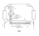
- FIG. 1 An example of a conventional automobile power distribution device is shown in FIG.
- the battery 2 is connected to the relay box 3.
- the relay box 3 is connected to an electrical connection box 6 disposed in the passenger compartment 5 via a wire harness 4 in which a large number of power supply lines are collected.
- a large number of electrical devices are connected to the electrical junction box 6. Each electric device is supplied with required power from the battery 2 via the relay box 3, the wire harness 4, and the electric connection box 6.
- An ECU 7 is disposed in the engine room 1 and controls the operation of electrical equipment disposed in the engine room 1.
- the ECU 7 is connected to an ECU 8 disposed in the passenger compartment 5 via a wire harness 9, and the electrical equipment in the engine room 1 is linked with the electrical equipment in the passenger compartment 5 based on communication with the ECU 8. Control to work.
- the ECU 8 disposed in the passenger compartment 5 controls the electrical equipment in the passenger compartment 5 to cooperate with the electrical equipment in the engine compartment 1 based on communication with the ECU 7.
- the wire harnesses 4 and 9 are inserted through through holes formed in the partition wall 10 between the engine room 1 and the vehicle compartment 5.
- a grommet 10a through which the wire harnesses 4 and 9 are inserted is fitted into the through hole.
- the grommet 10a through which the wire harnesses 4 and 9 are inserted is attached to the through holes of the partition wall 10, so that rainwater in the engine room 1 enters the vehicle compartment 5 through the wire harnesses 4 and 9. Sometimes.
- Patent Document 1 discloses a grommet having a waterproof function.
- the waterproof function may not work reliably.
- the diameter of a wire harness differs for every vehicle model, it is necessary to design and manufacture the grommet according to the diameter for every vehicle model. This increases the part cost.
- an automotive power distribution device includes a first wireless power feeding unit and is a first wireless device disposed in an engine room, the battery being disposed in the engine room.
- the first and second wireless power feeding units are configured to perform wireless power feeding from the first wireless device to the second wireless device, and the first and second wireless devices are configured to transmit the engine. It arrange
- the first wireless device and the second wireless device each include a first wireless communication unit and a second wireless communication unit, and the first and second wireless communication units, respectively. Is preferably configured to wirelessly transmit and receive communication signals between the electrical equipment disposed in the engine room and the electrical equipment in the vehicle compartment.
- the first wireless device and the second wireless device are installed at positions facing each other across the partition, and the first wireless device and the first of the partitions are It is preferable that the portion sandwiched between the two wireless devices is made of a non-metallic portion.
- the first and second wireless power feeding units are arranged at positions facing each other with the partition wall interposed therebetween, and the first and second wireless communication units are opposed to each other with the partition wall interposed therebetween. It is preferable that the partition wall has a through hole at a position between the first and second wireless power feeding units and a position between the first and second wireless communication units. .
- the first wireless device is a first communication control unit that is interposed between the electric device in the engine room and the first wireless communication unit and transmits and receives communication signals.
- the second wireless device includes a second communication control unit that is interposed between the electric device in the vehicle interior and the second wireless communication unit and transmits and receives communication signals.
- the communication between the electric device in the engine room and the first wireless communication unit is managed by the first communication control unit, and the communication between the electric device in the vehicle interior and the second wireless communication unit is the second. Managed by the communication control unit.
- an automobile including an automobile power distribution device includes an engine room, a vehicle compartment, and a body having a partition wall between the engine room and the vehicle compartment, and the automobile power distribution device includes a first wireless power feeding unit and is disposed in the engine room.
- a second wireless device and a power distribution device that supplies electric power supplied to the second wireless device to an electrical device disposed in the vehicle interior, wherein the first and second wireless power feeding units are The first wireless device is configured to perform wireless power feeding from the first wireless device to the second wireless device, and the first and second wireless devices are adjacent to or in contact with the partition wall. Is located in
- the automobile power distribution device of the present invention it is possible to reliably prevent rainwater from entering the vehicle compartment.
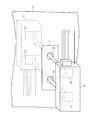
- the battery 12 is connected to a relay box 13 in the engine room 11.
- the output power of the battery 12 is supplied from the relay box 13 to the first wireless device 14. Necessary power is also supplied from the relay box 13 to the electrical equipment in the engine room 11.
- a first ECU 15 is disposed in the engine room 11.
- the first ECU 15 controls the operation of the electrical equipment disposed in the engine room 11 and transmits / receives communication signals to / from the first wireless device 14.
- the first wireless device 14 is disposed adjacent to or in contact with the partition wall 17 that separates the engine room 11 and the vehicle compartment 16.
- a second wireless device 18 is disposed near the partition wall 17 or in contact with the partition wall 17 at a position facing the first wireless device 14 across the partition wall 17. Yes.
- the first wireless device 14 can wirelessly feed the power supplied from the battery 12 to the second wireless device 18 and can transmit and receive various communication signals to and from the second wireless device 18.
- the second wireless device 18 is connected to a second ECU 19 disposed in the passenger compartment 16 and a power distribution device (electrical connection box 20 in the present embodiment).
- the electric power supplied to the second wireless device 18 is supplied to the electric junction box 20, and the electric power is further supplied to a number of electric devices arranged in the passenger compartment 16.
- the second ECU 19 communicates with the first ECU 15 via the first and second wireless devices 14 and 18 to control the electric devices in the engine room 11 and the electric devices in the vehicle compartment 16.
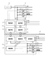
- FIG. 2 shows the configuration of the first and second radio apparatuses 14 and 18.
- the first wireless device 14 is supplied with power from the battery 12 via the relay box 13.
- the first wireless device 14 includes a power supply control unit 21, a communication control unit 22, a wireless power feeding unit 23, and a wireless communication unit 24.
- the second wireless device 18 includes a power control unit 25, a communication control unit 26, a wireless power feeding unit 27, and a wireless communication unit 28.
- the power control unit 21 of the first wireless device 14 controls the opening and closing of the relay 29 in the relay box 13 based on the control signal output from the wireless communication unit 24.
- the relay box 13 supplies electric power supplied from the battery 12 to electric devices in the engine room 11.
- the relay box 13 is provided with an ignition device that requires power when the ignition switch is turned on, an accessory device that is supplied with power other than when the ignition switch is turned on, an illuminator, and a warning sound. Supply power to equipment, engine related equipment, etc.
- the power supply control unit 21 controls the opening / closing of each relay 29 to control the power supply to each device.
- the communication control unit 22 of the first wireless device 14 is connected to the first ECU 15 and communication devices such as a device that performs CAN communication and a device that performs LIN communication, and between these devices and the wireless communication unit 24. Acts as a buffer.
- the wireless communication unit 24 of the first wireless device 14 can bidirectionally communicate with the wireless communication unit 28 of the second wireless device 18 by a wireless communication method such as NFC or Transferjet.
- the wireless power supply unit 23 of the first wireless device 14 can wirelessly supply power to the wireless power supply unit 27 of the second wireless device 18. That is, in the present embodiment, the wireless power supply unit 23 operates as a power transmission unit, and the wireless power supply unit 27 operates as a power reception unit.
- Examples of the wireless power feeding method that can be adopted in the present invention include an electromagnetic induction method and an electric field coupling method.
- the power supplied to the wireless power feeding unit 27 is, via each relay 30, an ignition device that requires power when the ignition switch is turned on, an accessory device that is supplied with power other than when the ignition switch is turned on, and It is supplied to electrical equipment in the passenger compartment 16 such as a door lock device and a seat adjustment device.
- the power control unit 25 of the second wireless device 18 controls the opening and closing of the relay 30 based on the control signal output from the wireless communication unit 28. Therefore, the power supply control unit 25 controls the opening / closing of each relay 30 to control the power supply to each device.
- the communication control unit 26 of the second wireless device 18 is connected to the second ECU 19 and communication devices such as a device that performs CAN communication and a device that performs LIN communication, and between these devices and the wireless communication unit 28. Acts as a buffer.
- the partition wall 17 between the first wireless device 14 and the second wireless device 18 is provided with a non-metal portion 31 such as a synthetic resin plate, and the first wireless device 14 and the first wireless device 14 Wireless power feeding and wireless communication with the second wireless device 18 are not disturbed.
- the non-metal part 31 has a through hole 32 at a position sandwiched between the wireless power feeding parts 23 and 27 and a position sandwiched between the wireless communication parts 24 and 28. You may have. Only the through holes 32 may be provided in the partition wall 17 without providing the non-metal portion 31.
- the power supplied from the battery 12 is supplied to each device in the engine room 11 via the relay box 13 controlled by the power supply control unit 21.
- the power supplied from the battery 12 is also supplied to the first wireless device 14 via the relay box 13, and the power is supplied from the wireless power supply unit 23 of the first wireless device 14 to the wireless power supply unit 27 of the second wireless device. Used for wireless power feeding. Then, power is supplied from the wireless power feeding unit 27 to each device in the passenger compartment 16.
- Communication signals output from the first ECU 15 and other devices in the engine room 11 are transmitted from the communication control unit 22 of the first wireless device 14 to the wireless communication unit 24 and the wireless communication unit 28 of the second wireless device 18. Further, it is transmitted to the communication control unit 26 and transferred from the communication control unit 26 to the second ECU 19 and other devices.
- communication signals output from the second ECU 19 and other devices in the passenger compartment 16 are transmitted from the communication control unit 26 of the second wireless device 18 to the wireless communication unit 28 and the wireless signal of the first wireless device 14.
- the data is transmitted to the communication unit 24 and further to the communication control unit 22, and transferred from the communication control unit 22 to the first ECU 15 and other devices.
- the above-described automobile power distribution device has the following effects. (1) Power can be supplied from the battery 12 in the engine room 11 to the electrical equipment in the vehicle compartment 16 via the wireless power feeding units 23 and 24. (2) It is not necessary to form a through hole for penetrating the wire harness in the partition wall 17 separating the engine room 11 and the vehicle compartment 16. Therefore, it is possible to prevent rainwater from entering the vehicle compartment 16 from the engine room 11. (3) Since there is no need to form a through hole, it is not necessary to prepare a grommet for each vehicle type. There is no need to form through holes with different diameters for each vehicle type. (4) Since the wire harness is not passed through the through hole, it is not necessary to bend the wire harness near the through hole.
- the wiring work of the wire harness extending from the first wireless device 14 and the second wireless device 18 in the vicinity of the partition wall 17 can be easily performed.
- a communication signal between the electric device in the engine room 11 and the electric device in the vehicle compartment 16 can be transmitted via the wireless communication units 24 and 28. Therefore, it is not necessary to penetrate the wire harness for transmitting the communication signal to the partition wall 17.
- the portion of the partition wall 17 between the first wireless device 14 and the second wireless device 18 is composed of the non-metal part 31, the first wireless device 14 and the second wireless device 18 Wireless power feeding and wireless communication can be further stabilized.
- the partition wall 17 has the through hole 32 at a position sandwiched between the wireless power feeding units 23 and 27 and a position sandwiched between the wireless communication units 24 and 28, the wireless power feeding and the wireless communication are more stable. Can be made.
- the above embodiment may be modified as follows.
- the relay 30 may be provided not in the second wireless device 18 but in a relay box or the like outside the second wireless device 18.
Landscapes
- Engineering & Computer Science (AREA)
- Computer Networks & Wireless Communication (AREA)
- Power Engineering (AREA)
- Mechanical Engineering (AREA)
- Charge And Discharge Circuits For Batteries Or The Like (AREA)
- Selective Calling Equipment (AREA)
- Cable Accessories (AREA)
- Near-Field Transmission Systems (AREA)
- Installation Of Indoor Wiring (AREA)
Priority Applications (2)
| Application Number | Priority Date | Filing Date | Title |
|---|---|---|---|
| US15/554,622 US20180019616A1 (en) | 2015-03-06 | 2016-02-23 | Automobile power distribution apparatus |
| CN201680010733.0A CN107406045A (zh) | 2015-03-06 | 2016-02-23 | 汽车用配电装置 |
Applications Claiming Priority (2)
| Application Number | Priority Date | Filing Date | Title |
|---|---|---|---|
| JP2015-044814 | 2015-03-06 | ||
| JP2015044814A JP2016164033A (ja) | 2015-03-06 | 2015-03-06 | 自動車用配電装置 |
Publications (1)
| Publication Number | Publication Date |
|---|---|
| WO2016143505A1 true WO2016143505A1 (ja) | 2016-09-15 |
Family
ID=56875811
Family Applications (1)
| Application Number | Title | Priority Date | Filing Date |
|---|---|---|---|
| PCT/JP2016/055233 Ceased WO2016143505A1 (ja) | 2015-03-06 | 2016-02-23 | 自動車用配電装置 |
Country Status (4)
| Country | Link |
|---|---|
| US (1) | US20180019616A1 (enExample) |
| JP (1) | JP2016164033A (enExample) |
| CN (1) | CN107406045A (enExample) |
| WO (1) | WO2016143505A1 (enExample) |
Families Citing this family (7)
| Publication number | Priority date | Publication date | Assignee | Title |
|---|---|---|---|---|
| JP2018125900A (ja) * | 2017-01-30 | 2018-08-09 | 株式会社東芝 | 電気機器システム |
| JP6738847B2 (ja) * | 2018-03-13 | 2020-08-12 | 矢崎総業株式会社 | 車両用電源供給システム |
| US11027680B2 (en) | 2018-12-13 | 2021-06-08 | Ford Global Technologies, Llc | Vehicle tracks |
| JP7305406B2 (ja) * | 2019-04-04 | 2023-07-10 | キヤノン株式会社 | 撮像システム及び撮像装置 |
| CN110562167A (zh) * | 2019-08-06 | 2019-12-13 | 吉利汽车研究院(宁波)有限公司 | 一种无线控制系统及车辆 |
| JP7334614B2 (ja) * | 2019-12-24 | 2023-08-29 | 株式会社オートネットワーク技術研究所 | 車載中継装置 |
| CN120039208A (zh) * | 2025-03-12 | 2025-05-27 | 广州小鹏汽车科技有限公司 | 配电方法、配电系统及配电设备 |
Citations (3)
| Publication number | Priority date | Publication date | Assignee | Title |
|---|---|---|---|---|
| JPH0983414A (ja) * | 1995-09-14 | 1997-03-28 | Omron Corp | 無線電力伝送装置 |
| JP2009120019A (ja) * | 2007-11-14 | 2009-06-04 | Autonetworks Technologies Ltd | 車載電力供給システム |
| JP2015023638A (ja) * | 2013-07-17 | 2015-02-02 | 株式会社リューテック | 無線電力伝送システム |
Family Cites Families (18)
| Publication number | Priority date | Publication date | Assignee | Title |
|---|---|---|---|---|
| JP2002247781A (ja) * | 2001-02-21 | 2002-08-30 | Yazaki Corp | 給電装置 |
| JP2002252937A (ja) * | 2001-02-26 | 2002-09-06 | Yazaki Corp | 給電装置 |
| JP2003052137A (ja) * | 2001-08-07 | 2003-02-21 | Toyota Motor Corp | 車両用電力伝送装置及び車両用電力伝送モジュール |
| US20090072782A1 (en) * | 2002-12-10 | 2009-03-19 | Mitch Randall | Versatile apparatus and method for electronic devices |
| JP2005081863A (ja) * | 2003-09-04 | 2005-03-31 | Auto Network Gijutsu Kenkyusho:Kk | 無線ハーネスシステム及びワイヤーハーネス装置 |
| JP2005294920A (ja) * | 2004-03-31 | 2005-10-20 | Auto Network Gijutsu Kenkyusho:Kk | 撮像装置および当該撮像装置を用いた撮像システム |
| US7566984B2 (en) * | 2005-09-13 | 2009-07-28 | Nissan Technical Center North America, Inc. | Vehicle cabin power transfer arrangement |
| US7438602B2 (en) * | 2006-07-18 | 2008-10-21 | Deere & Company | Ruggedized USB port |
| DE102007012304A1 (de) * | 2007-03-14 | 2008-09-18 | Robert Bosch Gmbh | Schnittstelle in einem Fahrzeug und Verfahren zum Datenaustausch |
| DE202007009033U1 (de) * | 2007-06-26 | 2007-08-30 | Kiekert Ag | Elektronische Zustandserfassungseinrichtung |
| JP2009120156A (ja) * | 2007-11-19 | 2009-06-04 | Mitsubishi Cable Ind Ltd | 車両用電装システム |
| CN107026511A (zh) * | 2008-09-27 | 2017-08-08 | 韦特里西提公司 | 无线能量转移系统 |
| US9577436B2 (en) * | 2008-09-27 | 2017-02-21 | Witricity Corporation | Wireless energy transfer for implantable devices |
| US9318922B2 (en) * | 2008-09-27 | 2016-04-19 | Witricity Corporation | Mechanically removable wireless power vehicle seat assembly |
| US8620354B2 (en) * | 2009-12-03 | 2013-12-31 | Richard K. Beasley | Method and system for selectively limiting wireless communication in a motor vehicle |
| JP5737856B2 (ja) * | 2010-04-06 | 2015-06-17 | 朝日電装株式会社 | スイッチ装置 |
| US10468914B2 (en) * | 2013-03-11 | 2019-11-05 | Robert Bosch Gmbh | Contactless power transfer system |
| US9906066B2 (en) * | 2015-04-13 | 2018-02-27 | Motorola Solutions, Inc. | Visor-mountable wireless charger and method of wireless charging |
-
2015
- 2015-03-06 JP JP2015044814A patent/JP2016164033A/ja active Pending
-
2016
- 2016-02-23 US US15/554,622 patent/US20180019616A1/en not_active Abandoned
- 2016-02-23 WO PCT/JP2016/055233 patent/WO2016143505A1/ja not_active Ceased
- 2016-02-23 CN CN201680010733.0A patent/CN107406045A/zh active Pending
Patent Citations (3)
| Publication number | Priority date | Publication date | Assignee | Title |
|---|---|---|---|---|
| JPH0983414A (ja) * | 1995-09-14 | 1997-03-28 | Omron Corp | 無線電力伝送装置 |
| JP2009120019A (ja) * | 2007-11-14 | 2009-06-04 | Autonetworks Technologies Ltd | 車載電力供給システム |
| JP2015023638A (ja) * | 2013-07-17 | 2015-02-02 | 株式会社リューテック | 無線電力伝送システム |
Also Published As
| Publication number | Publication date |
|---|---|
| US20180019616A1 (en) | 2018-01-18 |
| JP2016164033A (ja) | 2016-09-08 |
| CN107406045A (zh) | 2017-11-28 |
Similar Documents
| Publication | Publication Date | Title |
|---|---|---|
| WO2016143505A1 (ja) | 自動車用配電装置 | |
| CN108698546A (zh) | 车身线束技术 | |
| JP6445263B2 (ja) | 車両用ハーネス構造 | |
| US20160288741A1 (en) | Wireless Electrical Interface System | |
| JP2016147558A (ja) | 車両用電装機器接続システム | |
| CN110450735B (zh) | 线束、用于线束的元件模块和车辆元件 | |
| JP6326075B2 (ja) | 車両用電装システム | |
| CN110663151B (zh) | 车载系统 | |
| CN110621547A (zh) | 车载电力供给系统及车载控制装置 | |
| US10464509B2 (en) | Electrical equipment module | |
| US20180015889A1 (en) | Automotive power supply device | |
| CN102555939B (zh) | 线束 | |
| JP7398210B2 (ja) | 電気接続箱 | |
| JP2016196274A (ja) | 自動車用配電装置 | |
| JP2016196273A (ja) | 自動車用配電装置 | |
| USRE49381E1 (en) | Wireless electrical interface system | |
| JP2018012389A (ja) | 配索材の固定構造およびインナーパネルモジュール | |
| JP6843421B2 (ja) | 物 | |
| JP2005081863A (ja) | 無線ハーネスシステム及びワイヤーハーネス装置 | |
| JP7562180B2 (ja) | 物 | |
| JP2012054688A (ja) | 車載通信システム、入出力装置及び車載機器制御方法 | |
| JPH11266251A (ja) | 車両内配線装置 | |
| JP3208264U (ja) | 直流電源通信装置を備えた車両用遠隔通信装置 | |
| US20160339853A1 (en) | Wire harness | |
| WO2016093336A1 (ja) | 車載アンテナ |
Legal Events
| Date | Code | Title | Description |
|---|---|---|---|
| 121 | Ep: the epo has been informed by wipo that ep was designated in this application |
Ref document number: 16761477 Country of ref document: EP Kind code of ref document: A1 |
|
| WWE | Wipo information: entry into national phase |
Ref document number: 15554622 Country of ref document: US |
|
| NENP | Non-entry into the national phase |
Ref country code: DE |
|
| 122 | Ep: pct application non-entry in european phase |
Ref document number: 16761477 Country of ref document: EP Kind code of ref document: A1 |