WO2016143505A1 - Electricity distribution device for automobile - Google Patents
Electricity distribution device for automobile Download PDFInfo
- Publication number
- WO2016143505A1 WO2016143505A1 PCT/JP2016/055233 JP2016055233W WO2016143505A1 WO 2016143505 A1 WO2016143505 A1 WO 2016143505A1 JP 2016055233 W JP2016055233 W JP 2016055233W WO 2016143505 A1 WO2016143505 A1 WO 2016143505A1
- Authority
- WO
- WIPO (PCT)
- Prior art keywords
- wireless
- wireless device
- power
- engine room
- disposed
- Prior art date
Links
Images

Classifications
-
- H—ELECTRICITY
- H02—GENERATION; CONVERSION OR DISTRIBUTION OF ELECTRIC POWER
- H02J—CIRCUIT ARRANGEMENTS OR SYSTEMS FOR SUPPLYING OR DISTRIBUTING ELECTRIC POWER; SYSTEMS FOR STORING ELECTRIC ENERGY
- H02J50/00—Circuit arrangements or systems for wireless supply or distribution of electric power
- H02J50/05—Circuit arrangements or systems for wireless supply or distribution of electric power using capacitive coupling
-
- B—PERFORMING OPERATIONS; TRANSPORTING
- B60—VEHICLES IN GENERAL
- B60R—VEHICLES, VEHICLE FITTINGS, OR VEHICLE PARTS, NOT OTHERWISE PROVIDED FOR
- B60R16/00—Electric or fluid circuits specially adapted for vehicles and not otherwise provided for; Arrangement of elements of electric or fluid circuits specially adapted for vehicles and not otherwise provided for
- B60R16/02—Electric or fluid circuits specially adapted for vehicles and not otherwise provided for; Arrangement of elements of electric or fluid circuits specially adapted for vehicles and not otherwise provided for electric constitutive elements
- B60R16/03—Electric or fluid circuits specially adapted for vehicles and not otherwise provided for; Arrangement of elements of electric or fluid circuits specially adapted for vehicles and not otherwise provided for electric constitutive elements for supply of electrical power to vehicle subsystems or for
-
- H—ELECTRICITY
- H02—GENERATION; CONVERSION OR DISTRIBUTION OF ELECTRIC POWER
- H02J—CIRCUIT ARRANGEMENTS OR SYSTEMS FOR SUPPLYING OR DISTRIBUTING ELECTRIC POWER; SYSTEMS FOR STORING ELECTRIC ENERGY
- H02J50/00—Circuit arrangements or systems for wireless supply or distribution of electric power
- H02J50/10—Circuit arrangements or systems for wireless supply or distribution of electric power using inductive coupling
-
- H—ELECTRICITY
- H02—GENERATION; CONVERSION OR DISTRIBUTION OF ELECTRIC POWER
- H02J—CIRCUIT ARRANGEMENTS OR SYSTEMS FOR SUPPLYING OR DISTRIBUTING ELECTRIC POWER; SYSTEMS FOR STORING ELECTRIC ENERGY
- H02J2310/00—The network for supplying or distributing electric power characterised by its spatial reach or by the load
- H02J2310/40—The network being an on-board power network, i.e. within a vehicle
- H02J2310/46—The network being an on-board power network, i.e. within a vehicle for ICE-powered road vehicles
-
- H—ELECTRICITY
- H04—ELECTRIC COMMUNICATION TECHNIQUE
- H04B—TRANSMISSION
- H04B7/00—Radio transmission systems, i.e. using radiation field
- H04B7/24—Radio transmission systems, i.e. using radiation field for communication between two or more posts
- H04B7/26—Radio transmission systems, i.e. using radiation field for communication between two or more posts at least one of which is mobile
Definitions
- the present invention relates to a power distribution device that enables an electrical connection between a space separated by a partition wall in an automobile, for example, a vehicle compartment and an engine room.
- FIG. 1 An example of a conventional automobile power distribution device is shown in FIG.
- the battery 2 is connected to the relay box 3.
- the relay box 3 is connected to an electrical connection box 6 disposed in the passenger compartment 5 via a wire harness 4 in which a large number of power supply lines are collected.
- a large number of electrical devices are connected to the electrical junction box 6. Each electric device is supplied with required power from the battery 2 via the relay box 3, the wire harness 4, and the electric connection box 6.
- An ECU 7 is disposed in the engine room 1 and controls the operation of electrical equipment disposed in the engine room 1.
- the ECU 7 is connected to an ECU 8 disposed in the passenger compartment 5 via a wire harness 9, and the electrical equipment in the engine room 1 is linked with the electrical equipment in the passenger compartment 5 based on communication with the ECU 8. Control to work.
- the ECU 8 disposed in the passenger compartment 5 controls the electrical equipment in the passenger compartment 5 to cooperate with the electrical equipment in the engine compartment 1 based on communication with the ECU 7.
- the wire harnesses 4 and 9 are inserted through through holes formed in the partition wall 10 between the engine room 1 and the vehicle compartment 5.
- a grommet 10a through which the wire harnesses 4 and 9 are inserted is fitted into the through hole.
- the grommet 10a through which the wire harnesses 4 and 9 are inserted is attached to the through holes of the partition wall 10, so that rainwater in the engine room 1 enters the vehicle compartment 5 through the wire harnesses 4 and 9. Sometimes.
- Patent Document 1 discloses a grommet having a waterproof function.
- the waterproof function may not work reliably.
- the diameter of a wire harness differs for every vehicle model, it is necessary to design and manufacture the grommet according to the diameter for every vehicle model. This increases the part cost.
- an automotive power distribution device includes a first wireless power feeding unit and is a first wireless device disposed in an engine room, the battery being disposed in the engine room.
- the first and second wireless power feeding units are configured to perform wireless power feeding from the first wireless device to the second wireless device, and the first and second wireless devices are configured to transmit the engine. It arrange
- the first wireless device and the second wireless device each include a first wireless communication unit and a second wireless communication unit, and the first and second wireless communication units, respectively. Is preferably configured to wirelessly transmit and receive communication signals between the electrical equipment disposed in the engine room and the electrical equipment in the vehicle compartment.
- the first wireless device and the second wireless device are installed at positions facing each other across the partition, and the first wireless device and the first of the partitions are It is preferable that the portion sandwiched between the two wireless devices is made of a non-metallic portion.
- the first and second wireless power feeding units are arranged at positions facing each other with the partition wall interposed therebetween, and the first and second wireless communication units are opposed to each other with the partition wall interposed therebetween. It is preferable that the partition wall has a through hole at a position between the first and second wireless power feeding units and a position between the first and second wireless communication units. .
- the first wireless device is a first communication control unit that is interposed between the electric device in the engine room and the first wireless communication unit and transmits and receives communication signals.
- the second wireless device includes a second communication control unit that is interposed between the electric device in the vehicle interior and the second wireless communication unit and transmits and receives communication signals.
- the communication between the electric device in the engine room and the first wireless communication unit is managed by the first communication control unit, and the communication between the electric device in the vehicle interior and the second wireless communication unit is the second. Managed by the communication control unit.
- an automobile including an automobile power distribution device includes an engine room, a vehicle compartment, and a body having a partition wall between the engine room and the vehicle compartment, and the automobile power distribution device includes a first wireless power feeding unit and is disposed in the engine room.
- a second wireless device and a power distribution device that supplies electric power supplied to the second wireless device to an electrical device disposed in the vehicle interior, wherein the first and second wireless power feeding units are The first wireless device is configured to perform wireless power feeding from the first wireless device to the second wireless device, and the first and second wireless devices are adjacent to or in contact with the partition wall. Is located in
- the automobile power distribution device of the present invention it is possible to reliably prevent rainwater from entering the vehicle compartment.
- the battery 12 is connected to a relay box 13 in the engine room 11.
- the output power of the battery 12 is supplied from the relay box 13 to the first wireless device 14. Necessary power is also supplied from the relay box 13 to the electrical equipment in the engine room 11.
- a first ECU 15 is disposed in the engine room 11.
- the first ECU 15 controls the operation of the electrical equipment disposed in the engine room 11 and transmits / receives communication signals to / from the first wireless device 14.
- the first wireless device 14 is disposed adjacent to or in contact with the partition wall 17 that separates the engine room 11 and the vehicle compartment 16.
- a second wireless device 18 is disposed near the partition wall 17 or in contact with the partition wall 17 at a position facing the first wireless device 14 across the partition wall 17. Yes.
- the first wireless device 14 can wirelessly feed the power supplied from the battery 12 to the second wireless device 18 and can transmit and receive various communication signals to and from the second wireless device 18.
- the second wireless device 18 is connected to a second ECU 19 disposed in the passenger compartment 16 and a power distribution device (electrical connection box 20 in the present embodiment).
- the electric power supplied to the second wireless device 18 is supplied to the electric junction box 20, and the electric power is further supplied to a number of electric devices arranged in the passenger compartment 16.
- the second ECU 19 communicates with the first ECU 15 via the first and second wireless devices 14 and 18 to control the electric devices in the engine room 11 and the electric devices in the vehicle compartment 16.
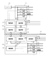
- FIG. 2 shows the configuration of the first and second radio apparatuses 14 and 18.
- the first wireless device 14 is supplied with power from the battery 12 via the relay box 13.
- the first wireless device 14 includes a power supply control unit 21, a communication control unit 22, a wireless power feeding unit 23, and a wireless communication unit 24.
- the second wireless device 18 includes a power control unit 25, a communication control unit 26, a wireless power feeding unit 27, and a wireless communication unit 28.
- the power control unit 21 of the first wireless device 14 controls the opening and closing of the relay 29 in the relay box 13 based on the control signal output from the wireless communication unit 24.
- the relay box 13 supplies electric power supplied from the battery 12 to electric devices in the engine room 11.
- the relay box 13 is provided with an ignition device that requires power when the ignition switch is turned on, an accessory device that is supplied with power other than when the ignition switch is turned on, an illuminator, and a warning sound. Supply power to equipment, engine related equipment, etc.
- the power supply control unit 21 controls the opening / closing of each relay 29 to control the power supply to each device.
- the communication control unit 22 of the first wireless device 14 is connected to the first ECU 15 and communication devices such as a device that performs CAN communication and a device that performs LIN communication, and between these devices and the wireless communication unit 24. Acts as a buffer.
- the wireless communication unit 24 of the first wireless device 14 can bidirectionally communicate with the wireless communication unit 28 of the second wireless device 18 by a wireless communication method such as NFC or Transferjet.
- the wireless power supply unit 23 of the first wireless device 14 can wirelessly supply power to the wireless power supply unit 27 of the second wireless device 18. That is, in the present embodiment, the wireless power supply unit 23 operates as a power transmission unit, and the wireless power supply unit 27 operates as a power reception unit.
- Examples of the wireless power feeding method that can be adopted in the present invention include an electromagnetic induction method and an electric field coupling method.
- the power supplied to the wireless power feeding unit 27 is, via each relay 30, an ignition device that requires power when the ignition switch is turned on, an accessory device that is supplied with power other than when the ignition switch is turned on, and It is supplied to electrical equipment in the passenger compartment 16 such as a door lock device and a seat adjustment device.
- the power control unit 25 of the second wireless device 18 controls the opening and closing of the relay 30 based on the control signal output from the wireless communication unit 28. Therefore, the power supply control unit 25 controls the opening / closing of each relay 30 to control the power supply to each device.
- the communication control unit 26 of the second wireless device 18 is connected to the second ECU 19 and communication devices such as a device that performs CAN communication and a device that performs LIN communication, and between these devices and the wireless communication unit 28. Acts as a buffer.
- the partition wall 17 between the first wireless device 14 and the second wireless device 18 is provided with a non-metal portion 31 such as a synthetic resin plate, and the first wireless device 14 and the first wireless device 14 Wireless power feeding and wireless communication with the second wireless device 18 are not disturbed.
- the non-metal part 31 has a through hole 32 at a position sandwiched between the wireless power feeding parts 23 and 27 and a position sandwiched between the wireless communication parts 24 and 28. You may have. Only the through holes 32 may be provided in the partition wall 17 without providing the non-metal portion 31.
- the power supplied from the battery 12 is supplied to each device in the engine room 11 via the relay box 13 controlled by the power supply control unit 21.
- the power supplied from the battery 12 is also supplied to the first wireless device 14 via the relay box 13, and the power is supplied from the wireless power supply unit 23 of the first wireless device 14 to the wireless power supply unit 27 of the second wireless device. Used for wireless power feeding. Then, power is supplied from the wireless power feeding unit 27 to each device in the passenger compartment 16.
- Communication signals output from the first ECU 15 and other devices in the engine room 11 are transmitted from the communication control unit 22 of the first wireless device 14 to the wireless communication unit 24 and the wireless communication unit 28 of the second wireless device 18. Further, it is transmitted to the communication control unit 26 and transferred from the communication control unit 26 to the second ECU 19 and other devices.
- communication signals output from the second ECU 19 and other devices in the passenger compartment 16 are transmitted from the communication control unit 26 of the second wireless device 18 to the wireless communication unit 28 and the wireless signal of the first wireless device 14.
- the data is transmitted to the communication unit 24 and further to the communication control unit 22, and transferred from the communication control unit 22 to the first ECU 15 and other devices.
- the above-described automobile power distribution device has the following effects. (1) Power can be supplied from the battery 12 in the engine room 11 to the electrical equipment in the vehicle compartment 16 via the wireless power feeding units 23 and 24. (2) It is not necessary to form a through hole for penetrating the wire harness in the partition wall 17 separating the engine room 11 and the vehicle compartment 16. Therefore, it is possible to prevent rainwater from entering the vehicle compartment 16 from the engine room 11. (3) Since there is no need to form a through hole, it is not necessary to prepare a grommet for each vehicle type. There is no need to form through holes with different diameters for each vehicle type. (4) Since the wire harness is not passed through the through hole, it is not necessary to bend the wire harness near the through hole.
- the wiring work of the wire harness extending from the first wireless device 14 and the second wireless device 18 in the vicinity of the partition wall 17 can be easily performed.
- a communication signal between the electric device in the engine room 11 and the electric device in the vehicle compartment 16 can be transmitted via the wireless communication units 24 and 28. Therefore, it is not necessary to penetrate the wire harness for transmitting the communication signal to the partition wall 17.
- the portion of the partition wall 17 between the first wireless device 14 and the second wireless device 18 is composed of the non-metal part 31, the first wireless device 14 and the second wireless device 18 Wireless power feeding and wireless communication can be further stabilized.
- the partition wall 17 has the through hole 32 at a position sandwiched between the wireless power feeding units 23 and 27 and a position sandwiched between the wireless communication units 24 and 28, the wireless power feeding and the wireless communication are more stable. Can be made.
- the above embodiment may be modified as follows.
- the relay 30 may be provided not in the second wireless device 18 but in a relay box or the like outside the second wireless device 18.
Landscapes
- Engineering & Computer Science (AREA)
- Computer Networks & Wireless Communication (AREA)
- Power Engineering (AREA)
- Mechanical Engineering (AREA)
- Charge And Discharge Circuits For Batteries Or The Like (AREA)
- Cable Accessories (AREA)
- Near-Field Transmission Systems (AREA)
- Installation Of Indoor Wiring (AREA)
- Selective Calling Equipment (AREA)
Abstract
Provided is an electricity distribution device for an automobile, comprising: a first wireless device 14 which is provided with a first wireless power supply unit and is disposed in an engine room 11, and to which electrical power is supplied from a battery 12 disposed in the engine room 11; a second wireless device 18 which is provided with a second wireless power supply unit and is disposed in a vehicle interior 16; and a power distribution device 20 that supplies electrical power supplied to the second wireless device to an electrical apparatus in the vehicle interior 16. The first and second wireless power supply units are configured so as to supply power wirelessly from the first wireless device 14 to the second wireless device 18 and the first and second wireless devices 14, 18 are disposed so as to be near a partition wall 17 between the engine room 11 and the vehicle interior 16 or in contact with the partition wall 17.
Description
本発明は、自動車において隔壁で隔てられた空間、例えば車室とエンジンルームとの間で、電気的接続を可能にする配電装置に関するものである。
The present invention relates to a power distribution device that enables an electrical connection between a space separated by a partition wall in an automobile, for example, a vehicle compartment and an engine room.
従来の自動車用配電装置の一例を図4に示す。エンジンルーム1内において、バッテリー2はリレーボックス3に接続される。リレーボックス3は多数本の電源供給線を纏めたワイヤーハーネス4を介して、車室5内に配設された電気接続箱6に接続される。
An example of a conventional automobile power distribution device is shown in FIG. In the engine room 1, the battery 2 is connected to the relay box 3. The relay box 3 is connected to an electrical connection box 6 disposed in the passenger compartment 5 via a wire harness 4 in which a large number of power supply lines are collected.
電気接続箱6には、多数の電気機器が接続される。各電気機器には、バッテリー2からリレーボックス3、ワイヤーハーネス4、そして電気接続箱6を介して所要の電力が供給される。
A large number of electrical devices are connected to the electrical junction box 6. Each electric device is supplied with required power from the battery 2 via the relay box 3, the wire harness 4, and the electric connection box 6.
また、リレーボックス3からエンジンルーム1内の電気機器にも所要の電力が供給される。
エンジンルーム1内にはECU7が配設され、エンジンルーム1内に配設される電気機器の動作を制御する。また、ECU7は車室5内に配設されるECU8にワイヤーハーネス9を介して接続され、ECU8との通信に基づいてエンジンルーム1内の電気機器が車室5内の電気機器と連携して動作するように制御する。 In addition, the required power is supplied from the relay box 3 to the electrical equipment in the engine room 1.
An ECU 7 is disposed in the engine room 1 and controls the operation of electrical equipment disposed in the engine room 1. The ECU 7 is connected to an ECU 8 disposed in thepassenger compartment 5 via a wire harness 9, and the electrical equipment in the engine room 1 is linked with the electrical equipment in the passenger compartment 5 based on communication with the ECU 8. Control to work.
エンジンルーム1内にはECU7が配設され、エンジンルーム1内に配設される電気機器の動作を制御する。また、ECU7は車室5内に配設されるECU8にワイヤーハーネス9を介して接続され、ECU8との通信に基づいてエンジンルーム1内の電気機器が車室5内の電気機器と連携して動作するように制御する。 In addition, the required power is supplied from the relay box 3 to the electrical equipment in the engine room 1.
An ECU 7 is disposed in the engine room 1 and controls the operation of electrical equipment disposed in the engine room 1. The ECU 7 is connected to an ECU 8 disposed in the
車室5内に配設されたECU8は、ECU7との通信に基づいて車室5内の電気機器をエンジンルーム1内の電気機器と連携するように制御する。
ワイヤーハーネス4,9は、エンジンルーム1と車室5との間の隔壁10に形成された貫通孔に挿通されている。エンジンルーム1と車室5との間の気密性及び水密性を確保するために、ワイヤーハーネス4,9を挿通したグロメット10aが貫通孔に嵌着されている。 The ECU 8 disposed in thepassenger compartment 5 controls the electrical equipment in the passenger compartment 5 to cooperate with the electrical equipment in the engine compartment 1 based on communication with the ECU 7.
The wire harnesses 4 and 9 are inserted through through holes formed in thepartition wall 10 between the engine room 1 and the vehicle compartment 5. In order to ensure airtightness and watertightness between the engine room 1 and the vehicle compartment 5, a grommet 10a through which the wire harnesses 4 and 9 are inserted is fitted into the through hole.
ワイヤーハーネス4,9は、エンジンルーム1と車室5との間の隔壁10に形成された貫通孔に挿通されている。エンジンルーム1と車室5との間の気密性及び水密性を確保するために、ワイヤーハーネス4,9を挿通したグロメット10aが貫通孔に嵌着されている。 The ECU 8 disposed in the
The wire harnesses 4 and 9 are inserted through through holes formed in the
上記のような配電装置では、ワイヤーハーネス4,9を挿通したグロメット10aを隔壁10の貫通孔に取り付けるため、エンジンルーム1内の雨水がワイヤーハーネス4,9をつたって車室5内に侵入することがある。
In the power distribution device as described above, the grommet 10a through which the wire harnesses 4 and 9 are inserted is attached to the through holes of the partition wall 10, so that rainwater in the engine room 1 enters the vehicle compartment 5 through the wire harnesses 4 and 9. Sometimes.
近年の自動車では、使用される電気機器の増加にともなって、ワイヤーハーネスとして纏められる電線本数が増大している。このため、ワイヤーハーネスの直径が増大して、配索時のワイヤーハーネスの屈曲作業が困難となり、配索作業が煩雑となる。
In recent automobiles, the number of electric wires collected as a wire harness is increasing with an increase in the number of electric devices used. For this reason, the diameter of a wire harness increases, the bending work of the wire harness at the time of wiring becomes difficult, and wiring work becomes complicated.
また、ワイヤーハーネスの直径の増大にともなって隔壁10に形成する貫通孔の直径を大きくすることは好ましくない。従って、ワイヤーハーネスとして纏められる電線の本数には限りがある。
Also, it is not preferable to increase the diameter of the through hole formed in the partition wall 10 as the diameter of the wire harness increases. Therefore, there is a limit to the number of wires that can be collected as a wire harness.
特許文献1には、防水機能を備えたグロメットが開示されている。しかし、防水機能が確実に作用しない場合がある。また、車種毎にワイヤーハーネスの直径が異なるため、その直径に応じたグロメットを車種毎に設計し、且つ製造する必要がある。このことは部品コストを上昇させる。
Patent Document 1 discloses a grommet having a waterproof function. However, the waterproof function may not work reliably. Moreover, since the diameter of a wire harness differs for every vehicle model, it is necessary to design and manufacture the grommet according to the diameter for every vehicle model. This increases the part cost.
本発明の目的は、車室内への雨水の侵入を確実に防止し得る自動車用配電装置を提供することにある。
It is an object of the present invention to provide an automobile power distribution device that can reliably prevent rainwater from entering the passenger compartment.
本発明の一態様によれば、自動車用配電装置は、第一の無線給電部を備えるとともにエンジンルーム内に配置される第一の無線装置であって、前記エンジンルーム内に配置されたバッテリーから電力が供給される第一の無線装置と、第二の無線給電部を備えるとともに車室内に配置される第二の無線装置と、前記第二の無線装置に供給された電力を前記車室内に配置された電気機器に供給する電力分配装置とを備える。前記第一及び第二の無線給電部は、前記第一の無線装置から前記第二の無線装置に無線給電を行うように構成されており、前記第一及び第二の無線装置は、前記エンジンルームと前記車室との間の隔壁に近接して、又は前記隔壁に接触するように配置される。
According to one aspect of the present invention, an automotive power distribution device includes a first wireless power feeding unit and is a first wireless device disposed in an engine room, the battery being disposed in the engine room. A first wireless device to which power is supplied, a second wireless device having a second wireless power feeding unit and disposed in the vehicle interior, and power supplied to the second wireless device to the vehicle interior And a power distribution device for supplying electric power to the arranged electrical equipment. The first and second wireless power feeding units are configured to perform wireless power feeding from the first wireless device to the second wireless device, and the first and second wireless devices are configured to transmit the engine. It arrange | positions so that the partition between a room and the said vehicle interior may be adjoined, or may contact the said partition.
この構成により、隔壁を貫通するワイヤーハーネスを用いることなく、バッテリーから車室内の電気機器に電力が供給可能となる。
上記の自動車用配電装置において、前記第一の無線装置及び前記第二の無線装置は、それぞれ第一の無線通信部及び第二の無線通信部を備え、前記第一及び第二の無線通信部は、前記エンジンルーム内に配置された電気機器と前記車室内の前記電気機器との間の通信信号を無線で送受信するように構成されていることが好ましい。 With this configuration, it is possible to supply electric power from the battery to the electric equipment in the vehicle interior without using a wire harness that penetrates the partition wall.
In the above vehicle power distribution device, the first wireless device and the second wireless device each include a first wireless communication unit and a second wireless communication unit, and the first and second wireless communication units, respectively. Is preferably configured to wirelessly transmit and receive communication signals between the electrical equipment disposed in the engine room and the electrical equipment in the vehicle compartment.
この構成により、隔壁を貫通するワイヤーハーネスを用いることなく、エンジン内の電気機器と車室内の電気機器との間での通信が可能となる。
上記の自動車用配電装置において、前記第一の無線装置と前記第二の無線装置が、前記隔壁を挟んで相対向する位置に設置され、前記隔壁のうち、前記第一の無線装置と前記第二の無線装置との間に挟まれる部分が非金属部からなることが好ましい。 With this configuration, communication between the electric device in the engine and the electric device in the vehicle compartment can be performed without using a wire harness that penetrates the partition wall.
In the above-described automobile power distribution device, the first wireless device and the second wireless device are installed at positions facing each other across the partition, and the first wireless device and the first of the partitions are It is preferable that the portion sandwiched between the two wireless devices is made of a non-metallic portion.
この構成により、第一の無線装置と第二の無線装置との間の無線給電及び無線通信が安定する。
上記の自動車用配電装置において、前記第一及び第二の無線給電部が前記隔壁を挟んで相対向する位置に配置され、前記第一及び第二の無線通信部が前記隔壁を挟んで相対向する位置に配置され、かつ、前記隔壁は、前記第一及び第二の無線給電部の間の位置及び前記第一及び第二の無線通信部の間の位置にそれぞれ透孔を有することが好ましい。 With this configuration, wireless power feeding and wireless communication between the first wireless device and the second wireless device are stabilized.
In the above-described automobile power distribution device, the first and second wireless power feeding units are arranged at positions facing each other with the partition wall interposed therebetween, and the first and second wireless communication units are opposed to each other with the partition wall interposed therebetween. It is preferable that the partition wall has a through hole at a position between the first and second wireless power feeding units and a position between the first and second wireless communication units. .
この構成により、第一の無線装置と第二の無線装置との間の無線給電及び無線通信が安定する。
上記の自動車用配電装置において、前記第一の無線装置は、前記エンジンルーム内の前記電気機器と前記第一の無線通信部との間に介在されて通信信号を送受信する第一の通信制御部を備え、前記第二の無線装置は、前記車室内の前記電気機器と前記第二の無線通信部との間に介在されて通信信号を送受信する第二の通信制御部を備えることが好ましい。 With this configuration, wireless power feeding and wireless communication between the first wireless device and the second wireless device are stabilized.
In the above vehicle power distribution device, the first wireless device is a first communication control unit that is interposed between the electric device in the engine room and the first wireless communication unit and transmits and receives communication signals. Preferably, the second wireless device includes a second communication control unit that is interposed between the electric device in the vehicle interior and the second wireless communication unit and transmits and receives communication signals.
この構成により、エンジンルーム内の電気機器と第一の無線通信部との通信が第一の通信制御部で管理され、車室内の電気機器と第二の無線通信部との通信が第二の通信制御部で管理される。
With this configuration, the communication between the electric device in the engine room and the first wireless communication unit is managed by the first communication control unit, and the communication between the electric device in the vehicle interior and the second wireless communication unit is the second. Managed by the communication control unit.
本発明の別の態様によれば、自動車用配電装置を備える自動車が提供される。前記自動車は、エンジンルーム、車室、及び前記エンジンルームと前記車室との間の隔壁を有するボディを備え、前記自動車用配電装置は、第一の無線給電部を備えるとともに前記エンジンルーム内に配置された第一の無線装置であって、前記エンジンルーム内に配置されたバッテリーから電力が供給される第一の無線装置と、第二の無線給電部を備えるとともに前記車室内に配置された第二の無線装置と、前記第二の無線装置に供給された電力を前記車室内に配置された電気機器に供給する電力分配装置とを備え、前記第一及び第二の無線給電部は、前記第一の無線装置から前記第二の無線装置に無線給電を行うように構成されており、前記第一及び第二の無線装置は、前記隔壁に近接して、又は前記隔壁に接触するように配置されている。
According to another aspect of the present invention, an automobile including an automobile power distribution device is provided. The automobile includes an engine room, a vehicle compartment, and a body having a partition wall between the engine room and the vehicle compartment, and the automobile power distribution device includes a first wireless power feeding unit and is disposed in the engine room. A first wireless device arranged, wherein the first wireless device is supplied with electric power from a battery arranged in the engine room, and has a second wireless power feeding unit and is arranged in the vehicle interior. A second wireless device; and a power distribution device that supplies electric power supplied to the second wireless device to an electrical device disposed in the vehicle interior, wherein the first and second wireless power feeding units are The first wireless device is configured to perform wireless power feeding from the first wireless device to the second wireless device, and the first and second wireless devices are adjacent to or in contact with the partition wall. Is located in
本発明の自動車用配電装置によれば、車室内への雨水の侵入を確実に防止することができる。
According to the automobile power distribution device of the present invention, it is possible to reliably prevent rainwater from entering the vehicle compartment.
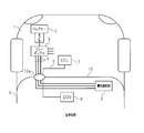
以下、自動車用配電装置の一実施形態を図面に従って説明する。図1に示すように、エンジンルーム11内において、バッテリー12はリレーボックス13に接続される。リレーボックス13から第一の無線装置14にバッテリー12の出力電力が供給される。リレーボックス13からエンジンルーム11内の電気機器にも所要の電力が供給される。
Hereinafter, an embodiment of an automobile power distribution device will be described with reference to the drawings. As shown in FIG. 1, the battery 12 is connected to a relay box 13 in the engine room 11. The output power of the battery 12 is supplied from the relay box 13 to the first wireless device 14. Necessary power is also supplied from the relay box 13 to the electrical equipment in the engine room 11.
エンジンルーム11内には第一のECU15が配設される。第一のECU15は、エンジンルーム11内に配設される電気機器の動作を制御するとともに、第一の無線装置14と通信信号の送受信を行う。
A first ECU 15 is disposed in the engine room 11. The first ECU 15 controls the operation of the electrical equipment disposed in the engine room 11 and transmits / receives communication signals to / from the first wireless device 14.
エンジンルーム11内において、第一の無線装置14はエンジンルーム11と車室16を隔てる隔壁17に近接して、又は隔壁17に接触するように配設されている。
車室16内において、隔壁17を隔てて第一の無線装置14と対向する位置には、第二の無線装置18が隔壁17に近接して、又は隔壁17に接触するように配設されている。第一の無線装置14はバッテリー12から供給される電力を第二の無線装置18に無線給電可能であるとともに、第二の無線装置18との間で種々の通信信号を送受信可能である。 In theengine room 11, the first wireless device 14 is disposed adjacent to or in contact with the partition wall 17 that separates the engine room 11 and the vehicle compartment 16.
In thepassenger compartment 16, a second wireless device 18 is disposed near the partition wall 17 or in contact with the partition wall 17 at a position facing the first wireless device 14 across the partition wall 17. Yes. The first wireless device 14 can wirelessly feed the power supplied from the battery 12 to the second wireless device 18 and can transmit and receive various communication signals to and from the second wireless device 18.
車室16内において、隔壁17を隔てて第一の無線装置14と対向する位置には、第二の無線装置18が隔壁17に近接して、又は隔壁17に接触するように配設されている。第一の無線装置14はバッテリー12から供給される電力を第二の無線装置18に無線給電可能であるとともに、第二の無線装置18との間で種々の通信信号を送受信可能である。 In the
In the
第二の無線装置18には、車室16内に配設される第二のECU19と、電力分配装置(本実施形態では電気接続箱20)が接続されている。第二の無線装置18に供給された電力が電気接続箱20に供給され、その電力は車室16内に配設される多数の電気機器に更に供給される。
The second wireless device 18 is connected to a second ECU 19 disposed in the passenger compartment 16 and a power distribution device (electrical connection box 20 in the present embodiment). The electric power supplied to the second wireless device 18 is supplied to the electric junction box 20, and the electric power is further supplied to a number of electric devices arranged in the passenger compartment 16.
第二のECU19は、第一及び第二の無線装置14,18を介して第一のECU15と通信し、エンジンルーム11内の電気機器及び車室16内の電気機器を制御する。
図2は、第一及び第二の無線装置14,18の構成を示す。第一の無線装置14には、バッテリー12からリレーボックス13を介して電源が供給される。第一の無線装置14は、電源制御部21と、通信制御部22と、無線給電部23と、無線通信部24を備えている。第二の無線装置18も同様に、電源制御部25と、通信制御部26と、無線給電部27と、無線通信部28を備えている。 Thesecond ECU 19 communicates with the first ECU 15 via the first and second wireless devices 14 and 18 to control the electric devices in the engine room 11 and the electric devices in the vehicle compartment 16.
FIG. 2 shows the configuration of the first and second radio apparatuses 14 and 18. The first wireless device 14 is supplied with power from the battery 12 via the relay box 13. The first wireless device 14 includes a power supply control unit 21, a communication control unit 22, a wireless power feeding unit 23, and a wireless communication unit 24. Similarly, the second wireless device 18 includes a power control unit 25, a communication control unit 26, a wireless power feeding unit 27, and a wireless communication unit 28.
図2は、第一及び第二の無線装置14,18の構成を示す。第一の無線装置14には、バッテリー12からリレーボックス13を介して電源が供給される。第一の無線装置14は、電源制御部21と、通信制御部22と、無線給電部23と、無線通信部24を備えている。第二の無線装置18も同様に、電源制御部25と、通信制御部26と、無線給電部27と、無線通信部28を備えている。 The
FIG. 2 shows the configuration of the first and
第一の無線装置14の電源制御部21は、無線通信部24から出力される制御信号に基づいてリレーボックス13内のリレー29を開閉制御する。
リレーボックス13は、エンジンルーム11内の電気機器にバッテリー12から供給される電力を供給する。また、リレーボックス13は各リレー29を介して、イグニッションスイッチのオン動作時に電力を必要とするイグニッション機器、イグニッションスイッチのオン動作時以外にも電力が供給されるアクセサリー機器、並びに照明器、警音器、エンジン関連機器等に電力を供給する。 Thepower control unit 21 of the first wireless device 14 controls the opening and closing of the relay 29 in the relay box 13 based on the control signal output from the wireless communication unit 24.
Therelay box 13 supplies electric power supplied from the battery 12 to electric devices in the engine room 11. In addition, the relay box 13 is provided with an ignition device that requires power when the ignition switch is turned on, an accessory device that is supplied with power other than when the ignition switch is turned on, an illuminator, and a warning sound. Supply power to equipment, engine related equipment, etc.
リレーボックス13は、エンジンルーム11内の電気機器にバッテリー12から供給される電力を供給する。また、リレーボックス13は各リレー29を介して、イグニッションスイッチのオン動作時に電力を必要とするイグニッション機器、イグニッションスイッチのオン動作時以外にも電力が供給されるアクセサリー機器、並びに照明器、警音器、エンジン関連機器等に電力を供給する。 The
The
従って、電源制御部21による各リレー29の開閉制御により、各機器への電力の供給が開閉制御される。
第一の無線装置14の通信制御部22は、第一のECU15、並びにCAN通信を行う機器、LIN通信を行う機器等の通信機器に接続され、これらの機器と無線通信部24との間のバッファとして動作する。 Therefore, the powersupply control unit 21 controls the opening / closing of each relay 29 to control the power supply to each device.
Thecommunication control unit 22 of the first wireless device 14 is connected to the first ECU 15 and communication devices such as a device that performs CAN communication and a device that performs LIN communication, and between these devices and the wireless communication unit 24. Acts as a buffer.
第一の無線装置14の通信制御部22は、第一のECU15、並びにCAN通信を行う機器、LIN通信を行う機器等の通信機器に接続され、これらの機器と無線通信部24との間のバッファとして動作する。 Therefore, the power
The
第一の無線装置14の無線通信部24は、第二の無線装置18の無線通信部28と例えばNFCあるいはTransferjet等の無線通信方式により双方向に通信可能である。
第一の無線装置14の無線給電部23は、第二の無線装置18の無線給電部27に無線給電可能である。すなわち、本実施形態において、無線給電部23は送電部として動作し、無線給電部27は受電部として動作する。本発明において採用することができる無線給電方式には、例えば電磁誘導方式及び電界結合方式が挙げられる。 Thewireless communication unit 24 of the first wireless device 14 can bidirectionally communicate with the wireless communication unit 28 of the second wireless device 18 by a wireless communication method such as NFC or Transferjet.
The wirelesspower supply unit 23 of the first wireless device 14 can wirelessly supply power to the wireless power supply unit 27 of the second wireless device 18. That is, in the present embodiment, the wireless power supply unit 23 operates as a power transmission unit, and the wireless power supply unit 27 operates as a power reception unit. Examples of the wireless power feeding method that can be adopted in the present invention include an electromagnetic induction method and an electric field coupling method.
第一の無線装置14の無線給電部23は、第二の無線装置18の無線給電部27に無線給電可能である。すなわち、本実施形態において、無線給電部23は送電部として動作し、無線給電部27は受電部として動作する。本発明において採用することができる無線給電方式には、例えば電磁誘導方式及び電界結合方式が挙げられる。 The
The wireless
無線給電部27に供給された電力は、各リレー30を介して、イグニッションスイッチのオン動作時に電力を必要とするイグニッション機器、イグニッションスイッチのオン動作時以外にも電力が供給されるアクセサリー機器、並びにドアロック装置、シート調節装置等の、車室16内の電気機器に供給される。
The power supplied to the wireless power feeding unit 27 is, via each relay 30, an ignition device that requires power when the ignition switch is turned on, an accessory device that is supplied with power other than when the ignition switch is turned on, and It is supplied to electrical equipment in the passenger compartment 16 such as a door lock device and a seat adjustment device.
第二の無線装置18の電源制御部25は、無線通信部28から出力される制御信号に基づいてリレー30を開閉制御する。従って、電源制御部25による各リレー30の開閉制御により、各機器への電力の供給が開閉制御される。
The power control unit 25 of the second wireless device 18 controls the opening and closing of the relay 30 based on the control signal output from the wireless communication unit 28. Therefore, the power supply control unit 25 controls the opening / closing of each relay 30 to control the power supply to each device.
第二の無線装置18の通信制御部26は、第二のECU19、並びにCAN通信を行う機器、LIN通信を行う機器等の通信機器に接続され、これらの機器と無線通信部28との間のバッファとして動作する。
The communication control unit 26 of the second wireless device 18 is connected to the second ECU 19 and communication devices such as a device that performs CAN communication and a device that performs LIN communication, and between these devices and the wireless communication unit 28. Acts as a buffer.
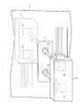
図3に示すように、第一の無線装置14と第二の無線装置18との間の隔壁17には、合成樹脂板等の非金属部31が設けられ、第一の無線装置14と第二の無線装置18との間の無線給電及び無線通信を阻害しないようにしている。
As shown in FIG. 3, the partition wall 17 between the first wireless device 14 and the second wireless device 18 is provided with a non-metal portion 31 such as a synthetic resin plate, and the first wireless device 14 and the first wireless device 14 Wireless power feeding and wireless communication with the second wireless device 18 are not disturbed.
無線給電効率及び通信効率がさらに向上するように、非金属部31は、無線給電部23,27の間に挟まれた位置及び無線通信部24,28の間に挟まれた位置に透孔32を有してもよい。非金属部31を設けることなく、隔壁17に透孔32だけを設けてもよい。
In order to further improve the wireless power feeding efficiency and the communication efficiency, the non-metal part 31 has a through hole 32 at a position sandwiched between the wireless power feeding parts 23 and 27 and a position sandwiched between the wireless communication parts 24 and 28. You may have. Only the through holes 32 may be provided in the partition wall 17 without providing the non-metal portion 31.
隔壁17が透孔32を有する場合、透孔32を覆うように隔壁17の両面上に第一及び第二の無線装置14,18を取り付けることにより、エンジンルーム11から車室16内への雨水の侵入を防止可能である。
When the partition wall 17 has the through-hole 32, rainwater from the engine room 11 to the vehicle interior 16 can be obtained by attaching the first and second wireless devices 14 and 18 on both surfaces of the partition wall 17 so as to cover the through-hole 32. Can be prevented.
次に、上記実施形態の自動車用配電装置の作用を説明する。
バッテリー12から供給される電力は、電源制御部21によって制御されるリレーボックス13を介してエンジンルーム11内の各機器に供給される。 Next, the operation of the automobile power distribution device of the above embodiment will be described.
The power supplied from thebattery 12 is supplied to each device in the engine room 11 via the relay box 13 controlled by the power supply control unit 21.
バッテリー12から供給される電力は、電源制御部21によって制御されるリレーボックス13を介してエンジンルーム11内の各機器に供給される。 Next, the operation of the automobile power distribution device of the above embodiment will be described.
The power supplied from the
バッテリー12から供給される電力は、リレーボックス13を介して第一の無線装置14にも供給され、第一の無線装置14の無線給電部23から第二の無線装置の無線給電部27への無線給電に利用される。そして、無線給電部27から車室16内の各機器に電力が供給される。
The power supplied from the battery 12 is also supplied to the first wireless device 14 via the relay box 13, and the power is supplied from the wireless power supply unit 23 of the first wireless device 14 to the wireless power supply unit 27 of the second wireless device. Used for wireless power feeding. Then, power is supplied from the wireless power feeding unit 27 to each device in the passenger compartment 16.
エンジンルーム11内の第一のECU15及び他の機器から出力される通信信号は、第一の無線装置14の通信制御部22から、無線通信部24、第二の無線装置18の無線通信部28、さらに通信制御部26へと伝送され、通信制御部26から第二のECU19及び他の機器に転送される。
Communication signals output from the first ECU 15 and other devices in the engine room 11 are transmitted from the communication control unit 22 of the first wireless device 14 to the wireless communication unit 24 and the wireless communication unit 28 of the second wireless device 18. Further, it is transmitted to the communication control unit 26 and transferred from the communication control unit 26 to the second ECU 19 and other devices.
同様に、車室16内の第二のECU19及び他の機器から出力される通信信号は、第二の無線装置18の通信制御部26から、無線通信部28、第一の無線装置14の無線通信部24、さらに通信制御部22へと伝送され、通信制御部22から第一のECU15及び他の機器に転送される。
Similarly, communication signals output from the second ECU 19 and other devices in the passenger compartment 16 are transmitted from the communication control unit 26 of the second wireless device 18 to the wireless communication unit 28 and the wireless signal of the first wireless device 14. The data is transmitted to the communication unit 24 and further to the communication control unit 22, and transferred from the communication control unit 22 to the first ECU 15 and other devices.
上記の自動車用配電装置は、下記の効果を奏する。
(1)エンジンルーム11内のバッテリー12から無線給電部23,24を介して車室16内の電気機器に電源を供給することができる。
(2)エンジンルーム11と車室16を隔てる隔壁17に、ワイヤーハーネスを貫通させるための貫通孔を形成する必要がない。従って、エンジンルーム11から車室16内への雨水の侵入を未然に防止することができる。
(3)貫通孔を形成する必要がないので、車種毎にグロメットを用意する必要がない。車種毎に異なる径の貫通孔を形成する必要もない。
(4)貫通孔にワイヤーハーネスを貫通させないので、貫通孔の付近でワイヤーハーネスを屈曲させる必要がない。従って、隔壁17近傍で第一の無線装置14及び第二の無線装置18から延びるワイヤーハーネスの配索作業を容易に行うことができる。
(5)エンジンルーム11内の電気機器と車室16内の電気機器との間の通信信号を、無線通信部24,28を介して伝送することができる。従って、隔壁17に通信信号を伝送するためのワイヤーハーネスを貫通させる必要がない。
(6)隔壁17のうち、第一の無線装置14と第二の無線装置18との間の部分が非金属部31からなる場合、第一の無線装置14と第二の無線装置18との間の無線給電及び無線通信をより安定させることができる。
(7)隔壁17が、無線給電部23,27の間に挟まれた位置及び無線通信部24,28の間に挟まれた位置に透孔32を有する場合、無線給電及び無線通信をより安定させることができる。 The above-described automobile power distribution device has the following effects.
(1) Power can be supplied from thebattery 12 in the engine room 11 to the electrical equipment in the vehicle compartment 16 via the wireless power feeding units 23 and 24.
(2) It is not necessary to form a through hole for penetrating the wire harness in thepartition wall 17 separating the engine room 11 and the vehicle compartment 16. Therefore, it is possible to prevent rainwater from entering the vehicle compartment 16 from the engine room 11.
(3) Since there is no need to form a through hole, it is not necessary to prepare a grommet for each vehicle type. There is no need to form through holes with different diameters for each vehicle type.
(4) Since the wire harness is not passed through the through hole, it is not necessary to bend the wire harness near the through hole. Therefore, the wiring work of the wire harness extending from thefirst wireless device 14 and the second wireless device 18 in the vicinity of the partition wall 17 can be easily performed.
(5) A communication signal between the electric device in theengine room 11 and the electric device in the vehicle compartment 16 can be transmitted via the wireless communication units 24 and 28. Therefore, it is not necessary to penetrate the wire harness for transmitting the communication signal to the partition wall 17.
(6) When the portion of thepartition wall 17 between the first wireless device 14 and the second wireless device 18 is composed of the non-metal part 31, the first wireless device 14 and the second wireless device 18 Wireless power feeding and wireless communication can be further stabilized.
(7) When thepartition wall 17 has the through hole 32 at a position sandwiched between the wireless power feeding units 23 and 27 and a position sandwiched between the wireless communication units 24 and 28, the wireless power feeding and the wireless communication are more stable. Can be made.
(1)エンジンルーム11内のバッテリー12から無線給電部23,24を介して車室16内の電気機器に電源を供給することができる。
(2)エンジンルーム11と車室16を隔てる隔壁17に、ワイヤーハーネスを貫通させるための貫通孔を形成する必要がない。従って、エンジンルーム11から車室16内への雨水の侵入を未然に防止することができる。
(3)貫通孔を形成する必要がないので、車種毎にグロメットを用意する必要がない。車種毎に異なる径の貫通孔を形成する必要もない。
(4)貫通孔にワイヤーハーネスを貫通させないので、貫通孔の付近でワイヤーハーネスを屈曲させる必要がない。従って、隔壁17近傍で第一の無線装置14及び第二の無線装置18から延びるワイヤーハーネスの配索作業を容易に行うことができる。
(5)エンジンルーム11内の電気機器と車室16内の電気機器との間の通信信号を、無線通信部24,28を介して伝送することができる。従って、隔壁17に通信信号を伝送するためのワイヤーハーネスを貫通させる必要がない。
(6)隔壁17のうち、第一の無線装置14と第二の無線装置18との間の部分が非金属部31からなる場合、第一の無線装置14と第二の無線装置18との間の無線給電及び無線通信をより安定させることができる。
(7)隔壁17が、無線給電部23,27の間に挟まれた位置及び無線通信部24,28の間に挟まれた位置に透孔32を有する場合、無線給電及び無線通信をより安定させることができる。 The above-described automobile power distribution device has the following effects.
(1) Power can be supplied from the
(2) It is not necessary to form a through hole for penetrating the wire harness in the
(3) Since there is no need to form a through hole, it is not necessary to prepare a grommet for each vehicle type. There is no need to form through holes with different diameters for each vehicle type.
(4) Since the wire harness is not passed through the through hole, it is not necessary to bend the wire harness near the through hole. Therefore, the wiring work of the wire harness extending from the
(5) A communication signal between the electric device in the
(6) When the portion of the
(7) When the
上記実施形態は以下のように変更してもよい。
・リレー30は、第二の無線装置18の内部ではなく、第二の無線装置18の外部のリレーボックス等に設けてもよい。 The above embodiment may be modified as follows.
Therelay 30 may be provided not in the second wireless device 18 but in a relay box or the like outside the second wireless device 18.
・リレー30は、第二の無線装置18の内部ではなく、第二の無線装置18の外部のリレーボックス等に設けてもよい。 The above embodiment may be modified as follows.
The
上記の実施形態は例示を意図したものであり、本発明は上記実施形態に限定されるものではない。開示された例示的な実施形態に対し、本発明の主旨及び範囲から逸脱することなく、様々な代替、変更及び変形が可能である。たとえば、本発明の主題は開示された特定の実施形態の全ての特徴よりも少ない特徴に存在する可能性がある。そのため、請求の範囲は詳細な説明に組み込まれ、各請求項はそれ自体で、別個の実施形態を主張する。本発明の範囲は、このような代替形態、変更形態および変形形態のすべてを、それらのすべての均等物とともに、特許請求の範囲内に包含するように意図されている。
The above embodiment is intended to be illustrative, and the present invention is not limited to the above embodiment. Various alternatives, modifications, and variations may be made to the disclosed exemplary embodiments without departing from the spirit and scope of the invention. For example, the subject matter of the present invention may reside in fewer features than all the features of the particular embodiment disclosed. Thus, the following claims are hereby incorporated into the Detailed Description, with each claim standing on its own as a separate embodiment. The scope of the present invention is intended to embrace all such alternatives, modifications and variations as well as all equivalents thereof within the scope of the claims.
11…エンジンルーム、12…バッテリー、14…第一の無線装置、16…車室、17…隔壁、18…第二の無線装置、20…電力分配装置(電気接続箱)、22,26…通信制御部、23,27…無線給電部、24,28…無線通信部、31…非金属部、32…透孔。
DESCRIPTION OF SYMBOLS 11 ... Engine room, 12 ... Battery, 14 ... First wireless device, 16 ... Vehicle compartment, 17 ... Bulkhead, 18 ... Second wireless device, 20 ... Power distribution device (electric connection box), 22, 26 ... Communication Control unit, 23, 27 ... wireless power feeding unit, 24, 28 ... wireless communication unit, 31 ... non-metal part, 32 ... through hole.
Claims (6)
- 自動車用配電装置において、
第一の無線給電部を備えるとともにエンジンルーム内に配置される第一の無線装置であって、前記エンジンルーム内に配置されたバッテリーから電力が供給される第一の無線装置と、
第二の無線給電部を備えるとともに車室内に配置される第二の無線装置と、
前記第二の無線装置に供給された電力を前記車室内に配置された電気機器に供給する電力分配装置とを備え、
前記第一及び第二の無線給電部は、前記第一の無線装置から前記第二の無線装置に無線給電を行うように構成されており、
前記第一及び第二の無線装置は、前記エンジンルームと前記車室との間の隔壁に近接して、又は前記隔壁に接触するように配置されることを特徴とする自動車用配電装置。 In automotive power distribution equipment,
A first wireless device including a first wireless power feeding unit and disposed in an engine room, wherein power is supplied from a battery disposed in the engine room; and
A second wireless device provided with a second wireless power feeding unit and disposed in the passenger compartment;
A power distribution device that supplies power supplied to the second wireless device to an electrical device disposed in the vehicle interior;
The first and second wireless power feeding units are configured to perform wireless power feeding from the first wireless device to the second wireless device,
The first and second wireless devices are arranged close to or in contact with a partition wall between the engine room and the vehicle compartment, and are arranged to contact the partition wall. - 請求項1に記載の自動車用配電装置において、
前記第一の無線装置及び前記第二の無線装置は、それぞれ第一の無線通信部及び第二の無線通信部を備え、前記第一及び第二の無線通信部は、前記エンジンルーム内に配置された電気機器と前記車室内の前記電気機器との間の通信信号を無線で送受信するように構成されていることを特徴とする自動車用配電装置。 The power distribution device for automobiles according to claim 1,
The first wireless device and the second wireless device each include a first wireless communication unit and a second wireless communication unit, and the first and second wireless communication units are disposed in the engine room. A vehicle power distribution device configured to wirelessly transmit and receive a communication signal between the electrical device and the electrical device in the vehicle interior. - 請求項2に記載の自動車用配電装置において、
前記第一の無線装置と前記第二の無線装置は、前記隔壁を挟んで相対向する位置に配置され、前記隔壁のうち、前記第一の無線装置と前記第二の無線装置との間に挟まれる部分が非金属部からなることを特徴とする自動車用配電装置。 The power distribution device for automobiles according to claim 2,
The first wireless device and the second wireless device are arranged at positions facing each other across the partition wall, and the first wireless device and the second wireless device among the partition walls. A power distribution device for an automobile, wherein the sandwiched portion is made of a non-metal portion. - 請求項2に記載の自動車用配電装置において、
前記第一及び第二の無線給電部が前記隔壁を挟んで相対向する位置に配置され、前記第一及び第二の無線通信部が前記隔壁を挟んで相対向する位置に配置され、かつ、前記隔壁は、前記第一及び第二の無線給電部の間の位置及び前記第一及び第二の無線通信部の間の位置にそれぞれ透孔を有することを特徴とする自動車用配電装置。 The power distribution device for automobiles according to claim 2,
The first and second wireless power feeding units are disposed at positions facing each other across the partition wall, the first and second wireless communication units are disposed at positions facing each other across the partition wall, and The partition wall has a through hole at a position between the first and second wireless power feeding units and a position between the first and second wireless communication units, respectively. - 請求項2乃至4のいずれか1項に記載の自動車用配電装置において、
前記第一の無線装置は、前記エンジンルーム内の前記電気機器と前記第一の無線通信部との間に介在されて通信信号を送受信するように構成された第一の通信制御部を備え、前記第二の無線装置は、前記車室内の前記電気機器と前記第二の無線通信部との間に介在されて通信信号を送受信するように構成された第二の通信制御部を備えることを特徴とする自動車用配電装置。 The power distribution device for automobiles according to any one of claims 2 to 4,
The first wireless device includes a first communication control unit configured to transmit and receive a communication signal interposed between the electric device in the engine room and the first wireless communication unit, The second wireless device includes a second communication control unit configured to be interposed between the electric device in the vehicle interior and the second wireless communication unit and configured to transmit and receive communication signals. A power distribution device for automobiles. - 自動車用配電装置を備える自動車において、前記自動車は、エンジンルーム、車室、及び前記エンジンルームと前記車室との間の隔壁を有するボディを備え、前記自動車用配電装置は、
第一の無線給電部を備えるとともに前記エンジンルーム内に配置された第一の無線装置であって、前記エンジンルーム内に配置されたバッテリーから電力が供給される第一の無線装置と、
第二の無線給電部を備えるとともに前記車室内に配置された第二の無線装置と、
前記第二の無線装置に供給された電力を前記車室内に配置された電気機器に供給する電力分配装置とを備え、
前記第一及び第二の無線給電部は、前記第一の無線装置から前記第二の無線装置に無線給電を行うように構成されており、
前記第一及び第二の無線装置は、前記隔壁に近接して、又は前記隔壁に接触するように配置されていることを特徴とする自動車用配電装置を備える自動車。 In an automobile including an automobile power distribution device, the automobile includes an engine room, a vehicle compartment, and a body having a partition wall between the engine room and the vehicle compartment,
A first wireless device including a first wireless power feeding unit and disposed in the engine room, wherein power is supplied from a battery disposed in the engine room; and
A second wireless device including a second wireless power feeding unit and disposed in the vehicle interior;
A power distribution device that supplies power supplied to the second wireless device to an electrical device disposed in the vehicle interior;
The first and second wireless power feeding units are configured to perform wireless power feeding from the first wireless device to the second wireless device,
The vehicle having a power distribution device for a vehicle, wherein the first and second wireless devices are arranged in proximity to or in contact with the partition.
Priority Applications (2)
| Application Number | Priority Date | Filing Date | Title |
|---|---|---|---|
| CN201680010733.0A CN107406045A (en) | 2015-03-06 | 2016-02-23 | Automobile using power distribution equipment |
| US15/554,622 US20180019616A1 (en) | 2015-03-06 | 2016-02-23 | Automobile power distribution apparatus |
Applications Claiming Priority (2)
| Application Number | Priority Date | Filing Date | Title |
|---|---|---|---|
| JP2015044814A JP2016164033A (en) | 2015-03-06 | 2015-03-06 | Distribution device for vehicle |
| JP2015-044814 | 2015-03-06 |
Publications (1)
| Publication Number | Publication Date |
|---|---|
| WO2016143505A1 true WO2016143505A1 (en) | 2016-09-15 |
Family
ID=56875811
Family Applications (1)
| Application Number | Title | Priority Date | Filing Date |
|---|---|---|---|
| PCT/JP2016/055233 WO2016143505A1 (en) | 2015-03-06 | 2016-02-23 | Electricity distribution device for automobile |
Country Status (4)
| Country | Link |
|---|---|
| US (1) | US20180019616A1 (en) |
| JP (1) | JP2016164033A (en) |
| CN (1) | CN107406045A (en) |
| WO (1) | WO2016143505A1 (en) |
Families Citing this family (6)
| Publication number | Priority date | Publication date | Assignee | Title |
|---|---|---|---|---|
| JP2018125900A (en) * | 2017-01-30 | 2018-08-09 | 株式会社東芝 | Electrical apparatus system |
| JP6738847B2 (en) * | 2018-03-13 | 2020-08-12 | 矢崎総業株式会社 | Vehicle power supply system |
| US11027680B2 (en) | 2018-12-13 | 2021-06-08 | Ford Global Technologies, Llc | Vehicle tracks |
| JP7305406B2 (en) * | 2019-04-04 | 2023-07-10 | キヤノン株式会社 | Imaging system and imaging device |
| CN110562167A (en) * | 2019-08-06 | 2019-12-13 | 吉利汽车研究院(宁波)有限公司 | wireless control system and vehicle |
| JP7334614B2 (en) * | 2019-12-24 | 2023-08-29 | 株式会社オートネットワーク技術研究所 | In-vehicle repeater |
Citations (3)
| Publication number | Priority date | Publication date | Assignee | Title |
|---|---|---|---|---|
| JPH0983414A (en) * | 1995-09-14 | 1997-03-28 | Omron Corp | Radio power transmitter |
| JP2009120019A (en) * | 2007-11-14 | 2009-06-04 | Autonetworks Technologies Ltd | On-vehicle electric power supply system |
| JP2015023638A (en) * | 2013-07-17 | 2015-02-02 | 株式会社リューテック | Wireless power transmission system |
Family Cites Families (18)
| Publication number | Priority date | Publication date | Assignee | Title |
|---|---|---|---|---|
| JP2002247781A (en) * | 2001-02-21 | 2002-08-30 | Yazaki Corp | Feeding device |
| JP2002252937A (en) * | 2001-02-26 | 2002-09-06 | Yazaki Corp | Feed system |
| JP2003052137A (en) * | 2001-08-07 | 2003-02-21 | Toyota Motor Corp | Vehicle power transmission apparatus and vehicle power transmission module |
| US20090072782A1 (en) * | 2002-12-10 | 2009-03-19 | Mitch Randall | Versatile apparatus and method for electronic devices |
| JP2005081863A (en) * | 2003-09-04 | 2005-03-31 | Auto Network Gijutsu Kenkyusho:Kk | Wireless harness system and wire harness device |
| JP2005294920A (en) * | 2004-03-31 | 2005-10-20 | Auto Network Gijutsu Kenkyusho:Kk | Image pickup device and image pickup system employing image pickup device |
| US7566984B2 (en) * | 2005-09-13 | 2009-07-28 | Nissan Technical Center North America, Inc. | Vehicle cabin power transfer arrangement |
| US7438602B2 (en) * | 2006-07-18 | 2008-10-21 | Deere & Company | Ruggedized USB port |
| DE102007012304A1 (en) * | 2007-03-14 | 2008-09-18 | Robert Bosch Gmbh | Interface in a vehicle and method for data exchange |
| DE202007009033U1 (en) * | 2007-06-26 | 2007-08-30 | Kiekert Ag | Electronic condition detection device |
| JP2009120156A (en) * | 2007-11-19 | 2009-06-04 | Mitsubishi Cable Ind Ltd | Electric system for vehicle |
| EP3179640A1 (en) * | 2008-09-27 | 2017-06-14 | WiTricity Corporation | Wireless energy transfer systems |
| US9577436B2 (en) * | 2008-09-27 | 2017-02-21 | Witricity Corporation | Wireless energy transfer for implantable devices |
| US9318922B2 (en) * | 2008-09-27 | 2016-04-19 | Witricity Corporation | Mechanically removable wireless power vehicle seat assembly |
| US8620354B2 (en) * | 2009-12-03 | 2013-12-31 | Richard K. Beasley | Method and system for selectively limiting wireless communication in a motor vehicle |
| JP5737856B2 (en) * | 2010-04-06 | 2015-06-17 | 朝日電装株式会社 | Switch device |
| US10468914B2 (en) * | 2013-03-11 | 2019-11-05 | Robert Bosch Gmbh | Contactless power transfer system |
| US9906066B2 (en) * | 2015-04-13 | 2018-02-27 | Motorola Solutions, Inc. | Visor-mountable wireless charger and method of wireless charging |
-
2015
- 2015-03-06 JP JP2015044814A patent/JP2016164033A/en active Pending
-
2016
- 2016-02-23 CN CN201680010733.0A patent/CN107406045A/en active Pending
- 2016-02-23 WO PCT/JP2016/055233 patent/WO2016143505A1/en active Application Filing
- 2016-02-23 US US15/554,622 patent/US20180019616A1/en not_active Abandoned
Patent Citations (3)
| Publication number | Priority date | Publication date | Assignee | Title |
|---|---|---|---|---|
| JPH0983414A (en) * | 1995-09-14 | 1997-03-28 | Omron Corp | Radio power transmitter |
| JP2009120019A (en) * | 2007-11-14 | 2009-06-04 | Autonetworks Technologies Ltd | On-vehicle electric power supply system |
| JP2015023638A (en) * | 2013-07-17 | 2015-02-02 | 株式会社リューテック | Wireless power transmission system |
Also Published As
| Publication number | Publication date |
|---|---|
| CN107406045A (en) | 2017-11-28 |
| JP2016164033A (en) | 2016-09-08 |
| US20180019616A1 (en) | 2018-01-18 |
Similar Documents
| Publication | Publication Date | Title |
|---|---|---|
| WO2016143505A1 (en) | Electricity distribution device for automobile | |
| US10367270B2 (en) | Vehicle wire harness | |
| JP6445263B2 (en) | Vehicle harness structure | |
| US9932002B2 (en) | Seat control system and wire harness | |
| US20160288741A1 (en) | Wireless Electrical Interface System | |
| JP2016147558A (en) | Vehicle electrical equipment connection system | |
| EP3566910B1 (en) | Wire harness, component module for wire harness, and vehicle component | |
| JP6326075B2 (en) | Vehicle electrical system | |
| CN107709100B (en) | Power supply device for automobile | |
| JP2013015987A (en) | Wire harness structure and electronic control unit | |
| US20200180530A1 (en) | Distributor and on-board system | |
| US20190168692A1 (en) | Circuit body for vehicle | |
| US20220416825A1 (en) | Onboard relay apparatus | |
| JP7398210B2 (en) | electrical junction box | |
| JP6652612B2 (en) | Vehicle harness structure | |
| JP2011011639A (en) | Attachment structure of electrical connection box to instrument panel | |
| JP2016196274A (en) | Distribution gear for vehicle | |
| JP2016196273A (en) | Distribution gear for vehicle | |
| JP3208264U (en) | Vehicle remote communication device equipped with DC power supply communication device | |
| JP2012054688A (en) | On-vehicle communication system, input output device, and on-vehicle apparatus control method | |
| WO2016093336A1 (en) | Onboard antenna | |
| JP2004025974A (en) | Wiring structure between vehicle body and door | |
| JP2005081863A (en) | Wireless harness system and wire harness device | |
| US20160339853A1 (en) | Wire harness | |
| USRE49398E1 (en) | Wireless electrical interface system |
Legal Events
| Date | Code | Title | Description |
|---|---|---|---|
| 121 | Ep: the epo has been informed by wipo that ep was designated in this application |
Ref document number: 16761477 Country of ref document: EP Kind code of ref document: A1 |
|
| WWE | Wipo information: entry into national phase |
Ref document number: 15554622 Country of ref document: US |
|
| NENP | Non-entry into the national phase |
Ref country code: DE |
|
| 122 | Ep: pct application non-entry in european phase |
Ref document number: 16761477 Country of ref document: EP Kind code of ref document: A1 |