WO2016143478A1 - Dispositif d'analyse automatisé - Google Patents
Dispositif d'analyse automatisé Download PDFInfo
- Publication number
- WO2016143478A1 WO2016143478A1 PCT/JP2016/054764 JP2016054764W WO2016143478A1 WO 2016143478 A1 WO2016143478 A1 WO 2016143478A1 JP 2016054764 W JP2016054764 W JP 2016054764W WO 2016143478 A1 WO2016143478 A1 WO 2016143478A1
- Authority
- WO
- WIPO (PCT)
- Prior art keywords
- reagent
- reagent bottle
- automatic analyzer
- lid opening
- gripper
- Prior art date
Links
Images


Classifications
-
- G—PHYSICS
- G01—MEASURING; TESTING
- G01N—INVESTIGATING OR ANALYSING MATERIALS BY DETERMINING THEIR CHEMICAL OR PHYSICAL PROPERTIES
- G01N35/00—Automatic analysis not limited to methods or materials provided for in any single one of groups G01N1/00 - G01N33/00; Handling materials therefor
- G01N35/02—Automatic analysis not limited to methods or materials provided for in any single one of groups G01N1/00 - G01N33/00; Handling materials therefor using a plurality of sample containers moved by a conveyor system past one or more treatment or analysis stations
- G01N35/04—Details of the conveyor system
-
- G—PHYSICS
- G01—MEASURING; TESTING
- G01N—INVESTIGATING OR ANALYSING MATERIALS BY DETERMINING THEIR CHEMICAL OR PHYSICAL PROPERTIES
- G01N35/00—Automatic analysis not limited to methods or materials provided for in any single one of groups G01N1/00 - G01N33/00; Handling materials therefor
- G01N35/0099—Automatic analysis not limited to methods or materials provided for in any single one of groups G01N1/00 - G01N33/00; Handling materials therefor comprising robots or similar manipulators
-
- G—PHYSICS
- G01—MEASURING; TESTING
- G01N—INVESTIGATING OR ANALYSING MATERIALS BY DETERMINING THEIR CHEMICAL OR PHYSICAL PROPERTIES
- G01N35/00—Automatic analysis not limited to methods or materials provided for in any single one of groups G01N1/00 - G01N33/00; Handling materials therefor
- G01N35/02—Automatic analysis not limited to methods or materials provided for in any single one of groups G01N1/00 - G01N33/00; Handling materials therefor using a plurality of sample containers moved by a conveyor system past one or more treatment or analysis stations
- G01N35/025—Automatic analysis not limited to methods or materials provided for in any single one of groups G01N1/00 - G01N33/00; Handling materials therefor using a plurality of sample containers moved by a conveyor system past one or more treatment or analysis stations having a carousel or turntable for reaction cells or cuvettes
-
- G—PHYSICS
- G01—MEASURING; TESTING
- G01N—INVESTIGATING OR ANALYSING MATERIALS BY DETERMINING THEIR CHEMICAL OR PHYSICAL PROPERTIES
- G01N35/00—Automatic analysis not limited to methods or materials provided for in any single one of groups G01N1/00 - G01N33/00; Handling materials therefor
- G01N35/10—Devices for transferring samples or any liquids to, in, or from, the analysis apparatus, e.g. suction devices, injection devices
- G01N35/1002—Reagent dispensers
-
- G—PHYSICS
- G01—MEASURING; TESTING
- G01N—INVESTIGATING OR ANALYSING MATERIALS BY DETERMINING THEIR CHEMICAL OR PHYSICAL PROPERTIES
- G01N35/00—Automatic analysis not limited to methods or materials provided for in any single one of groups G01N1/00 - G01N33/00; Handling materials therefor
- G01N35/10—Devices for transferring samples or any liquids to, in, or from, the analysis apparatus, e.g. suction devices, injection devices
- G01N35/1079—Devices for transferring samples or any liquids to, in, or from, the analysis apparatus, e.g. suction devices, injection devices with means for piercing stoppers or septums
-
- G—PHYSICS
- G01—MEASURING; TESTING
- G01N—INVESTIGATING OR ANALYSING MATERIALS BY DETERMINING THEIR CHEMICAL OR PHYSICAL PROPERTIES
- G01N35/00—Automatic analysis not limited to methods or materials provided for in any single one of groups G01N1/00 - G01N33/00; Handling materials therefor
- G01N35/02—Automatic analysis not limited to methods or materials provided for in any single one of groups G01N1/00 - G01N33/00; Handling materials therefor using a plurality of sample containers moved by a conveyor system past one or more treatment or analysis stations
- G01N35/04—Details of the conveyor system
- G01N2035/0401—Sample carriers, cuvettes or reaction vessels
- G01N2035/0429—Sample carriers adapted for special purposes
- G01N2035/0432—Sample carriers adapted for special purposes integrated with measuring devices
-
- G—PHYSICS
- G01—MEASURING; TESTING
- G01N—INVESTIGATING OR ANALYSING MATERIALS BY DETERMINING THEIR CHEMICAL OR PHYSICAL PROPERTIES
- G01N35/00—Automatic analysis not limited to methods or materials provided for in any single one of groups G01N1/00 - G01N33/00; Handling materials therefor
- G01N35/02—Automatic analysis not limited to methods or materials provided for in any single one of groups G01N1/00 - G01N33/00; Handling materials therefor using a plurality of sample containers moved by a conveyor system past one or more treatment or analysis stations
- G01N35/04—Details of the conveyor system
- G01N2035/0401—Sample carriers, cuvettes or reaction vessels
- G01N2035/0437—Cleaning cuvettes or reaction vessels
-
- G—PHYSICS
- G01—MEASURING; TESTING
- G01N—INVESTIGATING OR ANALYSING MATERIALS BY DETERMINING THEIR CHEMICAL OR PHYSICAL PROPERTIES
- G01N35/00—Automatic analysis not limited to methods or materials provided for in any single one of groups G01N1/00 - G01N33/00; Handling materials therefor
- G01N35/02—Automatic analysis not limited to methods or materials provided for in any single one of groups G01N1/00 - G01N33/00; Handling materials therefor using a plurality of sample containers moved by a conveyor system past one or more treatment or analysis stations
- G01N35/04—Details of the conveyor system
- G01N2035/0439—Rotary sample carriers, i.e. carousels
- G01N2035/0443—Rotary sample carriers, i.e. carousels for reagents
-
- G—PHYSICS
- G01—MEASURING; TESTING
- G01N—INVESTIGATING OR ANALYSING MATERIALS BY DETERMINING THEIR CHEMICAL OR PHYSICAL PROPERTIES
- G01N35/00—Automatic analysis not limited to methods or materials provided for in any single one of groups G01N1/00 - G01N33/00; Handling materials therefor
- G01N35/02—Automatic analysis not limited to methods or materials provided for in any single one of groups G01N1/00 - G01N33/00; Handling materials therefor using a plurality of sample containers moved by a conveyor system past one or more treatment or analysis stations
- G01N35/04—Details of the conveyor system
- G01N2035/046—General conveyor features
- G01N2035/0465—Loading or unloading the conveyor
-
- G—PHYSICS
- G01—MEASURING; TESTING
- G01N—INVESTIGATING OR ANALYSING MATERIALS BY DETERMINING THEIR CHEMICAL OR PHYSICAL PROPERTIES
- G01N35/00—Automatic analysis not limited to methods or materials provided for in any single one of groups G01N1/00 - G01N33/00; Handling materials therefor
- G01N35/02—Automatic analysis not limited to methods or materials provided for in any single one of groups G01N1/00 - G01N33/00; Handling materials therefor using a plurality of sample containers moved by a conveyor system past one or more treatment or analysis stations
- G01N35/04—Details of the conveyor system
- G01N2035/0474—Details of actuating means for conveyors or pipettes
- G01N2035/0482—Transmission
- G01N2035/0484—Belt or chain
-
- G—PHYSICS
- G01—MEASURING; TESTING
- G01N—INVESTIGATING OR ANALYSING MATERIALS BY DETERMINING THEIR CHEMICAL OR PHYSICAL PROPERTIES
- G01N35/00—Automatic analysis not limited to methods or materials provided for in any single one of groups G01N1/00 - G01N33/00; Handling materials therefor
- G01N35/02—Automatic analysis not limited to methods or materials provided for in any single one of groups G01N1/00 - G01N33/00; Handling materials therefor using a plurality of sample containers moved by a conveyor system past one or more treatment or analysis stations
- G01N35/04—Details of the conveyor system
- G01N2035/0474—Details of actuating means for conveyors or pipettes
- G01N2035/0491—Position sensing, encoding; closed-loop control
Definitions
- the present invention relates to an automatic analyzer that analyzes liquid samples such as reagents, blood, and urine, and more particularly, to an automatic analyzer that automatically carries in and out reagents.
- Patent Document 1 discloses a reagent disk.
- Two reagent containers are installed in a row in a replenishing reagent storage, which is a second reagent storage means for replenishment, and a plurality of reagent containers can be mounted in the replenishing reagent storage,
- a rail is disposed on the reagent storage, and the rail describes an automatic analyzer in which a rail, a reagent holding means movable in three axial directions, and a reagent cap opening means are installed.
- an automatic analyzer such as a biochemical automatic analyzer or an immune automatic analyzer
- the reagent bottle is installed in the reagent disk by an operator manually on the reagent disk.
- ⁇ Reagent bottle replacement is usually performed when the device is on standby, when no measurement is being performed. For example, when the amount of reagent remaining in a certain measurement item is low, the number of measurements that can be performed with the remaining amount of reagent is known in advance before measuring a patient sample. For example, an additional bottle is placed on the reagent disk.
- the reagent bottle is in an opened state with the reagent lid removed, the reagent will be deteriorated more quickly.
- a small notch is made in the lid of the reagent bottle, and the reagent can be dispensed with a reagent probe from the notch so that the reagent bottle can be used in a stable state.
- Drilling the lid of the reagent bottle is performed by the operator automatically opening a small notch in the lid of the reagent bottle and installing it on the reagent disk when the operator installs multiple reagent bottles in the reagent loading mechanism in the device.
- the present invention provides an automatic analyzer that can reduce the burden on the operator by minimizing the installation space of the mechanism and reducing the number of components.
- the present invention includes a plurality of means for solving the above-mentioned problems.
- a reagent disk for storing a reagent bottle containing the reagent, a reagent mounting unit for installing the reagent bottle when the reagent bottle is put into the automatic analyzer, and the reagent mounting
- a reagent transport unit for transporting the reagent bottle installed in the unit into the reagent disk, a gripper unit for gripping the reagent bottle, and a reagent bottle lid opening unit for opening a hole in the lid of the reagent bottle
- the gripper part and the reagent bottle lid opening part of the reagent transportation part are driven in the upside down direction in conjunction with each other by the gripper part and the reagent bottle lid opening part driving part. Is the fact characterized.
- the installation space of the mechanism can be minimized and the number of components can be reduced, and the work efficiency of the operator can be improved.
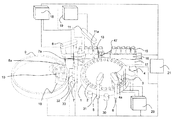
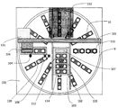
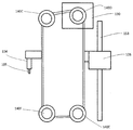
- FIG. 1 is a perspective view of the automatic analyzer of this embodiment.
- an automatic analyzer is a device for dispensing a sample and a reagent in a plurality of reaction vessels 2 and reacting them, and measuring the reacted liquid.
- Reaction container 2 is arranged on the circumference of reaction disk 1.
- a sample transport mechanism 17 for moving a rack 16 on which a sample container 15 is placed is installed near the reaction disk 1.
- a sample dispensing mechanism 11 that can rotate and move up and down is installed, and includes a sample probe 11a.
- a sample syringe 19 is connected to the sample probe 11a. The sample probe 11a moves while drawing an arc around the rotation axis, and dispenses the sample from the sample container 15 to the reaction container 2.
- reagent disk 9 a plurality of reagent bottles 10 can be placed on the circumference.
- the reagent disk 9 is kept cold and is covered with a cover provided with a suction port 111 (see FIG. 2).
- reagent dispensing mechanisms 7 and 8 that can be rotated and moved up and down are installed, and reagent probes 7a and 8a are provided, respectively.
- a reagent syringe 18 is connected to the reagent probes 7a and 8a.
- the reagent probes 7 a and 8 a move while drawing an arc around the rotation axis, access the reagent disk 9 from the suction port 111, and dispense the reagent from the reagent bottle 10 to the reaction container 2.
- a cleaning mechanism 3, a light source 4a, a spectrophotometer 4, and stirring mechanisms 5 and 6 are further arranged.
- a cleaning pump 20 is connected to the cleaning mechanism 3.
- Washing tanks 13, 30, 31, 32, and 33 are installed on the operation ranges of the reagent dispensing mechanisms 7 and 8, the sample dispensing mechanism 11, and the stirring mechanisms 5 and 6, respectively.
- the sample container 15 contains a test sample (specimen) such as blood, and is placed on the rack 16 and carried by the sample transport mechanism 17. Each mechanism is connected to the controller 21.
- the controller 21 is composed of a computer or the like, and controls the operation of each mechanism in the automatic analyzer and performs arithmetic processing for obtaining the concentration of a predetermined component in a liquid sample such as blood or urine.
- the inspection sample analysis processing by the automatic analyzer as described above is generally executed in the following order.
- the sample in the sample container 15 placed on the rack 16 transported near the reaction disk 1 by the sample transport mechanism 17 is transferred to the reaction container 2 on the reaction disk 1 by the sample probe 11 a of the sample dispensing mechanism 11.
- the reagent used for the analysis is dispensed from the reagent bottle 10 on the reagent disk 9 to the reaction container 2 into which the sample has been dispensed by the reagent dispensing mechanisms 7 and 8.
- the mixed solution of the sample and the reagent in the reaction vessel 2 is stirred by the stirring mechanism 5.
- the light generated from the light source 4 a is transmitted through the reaction vessel 2 containing the mixed solution, and the luminous intensity of the transmitted light is measured by the spectrophotometer 4.
- the luminous intensity measured by the spectrophotometer 4 is transmitted to the controller 21 via the A / D converter and the interface. Then, calculation is performed by the controller 21, the concentration of a predetermined component in a liquid sample such as blood or urine is obtained, and the result is displayed on a display unit (not shown) or the like.
- the lid 112 is attached to the reagent probe suction port position of the reagent bottle 10 to seal the inside, and the lid 112 can be removed and installed in the apparatus when set in the automatic analyzer. It is common. However, in recent years, there is a method in which a hole in the notch is formed in the lid 112, and the reagent probes 7a and 8a are inserted into the notch and the reagent in the reagent bottle 10 is sucked. Since the opening of the lid 112 is slightly cut in the reagent, the reagent has minimal contact with the outside air, and the deterioration of the reagent is improved as compared with the conventional case.
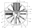
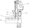
- the autoloader mechanism 100 is arranged on the reagent disk 9 and has a configuration as shown in FIG.
- an autoloader mechanism 100 includes a reagent mounting unit 103, a reagent mounting mechanism 102, a reagent transporting mechanism (reagent transporting unit) 101, a needle cleaning tank 108, a needle drying port 109, a reagent disk opening / closing cover 113, and a bottle direction detection sensor. 114 and an RFID sensor 115.
- the reagent mounting unit 103 is a part for installing the reagent bottle 10 when the reagent bottle 10 is put into the automatic analyzer. Moved up and down.
- the reagent mounting unit 103 has a structure in which a plurality of reagent bottles 10 can be installed on a straight line, and is, for example, a tray having a plurality of reagent bottle slots 107 for installing the reagent bottles 10.
- the reagent buffer 110 is a standby unit for temporarily holding the reagent bottle 10 installed in the reagent mounting unit 103 before being loaded into the reagent disk 9.
- the reagent loading mechanism 102 allows the reagent loading unit 103 to move on the rail along the guide installed between the loading position of the reagent bottle 10 into the apparatus and the reagent buffer 110 by the power of a motor or the like. It is configured.
- the reagent transport mechanism 101 is a mechanism for transporting the reagent bottle 10 installed in the reagent mounting unit 103 into the reagent disk 9, and includes a gripper mechanism (gripper unit) 106 that grips the reagent bottle 10, and a lid of the reagent bottle 10.
- Reagent bottle lid opening mechanism (reagent bottle lid opening portion) 104 that opens a hole in 112
- gripper mechanism and reagent bottle lid opening mechanism driving portion gripper portion and reagent bottle lid opening portion driving portion
- gripper mechanism A horizontal drive motor 131 that drives the 106 and the reagent bottle lid opening mechanism 104 in the left-right direction in FIG.
- the reagent transport mechanism 101 operates in the horizontal direction in FIG. 2 between the position of the reagent loading unit 103 in FIG. 2 and the position of the reagent disk opening (reagent disk opening / closing cover 113). That is, the reagent loading unit 103 moves up and down in FIG. 2, and the reagent transport mechanism 101 operates in the horizontal direction in FIG. 2, so that the operation directions are orthogonal to each other.
- a position where the gripper mechanism 106 grips the reagent bottle 10 and a position where the reagent bottle 10 is carried into and out of the reagent disk 9 are linearly arranged.
- the reagent bottle lid opening mechanism 104 is provided with a needle 105 (see FIG. 4) for incising the reagent bottle lid 112.
- the needle 105 after being cut into the lid 112 is washed in the needle washing tank 108 arranged in parallel to the operation direction of the reagent transport mechanism 101.
- the cleaning water is removed by the needle drying port 109 arranged in parallel with the operation direction of the reagent transport mechanism 101, and the reagent bottle lid 112 is cut so that the reagent is not diluted with the cleaning water.
- the needle cleaning tank 108 and the needle drying port 109 are arranged in parallel to the operation direction of the reagent transport mechanism 101.
- the gripper mechanism 106 has a hooking claw for holding the reagent bottle 10, and holds the reagent bottle 10 by hooking the hooking claw on the notch portion of the reagent bottle 10.
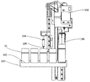
- the gripper mechanism and reagent bottle lid opening mechanism driving unit 120 includes one vertical drive motor 130, a belt A 141 coupled to the vertical drive motor 130, and a vertical drive via the belt A 141.
- a pulley C147 having a pulley A145 that rotates in conjunction with the motor 130, a first pulley portion 147a and a second pulley portion 147b that rotate in conjunction with the pulley A145, and a first pulley of the pulley C147
- Belt B142 connected to the portion 147a and the reagent bottle lid opening mechanism 104, the belt C143 connected to the second pulley portion 147b of the pulley C147 and the gripper mechanism 106, and the reagent bottle lid opening mechanism 104 are guided in the vertical direction. Guide the linear guide A151 and the gripper mechanism 106 in the vertical direction. And a linear guide B152 to.
- the gripper mechanism and reagent bottle lid opening mechanism driving unit 120 are configured such that the gripper mechanism 106 and the reagent bottle lid opening mechanism 104 can be operated in the upside down direction by driving one vertical drive motor 130. Yes.
- the pulley A145 rotates through the belt A141.
- the pulley A145 has a configuration in which a pulley C147 is attached on the same axis, and the pulley C147 rotates in synchronization with the rotation of the pulley A145.
- the first pulley portion 147a to which the belt B142 is attached and the second pulley portion 147b to which the belt C143 is attached are integrated, and the diameter of the first pulley portion 147a and the diameter of the second pulley portion 147b are integrated. It has a different structure. As shown in FIG. 4, when the gripper mechanism 106 grips the reagent bottle 10, the reagent bottle lid opening mechanism 104 is positioned above the gripper mechanism 106, and the reagent bottle lid opening mechanism 104 opens the lid of the reagent bottle 10. The reagent bottle lid opening mechanism 104 is attached to the belt B 142 and the gripper mechanism 106 is attached to the belt C 143 so that the gripper mechanism 106 is positioned above the reagent bottle lid opening mechanism 104 when opening.
- the pulley E149 rotates via the belt B142 by the rotation of the first pulley portion 147a of the pulley C147, and the reagent bottle lid opening mechanism 104 attached to the belt B142 moves in the vertical direction.
- the pulley B146 rotates via the belt C143 by the rotation of the second pulley portion 147b of the pulley C147, and the gripper mechanism 106 attached to the belt C moves in the vertical direction opposite to the reagent bottle lid opening mechanism 104. .
- linear guide A151 and the linear guide B152 are arranged in parallel, and the reagent bottle 10 arranged on the reagent mounting unit 103 can be accessed in the left-right direction in FIG. 4 by separating the distance from each other.
- the reagent bottle lid opening mechanism 104 is arranged so as not to contact the lid of the reagent bottle 10 when the gripper mechanism 106 grips the reagent bottle 10, the interval between the linear guide A151 and the linear guide B152 is reduced.
- the reagent bottles 10 arranged in the reagent mounting unit 103 can be operated side by side.
- the reagent bottle lid opening mechanism 104 and the gripper mechanism 106 move up and down by changing the diameter of the pulley. The amount is changing.
- the diameters of the first pulley portion 147a and the second pulley portion 147b are different from the viewpoint of changing the moving amount of each mechanism.
- the diameter of the second pulley portion 147b is larger than the diameter of the first pulley portion 147a.
- the vertical movement amount of the gripper mechanism 106 is larger than the vertical movement amount of the reagent bottle lid opening mechanism 104 with respect to the rotational operation of the vertical drive motor 130.
- the gripper mechanism 106 is lowered more significantly than the lowering of the reagent bottle lid opening mechanism 104 for carrying the reagent bottle 10 into the reagent disk 9 or the like.
- the bottle direction detection sensor 114 and the RFID sensor 115 are arranged on the operation of the reagent loading mechanism 102.
- the bottle direction detection sensor 114 measures the presence / absence and installation direction of the reagent bottle of the reagent bottle 10.
- the RFID sensor 115 obtains information on the reagent in the reagent bottle 10 recorded on the RFID tag 10 a provided in the reagent bottle 10.
- the reagent disk opening / closing cover 113 is a cover for preventing the cool air inside the kept reagent disk 9 from escaping, and is normally closed.
- the reagent disk opening / closing cover 113 is opened and operates so that the reagent bottle 10 can be loaded into and unloaded from the reagent disk 9.
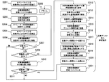
- a reagent button switch (not shown) of the apparatus is first pressed.
- the apparatus recognizes that the first press of the reagent button switch has been performed by the operator (step S201).
- the reagent loading mechanism 102 operates, the reagent loading unit 103 is unloaded from the reagent buffer 110 (step S202), and moves to the front of the apparatus (lower part in FIG. 6) as shown in FIG. 6 (step S203).
- the autoloader mechanism 100 has a structure in which the inside of the apparatus cannot be accessed by a normal interlock.
- the reagent mounting part 103 is placed on the front of the apparatus.
- the interlock mechanism of the reagent loading unit cover 116 is released, the reagent loading unit cover 116 shown in FIG. 7 is opened, and the operator installs the reagent bottle 10 in the empty reagent bottle slot 107 of the reagent loading unit 103. ing.
- the reagent mounting part cover 116 is opened, as shown in FIG.
- the rear side of the reagent mounting portion 103 is installed with a high wall 103a so that the interior of the autoloader mechanism 100 cannot be accessed even when there is no reagent bottle.
- the height of the wall 103a is preferably equal to the height at which the reagent bottle 10 is installed or higher than the height at which the reagent bottle 10 is installed.
- the gap increases so that the operator can access the inside of the autoloader mechanism 100 more. This is to reduce.
- the operator can perform reagent replacement work even while the apparatus is analyzing.
- step S204 After installing the necessary number of reagent bottles 10 in the reagent mounting unit 103, the operator closes the reagent mounting unit cover 116 and presses the reagent button switch again.
- the apparatus recognizes that the operator has pressed the reagent button switch for the second time (step S205).
- the reagent mounting portion 103 has five reagent bottle slots 107 for installing the reagent bottles 10, the operator has installed the reagent bottles in the front and back, and there are three places in the front and back. The operation in the case of installation will be described.
- the reagent bottle installed on the back side in FIG. 3 is referred to as a reagent bottle 10A, and the front side is referred to as a reagent bottle 10B.
- the reagent loading unit 103 moves and passes under the bottle direction detection sensor 114 (step S206). At this time, it is determined whether the reagent bottle 10 is installed by measuring the orientation of the reagent bottle 10 and the presence / absence of the reagent bottle from the reagent bottle 10A to the reagent bottle 10B sequentially by the bottle orientation detection sensor 114. Is performed (step S207). When it is determined that it is installed, the process proceeds to step S208, and when it is determined that it is not installed, the process proceeds to step S221.
- the installation orientation of the reagent bottle 10 is determined (step S208).
- the process proceeds to step S210, and when it is determined that it is not correctly installed (NG), the process proceeds to step S209.
- the determination of the installation direction of the reagent bottle 10 includes, for example, a method in which a black and white label is attached to the reagent bottle 10 and the determination of the white and black directions is performed by a sensor.
- the presence / absence of the reagent bottle 10 can also be determined by determining whether or not light is shielded by arranging a reflective sensor or beam sensor.
- step S208 When it is determined in step S208 that the installation direction of the reagent bottle 10 is reverse, an alarm is issued and the reagent loading unit 103 moves to the front of the apparatus, and the interlock of the reagent loading unit cover 116 is released to prompt the operator. Attention is notified (step S209). It is also assumed that the operator is not aware of the alarm even though the operator has been alerted by the alarm. Therefore, it is desirable to return the reagent mounting unit 103 to the reagent buffer 110 while maintaining an alarm after a certain period of time has elapsed. In addition, a correction mechanism that automatically corrects the installation direction of the reagent bottle 10 may be provided so that the correction is automatically performed.
- the reagent mounting unit 103 moves to the RFID detection unit, reads information on the RFID tag 10a of the reagent bottle 10 with the RFID sensor 115, and obtains information on the reagent in the reagent bottle 10 (step S210).
- the configuration in which the detection of the bottle direction detection sensor 114 and the measurement of the RFID sensor 115 are performed at the same time can be performed by matching the installation interval of the bottle direction detection sensor 114 and the RFID sensor 115 with the reagent bottle installation distance of the reagent mounting unit 103. It is also possible to detect the direction of the bottle and the presence / absence of the installation first, and measure the installed location with the RFID sensor 115. Further, the bottle direction detection sensor 114 and the RFID sensor 115 may be arranged at the same position, and the direction and information of the reagent bottle 10 installed in the reagent mounting unit 103 may be simultaneously performed or measurement may be sequentially performed.
- step S211 it is determined whether or not it is necessary to carry in the reagent disk 9 of the reagent bottle 10 (step S211).
- step S212 it is determined that the reagent bottle 10 needs to be carried in.
- step S221 it is determined that the reagent bottle 10 is not necessary.
- step S211 If it is determined in step S211 that the reagent bottle 10 needs to be carried into the reagent disk 9, the reagent mounting unit 103 moves to a position below the reagent bottle lid opening mechanism 104 as shown in FIG. S212).
- the reagent bottle lid opening mechanism 104 is lowered toward the reagent bottle lid 112 of the reagent bottle 10, and the needle 105 is used to open a notch that allows the reagent probes 7a and 8a to be inserted into the bottle lid 112 (step S213).
- the reagent bottle lid opening mechanism 104 moves up, and the reagent transport mechanism 101 moves to the position of the needle washing tank 108 to wash the needle 105, and the needle 105 is washed. Thereafter, the needle moves to the needle drying port 109 and the needle 105 is dried. Thereafter, the second reagent bottle lid 112 is similarly cut, and the needle 105 is washed and dried (step S214).
- the number of reagent bottle lids 112 is two, but the same applies when there are a plurality of reagent bottle lids 112.
- the reagent loading mechanism 102 again moves the reagent loading portion 103 to a position below the gripper mechanism 106 (step S215). Specifically, as shown in FIG. 9, the reagent mounting mechanism 102 operates the reagent mounting unit 103 to move the cut reagent bottle 10 to a position below the gripper mechanism 106.
- the gripper mechanism 106 is lowered to grasp the reagent bottle 10 (step S216), and then the reagent disk opening / closing cover 113 is opened (step S217). Thereafter, the gripper mechanism 106 is raised and moved to the position of the opened reagent disk opening / closing cover 113, and the reagent bottle 10 transported to the position of the empty reagent disk 9 is carried in as shown in FIG. 10 (step S218). After carrying in, the gripper mechanism 106 is again returned to the position of the reagent mounting unit 103 (step S219).
- the reagent bottle 10 When the reagent bottle 10 is carried into the reagent disk 9 while the apparatus is measuring, means for delaying the sample suction timing by one cycle is provided so that the reagent transport mechanism 101 can access the reagent disk 9. It is desirable to provide an empty cycle. As a result, the reagent bottle 10 can be replaced while maintaining the processing speed with only a time loss corresponding to the empty cycle.
- steps S215 to S219 described above are repeated for all the reagent bottles 10 that are mounted on the reagent mounting unit 103 and need to be carried into the reagent disk 9.
- the reagent disk opening / closing cover 113 is closed (step S220).
- the reagent mounting unit 103 is returned to the reagent buffer 110 together with the installed reagent bottle 10 to the reagent buffer 110.
- the reagent bottle 10 is put on standby (step S221).
- the reagent bottle 10 held in the reagent buffer 110 is cut into the reagent bottle lid 112 by the reagent bottle lid opening mechanism 104 as necessary, and then carried into the reagent disk 9 by the gripper mechanism 106.
- step S212 to step S221 corresponds to the reagent disk insertion preliminary operation.
- the reagent disk 10 One or several empty reagent bottle slots are provided for the nine installable numbers. Then, the reagent bottle 10 installed in the reagent loading unit 103 is loaded into the reagent disk 9 without cutting into the reagent bottle lid 112, and the empty reagent bottle 10 is gripped by the gripper mechanism 106, and the reagent loading unit After being placed on 103, the operator carries out the empty reagent bottle 10. After unloading, the reagent bottle 10 that is not cut in the reagent disk 9 can be returned to the empty reagent bottle slot 107 again. A similar operation can be performed if an empty slot is provided in the reagent mounting unit 103.
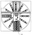
- FIG. 11 is a diagram showing a home position.
- the reagent bottle lid opening mechanism 104 and the gripper mechanism 106 are not in contact with the reagent bottle 10 in a positional relationship. That is, at the home position, the reagent mounting unit 103 can move back and forth.
- the operation of cutting the reagent bottle lid 112 and the operation of loading and unloading the reagent bottle 10 are the shortest moving distance. Can be done. Further, the operation before and after the reagent loading unit 103 can be operated without interfering with the reagent bottle lid opening mechanism 104 and the gripper mechanism 106, and an arbitrary position of the reagent bottle 10 installed in the reagent loading unit 103 can be accessed. is there.
- the interval between the reagent bottle lid opening mechanism 104 and the gripper mechanism 106 is one interval of the reagent bottle 10, but the interval between the reagent bottle lid opening mechanism 104 and the gripper mechanism 106 is a component. Therefore, the interval between the reagent bottle lid opening mechanism 104 and the gripper mechanism 106 with respect to the interval between the reagent bottles 10 may or may not be opened.
- FIG. 12 is a view showing a state in which the reagent bottle lid opening mechanism 104 is lowered in order to make a cut in the reagent bottle lid 112 of the reagent bottle 10.
- the gripper mechanism 106 operates in conjunction with the home position.
- the reagent transport mechanism 101 moves to the needle cleaning tank 108 and the needle drying port 109 to clean and dry the needle 105.
- the reagent bottle lid opening mechanism 104 is The needle 105 is efficiently cleaned and dried by moving up and down.
- FIG. 13 is a view showing a state where the gripper mechanism 106 is lowered to hold the reagent bottle 10.
- the gripper mechanism 106 since the gripper mechanism 106 is lowered, the reagent bottle lid opening mechanism 104 is moved upward from the home position in conjunction with it.
- FIG. 14 is a diagram showing a state in which the reagent bottle 10 is lifted by the gripper mechanism 106.
- the reagent mounting unit 103 has a structure in which a notch 160 is inserted so that the reagent bottle 10 can move from the reagent mounting unit 103 with a minimum lifting amount.
- the reagent bottle lid opening mechanism 104 moves downward from the time of FIG. 13, but the needle 105 of the reagent bottle lid opening mechanism 104 has a vertical positional relationship so as not to contact the reagent bottle 10. It has been.
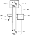
- the gripper mechanism 106 on the right side of the belt in FIG. 15 and the reagent bottle lid opening mechanism 104 on the left side can be configured.
- the positions of the reagent bottle lid opening mechanism 104 and the gripper mechanism 106 are set at necessary distances by changing the diameters of the pulleys 140A and 140B, or offset by the pulleys 140C, 140D, 140E, and 140F as shown in FIG.
- the interval between the reagent bottle lid opening mechanism 104 and the gripper mechanism 106 can be set to a desired interval, or the amount of vertical movement between the reagent bottle lid opening mechanism 104 and the gripper mechanism 106 can be changed. it can.
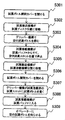
- the reagent bottle 10 is carried out according to the flow of FIG. 17 according to the flow of FIG. 17 .
- the carry-out timing of the reagent bottle 10 as shown in FIG. 17 may be performed even after the analysis, after the end of the last dispensing of the reagent dispensing mechanism 8 or after the output of the analysis result.
- the reagent transport mechanism 101 opens the reagent disk opening / closing cover 113 (step S301).
- the reagent transport mechanism 101 moves to the position of the opened reagent disk opening / closing cover 113 (step S302).
- step S303 the empty reagent bottle 10 is gripped by the gripper mechanism 106 (step S303).
- the reagent mounting mechanism 102 moves out of the reagent buffer 110 and stops above the position of the empty reagent bottle slot 107 of the reagent mounting unit 103 (step S304).
- the reagent transport mechanism 101 moves to the position of the reagent loading mechanism 102 while holding the empty reagent bottle 10 by the gripper mechanism 106 (step S305).
- the reagent disk opening / closing cover 113 is closed (step S306).
- the empty reagent bottle 10 is placed in the empty reagent bottle slot 107 of the reagent mounting unit 103 by the gripper mechanism 106 (step S307). Thereafter, the reagent loading mechanism 102 returns to the reagent buffer 110 (step S308).
- step S309 the operator is notified that the empty reagent bottle 10 can be taken out. Upon receiving this notification, the operator takes out the empty reagent bottle 10 from the apparatus.
- the gripper mechanism 106, the reagent disk loading position, and the reagent nozzle suction port 111 are arranged in a straight line, but the reagent nozzle suction port is within a range in which the reagent probes 7a and 8a can operate. I'm not bound by this.
- the needle 105 is described as one, but when there are two reagent lid positions as in the reagent bottle 10, two needles 105 are attached at intervals of the reagent lid hole.
- the reagent bottle lid opening mechanism 104 is lowered to simultaneously open holes in two lids.
- two needle cleaning tanks 108 and needle drying ports 109 are installed at intervals of the needle 105.
- the operations of the gripper mechanism 106 and the reagent bottle lid opening mechanism 104 are described as the vertical movement by the vertical drive motor 130 and the horizontal movement by the horizontal drive motor 131. If the operation in three directions is possible, it is possible to increase the number of reagent bottles 10 that can be placed on the reagent mounting unit 103.
- the gripper mechanism 106 that grips the reagent bottle 10 and the reagent bottle lid opening mechanism 104 that cuts into the lid of the reagent bottle 10 are combined into one actuator (the gripper mechanism and the reagent bottle).
- the gripper mechanism 106 is driven to move downward in order to cut into the reagent bottle lid 112
- the gripper mechanism 106 is raised
- the gripper mechanism 106 moves downward to grip the reagent bottle 10
- the reagent bottle lid opening mechanism 104 is lifted, and operates without interfering with each other's functions.
- the reagent bottle lid opening mechanism 104 and the gripper mechanism 106 are driven in the opposite directions by one actuator, so that the reagent bottle lid opening mechanism 104 and the gripper mechanism 106 need to be configured as separate mechanisms. Disappears. As a result, the number of parts can be reduced. Furthermore, adjustment and maintenance can be improved, and the installation space of the apparatus can be minimized.
- the risk of cutting the unnecessary lid 112 of the reagent bottle 10 can be reduced.
- the operation can be performed without interference by reducing the input amount of the reagent bottle 10, but the input amount of the reagent bottle 10 is reduced, and the operation and time for the operator to fill the reagent.
- Reagent dispensing mechanism cleaning tank 100 Autoloader mechanism 101 ... Reagent transport mechanism (reagent transport section) (moving in the X direction) 102 ... Reagent mounting mechanism (tray mechanism) 103 ... Reagent mounting part (tray) 104 ... Reagent bottle lid opening mechanism (reagent bottle lid opening part) 105 ... Needle (Pierce) 106 ... Gripper mechanism (gripper part) 107: Reagent bottle slot (reagent bottle can be installed) DESCRIPTION OF SYMBOLS 108 ... Needle washing tank 109 ... Needle drying port 110 ... Reagent buffer 111 ... Reagent nozzle suction port 112 ... Reagent bottle lid 113 ...
Landscapes
- Chemical & Material Sciences (AREA)
- General Health & Medical Sciences (AREA)
- Life Sciences & Earth Sciences (AREA)
- Health & Medical Sciences (AREA)
- Analytical Chemistry (AREA)
- Biochemistry (AREA)
- Physics & Mathematics (AREA)
- General Physics & Mathematics (AREA)
- Immunology (AREA)
- Pathology (AREA)
- Engineering & Computer Science (AREA)
- Robotics (AREA)
- Chemical Kinetics & Catalysis (AREA)
- Automatic Analysis And Handling Materials Therefor (AREA)
Abstract
Priority Applications (4)
| Application Number | Priority Date | Filing Date | Title |
|---|---|---|---|
| EP16761450.2A EP3270168B1 (fr) | 2015-03-10 | 2016-02-18 | Dispositif d'analyse automatisé |
| CN201680013135.9A CN107407689B (zh) | 2015-03-10 | 2016-02-18 | 自动分析装置 |
| US15/556,081 US10613108B2 (en) | 2015-03-10 | 2016-02-18 | Automatic analyzer |
| JP2017504942A JP6602367B2 (ja) | 2015-03-10 | 2016-02-18 | 自動分析装置 |
Applications Claiming Priority (2)
| Application Number | Priority Date | Filing Date | Title |
|---|---|---|---|
| JP2015047286 | 2015-03-10 | ||
| JP2015-047286 | 2015-03-10 |
Publications (1)
| Publication Number | Publication Date |
|---|---|
| WO2016143478A1 true WO2016143478A1 (fr) | 2016-09-15 |
Family
ID=56879569
Family Applications (1)
| Application Number | Title | Priority Date | Filing Date |
|---|---|---|---|
| PCT/JP2016/054764 WO2016143478A1 (fr) | 2015-03-10 | 2016-02-18 | Dispositif d'analyse automatisé |
Country Status (5)
| Country | Link |
|---|---|
| US (1) | US10613108B2 (fr) |
| EP (1) | EP3270168B1 (fr) |
| JP (1) | JP6602367B2 (fr) |
| CN (1) | CN107407689B (fr) |
| WO (1) | WO2016143478A1 (fr) |
Cited By (5)
| Publication number | Priority date | Publication date | Assignee | Title |
|---|---|---|---|---|
| JP2018048901A (ja) * | 2016-09-21 | 2018-03-29 | 株式会社日立ハイテクノロジーズ | 自動分析装置 |
| JP2018136225A (ja) * | 2017-02-22 | 2018-08-30 | 株式会社日立ハイテクノロジーズ | 自動分析装置 |
| KR20190020412A (ko) * | 2017-08-21 | 2019-03-04 | 한국산업기술시험원 | 수질연속측정기용 자동시료채취장치 |
| KR20190040709A (ko) * | 2017-10-11 | 2019-04-19 | 주식회사 포스코 | 수질 분석용 장치 |
| JP7453972B2 (ja) | 2018-11-13 | 2024-03-21 | グレート ノース リサーチ アンド イノベーション リミテッド | 装置 |
Families Citing this family (7)
| Publication number | Priority date | Publication date | Assignee | Title |
|---|---|---|---|---|
| JP6419540B2 (ja) * | 2014-11-14 | 2018-11-07 | シスメックス株式会社 | 検体測定装置および検体測定方法 |
| CN113490853B (zh) * | 2019-03-01 | 2023-10-03 | 株式会社日立高新技术 | 自动分析装置 |
| JP7245106B2 (ja) * | 2019-04-11 | 2023-03-23 | 株式会社日立ハイテク | インターロックユニットおよびそれを備えた自動分析装置 |
| CN210347441U (zh) * | 2019-06-13 | 2020-04-17 | 株式会社岛津制作所 | 自动进样器 |
| CN110514860A (zh) * | 2019-08-22 | 2019-11-29 | 长沙力源健康发展有限公司 | 急诊血液检测样品自动进样装置 |
| WO2023073667A1 (fr) * | 2021-11-01 | 2023-05-04 | Beckman Coulter, Inc. | Système de chargement/déchargement de récipients de produits consommables et procédé de chargement/déchargement de récipients de produits consommables pour automate d'analyse |
| CN115615754B (zh) * | 2022-09-05 | 2023-09-19 | 苏州大学附属儿童医院 | 一种采样管用自动取样机 |
Citations (5)
| Publication number | Priority date | Publication date | Assignee | Title |
|---|---|---|---|---|
| JP2004264044A (ja) * | 2003-01-31 | 2004-09-24 | Universal Bio Research Co Ltd | 監視機能付分注装置および分注装置の監視方法 |
| JP2008203004A (ja) * | 2007-02-19 | 2008-09-04 | Hitachi High-Technologies Corp | 自動分析装置 |
| JP2010175420A (ja) * | 2009-01-30 | 2010-08-12 | Hitachi High-Technologies Corp | 試料分析装置 |
| JP2012117916A (ja) * | 2010-12-01 | 2012-06-21 | Hitachi High-Technologies Corp | 自動分析装置 |
| JP2013500489A (ja) * | 2009-07-29 | 2013-01-07 | エフ.ホフマン−ラ ロシュ アーゲー | 自動分析器 |
Family Cites Families (3)
| Publication number | Priority date | Publication date | Assignee | Title |
|---|---|---|---|---|
| US5314825A (en) * | 1992-07-16 | 1994-05-24 | Schiapparelli Biosystems, Inc. | Chemical analyzer |
| JP4033060B2 (ja) | 2003-07-17 | 2008-01-16 | 株式会社日立ハイテクノロジーズ | 自動分析装置 |
| US9678093B2 (en) * | 2013-08-20 | 2017-06-13 | Hitachi High-Technologies Corporation | Automatic analyzer |
-
2016
- 2016-02-18 WO PCT/JP2016/054764 patent/WO2016143478A1/fr active Application Filing
- 2016-02-18 EP EP16761450.2A patent/EP3270168B1/fr active Active
- 2016-02-18 CN CN201680013135.9A patent/CN107407689B/zh active Active
- 2016-02-18 US US15/556,081 patent/US10613108B2/en active Active
- 2016-02-18 JP JP2017504942A patent/JP6602367B2/ja active Active
Patent Citations (5)
| Publication number | Priority date | Publication date | Assignee | Title |
|---|---|---|---|---|
| JP2004264044A (ja) * | 2003-01-31 | 2004-09-24 | Universal Bio Research Co Ltd | 監視機能付分注装置および分注装置の監視方法 |
| JP2008203004A (ja) * | 2007-02-19 | 2008-09-04 | Hitachi High-Technologies Corp | 自動分析装置 |
| JP2010175420A (ja) * | 2009-01-30 | 2010-08-12 | Hitachi High-Technologies Corp | 試料分析装置 |
| JP2013500489A (ja) * | 2009-07-29 | 2013-01-07 | エフ.ホフマン−ラ ロシュ アーゲー | 自動分析器 |
| JP2012117916A (ja) * | 2010-12-01 | 2012-06-21 | Hitachi High-Technologies Corp | 自動分析装置 |
Non-Patent Citations (1)
| Title |
|---|
| See also references of EP3270168A4 * |
Cited By (7)
| Publication number | Priority date | Publication date | Assignee | Title |
|---|---|---|---|---|
| JP2018048901A (ja) * | 2016-09-21 | 2018-03-29 | 株式会社日立ハイテクノロジーズ | 自動分析装置 |
| JP2018136225A (ja) * | 2017-02-22 | 2018-08-30 | 株式会社日立ハイテクノロジーズ | 自動分析装置 |
| KR20190020412A (ko) * | 2017-08-21 | 2019-03-04 | 한국산업기술시험원 | 수질연속측정기용 자동시료채취장치 |
| KR101992612B1 (ko) * | 2017-08-21 | 2019-06-25 | 한국산업기술시험원 | 수질연속측정기용 자동시료채취장치 |
| KR20190040709A (ko) * | 2017-10-11 | 2019-04-19 | 주식회사 포스코 | 수질 분석용 장치 |
| KR102027901B1 (ko) | 2017-10-11 | 2019-10-04 | 주식회사 포스코 | 수질 분석용 장치 |
| JP7453972B2 (ja) | 2018-11-13 | 2024-03-21 | グレート ノース リサーチ アンド イノベーション リミテッド | 装置 |
Also Published As
| Publication number | Publication date |
|---|---|
| CN107407689B (zh) | 2020-05-26 |
| EP3270168A1 (fr) | 2018-01-17 |
| CN107407689A (zh) | 2017-11-28 |
| US20180267068A1 (en) | 2018-09-20 |
| JP6602367B2 (ja) | 2019-11-06 |
| US10613108B2 (en) | 2020-04-07 |
| EP3270168A4 (fr) | 2018-11-07 |
| EP3270168B1 (fr) | 2020-04-08 |
| JPWO2016143478A1 (ja) | 2017-12-28 |
Similar Documents
| Publication | Publication Date | Title |
|---|---|---|
| JP6602367B2 (ja) | 自動分析装置 | |
| JP5178830B2 (ja) | 自動分析装置 | |
| JP6655087B2 (ja) | 自動分析装置および試薬ボトルの搬入方法 | |
| JP2008020361A (ja) | 自動分析装置 | |
| JP7189339B2 (ja) | 自動分析装置 | |
| WO2017141696A1 (fr) | Dispositif d'analyse automatisé | |
| JP6886837B2 (ja) | 自動分析装置 | |
| JP5258615B2 (ja) | 自動分析装置 | |
| JP5485014B2 (ja) | 自動分析装置 | |
| JP6509218B2 (ja) | 自動分析装置 | |
| JP2005164506A (ja) | 自動分析装置 | |
| JP7054616B2 (ja) | 自動分析装置 | |
| JP2012063179A (ja) | 自動分析装置 | |
| JP7433459B2 (ja) | 自動分析装置 | |
| JP7179928B2 (ja) | 自動分析装置 | |
| JP2015175783A (ja) | 自動分析装置 | |
| WO2023008069A1 (fr) | Dispositif d'analyse automatique et procédé de guidage utilisé dans un dispositif d'analyse automatique | |
| WO2022176556A1 (fr) | Dispositif d'analyse automatique et procédé d'aspiration d'échantillon dans un dispositif d'analyse automatique | |
| JP2023033053A (ja) | 自動分析装置 | |
| JP2023068295A (ja) | 洗剤ボトル及び自動分析装置 | |
| JP5321324B2 (ja) | 反応容器の供給手段を切り替え可能な自動分析装置 | |
| JP2018044847A (ja) | 自動分析装置 | |
| JP2008233004A (ja) | 分析装置 |
Legal Events
| Date | Code | Title | Description |
|---|---|---|---|
| 121 | Ep: the epo has been informed by wipo that ep was designated in this application |
Ref document number: 16761450 Country of ref document: EP Kind code of ref document: A1 |
|
| ENP | Entry into the national phase |
Ref document number: 2017504942 Country of ref document: JP Kind code of ref document: A |
|
| REEP | Request for entry into the european phase |
Ref document number: 2016761450 Country of ref document: EP |
|
| WWE | Wipo information: entry into national phase |
Ref document number: 15556081 Country of ref document: US |
|
| NENP | Non-entry into the national phase |
Ref country code: DE |