WO2016143472A1 - 軸受用保持器および軸受 - Google Patents
軸受用保持器および軸受 Download PDFInfo
- Publication number
- WO2016143472A1 WO2016143472A1 PCT/JP2016/054513 JP2016054513W WO2016143472A1 WO 2016143472 A1 WO2016143472 A1 WO 2016143472A1 JP 2016054513 W JP2016054513 W JP 2016054513W WO 2016143472 A1 WO2016143472 A1 WO 2016143472A1
- Authority
- WO
- WIPO (PCT)
- Prior art keywords
- cage
- bearing
- thickness
- ball
- Prior art date
Links
Images


Classifications
-
- F—MECHANICAL ENGINEERING; LIGHTING; HEATING; WEAPONS; BLASTING
- F16—ENGINEERING ELEMENTS AND UNITS; GENERAL MEASURES FOR PRODUCING AND MAINTAINING EFFECTIVE FUNCTIONING OF MACHINES OR INSTALLATIONS; THERMAL INSULATION IN GENERAL
- F16C—SHAFTS; FLEXIBLE SHAFTS; ELEMENTS OR CRANKSHAFT MECHANISMS; ROTARY BODIES OTHER THAN GEARING ELEMENTS; BEARINGS
- F16C33/00—Parts of bearings; Special methods for making bearings or parts thereof
- F16C33/30—Parts of ball or roller bearings
- F16C33/66—Special parts or details in view of lubrication
- F16C33/6637—Special parts or details in view of lubrication with liquid lubricant
- F16C33/6681—Details of distribution or circulation inside the bearing, e.g. grooves on the cage or passages in the rolling elements
-
- F—MECHANICAL ENGINEERING; LIGHTING; HEATING; WEAPONS; BLASTING
- F16—ENGINEERING ELEMENTS AND UNITS; GENERAL MEASURES FOR PRODUCING AND MAINTAINING EFFECTIVE FUNCTIONING OF MACHINES OR INSTALLATIONS; THERMAL INSULATION IN GENERAL
- F16C—SHAFTS; FLEXIBLE SHAFTS; ELEMENTS OR CRANKSHAFT MECHANISMS; ROTARY BODIES OTHER THAN GEARING ELEMENTS; BEARINGS
- F16C19/00—Bearings with rolling contact, for exclusively rotary movement
- F16C19/02—Bearings with rolling contact, for exclusively rotary movement with bearing balls essentially of the same size in one or more circular rows
- F16C19/04—Bearings with rolling contact, for exclusively rotary movement with bearing balls essentially of the same size in one or more circular rows for radial load mainly
- F16C19/06—Bearings with rolling contact, for exclusively rotary movement with bearing balls essentially of the same size in one or more circular rows for radial load mainly with a single row or balls
-
- F—MECHANICAL ENGINEERING; LIGHTING; HEATING; WEAPONS; BLASTING
- F16—ENGINEERING ELEMENTS AND UNITS; GENERAL MEASURES FOR PRODUCING AND MAINTAINING EFFECTIVE FUNCTIONING OF MACHINES OR INSTALLATIONS; THERMAL INSULATION IN GENERAL
- F16C—SHAFTS; FLEXIBLE SHAFTS; ELEMENTS OR CRANKSHAFT MECHANISMS; ROTARY BODIES OTHER THAN GEARING ELEMENTS; BEARINGS
- F16C33/00—Parts of bearings; Special methods for making bearings or parts thereof
- F16C33/30—Parts of ball or roller bearings
- F16C33/38—Ball cages
- F16C33/3887—Details of individual pockets, e.g. shape or ball retaining means
-
- F—MECHANICAL ENGINEERING; LIGHTING; HEATING; WEAPONS; BLASTING
- F16—ENGINEERING ELEMENTS AND UNITS; GENERAL MEASURES FOR PRODUCING AND MAINTAINING EFFECTIVE FUNCTIONING OF MACHINES OR INSTALLATIONS; THERMAL INSULATION IN GENERAL
- F16C—SHAFTS; FLEXIBLE SHAFTS; ELEMENTS OR CRANKSHAFT MECHANISMS; ROTARY BODIES OTHER THAN GEARING ELEMENTS; BEARINGS
- F16C33/00—Parts of bearings; Special methods for making bearings or parts thereof
- F16C33/30—Parts of ball or roller bearings
- F16C33/38—Ball cages
- F16C33/41—Ball cages comb-shaped
- F16C33/412—Massive or moulded comb cages, e.g. snap ball cages
- F16C33/414—Massive or moulded comb cages, e.g. snap ball cages formed as one-piece cages, i.e. monoblock comb cages
- F16C33/416—Massive or moulded comb cages, e.g. snap ball cages formed as one-piece cages, i.e. monoblock comb cages made from plastic, e.g. injection moulded comb cages
-
- F—MECHANICAL ENGINEERING; LIGHTING; HEATING; WEAPONS; BLASTING
- F16—ENGINEERING ELEMENTS AND UNITS; GENERAL MEASURES FOR PRODUCING AND MAINTAINING EFFECTIVE FUNCTIONING OF MACHINES OR INSTALLATIONS; THERMAL INSULATION IN GENERAL
- F16C—SHAFTS; FLEXIBLE SHAFTS; ELEMENTS OR CRANKSHAFT MECHANISMS; ROTARY BODIES OTHER THAN GEARING ELEMENTS; BEARINGS
- F16C33/00—Parts of bearings; Special methods for making bearings or parts thereof
- F16C33/30—Parts of ball or roller bearings
- F16C33/38—Ball cages
- F16C33/41—Ball cages comb-shaped
- F16C33/418—Details of individual pockets, e.g. shape or ball retaining means
-
- F—MECHANICAL ENGINEERING; LIGHTING; HEATING; WEAPONS; BLASTING
- F16—ENGINEERING ELEMENTS AND UNITS; GENERAL MEASURES FOR PRODUCING AND MAINTAINING EFFECTIVE FUNCTIONING OF MACHINES OR INSTALLATIONS; THERMAL INSULATION IN GENERAL
- F16C—SHAFTS; FLEXIBLE SHAFTS; ELEMENTS OR CRANKSHAFT MECHANISMS; ROTARY BODIES OTHER THAN GEARING ELEMENTS; BEARINGS
- F16C33/00—Parts of bearings; Special methods for making bearings or parts thereof
- F16C33/30—Parts of ball or roller bearings
- F16C33/66—Special parts or details in view of lubrication
- F16C33/6603—Special parts or details in view of lubrication with grease as lubricant
- F16C33/6629—Details of distribution or circulation inside the bearing, e.g. grooves on the cage or passages in the rolling elements
-
- F—MECHANICAL ENGINEERING; LIGHTING; HEATING; WEAPONS; BLASTING
- F16—ENGINEERING ELEMENTS AND UNITS; GENERAL MEASURES FOR PRODUCING AND MAINTAINING EFFECTIVE FUNCTIONING OF MACHINES OR INSTALLATIONS; THERMAL INSULATION IN GENERAL
- F16C—SHAFTS; FLEXIBLE SHAFTS; ELEMENTS OR CRANKSHAFT MECHANISMS; ROTARY BODIES OTHER THAN GEARING ELEMENTS; BEARINGS
- F16C2380/00—Electrical apparatus
- F16C2380/26—Dynamo-electric machines or combinations therewith, e.g. electro-motors and generators
-
- F—MECHANICAL ENGINEERING; LIGHTING; HEATING; WEAPONS; BLASTING
- F16—ENGINEERING ELEMENTS AND UNITS; GENERAL MEASURES FOR PRODUCING AND MAINTAINING EFFECTIVE FUNCTIONING OF MACHINES OR INSTALLATIONS; THERMAL INSULATION IN GENERAL
- F16C—SHAFTS; FLEXIBLE SHAFTS; ELEMENTS OR CRANKSHAFT MECHANISMS; ROTARY BODIES OTHER THAN GEARING ELEMENTS; BEARINGS
- F16C33/00—Parts of bearings; Special methods for making bearings or parts thereof
- F16C33/30—Parts of ball or roller bearings
- F16C33/38—Ball cages
- F16C33/44—Selection of substances
Definitions
- the present invention relates to a bearing cage and a bearing.
- the conventional bearing (ball bearing) is arranged on the outer side of the inner ring 2 having the inner race surface 2a formed on the outer diameter surface and on the outer side of the inner ring 2, and on the inner diameter surface.
- An outer ring 3 having a surface 3a formed thereon, a plurality of balls 4 movably interposed between an inner rolling surface 2a of the inner ring 2 and an outer rolling surface 3a of the outer ring 3, an inner ring 2 and an outer ring 3, And a resin cage 5 that holds the balls 4 at equal intervals in the circumferential direction.
- Either the outer ring 3 or the inner ring 2 is attached to a fixed part such as a housing, and the other is attached to a rotating part such as a rotating shaft.
- the crown-shaped cage 5 disposed between the inner ring 2 and the outer ring 3 includes an annular main portion 5a and axially one side surfaces of the main portion 5a.
- An open pocket 5c is provided, and the ball 4 is held by the pocket 5c so as to roll freely.
- seal members 6 for sealing an annular space between the inner ring 2 and the outer ring 3 are arranged on both sides in the axial direction of the inner ring 2 and the outer ring 3 as shown in FIG.
- the seal member 6 includes a cored bar 6a and an elastic body 6b that is integrally vulcanized and bonded to the cored bar 6a.
- a base end of the seal member 6 is attached to an inner diameter end of the outer ring 3, and a tip of the inner ring 2 is attached.
- a seal lip 6c is formed in contact with the outer diameter end of the.
- the outer ring 3 to which the base end portion of the seal member 6 is mounted is the fixed side
- the inner ring 2 with which the seal lip 6c contacts is the rotating side.
- the inner ring 2 rotates while maintaining the state in which the seal lip 6 c at the tip of the seal member 6 is in sliding contact with the outer diameter end of the inner ring 2. This prevents foreign matters such as water and dust from entering the inside of the bearing or leakage of a lubricant such as grease from the inside of the bearing to the outside.
- Patent Documents 1 to 4 Various proposals have been made to solve the problem by centrifugal force generated during high-speed rotation.
- the cage described in Patent Document 1 includes an annular part and a plurality of cantilevered pillar parts extending from one side surface of the annular part, and is formed by an annular part and a neighboring pillar part.
- a ball is slidably accommodated in each pocket.
- the cage is designed in such a manner that it is inclined inward in the radial direction from the annular portion toward the tip portion of the column portion in advance by a predetermined amount of deformation due to centrifugal force in consideration of radial deformation due to centrifugal force. Sometimes the tilt is corrected when it is deformed by centrifugal force, and the column portion is substantially horizontal in the axial direction so that the contact position between the ball and the pocket of the cage is appropriate.
- the cage described in Patent Document 2 is a combination cage made of synthetic resin when engaging the flange of the second element that is the engaging portion and the step portion of the first element that is the engaged portion.
- the elastic deformation amount of the engaging portion is reduced or eliminated.
- a fixing piece that fills the gap between the protrusions is inserted into the through hole, and both elements are fixed together by the fixing piece, thereby increasing the engaging force of both elements. is there.
- Patent Document 3 as shown in FIG. 1, by providing a concave portion (a lightening portion) in the inner diameter portion of the crown-shaped cage, it is prevented from coming into contact with a portion having a high rotation speed of the ball during high-speed rotation. To do. That is, the interference part between the inner wall surface constituting the pocket of the crown-shaped cage and the ball is reduced.
- Patent Document 4 integrates an auxiliary ring made of an annular metal plate having higher rigidity than a synthetic resin of a crown type cage for a ball bearing by bonding or the like. This increases the rigidity of the cage.
- the bearing cage described in Patent Document 5 includes a synthetic resin cage body and a metal deformation preventing member coupled to the cage body. For this reason, the bearing cage described in Patent Document 5 increases the rigidity of the cage in the same manner as the crown type cage for ball bearings described in Patent Document 4.
- Patent Document 2 Patent Document 4, and Patent Document 5 have a large number of parts, are inferior in productivity, and are expensive.
- the grease described in Patent Document 2 is disadvantageous in terms of life because grease lubrication reduces the space volume.
- the present invention provides a bearing cage that suppresses deformation effects due to high-speed rotation, improves the lubrication state of grease, and has a long life, and a bearing using such a cage.
- the bearing retainer according to the present invention has an annular shape as a whole, and has pockets that are open to the outer diameter side and the inner diameter side at a plurality of locations in the circumferential direction, and balls serving as rolling elements are formed in the pockets.
- a crown-shaped bearing retainer that is movably held, and is provided with a grease inflow path between an inner surface of the pocket and the ball.
- the bearing cage of the present invention even when the ball that is a rolling element approaches due to high-speed rotation, the grease flows between the inner surface of the pocket and the ball via the grease inflow path, and the oil film Cutting can be prevented.
- the grease inflow path can be constituted by a groove formed on the inner surface of the pocket or a protrusion formed on the inner surface of the pocket. Further, it is preferable that the grease inflow path is provided at the fastest part of the ball rotation speed.
- the thickness of the cage between the pockets is reduced to reduce the thickness in the cage axial direction
- the cage axial thickness of the portion between the pockets is a
- the cage axial thickness of the portion corresponding to the inner bottom surface of the pocket is b
- the cage axial thickness of the inner surface bottom corresponding part of the pocket is set to 1/70 to 1/30 of the cage PCD, or the cage axial thickness between the pockets is set to 1/62 to 1 of the cage PCD. Or 1/26.
- the cage PCD refers to a pitch circle diameter of a virtual circle configured such that the centers of the pockets are continuous with each other along the circumferential direction.
- the stress generated by the centrifugal force is concentrated on the bottom of the cage pocket.
- the cage is made of an annulus, the occurrence of welds is unavoidable. I have to take a design.
- the strength reduction rate of the welded portion is about 1 / 3.5 at maximum compared to the non-welded portion.
- the thickness necessary for the weld strength is a ⁇ b ⁇ 3.5, but if the thickness necessary for the generated stress is taken into consideration, a ⁇ b ⁇ 3.5 / 4. Therefore, a becomes a cage PCD ratio 1 / (70 ⁇ 0.875) to 1 / (30 ⁇ 0.875), and 1/62 to 1/26 is set.
- the cage may be made of a resin material using carbon fiber as a reinforcing material, or the cage material may be engineering plastic.
- Engineering plastic engineering plastic
- a resin having increased heat resistance and strength is called a super engineering plastic, and this super engineering plastic may be used.
- the bearing of the present invention uses the bearing cage.
- the oil film can be prevented from being cut, generation of wear powder and abnormal heat generation can be prevented, grease deterioration can be suppressed, and the life can be extended.
- the grease inflow passage prevents oil from running out due to contact of the rolling element with the cage due to centrifugal force
- the grease inflow passage is constituted by a groove formed on the inner surface of the pocket or on a protrusion formed on the inner surface of the pocket. It can be configured and has excellent design.
- the oil film can be effectively prevented from being cut and the life can be extended.
- the weight By reducing the thickness of the cage between the pockets in the axial direction, the weight can be reduced, and when a> b and c> 0, the cage annular strength is reduced. Can be prevented. That is, it is possible to reduce the weight while securing the strength as the cage. By reducing the weight, deformation of the centrifugal force can be reduced, and interference with other members and breakage of the cage itself can be prevented.
- the cage axial thickness of the inner surface bottom corresponding part of the pocket is set to 1/45 to 1/15 of the cage PCD, so that the rigidity of this part can be secured, and this part can be deformed even during high-speed rotation. Can be effectively prevented, interference with the seal member for sealing the annular space of the bearing can be prevented, and heat generation due to interference can be effectively prevented.
- the cage axial thickness of the inter-pocket region is set to 1/40 to 1/13 of the retainer PCD, so that the strength of the inter-pocket region that is the weld portion can be secured.
- the cage is made of a resin material using carbon fiber as a reinforcing material, the cage is stable in strength and excellent in durability. In particular, when an engineering plastic is used for the cage material, it is excellent in strength.
- FIG. 3 is a cross-sectional view taken along the line AOA in FIG.
- FIG. 4 is a cross-sectional view taken along line BB in FIG. 3 and shows a relationship between the thicknesses of the cages.
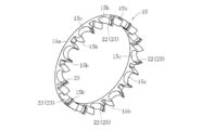
- FIG. 4 is a cross-sectional view taken along the line BB of FIG. It is a perspective view of the said holder
- It is a perspective view of the 1st modification of a maintenance machine.
- FIG. 1 shows a bearing according to the present invention, and this bearing is arranged on the outer surface of an inner ring 12 having an inner rolling surface 12a formed on the outer diameter surface thereof, and on the outer surface of the inner ring 12 and on the outer diameter rolling surface 13a.
- a plurality of balls 14 movably interposed between the inner rolling surface 12 a of the inner ring 12 and the outer rolling surface 13 a of the outer ring 13.
- a resin retainer 15 that holds the balls 14 at equal intervals in the circumferential direction.
- Either the outer ring 13 or the inner ring 12 is attached to a fixed part such as a housing, and the other is attached to a rotating part such as a rotating shaft.
- the crown-shaped cage 15 disposed between the inner ring 12 and the outer ring 13 is spaced apart from the main part 15 a having an annular shape and one axial surface of the main part 15 a.
- a pair of elastic pieces 15b that are integrally projected in the circumferential direction and are recessed between the pair of elastic pieces 15b and open to the outer diameter side and the inner diameter side. 15c is provided, and the ball 14 is rotatably held in the pocket 15c.
- the cage 15 may be made of a resin material using carbon fiber as a reinforcing material, or may be made of engineering plastic as the cage material. When carbon fibers are used, they may be long fibers or short fibers.
- Engineering plastic engineering plastic is a synthetic resin that has excellent heat resistance and can be used in fields where strength is required. Further, a resin having increased heat resistance and strength is called a super engineering plastic, and this super engineering plastic may be used.
- Engineering plastics include polycarbonate (PC), polyamide 6 (PA6), polyamide 66 (PA66), polyacetal (POM), modified polyphenylene ether (m-PPE), polybutylene terephthalate (PBT), GF reinforced polyethylene terephthalate (GF- PET) and ultra high molecular weight polyethylene (UHMW-PE).
- Super engineering plastics include polysulfone (PSF), polyethersulfone (PES), polyphenylene sulfide (PPS), polyarylate (PAR), polyamideimide (PAI), polyetherimide (PEI), and polyetheretherketone.
- PEEK liquid crystal polymer
- LCP liquid crystal polymer
- thermoplastic polyimide TPI
- PBI polybenzimidazole
- TPX polymethylbenten
- PCT poly1,4-cyclohexanedimethylene terephthalate
- PA46 polyamide 46
- PA6T polyamide 6T
- PA9T polyamide 9T
- PA11,12 polyamide 11,12
- PPA polyphthalamide
- seal members 16 for sealing the annular space between the inner ring 12 and the outer ring 13 are arranged on both sides in the axial direction of the inner ring 12 and the outer ring 13 as shown in FIG.
- the seal member 16 includes a metal core 16a and an elastic body 16b integrally vulcanized and bonded to the metal core 16a.
- a base end portion of the seal member 16 is attached to an inner diameter end portion of the outer ring 13, and a distal end portion is an inner ring 12.
- a seal lip 16c is formed in contact with the outer diameter end.
- the outer ring 13 to which the base end portion of the seal member 16 is mounted is the fixed side
- the inner ring 12 with which the seal lip 16c contacts is the rotating side.
- the inner ring 12 rotates while maintaining the state in which the seal lip 16 c at the tip of the seal member 16 is in sliding contact with the outer diameter end of the inner ring 12. This prevents foreign matters such as water and dust from entering the inside of the bearing or leakage of a lubricant such as grease from the inside of the bearing to the outside.
- the grease is a semi-solid lubricant composed of a base oil, a thickener and an additive, and it is necessary to select a grease suitable for the application depending on the combination thereof.
- Mineral oil is generally used as the base oil, but synthetic oils such as silicone oil, diester oil and fluorine oil are also used to improve heat resistance and low temperature fluidity.
- Thickeners include various metal soap groups, non-metal soap groups, and complex groups, which affect properties such as mechanical stability, water resistance, and operating temperature range.
- Additives include extreme pressure additives, antioxidants, rust inhibitors, and the like, and extreme pressure additives improve characteristics against impact loads and heavy loads. Antioxidants prevent oxidative deterioration when not replenished for a long time. The rust inhibitor prevents rusting of the bearing and its surroundings.
- the retainer 15 has a thickness reduction that makes the retainer axial thickness thinner than the conventional retainer shown in FIGS. 12A and 12B at the pocket-to-pocket portion 20 between the pockets 15c adjacent to each other along the circumferential direction. Is going.
- grooves 23 and 23 constituting a grease inflow path 22 are formed in the pocket inner surface 18 of the cage 15, that is, the inner surface of the elastic piece 15b.
- the cross-sectional shape of the bottom surfaces of the grooves 23 and 23 is a flat circular arc surface.
- one pocket 15c is viewed inward in the radial direction from the outer peripheral side, as shown in FIGS. 4A and 4A, it looks like a circle with a part of the pocket 15c missing.
- the grooves 23, 23 are arranged on a straight line passing through the circular center O and parallel to the bottom surface of the cage (the surface on the side opposite to the elastic side).
- the groove 23 from the inner diameter side to the outer diameter side (outer diameter side to inner diameter side). 23 is formed.
- the circular locus L is the fastest part.
- the b is preferably set to 1/70 to 1/30 of the cage PCD (see FIG. 2).
- the stress generated by centrifugal force is concentrated on the bottom of the cage pocket. Therefore, at the time of high-speed rotation, a certain amount of thickness is required at the inner surface bottom corresponding portion of the pocket, and the thickness in the cage axial direction is required to be 1/70 or more in the PCD ratio.
- a seal member 16 is required as shown in FIG. However, the interference between the seal member 16 and the cage 15 causes heat generation, and it is desirable to drive the seal member 16 without contact.
- the cage PCD refers to a pitch circle diameter of an imaginary circle formed by continuously connecting the centers of the pockets 15c along the circumferential direction.
- the weld 15 is inevitable because the cage 15 is formed in an annular shape. I have to take a design that brings the weld to the side.
- the strength reduction rate of the inter-pocket part 20 which is a weld part can be understood from the weld strength experiment result (stress part distribution diagram) shown in FIG.
- the retainer 15 is made of polyamide 9T (PA9T), which is one of super engineer plastics. It is about 1 / 3.5 compared with the welded portion and the non-welded portion.
- the thickness necessary for the weld strength is a ⁇ b ⁇ 3.5, but if the thickness necessary for the generated stress is taken into consideration, a ⁇ b ⁇ 3.5 / 4. Therefore, A becomes the cage PCD ratio 1 / (70 ⁇ 0.875) to 1 / (30 ⁇ 0.875), and 1/62 to 1/26 is set.
- the bearing using the cage of the present invention is most suitable for a motor main shaft used at high speed rotation such as EV and HEV.
- the weight By reducing the thickness in the cage axial direction at the pocket-to-pocket portion 20, the weight can be reduced, and by setting a> b and c> 0, the cage annular strength can be reduced. Decline can be prevented. That is, it is possible to reduce the weight while securing the strength as the cage 15.
- the thickness of the inter-pocket portion 20 in the cage axial direction as much as possible (thinning)
- the weight can be reduced and the influence of centrifugal force can be reduced, but the annular strength may be reduced. For this reason, it is preferable to maintain the relationship of a> b and to satisfy c> 0.
- the rigidity of this portion can be secured, and this portion can be secured even during high-speed rotation. Can be effectively prevented, interference with the seal member for sealing the annular space of the bearing can be prevented, and heat generation due to interference can be effectively prevented.
- the strength of the inter-pocket region 21 as the weld portion can be ensured by setting the thickness of the inter-pocket region 20 in the cage axial direction to 1/62 to 1/26 of the cage PCD.
- the cage 15 is made of a resin material using carbon fiber as a reinforcing material, the cage 15 is stable in strength and excellent in durability. In particular, when an engineering plastic is used for the cage material, it is excellent in strength.
- FIG. 6 to 8 show modified examples of the groove 23.
- FIG. 6 shows a cross-sectional shape of a flat triangle
- FIG. 7 shows a cross-sectional shape of a trapezoid.
- the groove 23 shown in FIGS. 5 to 7 was opened on the inner diameter surface of the cage and the outer diameter surface of the cage.
- the outer diameter surface of the cage does not open.
- a protrusion 25 is provided in place of the groove 23.
- two pieces are provided at predetermined intervals along the position where the groove 23 is provided in each elastic piece 15b, that is, the fastest part of the ball rotation speed, along the axial direction of the cage.
- the protrusion 25 can be constituted by a short cylindrical body, a hemispherical shape, a truncated cone shape, a pyramid shape, or the like. Further, the interval h between the protrusions 25 is not limited to e shown in FIG. 4B.
- the grease inflow path 22 can be configured by the groove 23 formed on the inner surface 18 of the pocket 15c, or can be configured by the protrusion 25 formed on the inner surface 18 of the pocket 15c. Excellent.
- the present invention is not limited to the above-described embodiment, and various modifications can be made, and the number of pockets 15c of the cage 15 depends on the number of balls held. Can be changed in various ways. Each dimension a, b, c, e, f, etc. can be variously changed depending on the material used. Further, in the cage 15 of the present invention, even when the ball 14 as a rolling element approaches due to high-speed rotation, the grease is interposed between the inner surface 18 of the pocket 15 c and the ball 14 via the grease inflow path 22. The bearing using this cage is optimal for an electric motor used at high speed rotation such as EV or HEV because it can flow in and prevent the oil film from being cut.
- an electric motor used at high speed rotation such as EV or HEV because it can flow in and prevent the oil film from being cut.
- This bearing is optimal for electric motors used at high speeds such as EVs and HEVs, but is not limited to EVs and HEVs, and can be used for other purposes, for example, for supporting spindles of machine tools.
Landscapes
- Engineering & Computer Science (AREA)
- General Engineering & Computer Science (AREA)
- Mechanical Engineering (AREA)
- Rolling Contact Bearings (AREA)
Abstract
本発明は、全体を円環状に形成してその円周方向複数箇所にそれぞれが外径側と内径側とに開口したポケット(15c)を有し、ポケット(15c)で転動体としてのボール(14)を転動自在に保持する冠形状の軸受用保持器であって、ポケットの内面(18)とボールとの間にグリース流入路(22)を設けた軸受用保持器に関する。
Description
本発明は、軸受用保持器および軸受に関する。
近年、電気自動車(electric car)(EV)やハイブリッドカー(Hybrid Electric Vehicle)(HEV)等の電動機を有する車両が増加している。EVやHEVにおいては電費向上のため、電動機(モータ)が高速回転で使用される。このため、モータ主軸に使用される軸受も高速回転に適したものが必要となる。
ところで、従来の軸受(ボール軸受)は、図11に示すように、外径面に内側転走面2aが形成された内輪2と、その内輪2の外側に配置され、内径面に外側転走面3aが形成された外輪3と、内輪2の内側転走面2aと外輪3の外側転走面3aとの間に転動自在に介在された複数のボール4と、内輪2と外輪3との間に配され、各ボール4を円周方向等間隔に保持する樹脂製の保持器5とで主要部が構成されている。この外輪3あるいは内輪2のいずれか一方がハウジングなどの固定部分に装着され、他方が回転軸などの回転部分に装着される。
この内輪2と外輪3との間に配された冠形状の保持器5は、図12A及び図12Bに示すように、円環状をなす主部5aと、その主部5aの軸方向片面に互いに間隔をあけて円周方向等配で一体的に突設された一対ずつの弾性片5bとで構成され、これら一対ずつの弾性片5bの間に凹設されて外径側と内径側とに開口したポケット5cを備え、そのポケット5cでボール4を転動自在に保持する。
また、内輪2と外輪3の軸方向両側には、図11に示すようにその内輪2と外輪3との間の環状空間を密封するためのシール部材6が配置されている。このシール部材6は、芯金6aとその芯金6aに一体的に加硫接着された弾性体6bとからなり、その基端部が外輪3の内径端部に装着され、先端部が内輪2の外径端部に接触するシールリップ6cが形成されている。なお、図示のボール軸受1では、シール部材6の基端部が装着された外輪3が固定側であり、シールリップ6cが接触する内輪2が回転側である。
このボール軸受1の運転中、シール部材6の先端のシールリップ6cが内輪2の外径端部に摺接した状態を維持しながら、内輪2が回転する。これにより、水やダスト等の異物が軸受内部に侵入したり、あるいは、軸受内部からグリース等の潤滑剤が外部へ漏れたりすることを未然に防止するようにしている。
このような軸受が高速回転で使用されると、樹脂製の保持器では、遠心力により変形し、他部品を干渉することで摩耗粉が発生し、異常発熱が懸念され、寿命が短くなるおそれがあった。そこで、従来には、高速回転時に発生する遠心力により問題を解決したものが種々提案されている(特許文献1~特許文献4)。
特許文献1に記載の保持器は、円環部、及び、円環部の一側面から延出する片持ち状の複数の柱部を備え、円環部と隣接する柱部とで形成される各ポケットにボールを転動自在に収容するものである。そして、保持器は、遠心力による半径方向変形を考慮し、予め所定の遠心力による変形分だけ円環部から柱部の先端部分に向かって半径方向内方に傾斜させた構造とし、高速回転時に遠心力により変形した時に傾き分が補正され、柱部が軸方向略水平となって、ボールと保持器のポケットとの接触位置が適正になるようにしたものである。
特許文献2に記載の保持器は、合成樹脂製の組み合わせ保持器にて、係合部である第2素子の鉤部と被係合部である第1素子の段部とを係合するに際し、係合部の弾性変形量を小さく又はなくすようにしたものである。また、両素子が係合した状態において、貫通孔には突起部との隙間を埋める固定片が挿入され、固定片により両素子を一体に固定することで、両素子の係合力を高めるものである。
特許文献3は、その図1に記載のように、冠形保持器の内径部に、凹部(ぬすみ部)を設けることによって、高速回転時に、ボールの自転速度の速い部分に当接させないようにするものである。すなわち、冠形保持器のポケットを構成する内壁面とボールとの干渉部分を減らすものである。
特許文献4は、ボール軸受用冠型保持器の合成樹脂よりも剛性の高い環状の金属板からなる補助リングを接着等にて一体化するものである。これによって、保持器の剛性を高めるものである。また、特許文献5の記載の軸受用保持器は、合成樹脂製保持器本体と、この保持器本体に連結される金属製変形防止部材とからなるものである。このため、特許文献5に記載の軸受用保持器は、特許文献4に記載のボール軸受用冠型保持器と同様保持器の剛性を高めるものである。また、従来には、保持器内径を落とし、重量を減らすことで遠心力を制御するものもある。
特許文献1に記載のものでは、予め所定の遠心力による変形分だけ円環部から柱部の先端部分に向かって半径方向内方に傾斜させる必要があり、生産性に劣るとともに、実際の変形量と、想定した変形量とが一致しない場合があり、機能として安定しない。
また、特許文献2、特許文献4、及び特許文献5に記載のものでは、部品点数が多く、生産性に劣るとともに、コスト高となっていた。しかも、特許文献2に記載のものでは、グリース潤滑では、空間容積が少なくなって、寿命面でも不利になる。
特許文献3に記載のものでは、溝加工部が内径部のみに限定されるため、回転時に大きなボール遅れ進みが発生した場合、保持器と転動体との接触面積が減少せず、発熱大となるおそれがある。しかも、遠心力影響の対策を実施していないため、ポケット内径部を溝で落とした分だけ保持器拡径が促進し、転動体の動きが不安定になる。このため、保持器外径が外輪内径に接触し、発熱大となる可能性がある。また、遠心力を制御するものでは、保持器強度が低下するおそれがある。
本発明は、上記課題に鑑みて、高速回転による変形影響を抑制し、グリースの潤滑状態を改善し、長寿命となる軸受用保持器およびこのような保持器を用いた軸受を提供する。
本発明の軸受用保持器は、全体を円環状に形成してその円周方向複数箇所にそれぞれが外径側と内径側とに開口したポケットを有し、前記ポケットで転動体としてのボールを転動自在に保持する冠形状の軸受用保持器であって、前記ポケットの内面と前記ボールとの間にグリース流入路を設けたものである。
本発明の軸受用保持器によれば、高速回転によって、転動体であるボールが接近した状態となっても、グリース流入路を介してポケットの内面とボールとの間にグリースが流入し、油膜切れを防止できる。
前記グリース流入路としては、前記ポケットの内面に形成される溝にて構成したり、前記ポケットの内面に形成される突起にて構成したりできる。また、前記グリース流入路が、ボール自転速度の最速部位に設けるのが好ましい。
ポケット間部位において保持器軸方向肉厚を薄くする肉抜きを行うとともに、ポケット間部位の保持器軸方向肉厚をaとし、ポケットの内面底対応部位の保持器軸方向肉厚をbとし、ポケット間部位の肉抜き端面から前記最速部位までの寸法をcとしたときに、a>bでかつc>0となるのが好ましい。
ポケットの内面底対応部位の保持器軸方向肉厚を、保持器PCDの1/70~1/30に設定したり、ポケット間の保持器軸方向肉厚を、保持器PCDの1/62~1/26に設定したりできる。ここで、保持器PCDとは、各ポケットの中心を周方向に沿って相互に連続させて構成した仮想円のピッチ円直径をいう。
遠心力による発生応力は保持器ポケット部底に集中する。従って高速回転時においては、ポケットの内面底対応部位にはある程度の肉厚が必要であり、その保持器軸方向肉厚としてPCD比で1/70以上が必要である。また、本保持器はグリース潤滑を想定している為、シールドまたはシールが必要になる。しかしながら、シール部材と保持器が干渉することは発熱要因となり、シール部材とは非接触で駆動することが望ましい。このため、ポケットの内面底対応部位の保持器軸方向肉厚としてPCD比1/30以下とすることが必要である。
また、遠心力による発生応力は保持器ポケット部底に集中するが、保持器が円環で構成されていることからウェルドの発生は避けられなく、構造上、ポケット間部位にウェルドを持ってくる設計を取らざるを得ない。ウェルド部の強度低下率は、PA9T等のエンジニアプラスチックでは、非ウェルド部と比較して最大で1/3.5程度である。これ対して、ポケット底部とポケット間部位に発生する応力差は、ポケット間部位の保持器軸方向肉厚をaとし、ポケット底部の保持器軸方向肉厚をbとしたときに、ほぼa:b=1:4となる。したがって、ウェルド強度的に必要な肉厚はa≧b×3.5であるが、発生応力的に必要な肉厚を加味すると、a≧b×3.5/4となる。よってaは保持器PCD比1/(70×0.875)~1/(30×0.875)となり、1/62~1/26を設定することとなる。
保持器としては、強化材にカーボンファイバーを用いた樹脂材にて構成されるものであっても、その保持器材料をエンジニアリングプラスチックとしたものであってもよい。エンジニアリングプラスチック(エンプラ)とは、合成樹脂のなかで主に耐熱性が優れており、強度が必要とされる分野に使うことのできるものをいう。さらに耐熱性・強度を増した樹脂をスーパーエンプラと呼び、このスーパーエンプラを使用してもよい。
本発明の軸受は前記軸受用保持器を用いたものである。
本発明では、油膜切れを防止できるので、摩耗粉の発生や異常発熱を防止でき、グリース劣化を抑制できて、長寿命化を図ることができる。
グリース流入路は、遠心力による転動体の保持器接触による油切れを防止するものであるので、前記ポケットの内面に形成される溝にて構成したり、前記ポケットの内面に形成される突起にて構成したりでき、設計性に優れる。
グリース流入路をボール自転速度の最速部位に設ければ、油膜切れを有効に防止でき、より長寿命化を図ることができる。
ポケット間部位において保持器軸方向肉厚を薄くする肉抜きを行うことによって、軽量化を図ることができ、しかも、a>bでかつc>0とすることによって、保持器円環強度の低下を防止できる。すなわち、保持器としての強度を確保しつつ、軽量化を図ることができる。軽量化することによって、遠心力に変形を低減させることができ、他部材への干渉や保持器自体の破損等を防止できる。
ポケットの内面底対応部位の保持器軸方向肉厚を、保持器PCDの1/45~1/15に設定したことにより、この部位の剛性を確保でき、高速回転時においても、この部位の変形を有効に防止でき、かつ、軸受の環状空間を密封するためのシール部材との干渉を防止でき、干渉による発熱を有効に防止できる。
ポケット間部位の保持器軸方向肉厚を、保持器PCDの1/40~1/13に設定したことにより、ウェルド部であるポケット間部位の強度を確保できる。
保持器としては、強化材にカーボンファイバーを用いた樹脂材にて構成されるものであれば、強度的に安定して耐久性に優れたものとなる。特に、保持器材料にエンジニアリングプラスチックを用いると、強度的に優れたものとなる。
前記軸受用保持器を用いた軸受では、高速回転で使用されても耐久性に優れ、長い寿命化を図ることができる。このため、EVやHEV等の高速回転で使用される電動機用に最適である。また、このような長寿命化を達成できる軸受を形成する場合、保持器のみ変更すればよいので、生産性に優れ、高コスト化になるのを抑えることができる。
以下本発明の実施の形態を図1~図9に基づいて説明する。図1は、本発明に係る軸受を示し、この軸受は、外径面に内側転走面12aが形成された内輪12と、その内輪12の外側に配置され、内径面に外側転走面13aが形成された外輪13と、内輪12の内側転走面12aと外輪13の外側転走面13aとの間に転動自在に介在された複数のボール14と、内輪12と外輪13との間に配され、各ボール14を円周方向等間隔に保持する樹脂製の保持器15とで主要部が構成されている。この外輪13あるいは内輪12のいずれか一方がハウジングなどの固定部分に装着され、他方が回転軸などの回転部分に装着される。
この内輪12と外輪13との間に配された冠形状の保持器15は、図2に示すように、円環状をなす主部15aと、その主部15aの軸方向片面に互いに間隔をあけて円周方向等配で一体的に突設された一対ずつの弾性片15bとで構成され、これら一対ずつの弾性片15bの間に凹設されて外径側と内径側とに開口したポケット15cを備え、そのポケット15cでボール14を転動自在に保持する。
保持器15は、強化材にカーボンファイバーを用いた樹脂材にて構成されるものであっても、保持器材料をエンジニアリングプラスチックとしたものであってもよい。カーボンファイバーを用いる場合、長繊維であっても短繊維であってもよい。エンジニアリングプラスチック(エンプラ)とは、合成樹脂のなかで主に耐熱性が優れており、強度が必要とされる分野に使うことのできるものをいう。さらに耐熱性・強度を増した樹脂をスーパーエンプラと呼び、このスーパーエンプラを使用してもよい。
エンジニアリングプラスチックには、ポリカーボネート(PC)、ポリアミド6(PA6)、ポリアミド66(PA66)、ポリアセタール(POM)、変性ポリフェニレンエーテル(m-PPE)、ポリブチレンテレフタレート(PBT)、GF強化ポリエチレンテレフタレート(GF-PET)、超高分子量ポリエチレン(UHMW-PE)等がある。また、スーパーエンジニアリングプラスチックには、ポリサルホン(PSF)、ポリエーテルサルホン(PES)、ポリフェニレンサルファイド(PPS)、ポリアリレート(PAR)、ポリアミドイミド(PAI)、ポリエーテルイミド(PEI)、ポリエーテルエーテルケトン(PEEK)、液晶ポリマー(LCP)、熱可塑性ポリイミド(TPI)、ポリベンズイミダゾール(PBI)、ポリメチルベンテン(TPX)、ポリ1,4-シクロヘキサンジメチレンテレフタレート(PCT)、ポリアミド46(PA46)、ポリアミド6T(PA6T)、ポリアミド9T(PA9T)、ポリアミド11,12(PA11,12)、フッ素樹脂、ポリフタルアミド(PPA)等がある。
また、内輪12と外輪13の軸方向両側には、図1に示すようにその内輪12と外輪13との間の環状空間を密封するためのシール部材16が配置されている。このシール部材16は、芯金16aとその芯金16aに一体的に加硫接着された弾性体16bとからなり、その基端部が外輪13の内径端部に装着され、先端部が内輪12の外径端部に接触するシールリップ16cが形成されている。なお、図示のボール軸受11では、シール部材16の基端部が装着された外輪13が固定側であり、シールリップ16cが接触する内輪12が回転側である。
このボール軸受11の運転中、シール部材16の先端のシールリップ16cが内輪12の外径端部に摺接した状態を維持しながら、内輪12が回転する。これにより、水やダスト等の異物が軸受内部に侵入したり、あるいは、軸受内部からグリース等の潤滑剤が外部へ漏れたりすることを未然に防止するようにしている。
ところで、グリースは基油・増ちょう剤・添加剤から構成されている半固体状の潤滑剤であり、その組合せにより用途に適したグリースを選定する必要がある。基油には一般的に鉱油が多く使われているが、耐熱性・低温流動性を向上させるためにシリコーン油・ジエステル油・フッ素油などの合成油も使用されている。増ちょう剤は各種の金属石鹸基・非金属石鹸基・複合基などがあり、機械的安定性・耐水性・使用温度範囲などの特性を左右するものである。添加剤には、極圧添加剤、酸化防止剤、及び防錆剤等があり、極圧添加剤は、衝撃荷重や重荷重に対する特性を向上させる。酸化防止剤は、長期間無補給の場合の酸化劣化を防止する。防錆剤は、軸受及びその周囲の錆を防止する。
保持器15は、周方向に沿って隣り合うポケット15c、15cの間のポケット間部位20において保持器軸方向肉厚を、図12A及び図12Bに示す従来の保持器よりも薄くする肉抜きを行っている。この場合、図4Aに示すように、ポケット間部位20の保持器軸方向肉厚をaとし、ポケット15cの内面底対応部位21の保持器軸方向肉厚をbとした場合に、a>bとする。例えば、a:b=1.5~3.0:1程度とする。
また、保持器15のポケット内面18、すなわち、弾性片15bの内面には、図3~図5に示すように、グリース流入路22を構成する溝23,23が形成されている。この溝23,23の底面断面形状は、扁平円弧面とされる。一つのポケット15cを、外周側から径方向内方に見た場合、図4A及び図4Aに示すように、ポケット15cの一部が欠けた円形に見える。そして、溝23,23は、円形の中心Oを通り、保持器底面(反弾性片側の面)と平行な直線上に配置される。すなわち、保持器底面(反弾性片側の面)19と平行な円形軌跡L上に、弾性片15bの内径面に沿って、内径側から外径側(外径側から内径側)に溝23,23が形成される。この円形軌跡L上が最速部位となる。
溝23の幅寸法(保持器軸方向寸法)をe(図4B参照)とし、ボール直径をD(図4A参照)とした場合、D:e=3.8~4.6:1程度とする。また、溝23の深さをf(図4B参照)した場合、e:f=7~9:1程度とする。このように設定することによって、ボールが溝23側に接触したとしても、この溝23によって、ボール14との間に空間が形成され、グリース流入路22を構成することができる。さらに、ポケット間部位20の肉抜き端面20aから前記最速部位(円形軌跡L)までの寸法をc(図4A参照)としたときに、c>0としている。
ところで、前記bとしては、保持器PCD(図2参照)の1/70~1/30に設定するのが好ましい。遠心力による発生応力は保持器ポケット部底に集中する。従って高速回転時においては、ポケットの内面底対応部位にはある程度の肉厚が必要であり、その保持器軸方向肉厚としてPCD比で1/70以上が必要である。また、本保持器はグリース潤滑を想定している為、図1に示すように、シール部材16必要になる。しかしながら、シール部材16と保持器15が干渉することは発熱要因となり、シール部材16とは非接触で駆動することが望ましい。このため、ポケット15cの内面底対応部位の保持器軸方向肉厚としてPCD比1/30以下とすることが必要である。ここで、保持器PCDとは、各ポケット15cの中心を周方向に沿って相互に連続させて構成した仮想円のピッチ円直径をいう。
また、遠心力による発生応力は保持器ポケット部底に集中するが、保持器15が円環で構成されていることからウェルドの発生は避けられなく、構造上、保持器15のポケット間部位20にウェルドを持ってくる設計を取らざるを得ない。
ところで、ウェルド部であるポケット間部位20の強度低下率は、図10に示すウェルド強度実験結果(応力部分布図)から分かる。この場合、保持器15は、スーパエンジニアプラスチックの一つであるポリアミド9T(PA9T)を用いた。ウェルド部と非ウェルド部と比較して1/3.5程度である。対して、ポケット底部とポケット間部位20に発生する応力差は、a=bの時の解析結果から、ほぼa:b=1:4となる。したがって、ウェルド強度的に必要な肉厚はa≧b×3.5であるが、発生応力的に必要な肉厚を加味すると、a≧b×3.5/4となる。よってAは保持器PCD比1/(70×0.875)~1/(30×0.875)となり、1/62~1/26を設定することとなる。
高速回転によって、転動体であるボール14が接近した状態となっても、グリース流入路を介してポケット15cの内面18とボール14との間にグリースが流入し、油膜切れを防止できる。このため、摩耗粉の発生や異常発熱を防止でき、グリース劣化を抑制できて、長寿命化を図ることができる。このため、本発明の保持器を用いた軸受は、EVやHEV等の高速回転で使用されるモータ主軸に使用されるものに最適となる。
ポケット間部位20において保持器軸方向肉厚を薄くする肉抜きを行うことによって、軽量化を図ることができ、しかも、a>bでかつc>0とすることによって、保持器円環強度の低下を防止できる。すなわち、保持器15としての強度を確保しつつ、軽量化を図ることができる。ポケット間部位20の保持器軸方向肉厚をできる限り薄く(肉抜き)することで軽量化し、遠心力影響を低減させることができるが、円環強度が低下するおそれがある。このため、a>bの関係を保ち、かつ、c>0とするのが好ましい。
ポケット15cの内面底対応部位21の保持器軸方向肉厚を、保持器PCDの1/70~1/30に設定したことにより、この部位の剛性を確保でき、高速回転時においても、この部位の変形を有効に防止でき、かつ、軸受の環状空間を密封するためのシール部材との干渉を防止でき、干渉による発熱を有効に防止できる。
ポケット間部位20の保持器軸方向肉厚を、保持器PCDの1/62~1/26に設定したことにより、ウェルド部であるポケット間部位21の強度を確保できる。
保持器15としては、強化材にカーボンファイバーを用いた樹脂材にて構成されるものでれば、強度的に安定して耐久性に優れたものとなる。特に、保持器材料にエンジニアリングプラスチックを用いると、強度的に優れたものとなる。
図6から図8までは溝23の変形例を示し、図6は断面形状が扁平三角形状とされ、図7は断面形状が台形形状とされたものである。また、図5~図7までの溝23では、保持器内径面及び保持器外径面に開口したものであったが、図8に示す溝23では、保持器内径面には開口するが、保持器外径面には開口しない形状となっている。この図8に示す溝23の断面形状として円弧形状とされている。
この図6~図8に示す溝23においても、転動体であるボール14が接近した状態となっても、グリース流入路22を介してポケット15cの内面18とボール14との間にグリースが流入し、油膜切れを防止でき、前記図5等に示す溝23同様の作用効果を奏するものである。
次に、図9は、溝23に代えて突起25を設けている。この場合、各弾性片15bに前記溝23が設けられる位置、つまり、ボール自転速度の最速部位、保持器軸方向に沿って所定間隔で2個ずつ配設される。
このように、溝23に代えて突起25を設けた場合であっても、前記ポケット15cの内面と前記ボール14との間に隙間を設けることができて、グリース流入路22が形成される。各弾性片15bの突起25の間隔hとしては、前記図4Bで示すeとほぼ一致する。また、突起25の高さ寸法(ポケット内面からの突出量)として、グリース流入路22を構成できる隙間が形成できればよい。
このため、突起25としては、短円柱体、半球体形状、円錐台形状、及び角錐体形状等にて構成できる。また、突起25の間隔hとしても、前記図4Bで示すeに限るものではない。
このように、グリース流入路22は、前記ポケット15cの内面18に形成される溝23にて構成したり、前記ポケット15cの内面18に形成される突起25にて構成したりでき、設計性に優れる。
以上、本発明の実施形態につき説明したが、本発明は前記実施形態に限定されることなく種々の変形が可能であって、保持器15のポケット15cの数は、保持されるボール数に応じて種々変更できる。また、各寸法a、b、c、e、f等は、使用する材質によって、種々変更できる。また、本発明の保持器15では、高速回転によって、転動体であるボール14が接近した状態となっても、グリース流入路22を介してポケット15cの内面18とボール14との間にグリースが流入し、油膜切れを防止できるものであるので、この保持器を用いた軸受は、EVやHEV等の高速回転で使用される電動機に最適である。
この軸受は、EVやHEV等の高速回転で使用される電動機に最適であるが、EVやHEVに限るものではなく、これ以外の用途、例えば工作機械の主軸等の支持に用いることもできる。
14 ボール
15 保持器
15c ポケット
18 ポケット内面
20 ポケット間部位
20a 肉抜き端面
21 内面底対応部位
22 グリース流入路
23 溝
25 突起
15 保持器
15c ポケット
18 ポケット内面
20 ポケット間部位
20a 肉抜き端面
21 内面底対応部位
22 グリース流入路
23 溝
25 突起
Claims (10)
- 全体を円環状に形成してその円周方向複数箇所にそれぞれが外径側と内径側とに開口したポケットを有し、前記ポケットで転動体としてのボールを転動自在に保持する冠形状の軸受用保持器であって、
前記ポケットの内面と前記ボールとの間にグリース流入路を設けたことを特徴とする軸受用保持器。 - 前記グリース流入路が、前記ポケットの内面に形成される溝にて構成されることを特徴とする請求項1に記載の軸受用保持器。
- 前記グリース流入路が、前記ポケットの内面に形成される突起にて構成されることを特徴とする請求項1に記載の軸受用保持器。
- 前記グリース流入路が、ボール自転速度の最速部位に設けたことを特徴とする請求項1~請求項3のいずれか1項に記載の軸受用保持器。
- ポケット間部位において保持器軸方向肉厚を薄くする肉抜きを行うとともに、ポケット間部位の保持器軸方向肉厚をaとし、ポケットの内面底対応部位の保持器軸方向肉厚をbとし、ポケット間部位の肉抜き端面から前記最速部位までの寸法をcとしたときに、a>bでかつc>0となることを特徴とする請求項1~請求項4のいずれか1項に記載の軸受用保持器。
- ポケットの内面底対応部位の保持器軸方向肉厚を、保持器PCDの1/70~1/30に設定したことを特徴とする請求項1~請求項5のいずれか1項に記載の軸受用保持器。
- ポケット間の保持器軸方向肉厚を、保持器PCDの1/62~1/26に設定したことを特徴とする請求項1~請求項6のいずれか1項に記載の軸受用保持器。
- 強化材にカーボンファイバーを用いた樹脂材にて構成されることを特徴とする請求項1~請求項7のいずれか1項に記載の軸受用保持器。
- 保持器材料をエンジニアリングプラスチックとしたことを特徴とする請求項1~請求項8のいずれか1項に記載の軸受用保持器。
- 前記請求項1~請求項9のいずれか1項に記載の軸受用保持器を用いたことを特徴とする軸受。
Priority Applications (3)
| Application Number | Priority Date | Filing Date | Title |
|---|---|---|---|
| US15/556,418 US10570961B2 (en) | 2015-03-11 | 2016-02-17 | Retainer for bearing and bearing |
| CN201680014371.2A CN107407333B (zh) | 2015-03-11 | 2016-02-17 | 球轴承用保持器以及轴承 |
| DE112016001138.5T DE112016001138T5 (de) | 2015-03-11 | 2016-02-17 | Lagerkäfig und Lager |
Applications Claiming Priority (2)
| Application Number | Priority Date | Filing Date | Title |
|---|---|---|---|
| JP2015-048436 | 2015-03-11 | ||
| JP2015048436A JP6608151B2 (ja) | 2015-03-11 | 2015-03-11 | 軸受用保持器および軸受 |
Publications (1)
| Publication Number | Publication Date |
|---|---|
| WO2016143472A1 true WO2016143472A1 (ja) | 2016-09-15 |
Family
ID=56880419
Family Applications (1)
| Application Number | Title | Priority Date | Filing Date |
|---|---|---|---|
| PCT/JP2016/054513 WO2016143472A1 (ja) | 2015-03-11 | 2016-02-17 | 軸受用保持器および軸受 |
Country Status (5)
| Country | Link |
|---|---|
| US (1) | US10570961B2 (ja) |
| JP (1) | JP6608151B2 (ja) |
| CN (1) | CN107407333B (ja) |
| DE (1) | DE112016001138T5 (ja) |
| WO (1) | WO2016143472A1 (ja) |
Families Citing this family (7)
| Publication number | Priority date | Publication date | Assignee | Title |
|---|---|---|---|---|
| DE102018108523A1 (de) * | 2018-04-10 | 2019-10-10 | Gebr. Reinfurt Gmbh & Co. Kg | Kugellager-Käfig und Kugellager |
| US11828328B2 (en) | 2019-01-29 | 2023-11-28 | Ntn Corporation | Ball bearing |
| US11078959B1 (en) * | 2020-06-10 | 2021-08-03 | Schaeffler Technologies AG & Co. KG | High speed bearing with single piece wide plastic cage |
| IT202000021943A1 (it) | 2020-09-18 | 2022-03-18 | Skf Ab | Gabbia per cuscinetto e cuscinetto |
| DE112022000678T5 (de) * | 2021-01-18 | 2023-11-02 | Nsk Ltd. | Kronenförmiger Kugellagerkäfig und Kugellager |
| JP2022134949A (ja) * | 2021-03-04 | 2022-09-15 | Ntn株式会社 | 保持器及び玉軸受 |
| JP2023044983A (ja) | 2021-09-21 | 2023-04-03 | Ntn株式会社 | 転がり軸受 |
Citations (6)
| Publication number | Priority date | Publication date | Assignee | Title |
|---|---|---|---|---|
| JP2003232361A (ja) * | 2002-02-12 | 2003-08-22 | Nsk Ltd | 玉軸受用保持器及び玉軸受 |
| JP2003239984A (ja) * | 2002-02-19 | 2003-08-27 | Koyo Seiko Co Ltd | 玉軸受 |
| WO2010032577A1 (ja) * | 2008-09-18 | 2010-03-25 | Ntn株式会社 | 転がり軸受用保持器およびこれを備える転がり軸受 |
| JP2011202799A (ja) * | 2010-03-04 | 2011-10-13 | Ntn Corp | スラスト円筒ころ軸受 |
| JP2012107764A (ja) * | 2012-03-09 | 2012-06-07 | Ntn Corp | 円すいころ軸受用保持器 |
| JP2013068249A (ja) * | 2011-09-21 | 2013-04-18 | Jtekt Corp | 玉軸受及び玉軸受用の保持器 |
Family Cites Families (15)
| Publication number | Priority date | Publication date | Assignee | Title |
|---|---|---|---|---|
| JPS4636035Y1 (ja) | 1968-06-26 | 1971-12-11 | ||
| JP2638811B2 (ja) * | 1987-06-30 | 1997-08-06 | 日本電気株式会社 | 無線伝送基地局 |
| JPH0648180Y2 (ja) * | 1989-04-07 | 1994-12-12 | 光洋精工株式会社 | 冠形保持器 |
| DE19937664A1 (de) * | 1999-08-10 | 2001-02-15 | Schaeffler Waelzlager Ohg | Schnappkäfig für Kugellager |
| JP4017827B2 (ja) * | 2000-01-28 | 2007-12-05 | Ntn株式会社 | 玉軸受 |
| GB0214207D0 (en) * | 2002-06-19 | 2002-07-31 | Sarnatech Bnl Ltd | Improved bearing |
| JP4424092B2 (ja) | 2004-06-28 | 2010-03-03 | 株式会社ジェイテクト | 合成樹脂製の冠形保持器 |
| WO2007058351A1 (ja) | 2005-11-18 | 2007-05-24 | Nsk Ltd. | 樹脂製保持器及び転がり軸受 |
| JP2007285506A (ja) | 2006-01-24 | 2007-11-01 | Nsk Ltd | 軸受用保持器及び転がり軸受 |
| JP2007315587A (ja) * | 2006-04-28 | 2007-12-06 | Nachi Fujikoshi Corp | 合成樹脂製ベアリング用リテーナ |
| JP2008185107A (ja) | 2007-01-29 | 2008-08-14 | Nsk Ltd | 玉軸受 |
| DE102007061589B4 (de) * | 2007-01-29 | 2017-06-22 | Nsk Ltd. | Kugellager und Halterungskonstruktion |
| JP4636035B2 (ja) | 2007-02-22 | 2011-02-23 | 日本精工株式会社 | 転がり軸受 |
| JP2009281399A (ja) | 2008-05-19 | 2009-12-03 | Nsk Ltd | 深溝玉軸受用保持器及び深溝玉軸受 |
| JP2010276052A (ja) * | 2009-05-26 | 2010-12-09 | Ntn Corp | 玉軸受用保持器および玉軸受 |
-
2015
- 2015-03-11 JP JP2015048436A patent/JP6608151B2/ja active Active
-
2016
- 2016-02-17 WO PCT/JP2016/054513 patent/WO2016143472A1/ja active Application Filing
- 2016-02-17 US US15/556,418 patent/US10570961B2/en active Active
- 2016-02-17 CN CN201680014371.2A patent/CN107407333B/zh active Active
- 2016-02-17 DE DE112016001138.5T patent/DE112016001138T5/de active Pending
Patent Citations (6)
| Publication number | Priority date | Publication date | Assignee | Title |
|---|---|---|---|---|
| JP2003232361A (ja) * | 2002-02-12 | 2003-08-22 | Nsk Ltd | 玉軸受用保持器及び玉軸受 |
| JP2003239984A (ja) * | 2002-02-19 | 2003-08-27 | Koyo Seiko Co Ltd | 玉軸受 |
| WO2010032577A1 (ja) * | 2008-09-18 | 2010-03-25 | Ntn株式会社 | 転がり軸受用保持器およびこれを備える転がり軸受 |
| JP2011202799A (ja) * | 2010-03-04 | 2011-10-13 | Ntn Corp | スラスト円筒ころ軸受 |
| JP2013068249A (ja) * | 2011-09-21 | 2013-04-18 | Jtekt Corp | 玉軸受及び玉軸受用の保持器 |
| JP2012107764A (ja) * | 2012-03-09 | 2012-06-07 | Ntn Corp | 円すいころ軸受用保持器 |
Also Published As
| Publication number | Publication date |
|---|---|
| JP6608151B2 (ja) | 2019-11-20 |
| JP2016169766A (ja) | 2016-09-23 |
| CN107407333A (zh) | 2017-11-28 |
| DE112016001138T5 (de) | 2017-11-30 |
| US10570961B2 (en) | 2020-02-25 |
| CN107407333B (zh) | 2020-02-18 |
| US20180106295A1 (en) | 2018-04-19 |
Similar Documents
| Publication | Publication Date | Title |
|---|---|---|
| JP6608151B2 (ja) | 軸受用保持器および軸受 | |
| JP5876237B2 (ja) | 玉軸受用の合成樹脂製保持器および玉軸受 | |
| EP1972801B1 (en) | Ball bearing for spindle pivot section of machine tool, and spindle pivot device of machine tool, using the same | |
| TW201819790A (zh) | 滾動軸承用保持器及滾動軸承 | |
| US11255381B2 (en) | Rolling bearing and cage | |
| CN107559309B (zh) | 用于曲轴轴承组件的保持架 | |
| JP2016023647A (ja) | 玉軸受 | |
| JP2017203551A (ja) | 玉軸受、それを用いたモータ及び主軸装置 | |
| KR20110054023A (ko) | 롤링 베어링 | |
| JP5894491B2 (ja) | 転がり軸受 | |
| JP2013145012A (ja) | スラストころ軸受およびスラストころ軸受装置 | |
| JP2007057038A (ja) | 円すいころ軸受 | |
| JP2021076187A (ja) | 転がり軸受及び保持器 | |
| US11236782B2 (en) | Rolling bearing | |
| JP6529209B2 (ja) | アンギュラ玉軸受 | |
| TWI678478B (zh) | 滾珠軸承用保持器 | |
| JP6493580B2 (ja) | アンギュラ玉軸受 | |
| JP2018091399A (ja) | 転がり軸受用保持器及びそれを備えた転がり軸受 | |
| JP2015187494A (ja) | 玉軸受用の樹脂製保持器、及び玉軸受 | |
| CN211778525U (zh) | 倾斜型保持器及角接触球轴承 | |
| JP2008175239A (ja) | 玉軸受用冠型保持器及び玉軸受 | |
| JP2015124885A (ja) | 転がり軸受用の樹脂製保持器、及び転がり軸受 | |
| WO2016052232A1 (ja) | 玉軸受用保持器 | |
| KR101986988B1 (ko) | 볼 베어링 케이지 | |
| JP2018204740A (ja) | 転がり軸受用保持器および転がり軸受 |
Legal Events
| Date | Code | Title | Description |
|---|---|---|---|
| 121 | Ep: the epo has been informed by wipo that ep was designated in this application |
Ref document number: 16761444 Country of ref document: EP Kind code of ref document: A1 |
|
| WWE | Wipo information: entry into national phase |
Ref document number: 15556418 Country of ref document: US |
|
| WWE | Wipo information: entry into national phase |
Ref document number: 112016001138 Country of ref document: DE |
|
| 122 | Ep: pct application non-entry in european phase |
Ref document number: 16761444 Country of ref document: EP Kind code of ref document: A1 |