WO2016143196A1 - エアバッグ装置 - Google Patents
エアバッグ装置 Download PDFInfo
- Publication number
- WO2016143196A1 WO2016143196A1 PCT/JP2015/082218 JP2015082218W WO2016143196A1 WO 2016143196 A1 WO2016143196 A1 WO 2016143196A1 JP 2015082218 W JP2015082218 W JP 2015082218W WO 2016143196 A1 WO2016143196 A1 WO 2016143196A1
- Authority
- WO
- WIPO (PCT)
- Prior art keywords
- airbag
- region
- inflator
- folded
- protector cloth
- Prior art date
- Legal status (The legal status is an assumption and is not a legal conclusion. Google has not performed a legal analysis and makes no representation as to the accuracy of the status listed.)
- Ceased
Links
Images





Classifications
-
- B—PERFORMING OPERATIONS; TRANSPORTING
- B60—VEHICLES IN GENERAL
- B60R—VEHICLES, VEHICLE FITTINGS, OR VEHICLE PARTS, NOT OTHERWISE PROVIDED FOR
- B60R21/00—Arrangements or fittings on vehicles for protecting or preventing injuries to occupants or pedestrians in case of accidents or other traffic risks
- B60R21/02—Occupant safety arrangements or fittings, e.g. crash pads
- B60R21/16—Inflatable occupant restraints or confinements designed to inflate upon impact or impending impact, e.g. air bags
- B60R21/20—Arrangements for storing inflatable members in their non-use or deflated condition; Arrangement or mounting of air bag modules or components
- B60R21/201—Packaging straps or envelopes for inflatable members
-
- B—PERFORMING OPERATIONS; TRANSPORTING
- B60—VEHICLES IN GENERAL
- B60R—VEHICLES, VEHICLE FITTINGS, OR VEHICLE PARTS, NOT OTHERWISE PROVIDED FOR
- B60R21/00—Arrangements or fittings on vehicles for protecting or preventing injuries to occupants or pedestrians in case of accidents or other traffic risks
- B60R21/02—Occupant safety arrangements or fittings, e.g. crash pads
- B60R21/16—Inflatable occupant restraints or confinements designed to inflate upon impact or impending impact, e.g. air bags
- B60R21/20—Arrangements for storing inflatable members in their non-use or deflated condition; Arrangement or mounting of air bag modules or components
- B60R21/205—Arrangements for storing inflatable members in their non-use or deflated condition; Arrangement or mounting of air bag modules or components in dashboards
-
- B—PERFORMING OPERATIONS; TRANSPORTING
- B60—VEHICLES IN GENERAL
- B60R—VEHICLES, VEHICLE FITTINGS, OR VEHICLE PARTS, NOT OTHERWISE PROVIDED FOR
- B60R21/00—Arrangements or fittings on vehicles for protecting or preventing injuries to occupants or pedestrians in case of accidents or other traffic risks
- B60R21/02—Occupant safety arrangements or fittings, e.g. crash pads
- B60R21/16—Inflatable occupant restraints or confinements designed to inflate upon impact or impending impact, e.g. air bags
- B60R21/23—Inflatable members
- B60R21/231—Inflatable members characterised by their shape, construction or spatial configuration
- B60R21/233—Inflatable members characterised by their shape, construction or spatial configuration comprising a plurality of individual compartments; comprising two or more bag-like members, one within the other
-
- B—PERFORMING OPERATIONS; TRANSPORTING
- B60—VEHICLES IN GENERAL
- B60R—VEHICLES, VEHICLE FITTINGS, OR VEHICLE PARTS, NOT OTHERWISE PROVIDED FOR
- B60R21/00—Arrangements or fittings on vehicles for protecting or preventing injuries to occupants or pedestrians in case of accidents or other traffic risks
- B60R21/02—Occupant safety arrangements or fittings, e.g. crash pads
- B60R21/16—Inflatable occupant restraints or confinements designed to inflate upon impact or impending impact, e.g. air bags
- B60R21/23—Inflatable members
- B60R21/237—Inflatable members characterised by the way they are folded
-
- B—PERFORMING OPERATIONS; TRANSPORTING
- B60—VEHICLES IN GENERAL
- B60R—VEHICLES, VEHICLE FITTINGS, OR VEHICLE PARTS, NOT OTHERWISE PROVIDED FOR
- B60R21/00—Arrangements or fittings on vehicles for protecting or preventing injuries to occupants or pedestrians in case of accidents or other traffic risks
- B60R21/02—Occupant safety arrangements or fittings, e.g. crash pads
- B60R21/16—Inflatable occupant restraints or confinements designed to inflate upon impact or impending impact, e.g. air bags
- B60R21/23—Inflatable members
- B60R21/231—Inflatable members characterised by their shape, construction or spatial configuration
- B60R21/233—Inflatable members characterised by their shape, construction or spatial configuration comprising a plurality of individual compartments; comprising two or more bag-like members, one within the other
- B60R2021/23308—Inflatable members characterised by their shape, construction or spatial configuration comprising a plurality of individual compartments; comprising two or more bag-like members, one within the other the individual compartments defining the external shape of the bag
Definitions
- the present invention relates to an airbag apparatus for protecting a vehicle occupant in the event of a collision, and more particularly to an airbag apparatus in which a folded airbag is assembled and held by a protector cloth.
- an airbag device as an occupant protection device in a vehicle or the like holds a folded airbag, an inflator that supplies gas to the airbag, a retainer that supports the airbag and the inflator, and a folded shape of the airbag.
- a protector cloth is provided (see, for example, Patent Document 1).
- an airbag device in which the shape of the airbag is asymmetrical in consideration of the curved shape of the front window (see, for example, Patent Documents 2 to 5).
- the height differs between the left and right.
- the protector cloth is applied, the height of the airbag folded body is increased by the spontaneous restoring force from the folded state of the airbag. The height is uniform and the height is adjusted to the higher one.
- JP 2005-82021 A JP 2010-162945 A JP-A-2005-335652 Japanese Patent Laid-Open No. 10-71920 JP-A-6-278559
- the present invention has been made in view of the above-described conventional situation, and an object of the present invention is to provide an airbag device in which the height of an airbag folded body with a protector cloth is different for each part.
- An airbag device of the present invention encloses a folded airbag, an inflator that inflates the airbag, a retainer to which the airbag and the inflator are attached, and a folded body of the airbag.
- a retainer cloth that retains its shape, and the retainer includes first and second side portions that face each other, and third and fourth side portions that intersect with the first and second side portions.
- the protector cloth extends from the first side part side to the second side part side and encloses the airbag folded body, wherein the protector cloth includes the airbag A first region enclosing the third side portion side of the folding body; and a second region enclosing the fourth side portion side, the first region and the second region.
- a slit is provided between the first region and the second region.
- the slit extends from the one end to the middle of the direction connecting the one end and the other end.
- the length from the one end to the other end of the region is shorter than the length from the one end to the other end of the second region.
- the airbag has an asymmetric shape of the third side side portion inflated and the fourth side side portion inflated.
- a package volume of a portion encapsulated in the first region of the airbag folded body is smaller than a package volume of a portion encapsulated in the second region. It is characterized by that.
- a first insertion port is provided on the third side portion side of the retainer, and a second insertion port is provided on the fourth side portion side. The leading side of the inflator is inserted into the airbag folding body through the first insertion port and the second insertion port.
- the locking member is a bolt that fixes the airbag to the retainer together with the inflator, and is disposed on the one end side and the other end side of the first region of the protector cloth. Each provided hole is passed through the bolt.
- the airbag is provided with an inflator opening, a pressing ring that presses an edge of the inflator opening from the inside of the airbag is disposed, and the bolt is It is erected on the holding ring.
- At least four bolts are erected from the pressing ring, and two of the bolts are positioned on the first side portion side, and the other two The bolts are located on the second side portion side.
- one end and the other end of the first region and the second region of the protector cloth are locked to the locking member, and the first region is one side of the airbag folded body (the third side of the retainer). And the second region encloses the other side of the airbag folded body (the fourth side portion side of the retainer) to keep the folded shape.
- the length from one end to the other end of the first region of the protector cloth is shorter than the length from one end to the other end of the second region, and between the first region and the second region, from one end A slit extending halfway in the direction connecting the one end and the other end is provided. Therefore, the height of the portion encapsulated in the first region of the protector cloth in the airbag folded body can be made lower than the portion encapsulated in the second region.
- the airbag device of the present invention is suitable for application when the third side side portion inflated shape and the fourth side side portion inflated shape of the airbag are asymmetric.
- the airbag device of the present invention is applied to the case where the package volume of the portion encapsulated in the first region of the airbag folded body is smaller than the package volume of the portion encapsulated in the second region. Is preferred.
- the first insertion port is provided on the third side portion side of the retainer, and the second insertion port is provided on the fourth side portion side, Via the first insertion port and the second insertion port, the leading sides of the first and second inflators are inserted into the airbag folded body, respectively.
- the protector cloth can be easily locked by passing holes provided in the first and second regions of the protector cloth through bolts that fix the airbag to the retainer together with the inflator. be able to.
- FIG. 1A is a longitudinal sectional view of an airbag device according to an embodiment
- FIG. 1B is a partially enlarged view of FIG. 1A. It is a disassembled perspective view from the upper part of the airbag folding body before the protector cloth
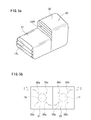
- FIG. 5A is a perspective view of the airbag folded body when the protector cloth is encapsulated according to the embodiment, and FIG. 5B is a plan view thereof.
- FIG. 1 is a longitudinal sectional view of an airbag apparatus according to an embodiment
- FIG. 1a is a sectional view taken along a line II in FIG. 5b
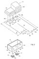
- 2 is a perspective view from above of the airbag folded body before the protector cloth is wrapped
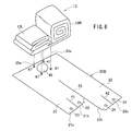
- FIG. 3 is a perspective view from below of the airbag folded body when the protector cloth is wrapped
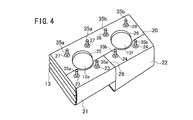
- FIG. 4 is a view of the protector cloth being wrapped.
- the perspective view from below of an airbag folding body and FIG. 5a, 5b are the perspective views and top views from the upper part.
- the airbag device 1 includes a retainer 12, an airbag 13 attached to the retainer 12 by pressing rings 14 a and 14 b, inflators 16 and 17 for inflating the airbag 13, and a module cover 19.
- a protector cloth 20 that retains the shape of the airbag 13 is provided.
- the airbag device 1 is a passenger seat airbag device installed on an instrument panel in front of a passenger seat of an automobile.
- the airbag 13 is folded into a folded body 13L with a small bulk (package volume) on the left half side, folded into a folded body 13R with a large bulk (package volume) on the right half side, and each is wrapped with a protector cloth 20 to retain its shape. Has been.
- the retainer 12 has a substantially rectangular parallelepiped box shape with an open upper surface as shown in FIG.
- the bottom surface of the retainer 12 includes a first side part 12a and a second side part 12b facing each other, a third side part 12c and a fourth side in a direction intersecting the first side part 12a and the second side part 12b. And a side portion 12d.
- Two inflator insertion ports 12 e and 12 f are provided on the bottom surface of the retainer 12.
- the inflator insertion port 12e and the inflator insertion port 12f are arranged so that a line connecting the centers thereof is parallel to the first side portion 12a and the second side portion 12b, and the inflator insertion port 12e is the third portion.
- the inflator insertion port 12f is located on the fourth side portion 12d side.
- An insertion hole 12g of a later-described bolt 35a is provided around the inflator insertion port 12e, and an insertion hole 12h of a later-described bolt 35b is provided around the inflator insertion port 12f.
- the inflator 16 has a flange 16a, and four bolts 35a erected from the pressing ring 14a are passed through the airbag 13, the protector cloth 20, the retainer 12, and the flange 16a, and the nut 36a is tightened. Yes. Thereby, the inflator 16 is fixed to the retainer 12 together with the airbag 13.
- the inflator 17 has a flange 17a.
- Four bolts 35b erected from the holding ring 14b are passed through the airbag 13, the protector cloth 20, the retainer 12, and the flange 17a, and the nut 36b is tightened. It is included. Thereby, the inflator 17 is fixed to the retainer 12 together with the airbag 13.
- two bolts 35a are located on the first side portion 12a side, and the other two bolts 35a are on the second side portion 12b side.
- two bolts 35b are located on the first side portion 12a side, and the other two bolts 35b are on the second side portion. Located on the part 12b side.
- the airbag 13 is formed by stitching a plurality of panels into a bag shape.
- the area of the panel constituting the airbag 13 is larger on the fourth side portion 12d side than on the third side portion 12c side. Therefore, the airbag 13 inflated and deployed by supplying gas from the inflators 16 and 17 is deployed on the fourth side portion 12d side to be larger than the third side portion 12c side.
- the expansion shape on the part 12c side and the expansion shape on the fourth side part 12d side are different.
- the airbag 13 is provided with openings for inserting inflators on the third side portion 12c side and the fourth side portion 12d side, and there are insertion holes for the bolts 35a and 35b around the opening. Is provided.
- the holding rings 14a and 14b are inserted into the airbag 13 from the opening for inserting the inflator of the airbag 13, and the bolts 35a and 35b are passed through the bolt insertion holes of the airbag 13 and the locking holes 27 and 28 of the protector cloth 20, respectively. After that, the airbag 13 is folded.
- the left half side (third side part 12c side) of the airbag 13 is folded in a bellows shape to form a left half side folded body 13L, and the right half side (fourth side part 12d side). Is folded into a roll shape to form the right half side folded body 13R, but the folding method is not particularly limited, and other folding methods such as a combination of bellows folding and roll folding may be used.
- the right half side folded body 13R has a larger package volume (folded bulk) than the left half side folded body 13L, and the retainer 12 The height from the bottom of is increased.
- the protector cloth 20 for enveloping the folded body of the airbag 13 and maintaining the shape thereof is made of, for example, a base fabric made of the same material as the airbag 13.
- the protector cloth 20 has a belt-like first region 21 that encloses the left half-side folded body 13L of the airbag 13 and a belt-like second region 22 that encloses the right half-side folded body 13R.
- a slit 29 extending from one end of the protector cloth 20 to the middle of the direction connecting the one end and the other end is provided. Therefore, the distal end side of the first region 21 and the distal end side of the second region 22 are divided, and the proximal end side of the first region 21 and the proximal end side of the second region 22 are continuous.
- two locking holes 23 into which the bolts 35 a can be inserted are provided on the distal end side in the longitudinal direction of the first region 21, and an opening 25 for inserting the inflator 16 is provided on the proximal end side. Is provided. Around the opening 25, four locking holes 27 into which bolts 35a can be inserted are provided. In addition, a substantially semicircular arc-shaped notch 21 a that matches the shape of the opening 25 is formed on the distal end side of the first region 21.
- Two locking holes 24 into which bolts 35b can be inserted are provided on the distal end side in the longitudinal direction of the second region 22, and an opening 26 for inserting the inflator 17 is provided on the proximal end side.
- an opening 26 for inserting the inflator 17 is provided on the proximal end side.
- four locking holes 28 into which the bolts 35b can be inserted are provided.
- a substantially semicircular arc-shaped notch 22 a that matches the shape of the opening 26 is formed on the distal end side of the second region 22.
- the folding body of the airbag 13 is larger in volume in the right half side folding body 13R than in the left half side folding body 13L. Therefore, the length L2 of the second region 22 encapsulating the right half side folded body 13R is longer than the length L1 from one end to the other end of the first region 21 enclosing the left half side folded body 13L. It has become.
- the holding rings 14 a and 14 b are inserted into the airbag 13 through the openings 25 and 26, and the bolts 35 a and 35 b are inserted into the bolt insertion holes of the airbag 13.
- the bolts 35 a and 35 b are inserted into the locking holes 27 and 28 of the protector cloth 20.
- the left half side of the airbag 13 is bellows folded to form a left half side folded body 13L, the left half side folded body 13L is encapsulated in the first region 21 of the protector cloth 20, and the locking hole 23 is formed. Thread through the bolt 35a.
- the right half side of the airbag 13 is roll-folded to form a right half side folded body 13R, the right half side folded body 13R is encapsulated in the second region 22, and the locking hole 24 is passed through the bolt 35b. .
- the airbag folded body is retained by the protector cloth 20. Since the slit 29 is formed between the first region 21 and the second region 22, the first region 21 and the second region 22 are independently independent of the left half side folded body 13L and the right half side folded body. 13R can be encapsulated.
- the protector cloth 20 extends from the first side part 12a side to the second side part 12b side to enclose the airbag folded body,
- the locking holes 23 and 27 at both ends and the locking holes 24 and 28 at both ends of the second region 22 are passed through the bolts 35a and 35b and locked.
- the folding body of the airbag 13 has the thickness of the right half side folding body 13R larger than that of the left half side folding body 13L, and accordingly, a protector that encloses the airbag folding body.
- the cross 20 has a length L2 from one end to the other end of the second region 22 longer than a length L1 from one end to the other end of the first region 21. Therefore, the left half-side folded body 13L and the right half-side folded body 13R can be encapsulated and held with appropriate tightening strength.
- the airbag folded body thus formed is accommodated in the retainer 12, and the bolts 35a and 35b are inserted into the insertion holes 12g and 12h, respectively.
- the inflators 16 and 17 are attached to the retainer 12.
- the leading side of the inflator 16 is inserted into the airbag folded body through the insertion port 12e of the retainer 12 and the opening 25 of the protector cloth.
- the front side of the inflator 17 is inserted into the airbag folded body through the insertion port 12f and the opening 26.
- the bolts 35a and 35b are passed through the flanges 16a and 17a and the bolt insertion holes of the inflators 16 and 17, and the nuts 36a and 36b are tightened into the bolts 35a and 35b. Thereby, the airbag 13 and the inflators 16 and 17 are fixed to the retainer 12.
- the airbag 13 is inflated by injecting gas from the inflators 16 and 17 in the event of a vehicle collision. At this time, the protector cloth 20 is torn, and the airbag 13 pushes open the module cover 19 and deploys in the vehicle compartment. In addition, it is preferable to provide a slit for starting tearing in the protector cloth.
- the small left-side folded body 13L is encapsulated in the short first region 21, and the large right-half folded body 13R is covered in the long second region 22. Since it is wrapped, the left half-side folded body 13L and the right half-side folded body 13R can be firmly held with substantially the same degree of tightening by the single protector cloth 20. Therefore, the storage capacity of the airbag device can be reduced and can be easily stored in the retainer 12.
- instrument panel of an automobile may be provided so as to be inclined so that the central part in the vehicle body width direction is higher and the vehicle side is lower, and the module cover 19 is correspondingly provided as shown in FIG. 1a. May be inclined so that the center side in the vehicle width direction is higher.
- the height of the top surface of the left half-side folded body 13L is lower than the top surface of the right half-side folded body 13R, so that the left half-side folded body 13L hits the module cover 19. There is no.
- the circular inflator insertion openings 25 and 26 are provided on the base end side of the protector cloth 20, but as shown in FIGS. 6 and 7, the first region 21 and the second region 22. It is good also as the protector cloth 20A by which the circular arc-shaped notches 21b and 22b were each formed in the base end side. Two locking holes 27 and 28 are provided at the edges of the notches 21b and 22b.
- the airbag 13 may have the same inflated shape on the third side portion 12c side and the fourth side portion 12d side.
- the area of the panel constituting the airbag 13 is the same on the third side portion 12c side and the fourth side portion 12d side.
- the airbag 13 has the same inflated shape on the third side portion 12c side and the fourth side portion 12d side, the airbag 13 is folded depending on the folding method and the number of cloths (patches) used. May vary in thickness. Due to these differences, even when the right half-side folded body 13R is thicker than the left half-side folded body 13L, the left half-side folded body 13L and the right half-side folded body 13R can be obtained by using the protector cloth 20. Can be encapsulated with an appropriate tightening strength and held in shape.
- the number of inflators attached to the airbag device may be one.
- one opening 45 (or an arc-shaped notch) is provided in the central portion on the base end side of the protector cloth 20 ⁇ / b> B, and a bolt is provided around the opening 45.
- a locking hole 47 that can be inserted is provided.
- Short slits 41 and 42 are provided on the distal end sides of the first region 21 and the second region 22, respectively, toward the proximal end side, whereby two leaf tongue portions are provided on the distal end sides of the regions 21 and 22, respectively. 21s, 21t, 22s, and 22t are formed.
- the respective locking holes 47 of the protector cloth 20B are respectively passed through the bolts 35a.
- the airbag 13 is folded to form a left half-side folded body 13L, the left half-side folded body 13L of the airbag 13 is encapsulated in the first region 21 of the protector cloth 20B, and the tongue pieces 21s, 21t
- Each insertion hole 23 is hung on one bolt 35a on the left half side.
- the right half side folded body 13R is formed, the right half side folded body 13R is encapsulated in the second region 22 of the protector cloth 20B, and the insertion holes 24 of the tongue pieces 22s and 22t are respectively provided on the right half side.
- the bolt 35a is hung.
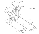
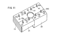
- the protector cloth 20 ⁇ / b> C includes four locking holes 47 provided around the opening 45, and four locking holes 47 provided on both ends in the short-side direction from these locking holes 47. Have.
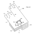
- Protector cloth 20, 20A, 20B, 20C and airbag 13 may be sewn and joined. For example, as shown in FIG. 12, sewing 50 is applied to the peripheral edge of the opening 45 of the protector cloth 20B and the peripheral edge of the inflator insertion opening of the airbag 13, and the protector cloth 20B and the airbag 13 are joined. Is done.
- the distal end side of the first region 21 and the distal end side of the second region 22 of the protector cloth 20, 20 ⁇ / b> A, 20 ⁇ / b> B, 20 ⁇ / b> C are divided, and the proximal end side of the first region 21 and the base of the second region 22 are separated.
- the end side is continuous, the base end side may be divided, and the first region 21 and the second region 22 may be separated.
- the airbag device is for the passenger seat, but other airbag devices may be used.
- Airbag apparatus 12 Retainer 13 Airbag 14a, 14b Retaining ring 16, 17 Inflator 20, 20A, 20B, 20C Protector cloth 29 Slit 35a, 35b Bolt 36a, 36b Nut
Landscapes
- Engineering & Computer Science (AREA)
- Mechanical Engineering (AREA)
- Air Bags (AREA)
Abstract
プロテクタクロスをかけたエアバッグ折り畳み体の高さが部分毎に異なるエアバッグ装置を提供する。エアバッグ装置1は、エアバッグ13及びインフレータ16、17が取り付けられたリテーナ12と、エアバッグ13の折り畳み体を被包するプロテクタクロス20とを備える。リテーナ12は、第1~第4の側辺部12a、12b、12c、12dを有する。プロテクタクロス20は、左半側折り畳み体13Lを被包する第1領域21、及び右半側折り畳み体14Rを被包する第2領域22を有する。第1領域21及び第2領域22は、それぞれ一端側及び他端側がボルト35a、35bに係止されている。第1領域21と第2領域22との間にスリット29が設けられており、第1領域21の一端から他端までの長さL1は、第2領域22の一端から他端までの長さL2より短くなっている。
Description
本発明は、車両乗員を衝突時等に保護するためのエアバッグ装置に係り、特に折り畳まれたエアバッグがプロテクタクロスによって保形されて組み立てられているエアバッグ装置に関する。
一般に、車両等における乗員の保護装置であるエアバッグ装置は、折り畳まれたエアバッグと、エアバッグにガスを供給するインフレータと、エアバッグ及びインフレータを支持するリテーナと、エアバッグの折り畳み形状を保持するプロテクタクロスと、を備えている(例えば特許文献1参照)。
エアバッグ装置として、乗員の拘束性能を向上させるために、フロントウィンドウの湾曲形状を考慮してエアバッグの形状を左右非対称形状としたものが公知である(例えば特許文献2~5参照)。
このような左右非対称形状のエアバッグを折り畳むと、左右で高さ(厚み)が異なるが、プロテクタクロスをかけた状態では、エアバッグの折り畳み状態からの自発的復元力によりエアバッグ折り畳み体の高さは一様となり、その高さは高い方に合わせたものとなる。
上述したように、従来は、エアバッグを折り畳んで1枚のプロテクタクロスをかけた時に、エアバッグ折り畳み体の高さを部分毎に変えることが出来なかった。
本発明は、上記従来の実状に鑑みてなされたものであり、プロテクタクロスをかけたエアバッグ折り畳み体の高さが部分毎に異なるエアバッグ装置を提供することを課題とする。
本発明のエアバッグ装置は、折り畳まれたエアバッグと、該エアバッグを膨張させるインフレータと、該エアバッグ及び該インフレータが取り付けられたリテーナと、該エアバッグの折り畳み体を被包し、この折り畳み形状を保形しているプロテクタクロスと、を備え、該リテーナは、対向する第1及び第2の側辺部と、これらと交差方向の第3及び第4の側辺部とを有しており、該プロテクタクロスは該第1の側辺部側から第2の側辺部側まで延在してエアバッグ折り畳み体を被包しているエアバッグ装置において、該プロテクタクロスは、前記エアバッグ折り畳み体の前記第3の側辺部側を被包する第1領域、及び前記第4の側辺部側を被包する第2領域を有しており、該第1領域及び該第2領域は、それぞれ一端側及び他端側が係止部材に係止されており、該第1領域と該第2領域との間に、該一端から該一端と他端とを結ぶ方向の途中まで延在したスリットが設けられており、該第1領域の該一端から他端までの長さは、該第2領域の該一端から他端までの長さより短いことを特徴とする。
本発明の一態様によるエアバッグ装置において、前記エアバッグは前記第3の側辺部側の膨張形状と前記第4の側辺部側の膨張形状とが非対称である。
本発明の一態様によるエアバッグ装置は、前記エアバッグ折り畳み体のうち、前記第1領域で被包された部分のパッケージボリュームが、前記第2領域で被包された部分のパッケージボリュームよりも小さいことを特徴とする。
本発明の一態様によるエアバッグ装置において、前記リテーナの前記第3の側辺部側に第1差込口が設けられ、前記第4の側辺部側に第2差込口が設けられており、該第1差込口及び第2差込口を介して、それぞれインフレータの先頭側が前記エアバッグ折り畳み体の内部に差し込まれている。
本発明の一態様によるエアバッグ装置において、前記係止部材は、前記エアバッグを前記インフレータとともに前記リテーナに固定するボルトであり、前記プロテクタクロスの前記第1領域の前記一端側及び他端側にそれぞれ設けられた孔が該ボルトに掛け通されている。
本発明の一態様によるエアバッグ装置において、前記エアバッグに、インフレータ用開口が設けられており、エアバッグ内側から該インフレータ用開口の縁部を押さえる押さえリングが配置されており、前記ボルトは、該押さえリングに立設されている。
本発明の一態様によるエアバッグ装置において、前記押さえリングから少なくとも4本の前記ボルトが立設されており、そのうちの2本のボルトは前記第1の側辺部側に位置し、他の2本のボルトは前記第2の側辺部側に位置している。
本発明によれば、プロテクタクロスの第1領域及び第2領域の一端及び他端が、係止部材に係止され、第1領域がエアバッグ折り畳み体の一側(リテーナの第3の側辺部側)を被包し、第2領域がエアバッグ折り畳み体の他側(リテーナの第4の側辺部側)を被包して、折り畳み形状を保形している。プロテクタクロスの第1領域の一端から他端までの長さは、第2領域の一端から他端までの長さより短くなっており、第1領域と該第2領域との間には、一端から該一端と他端とを結ぶ方向の途中まで延在したスリットが設けられている。そのため、エアバッグ折り畳み体のうち、プロテクタクロスの第1領域で被包された部分の高さを、第2領域で被包された部分よりも低くすることができる。
本発明のエアバッグ装置は、エアバッグの第3の側辺部側の膨張形状と第4の側辺部側の膨張形状とを非対称である場合に適用するのに好適である。
本発明のエアバッグ装置は、エアバッグ折り畳み体のうち、第1領域で被包された部分のパッケージボリュームを、第2領域で被包された部分のパッケージボリュームよりも小さい場合に適用するのに好適である。
本発明の一態様のエアバッグ装置では、リテーナの前記第3の側辺部側に第1差込口が設けられ、第4の側辺部側に第2差込口が設けられており、該第1差込口及び第2差込口を介して、それぞれ第1及び第2のインフレータの先頭側がエアバッグ折り畳み体の内部に差し込まれている。このエアバッグをインフレータとともにリテーナに固定するボルトに、プロテクタクロスの第1領域及び第2領域の一端側及び他端側にそれぞれ設けられた孔を掛け通すことで、プロテクタクロスを簡単に係止することができる。
以下、図面を参照して本発明の実施の形態について説明する。図1は実施の形態に係るエアバッグ装置の縦断面図であり、図1aは図5bのI-I線に対応する箇所での断面図を示している。図2はプロテクタクロス被包前のエアバッグ折り畳み体の上方からの斜視図、図3はプロテクタクロス被包時のエアバッグ折り畳み体の下方からの斜視図、図4はプロテクタクロスが被包されたエアバッグ折り畳み体の下方からの斜視図、図5a,5bは、その上方からの斜視図と平面図である。
エアバッグ装置1は、リテーナ12と、このリテーナ12に対し押さえリング14a、14bによって取り付けられたエアバッグ13と、このエアバッグ13を膨張させるためのインフレータ16、17と、モジュールカバー19と、折り畳まれたエアバッグ13を保形しているプロテクタクロス20等を備えて構成されている。このエアバッグ装置1は、この実施の形態では、自動車の助手席前方のインストルメントパネルに設置される助手席用エアバッグ装置である。エアバッグ13は、左半側が嵩(パッケージボリューム)の小さい折り畳み体13Lに折り畳まれ、右半側が嵩(パッケージボリューム)の大きい折り畳み体13Rに折り畳まれ、それぞれプロテクタクロス20で被包され、保形されている。
リテーナ12は、図2の通り、上面が開放した略直方体形函状である。リテーナ12の底面は、対向する第1側辺部12a及び第2側辺部12bと、第1側辺部12a及び第2側辺部12bと交差する方向の第3側辺部12c及び第4側辺部12dとを有する。リテーナ12の底面には、2つのインフレータ差込口12e、12fが設けられている。インフレータ差込口12eとインフレータ差込口12fとは、その中心を結ぶ線が第1側辺部12a及び第2側辺部12bと平行となるように配置され、インフレータ差込口12eが第3側辺部12c側に位置し、インフレータ差込口12fが第4側辺部12d側に位置する。
インフレータ差込口12eの周囲に後述のボルト35aの挿通孔12gが設けられ、インフレータ差込口12fの周囲に後述のボルト35bの挿通孔12hが設けられている。
インフレータ16は、フランジ16aを有しており、押さえリング14aから立設された4本のボルト35aがエアバッグ13、プロテクタクロス20、リテーナ12及びフランジ16aを通され、ナット36aが締め込まれている。これにより、インフレータ16がエアバッグ13と共にリテーナ12に固定される。
同様に、インフレータ17は、フランジ17aを有しており、押さえリング14bから立設された4本のボルト35bがエアバッグ13、プロテクタクロス20、リテーナ12及びフランジ17aを通され、ナット36bが締め込まれている。これにより、インフレータ17がエアバッグ13と共にリテーナ12に固定される。
押さえリング14aから立設された4本のボルト35aのうち、2本のボルト35aは第1の側辺部12a側に位置し、他の2本のボルト35aは第2の側辺部12b側に位置する。同様に、押さえリング14bから立設された4本のボルト35bのうち、2本のボルト35bは第1の側辺部12a側に位置し、他の2本のボルト35bは第2の側辺部12b側に位置する。
エアバッグ13は、複数枚のパネルを縫合して袋状としたものである。エアバッグ13を構成するパネルの面積は、第3の側辺部12c側よりも、第4の側辺部12d側の方が大きくなっている。そのため、インフレータ16、17によりガスが供給されて膨張展開したエアバッグ13は、第3の側辺部12c側よりも第4の側辺部12d側の方が大きく展開され、第3の側辺部12c側の膨張形状と第4の側辺部12d側の膨張形状とが異なるものとなる。
エアバッグ13には、第3の側辺部12c側と第4の側辺部12d側とにそれぞれインフレータの挿入用の開口が設けられ、その周囲には、前記ボルト35a、35bの挿通孔が設けられている。
エアバッグ13のインフレータ挿入用開口からエアバッグ13内に押さえリング14a、14bを挿入し、各ボルト35a、35bをそれぞれエアバッグ13のボルト挿通孔及びプロテクタクロス20の係止孔27、28に通した後、エアバッグ13を折り畳む。
本実施の形態では、エアバッグ13の左半側(第3の側辺部12c側)を蛇腹状に折り畳んで左半側折り畳み体13Lとし、右半側(第4の側辺部12d側)をロール状に折り畳んで右半側折り畳み体13Rとしているが、折り畳み方は特に限定されず、蛇腹折りとロール折りとを組み合わせたものなど他の折り畳み方でもよい。
この実施の形態では、エアバッグ13は左半側よりも右半側の方が大きいため、右半側折り畳み体13Rは左半側折り畳み体13Lよりもパッケージボリューム(折り畳み嵩)が大きく、リテーナ12の底面からの高さが大きくなっている。
エアバッグ13の折り畳み体を被包し、その形状を保持するためのプロテクタクロス20は、例えばエアバッグ13と同じ素材の基布により構成される。プロテクタクロス20は、エアバッグ13の左半側折り畳み体13Lを被包する帯状の第1領域21、及び右半側折り畳み体13Rを被包する帯状の第2領域22を有する。
第1領域21と第2領域22との間には、プロテクタクロス20の一端から、該一端と他端とを結ぶ方向の途中まで延在したスリット29が設けられている。そのため、第1領域21の先端側と第2領域22の先端側とは分断され、第1領域21の基端側と第2領域22の基端側とは連続したものとなる。
図2に明示の通り、第1領域21の長手方向先端側には、ボルト35aが挿通可能な2個の係止孔23が設けられ、基端側にはインフレータ16の挿入用の開口部25が設けられている。この開口部25の周囲には、ボルト35aが挿通可能な4個の係止孔27が設けられている。また、第1領域21の先端側には、開口部25の形状に合わせた略半円弧状の切欠き21aが形成されている。
第2領域22の長手方向先端側には、ボルト35bが挿通可能な2個の係止孔24が設けられ、基端側にはインフレータ17の挿入用の開口部26が設けられている。この開口部26の周囲には、ボルト35bが挿通可能な4個の係止孔28が設けられている。また、第2領域22の先端側には、開口部26の形状に合わせた略半円弧状の切欠き22aが形成されている。
上述したように、エアバッグ13の折り畳み体は、左半側折り畳み体13Lよりも右半側折り畳み体13Rの方が、嵩が大きくなっている。そのため、左半側折り畳み体13Lを被包する第1領域21の一端から他端までの長さL1より、右半側折り畳み体13Rを被包する第2領域22の長さL2の方が長くなっている。
エアバッグ13を折り畳むには、開口部25、26を通して押さえリング14a、14bをエアバッグ13内に差し込み、ボルト35a、35bをエアバッグ13のボルト挿通孔に挿通する。次いで、図2の通り、プロテクタクロス20の係止孔27、28にボルト35a、35bを挿通する。
続いて、エアバッグ13の左半側を蛇腹折りして左半側折り畳み体13Lを形成し、プロテクタクロス20の第1領域21で左半側折り畳み体13Lを被包し、係止孔23をボルト35aに掛け通す。また、エアバッグ13の右半側をロール折りして右半側折り畳み体13Rを形成し、第2領域22で右半側折り畳み体13Rを被包し、係止孔24をボルト35bに掛け通す。これにより、エアバッグ折り畳み体がプロテクタクロス20によって保形される。第1領域21と第2領域22との間にはスリット29が形成されているため、第1領域21と第2領域22とがそれぞれ独立して左半側折り畳み体13Lと右半側折り畳み体13Rとを被包することができる。
このエアバッグ折り畳み体にあっては、プロテクタクロス20が第1の側辺部12a側から第2の側辺部12b側まで延在してエアバッグ折り畳み体を被包し、第1領域21の両端の係止孔23、27、第2領域22の両端の係止孔24、28が、ボルト35a、35bに掛け通されて係止される。
上述したように、エアバッグ13の折り畳み体は、左半側折り畳み体13Lより右半側折り畳み体13Rの方が厚みが大きくなっており、これに合わせて、エアバッグ折り畳み体を被包するプロテクタクロス20は、第1領域21の一端から他端までの長さL1よりも、第2領域22の一端から他端までの長さL2が長くなっている。そのため、左半側折り畳み体13L及び右半側折り畳み体13Rをそれぞれ適切な締め付け強さにて被包して保形することができる。
このようにして形成されたエアバッグ折り畳み体をリテーナ12内に収容し、ボルト35a、35bを挿通孔12g、12hにそれぞれ挿通する。
次いで、リテーナ12に、インフレータ16、17を装着する。インフレータ16の先頭側が、リテーナ12の差込口12e及びプロテクタクロスの開口部25を介してエアバッグ折り畳み体内に挿入される。また、インフレータ17の先頭側が、差込口12f及び開口部26を介してエアバッグ折り畳み体内に挿入される。
インフレータ16、17のフランジ16a、17a、ボルト挿通孔にボルト35a、35bを通し、ボルト35a、35bにナット36a、36bを締め込む。これにより、リテーナ12にエアバッグ13及びインフレータ16、17が固定される。このリテーナ12にモジュールカバー19を被装することにより、図1に示すエアバッグ装置1が構成される。
このように構成されたエアバッグ装置1にあっては、車両衝突時には、インフレータ16、17がガスを噴出することにより、エアバッグ13が膨張する。この際、プロテクタクロス20は断裂し、エアバッグ13は、モジュールカバー19を押し開け、車両室内に展開する。なお、プロテクタクロスに断裂開始用のスリットを設けておくのが好ましい。
このエアバッグ装置にあっては、上記の通り、嵩の小さい左半側折り畳み体13Lを短い第1領域21で被包し、嵩の大きい右半側折り畳み体13Rを長い第2領域22で被包しているので、1枚のプロテクタクロス20により、左半側折り畳み体13L及び右半側折り畳み体13Rをほぼ同等の締め付け度合にてしっかりと保形することができる。そのため、エアバッグ装置の収納容積を小さくすることができ、リテーナ12内に容易に収納することができる。
なお、自動車のインストルメントパネルは、車体幅方向中央部が高位となり、車体サイド側ほど低位となるように傾斜して設けられることがあり、これに対応して、図1aのようにモジュールカバー19が車体幅方向中央側が高位となるように傾斜した構成とされることがある。
この実施の形態では、左半側折り畳み体13Lの頂面の高さが右半側折り畳み体13Rの頂面よりも低位となっているので、左半側折り畳み体13Lがモジュールカバー19に当ることがない。
図6~9を参照して別の実施の形態について説明する。
上記実施の形態では、プロテクタクロス20の基端側に円形のインフレータ挿通用開口部25、26を設けているが、図6、図7に示すように、第1領域21及び第2領域22の基端側に、それぞれ円弧状の切欠き21b、22bが形成されたプロテクタクロス20Aとしてもよい。係止孔27、28は、この切欠21b、22bの縁部に2個ずつ設けられている。
本発明では、エアバッグ13は、第3の側辺部12c側と第4の側辺部12d側とで膨張形状が同じであってもよい。この場合、エアバッグ13を構成するパネルの面積は、第3の側辺部12c側と、第4の側辺部12d側とで同じになる。このようなエアバッグ13の折り畳み体をプロテクタクロス20で被包する際は、第1領域21の巻き付け力を、第2領域22の巻き付け力よりも大きくする。これにより、エアバッグ折り畳み体のうち、プロテクタクロス20の第1領域21で被包された左半側折り畳み体の嵩を、第2領域22で被包された右半側折り畳み体の嵩よりも小さくすることができる。
エアバッグ13は、第3の側辺部12c側と第4の側辺部12d側とで膨張形状が同じであっても、折り畳み方や使用される布(パッチ)の数の違いにより折り畳み体の厚みが異なる場合がある。これらの違いにより、左半側折り畳み体13Lより右半側折り畳み体13Rの方が厚みが大きくなった場合でも、プロテクタクロス20を用いることで、左半側折り畳み体13L及び右半側折り畳み体13Rをそれぞれ適切な締め付け強さにて被包して保形することができる。
エアバッグ装置に装着されるインフレータは1つであってもよい。この場合、図8、図9に示すように、プロテクタクロス20Bの基端側の中央部に1個の開口部45(又は円弧状切欠き)が設けられ、この開口部45の周囲にボルトが挿通可能な係止孔47が設けられる。第1領域21、第2領域22の先端側には、それぞれ基端側に向って短いスリット41、42が設けられ、これにより、各領域21、22の先端側にそれぞれ2葉の舌片部21s、21t、22s、22tが形成されている。
エアバッグ13を折り畳んでプロテクタクロス20Bで被包する際は、まず、プロテクタクロス20Bの各係止孔47をそれぞれボルト35aに掛け通す。続いて、エアバッグ13を折り畳んで左半側折り畳み体13Lを形成し、プロテクタクロス20Bの第1領域21でエアバッグ13の左半側折り畳み体13Lを被包し、舌片部21s、21tの挿通孔23をそれぞれ左半側の1本のボルト35aに掛ける。また、右半側折り畳み体13Rを形成し、プロテクタクロス20Bの第2領域22で右半側折り畳み体13Rを被包し、舌片部22s、22tの挿通孔24をそれぞれ右半側の1本のボルト35aに掛ける。
図8、図9は、押さえリングから4本のボルト35aが立設された構成を示しているが、ボルトの本数は4本に限定されない。図10、図11はボルトの本数を8本とした例を示す。この場合、プロテクタクロス20Cは、開口部45の周囲に設けられた4つの係止孔47と、これらの係止孔47よりも短手方向両端側に設けられた4つの係止孔47とを有する。
プロテクタクロス20、20A、20B、20Cと、エアバッグ13とを縫製して接合してもよい。例えば、図12に示すように、プロテクタクロス20Bの開口部45の周縁部とエアバッグ13のインフレータ挿入用開口の周縁部とに縫製50が施されて、プロテクタクロス20Bとエアバッグ13とが接合される。
上記実施形態では、プロテクタクロス20、20A、20B、20Cの第1領域21の先端側と第2領域22の先端側とが分断され、第1領域21の基端側と第2領域22の基端側とは連続したものとしていたが、基端側も分断し、第1領域21と第2領域22とを別体としてもよい。
上記説明は、本発明の一例であり、本発明は上記以外の形態とされてもよい。例えば、上記実施の形態では、エアバッグ装置は助手席用であるが、その他のエアバッグ装置であってもよい。
本出願は、2015年3月12日付で出願された日本特許出願2015-049588に基づいており、その全体が引用により援用される。
1 エアバッグ装置
12 リテーナ
13 エアバッグ
14a、14b 押さえリング
16、17 インフレータ
20、20A、20B、20C プロテクタクロス
29 スリット
35a、35b ボルト
36a、36b ナット
12 リテーナ
13 エアバッグ
14a、14b 押さえリング
16、17 インフレータ
20、20A、20B、20C プロテクタクロス
29 スリット
35a、35b ボルト
36a、36b ナット
Claims (7)
- 折り畳まれたエアバッグと、
該エアバッグを膨張させるインフレータと、
該エアバッグ及び該インフレータが取り付けられたリテーナと、
該エアバッグの折り畳み体を被包し、この折り畳み形状を保形しているプロテクタクロスと、
を備え、
該リテーナは、対向する第1及び第2の側辺部と、これらと交差方向の第3及び第4の側辺部とを有しており、
該プロテクタクロスは該第1の側辺部側から第2の側辺部側まで延在してエアバッグ折り畳み体を被包しているエアバッグ装置において、
該プロテクタクロスは、前記エアバッグ折り畳み体の前記第3の側辺部側を被包する第1領域、及び前記第4の側辺部側を被包する第2領域を有しており、
該第1領域及び該第2領域は、それぞれ一端側及び他端側が係止部材に係止されており、
該第1領域と該第2領域との間に、該一端から該一端と他端とを結ぶ方向の途中まで延在したスリットが設けられており、
該第1領域の該一端から他端までの長さは、該第2領域の該一端から他端までの長さより短いことを特徴とするエアバッグ装置。 - 請求項1において、前記エアバッグは前記第3の側辺部側の膨張形状と前記第4の側辺部側の膨張形状とが非対称であることを特徴とするエアバッグ装置。
- 請求項1又は2において、前記エアバッグ折り畳み体のうち、前記第1領域で被包された部分のパッケージボリュームが、前記第2領域で被包された部分のパッケージボリュームよりも小さいことを特徴とするエアバッグ装置。
- 請求項1ないし3のいずれか1項において、前記リテーナの前記第3の側辺部側に第1差込口が設けられ、前記第4の側辺部側に第2差込口が設けられており、
該第1差込口及び第2差込口を介して、それぞれインフレータの先頭側が前記エアバッグ折り畳み体の内部に差し込まれていることを特徴とするエアバッグ装置。 - 請求項1ないし4のいずれか1項において、前記係止部材は、前記エアバッグを前記インフレータとともに前記リテーナに固定するボルトであり、
前記プロテクタクロスの前記第1領域の前記一端側及び他端側にそれぞれ設けられた孔が該ボルトに掛け通されていることを特徴とするエアバッグ装置。 - 請求項5において、前記エアバッグに、前記差込口に重なるインフレータ用開口が設けられており、
エアバッグ内側から該インフレータ用開口の縁部を押さえる押さえリングが配置されており、
前記ボルトは、該押さえリングに立設されていることを特徴とするエアバッグ装置。 - 請求項6において、前記押さえリングから少なくとも4本の前記ボルトが立設されており、そのうちの2本のボルトは前記第1の側辺部側に位置し、他の2本のボルトは前記第2の側辺部側に位置していることを特徴とするエアバッグ装置。
Priority Applications (1)
| Application Number | Priority Date | Filing Date | Title |
|---|---|---|---|
| US15/555,372 US10279767B2 (en) | 2015-03-12 | 2015-11-17 | Airbag device |
Applications Claiming Priority (2)
| Application Number | Priority Date | Filing Date | Title |
|---|---|---|---|
| JP2015-049588 | 2015-03-12 | ||
| JP2015049588A JP6507740B2 (ja) | 2015-03-12 | 2015-03-12 | エアバッグ装置 |
Publications (1)
| Publication Number | Publication Date |
|---|---|
| WO2016143196A1 true WO2016143196A1 (ja) | 2016-09-15 |
Family
ID=56880080
Family Applications (1)
| Application Number | Title | Priority Date | Filing Date |
|---|---|---|---|
| PCT/JP2015/082218 Ceased WO2016143196A1 (ja) | 2015-03-12 | 2015-11-17 | エアバッグ装置 |
Country Status (3)
| Country | Link |
|---|---|
| US (1) | US10279767B2 (ja) |
| JP (1) | JP6507740B2 (ja) |
| WO (1) | WO2016143196A1 (ja) |
Cited By (1)
| Publication number | Priority date | Publication date | Assignee | Title |
|---|---|---|---|---|
| EP3587195A4 (en) * | 2017-02-27 | 2020-10-14 | Autoliv Development AB | LATERAL INFLATABLE SAFETY CUSHION TYPE DEVICE |
Families Citing this family (5)
| Publication number | Priority date | Publication date | Assignee | Title |
|---|---|---|---|---|
| JP6423394B2 (ja) * | 2016-08-04 | 2018-11-14 | トヨタ自動車株式会社 | 助手席用エアバッグ装置 |
| DE102017124581A1 (de) * | 2017-10-20 | 2019-04-25 | Dalphi Metal Espana, S.A. | Umhüllung eines gassacks eines fahrzeuginsassen-rückhaltesystems und verfahren zum verpacken eines gassacks in einer umhüllung |
| US10994687B2 (en) * | 2018-12-11 | 2021-05-04 | Autoliv Asp, Inc. | Airbag compression wrappers and related airbag assemblies |
| US11465580B2 (en) * | 2020-04-08 | 2022-10-11 | Autoliv Asp, Inc. | Bi-directional airbag cushion wrappers and related airbag assemblies and methods |
| US11345302B2 (en) * | 2020-07-27 | 2022-05-31 | ZF Passive Safety Systems US Inc. | Curtain airbag with integral airbag wrap |
Citations (3)
| Publication number | Priority date | Publication date | Assignee | Title |
|---|---|---|---|---|
| JP2004299654A (ja) * | 2003-04-01 | 2004-10-28 | Toyoda Gosei Co Ltd | エアバッグ用巻き材 |
| JP2008213513A (ja) * | 2007-02-28 | 2008-09-18 | Nippon Plast Co Ltd | エアバッグ装置 |
| JP2009286340A (ja) * | 2008-05-30 | 2009-12-10 | Takata Corp | 助手席用エアバッグ装置 |
Family Cites Families (12)
| Publication number | Priority date | Publication date | Assignee | Title |
|---|---|---|---|---|
| JP3124651B2 (ja) | 1993-03-29 | 2001-01-15 | 日産車体株式会社 | 助手席用エアバッグ |
| JPH1071920A (ja) | 1996-08-30 | 1998-03-17 | Denso Corp | 助手席用エアバッグ装置 |
| JP3660336B2 (ja) | 2002-10-24 | 2005-06-15 | 本田技研工業株式会社 | エアバッグ装置 |
| JP4475902B2 (ja) | 2003-09-09 | 2010-06-09 | 日本プラスト株式会社 | エアバッグ装置 |
| JP2005335652A (ja) | 2004-05-31 | 2005-12-08 | Takata Corp | エアバッグ装置、車両用エアバッグの製造方法 |
| JP2006278559A (ja) | 2005-03-28 | 2006-10-12 | Mitsumi Electric Co Ltd | 通信機器 |
| JP5222080B2 (ja) | 2008-09-22 | 2013-06-26 | 株式会社原子力安全システム研究所 | 超音波探傷法、該方法に用いる超音波探傷プログラム、及び該プログラムを記録した記録媒体 |
| JP5198297B2 (ja) | 2009-01-13 | 2013-05-15 | 本田技研工業株式会社 | エアバッグ装置 |
| JP5926633B2 (ja) | 2012-06-28 | 2016-05-25 | タカタ株式会社 | エアバッグ用プロテクタクロス及びエアバッグ装置 |
| JP6300902B2 (ja) * | 2014-04-25 | 2018-03-28 | オートリブ ディベロップメント エービー | エアバッグ装置 |
| US9248799B2 (en) * | 2014-06-03 | 2016-02-02 | Autoliv Asp, Inc. | Dual cushion airbag with independent inflation |
| JP6398667B2 (ja) * | 2014-12-03 | 2018-10-03 | 豊田合成株式会社 | 助手席用エアバッグ装置 |
-
2015
- 2015-03-12 JP JP2015049588A patent/JP6507740B2/ja active Active
- 2015-11-17 WO PCT/JP2015/082218 patent/WO2016143196A1/ja not_active Ceased
- 2015-11-17 US US15/555,372 patent/US10279767B2/en not_active Expired - Fee Related
Patent Citations (3)
| Publication number | Priority date | Publication date | Assignee | Title |
|---|---|---|---|---|
| JP2004299654A (ja) * | 2003-04-01 | 2004-10-28 | Toyoda Gosei Co Ltd | エアバッグ用巻き材 |
| JP2008213513A (ja) * | 2007-02-28 | 2008-09-18 | Nippon Plast Co Ltd | エアバッグ装置 |
| JP2009286340A (ja) * | 2008-05-30 | 2009-12-10 | Takata Corp | 助手席用エアバッグ装置 |
Cited By (3)
| Publication number | Priority date | Publication date | Assignee | Title |
|---|---|---|---|---|
| EP3587195A4 (en) * | 2017-02-27 | 2020-10-14 | Autoliv Development AB | LATERAL INFLATABLE SAFETY CUSHION TYPE DEVICE |
| EP3825187A1 (en) * | 2017-02-27 | 2021-05-26 | Autoliv Development AB | Side airbag apparatus |
| US11247630B2 (en) | 2017-02-27 | 2022-02-15 | Autoliv Development Ab | Side airbag apparatus |
Also Published As
| Publication number | Publication date |
|---|---|
| JP2016168916A (ja) | 2016-09-23 |
| JP6507740B2 (ja) | 2019-05-08 |
| US10279767B2 (en) | 2019-05-07 |
| US20180037184A1 (en) | 2018-02-08 |
Similar Documents
| Publication | Publication Date | Title |
|---|---|---|
| WO2016143196A1 (ja) | エアバッグ装置 | |
| JP5534512B2 (ja) | エアバッグ、エアバッグ装置及びステアリング装置 | |
| US8789848B2 (en) | Airbag device | |
| US9623832B2 (en) | Airbag apparatus | |
| US20080061536A1 (en) | Airbag device | |
| US8075018B2 (en) | Airbag and airbag device | |
| JP4962468B2 (ja) | エアバッグ装置 | |
| US20160332591A1 (en) | Air bag cover with integrated steering panel | |
| JP2004322713A (ja) | エアバッグ装置 | |
| JP2016030538A (ja) | 車両用シート | |
| JP2010149690A (ja) | エアバッグ装置 | |
| JP6091772B2 (ja) | エアバッグ装置 | |
| JP5923051B2 (ja) | エアバッグ装置 | |
| JP5473821B2 (ja) | エアバッグ及びエアバッグの折畳方法 | |
| KR101673683B1 (ko) | 커튼 에어백 체결 장치 | |
| JP2014024533A (ja) | エアバッグ装置及び織布 | |
| JP2023177572A (ja) | エアバッグ装置 | |
| JP2006021577A (ja) | エアバッグ装置 | |
| JP7735205B2 (ja) | エアバッグ装置及び、その製造方法 | |
| JP5968704B2 (ja) | エアバッグ装置 | |
| JP2007038712A (ja) | エアバッグ | |
| JP2013233901A (ja) | エアバッグ装置 | |
| JP6867795B2 (ja) | エアバッグ装置 | |
| JP6433817B2 (ja) | エアバッグ及びエアバッグ装置 | |
| JP5996539B2 (ja) | エアバッグ装置 |
Legal Events
| Date | Code | Title | Description |
|---|---|---|---|
| 121 | Ep: the epo has been informed by wipo that ep was designated in this application |
Ref document number: 15884680 Country of ref document: EP Kind code of ref document: A1 |
|
| WWE | Wipo information: entry into national phase |
Ref document number: 15555372 Country of ref document: US |
|
| NENP | Non-entry into the national phase |
Ref country code: DE |
|
| 122 | Ep: pct application non-entry in european phase |
Ref document number: 15884680 Country of ref document: EP Kind code of ref document: A1 |