WO2016140084A1 - 浄化槽 - Google Patents
浄化槽 Download PDFInfo
- Publication number
- WO2016140084A1 WO2016140084A1 PCT/JP2016/054870 JP2016054870W WO2016140084A1 WO 2016140084 A1 WO2016140084 A1 WO 2016140084A1 JP 2016054870 W JP2016054870 W JP 2016054870W WO 2016140084 A1 WO2016140084 A1 WO 2016140084A1
- Authority
- WO
- WIPO (PCT)
- Prior art keywords
- tank
- filtration
- treated
- water
- carrier
- Prior art date
Links
- 239000010865 sewage Substances 0.000 title abstract 2
- 238000001914 filtration Methods 0.000 claims abstract description 83
- XLYOFNOQVPJJNP-UHFFFAOYSA-N water Substances O XLYOFNOQVPJJNP-UHFFFAOYSA-N 0.000 claims abstract description 61
- 238000000926 separation method Methods 0.000 claims description 21
- 239000007788 liquid Substances 0.000 claims description 20
- 238000011001 backwashing Methods 0.000 claims description 17
- 239000000969 carrier Substances 0.000 claims description 8
- 238000011144 upstream manufacturing Methods 0.000 claims description 8
- 239000007787 solid Substances 0.000 description 23
- 239000010802 sludge Substances 0.000 description 15
- 239000012530 fluid Substances 0.000 description 14
- 238000005192 partition Methods 0.000 description 13
- 230000005484 gravity Effects 0.000 description 7
- 244000005700 microbiome Species 0.000 description 7
- 230000000694 effects Effects 0.000 description 5
- 239000000126 substance Substances 0.000 description 5
- 239000004743 Polypropylene Substances 0.000 description 4
- 239000000463 material Substances 0.000 description 4
- 229920001155 polypropylene Polymers 0.000 description 4
- 238000004062 sedimentation Methods 0.000 description 4
- 238000004659 sterilization and disinfection Methods 0.000 description 4
- 238000006243 chemical reaction Methods 0.000 description 3
- 230000000249 desinfective effect Effects 0.000 description 3
- IJGRMHOSHXDMSA-UHFFFAOYSA-N Atomic nitrogen Chemical compound N#N IJGRMHOSHXDMSA-UHFFFAOYSA-N 0.000 description 2
- 238000005243 fluidization Methods 0.000 description 2
- -1 polypropylene Polymers 0.000 description 2
- 239000002994 raw material Substances 0.000 description 2
- 238000005273 aeration Methods 0.000 description 1
- XKMRRTOUMJRJIA-UHFFFAOYSA-N ammonia nh3 Chemical compound N.N XKMRRTOUMJRJIA-UHFFFAOYSA-N 0.000 description 1
- 238000000354 decomposition reaction Methods 0.000 description 1
- 239000000645 desinfectant Substances 0.000 description 1
- 239000003925 fat Substances 0.000 description 1
- 230000009969 flowable effect Effects 0.000 description 1
- 239000012535 impurity Substances 0.000 description 1
- 229910052757 nitrogen Inorganic materials 0.000 description 1
- 239000003921 oil Substances 0.000 description 1
- 239000004814 polyurethane Substances 0.000 description 1
Images
Classifications
-
- B—PERFORMING OPERATIONS; TRANSPORTING
- B01—PHYSICAL OR CHEMICAL PROCESSES OR APPARATUS IN GENERAL
- B01D—SEPARATION
- B01D24/00—Filters comprising loose filtering material, i.e. filtering material without any binder between the individual particles or fibres thereof
- B01D24/02—Filters comprising loose filtering material, i.e. filtering material without any binder between the individual particles or fibres thereof with the filter bed stationary during the filtration
-
- B—PERFORMING OPERATIONS; TRANSPORTING
- B01—PHYSICAL OR CHEMICAL PROCESSES OR APPARATUS IN GENERAL
- B01D—SEPARATION
- B01D24/00—Filters comprising loose filtering material, i.e. filtering material without any binder between the individual particles or fibres thereof
- B01D24/46—Regenerating the filtering material in the filter
-
- B—PERFORMING OPERATIONS; TRANSPORTING
- B01—PHYSICAL OR CHEMICAL PROCESSES OR APPARATUS IN GENERAL
- B01D—SEPARATION
- B01D29/00—Filters with filtering elements stationary during filtration, e.g. pressure or suction filters, not covered by groups B01D24/00 - B01D27/00; Filtering elements therefor
- B01D29/62—Regenerating the filter material in the filter
-
- C—CHEMISTRY; METALLURGY
- C02—TREATMENT OF WATER, WASTE WATER, SEWAGE, OR SLUDGE
- C02F—TREATMENT OF WATER, WASTE WATER, SEWAGE, OR SLUDGE
- C02F3/00—Biological treatment of water, waste water, or sewage
- C02F3/30—Aerobic and anaerobic processes
Definitions
- the present invention relates to a septic tank comprising an anaerobic treatment tank for anaerobically treating treated water and an aerobic treatment tank for aerobically treating treated water subjected to anaerobic treatment.
- Patent Document 1 As a conventional septic tank, what is provided with the structure shown in patent document 1 is known, for example.
- the septic tank described in Patent Document 1 contains an anaerobic filter bed tank for anaerobically treating treated water, a carrier carrying microorganisms that can flow together with the treated water subjected to anaerobic treatment, and supplying air bubbles to the carrier.
- a carrier fluidizing tank that includes an air part and performs anaerobic treatment, and the water to be treated after anaerobic treatment in the anaerobic filter bed tank is transferred to the carrier fluidizing tank via an air lift pump.
- suspended matter may be contained in the water to be treated that is transferred from the anaerobic filter bed tank by an air lift pump, which increases the load on the carrier fluidization tank and aerobic treatment reaction, particularly nitrification. The reaction may be reduced.
- the septic tank of patent document 1 is equipped with the carrier filtration tank downstream of the carrier fluidization tank, it has a configuration in which suspended solids (SS) can be removed by the carrier filtration tank. Therefore, the floating substance (SS) may flow out in the water to be treated.
- suspended solids (SS) contained in the water to be treated are separated by gravity sedimentation, so it is necessary to provide sufficient residence time in these treatment tanks. is there. That is, in a conventional solid-liquid separation tank and anaerobic filter bed tank in a septic tank, it is difficult to reduce the capacity because a predetermined capacity is required to ensure the residence time of the water to be treated.
- An object of the present invention is to provide a septic tank that can prevent the inflow of suspended solids (SS) into an aerobic treatment tank and can be reduced in capacity.
- SS suspended solids
- 1st characteristic structure which concerns on the septic tank of this invention forms a filtration layer in the septic tank provided with the anaerobic treatment tank which carries out anaerobic treatment of the to-be-processed water, and the aerobic treatment tank which carries out the aerobic treatment of the to-be-processed water to be treated anaerobically
- the filtration tank is provided between the anaerobic treatment tank and the aerobic treatment tank.
- the second characteristic configuration is that a return device is provided for returning the water to be treated from the filtration tank to an upstream tank above the anaerobic treatment tank.
- the return device returns the treated water in the filtration tank to the upstream tank above the anaerobic treatment tank, thereby concentrating and storing suspended matter (SS) and sludge in the treated water in the upstream tank. Can do.
- SS suspended matter
- the third characteristic configuration is that a solid-liquid separation tank is provided upstream of the anaerobic treatment tank, and the return device returns the water to be treated to the solid-liquid separation tank.
- the fifth characteristic configuration is that the filtration layer is formed in a state where a plurality of filtration carriers are deposited and deposited.
- the septic tank 1 which concerns on this embodiment is the solid-liquid separation tank A from the upstream side, the anaerobic filter bed tank B (an example of an anaerobic treatment tank), the 1st filtration tank C1 (of a filtration tank).
- An example a carrier fluid tank D (an example of an aerobic treatment tank), a second filtration tank C2, a treated water tank E, and a disinfection tank F.
- the raw water to be treated flows into the solid-liquid separation tank A from the raw water inlet 2 through the first inflow baffle 11, and is an anaerobic filter bed B, first filter tank C1, carrier fluid tank D, and second filter tank. It is decomposed while being transferred downstream in the order of C2 and treated water tank E, and is discharged from the outlet through the disinfection tank F to the outside of the tank.
- the solid-liquid separation tank A receives the treated water flowing from the raw water inlet 2 and temporarily stores it. As a result, large impurities, solids, fats and oils, etc. contained in the water to be treated are separated by gravity sedimentation, and scum is stored at the top of the tank and sludge is stored at the bottom of the tank.
- the treated water treated in the solid-liquid separation tank A flows from the first advection port H1 to the anaerobic filter bed tank B.
- the 1st advection opening H1 is provided in the intermediate position of the up-down direction of the 1st partition wall W1 which partitions off the solid-liquid separation tank A and the anaerobic filter bed tank B so that it may always be located under the water surface.
- the 1st advection opening H1 is connected to the 2nd inflow baffle 12 provided in the anaerobic filter bed tank B side of the 1st partition wall W1.
- the anaerobic filter bed B is provided with an anaerobic filter bed 3 capable of fixing and growing anaerobic microorganisms.
- Examples of the configuration of the anaerobic filter bed 3 include a configuration in which a plurality of spherical filter media are filled between a mesh-shaped filter media pressing plate and a mesh-shaped filter media receiving plate.
- the anaerobic microorganisms are anaerobically decomposed by the anaerobic microorganisms attached to the surface of the filter medium and can be captured in the solid-liquid separation tank A. Missing solids are captured.
- denitrification of oxidized nitrogen is also performed by the action of anaerobic microorganisms.
- the solid-liquid separation tank A and the anaerobic filter bed tank B are equipped with a flow rate adjusting unit R that can adjust the flow rate in the range of LWL to HWL, and the peak amount of water to be treated that is concentrated at specific times in the morning and evening. Absorbing configuration.
- the water to be treated treated in the anaerobic filter bed tank B is transferred to the first filtration tank C1 by the first air lift pump P1 for flow rate adjustment.
- the first air lift pump P1 includes a measuring box 15, and air is supplied from a first blower 13 installed outside the tank. Moreover, the suction inlet of the 1st air lift pump P1 is arrange
- the 1st filtration layer 4 which consists of a plurality of filtration carriers is formed in the 1st filtration tank C1.
- the first filtration layer 4 is preferably formed in a state where a plurality of filtration carriers are sedimented.
- An example of such a filtration carrier is a hollow cylindrical carrier having a specific gravity of about 1.08, a diameter of 15 mm, and a length of 15 mm.
- a polypropylene (PP) is mentioned, for example.
- the shape, size, and material of the filtration carrier are not limited to the above-described configuration, and any configuration can be used as long as the durability and processing performance can be determined to be equivalent or higher. Also good.
- the to-be-processed water supplied on the 1st filtration layer 4 by the 1st air lift pump P1 passes the 1st filtration layer 4 as a downward flow, and the floating substance ( SS) is mainly captured.
- the first filtration layer 4 is formed in a state where a plurality of filtration carriers are deposited and deposited, it is possible to perform the filtration process until just before the carrier flow tank D installed in the subsequent stage. Therefore, there is no possibility that the sludge that has settled in the first filtration tank C1 flows out to the carrier flow tank D, and the suspended matter (SS) and sludge contained in the water to be treated can be more reliably captured.
- the floating substance (SS) and sludge are prevented from flowing out to the carrier flow tank D even during backwashing. be able to.
- the filtered water to be treated flows into the carrier fluid tank D through the second advection port H2 provided at the lower part of the second partition wall W2 that partitions the first filter tank C1 and the carrier fluid tank D.
- the carrier fluid tank D accommodates and holds a plurality of fluid carriers 6 configured to be flowable together with the water to be treated while supporting microorganisms.
- a diffuser pipe 7 is provided at the center of the bottom of the carrier flow tank D, and air bubbles are discharged from the diffuser pipe 7 by supplying air from the second blower 14 installed outside the tank. When bubbles are released from the air diffuser 7, an upward flow is generated in the center of the tank and a downward flow is generated on the side wall of the tank, whereby the fluid carrier 6 swirls and flows in the tank.
- the carrier fluidized tank D aerobic decomposition of organic substances and nitrification of ammonia nitrogen are performed by the action of microorganisms attached to the fluidized carrier 6.
- the fluid carrier 6 for example, a square sponge carrier having a specific gravity of about 1.01 and a size of 20 mm ⁇ 20 mm can be mentioned.
- the material of the fluid carrier 6 include polyurethane (PU).
- the shape, size, and material of the fluid carrier 6 are not limited to the above configuration, and any configuration can be used as long as the durability and processing performance can be determined to be equivalent or higher. good.
- the water to be treated treated in the carrier fluid tank D is overflowed by the third advection port H3 provided on the upper part of the third partition wall W3 that partitions the carrier fluid tank D and the second filtration tank C2. 2 It flows into the filtration tank C2.
- the 2nd filtration layer 8 which consists of a plurality of filtration carriers is formed in the 2nd filtration tank C2 like the above-mentioned 1st filtration tank C1.
- the second filtration layer 8 is preferably formed in a state where a plurality of filtration carriers are deposited and deposited.
- An example of such a filtration carrier is a hollow cylindrical carrier having a specific gravity of about 1.08, a diameter of 15 mm, and a length of 15 mm.
- a polypropylene (PP) is mentioned, for example.
- the shape, size, and material of the filtration carrier are not limited to the above-described configuration, and any configuration can be used as long as the durability and processing performance can be determined to be equivalent or higher. Also good.
- the to-be-processed water supplied on the 2nd filtration layer 8 from the 3rd advection port H3 passes the 2nd filtration layer 8 as a downflow, and the floating substance ( SS) is mainly captured.
- the filtered water to be treated flows into the treated water tank E through the fourth advection port H4 provided at the lower part of the fourth partition wall W4 that partitions the second filtration tank C2 and the treated water tank E.
- the treated water tank E temporarily stores the treated water filtered in the second filtration tank C2, and at the same time, separates the separated sludge that could not be captured in the second filtration tank C2, and prevents the sludge from flowing out.
- the treated water tank E is provided with a fourth air lift pump P4 for circulation, and a part of the stored treated water is always transferred to the solid-liquid separation tank A.
- the fourth air lift pump P4 is supplied with air from the second blower 14 installed outside the tank.
- the treated water treated in the treated water tank E is disinfected by the overflow through the fifth transfer port H5 provided on the upper part of the fifth partition wall W5 separating the treated water tank E and the disinfecting tank F. Flows to device 10.
- the water to be treated is sterilized in contact with the disinfectant in the disinfecting apparatus 10, and then temporarily stored in the disinfecting tank F and then discharged out of the tank through the outlet.
- the 1st backwash pipe 5 (an example of a backwash apparatus) is provided in the 1st filtration tank C1 in the bottom part.
- the first filtration tank C1 is provided with a second air lift pump P2 (an example of a return device) for returning the treated water.
- P2 an example of a return device
- a control mechanism for controlling the backwashing operation by the first backwashing tube 5 and the return operation by the second airlift pump P2 may be provided.
- the backwashing operation is preferably performed in a time zone where it is considered that there is no inflow of water to be treated into the septic tank. It is desirable to be controlled so as to be performed in about 10 minutes per time.
- the returning operation is desirably controlled so as to be performed at the time of backwashing or immediately after backwashing.
- the second backwash pipe 9 and the third air lift pump P3 are also provided in the second filtration tank C2 as in the first filtration tank C1.
- the sludge adhering to the filter carrier of the second filtration layer 8 is peeled off, and the second filtration layer. 8 clogging is prevented.
- the to-be-processed water containing the peeled sludge is returned to the solid-liquid separation tank A by the 3rd air lift pump P3.
- a control mechanism for controlling the backwashing operation by the second backwashing tube 9 and the return operation by the third airlift pump P3 may be provided.
- the backwashing operation is preferably performed in a time zone where it is considered that there is no inflow of water to be treated into the septic tank. It is desirable to be controlled so as to be performed in about 10 minutes per time.
- the returning operation is desirably controlled so as to be performed at the time of backwashing or immediately after backwashing.
- the backwashing / returning operation in the first filtration tank C1 and the backwashing / returning operation in the second filtration tank C2 may be controlled to be performed at the same timing.
- the septic tank according to the present invention can be used not only for small septic tanks but also for medium and large septic tanks.
Landscapes
- Chemical & Material Sciences (AREA)
- Chemical Kinetics & Catalysis (AREA)
- Life Sciences & Earth Sciences (AREA)
- Hydrology & Water Resources (AREA)
- Engineering & Computer Science (AREA)
- Environmental & Geological Engineering (AREA)
- Water Supply & Treatment (AREA)
- Microbiology (AREA)
- Organic Chemistry (AREA)
- Biodiversity & Conservation Biology (AREA)
- Treatment Of Biological Wastes In General (AREA)
- Purification Treatments By Anaerobic Or Anaerobic And Aerobic Bacteria Or Animals (AREA)
- Filtration Of Liquid (AREA)
- Biological Treatment Of Waste Water (AREA)
Abstract
被処理水を嫌気処理する嫌気処理槽Bと、嫌気処理された被処理水を好気処理する好気処理槽Dとを備える浄化槽1において、ろ過層4を形成してあるろ過槽C1を、嫌気処理槽Bと好気処理槽Dとの間に設けてあることを特徴とする。
Description
本発明は、被処理水を嫌気処理する嫌気処理槽と、嫌気処理された被処理水を好気処理する好気処理槽とを備える浄化槽に関する。
従来の浄化槽としては、例えば、特許文献1に示す構成を備えるものが知られている。
特許文献1に記載される浄化槽は、被処理水を嫌気処理する嫌気ろ床槽と、嫌気処理された被処理水と共に流動可能な微生物を担持した担体を収容し、前記担体に気泡供給する散気部を備えて好気処理する担体流動槽とを備えており、嫌気ろ床槽で嫌気処理された後の被処理水が、エアリフトポンプを経て担体流動槽に移流するように構成されている。
特許文献1に記載される浄化槽は、被処理水を嫌気処理する嫌気ろ床槽と、嫌気処理された被処理水と共に流動可能な微生物を担持した担体を収容し、前記担体に気泡供給する散気部を備えて好気処理する担体流動槽とを備えており、嫌気ろ床槽で嫌気処理された後の被処理水が、エアリフトポンプを経て担体流動槽に移流するように構成されている。
従来の浄化槽では、嫌気ろ床槽からエアリフトポンプによって移送される被処理水中に浮遊物質(SS)が含まれる場合があり、これにより担体流動槽の負荷が増大して好気処理反応、特に硝化反応が低下する虞がある。尚、特許文献1の浄化槽は、担体流動槽の下流に担体ろ過槽を備えているため、浮遊物質(SS)が当該担体ろ過槽で除去され得る構成となっているが、担体ろ過槽の負荷が増大するため、被処理水中に浮遊物質(SS)の流出が発生する虞もある。
また、従来の浄化槽における固液分離槽や嫌気ろ床槽では、被処理水中に含まれる浮遊物質(SS)が重力沈降により分離されるため、これらの処理槽において十分な滞留時間を設ける必要がある。即ち、従来の浄化槽における固液分離槽や嫌気ろ床槽では、被処理水の滞留時間を確保すべく所定の容量を必要とするため、小容量化を図ることが困難となっている。
本発明の目的は、好気処理槽への浮遊物質(SS)の流入を防止でき、且つ小容量化を図ることのできる浄化槽を提供することにある。
本発明の浄化槽に係る第1特徴構成は、被処理水を嫌気処理する嫌気処理槽と、嫌気処理された被処理水を好気処理する好気処理槽とを備える浄化槽において、ろ過層を形成してあるろ過槽を、前記嫌気処理槽と前記好気処理槽との間に設けてある点にある。
〔作用及び効果〕
本構成のごとく、嫌気処理槽と好気処理槽との間にろ過槽を設けることによって、嫌気処理槽から移流してきた被処理水中に含まれる浮遊物質(SS)を除去することができるため、好気処理槽における好気処理反応低下を防止することができる。また、ろ過槽を設けることによって嫌気処理槽における重力沈降による浮遊物質(SS)の分離時間を短縮することができる。その結果、嫌気処理槽を減容することが可能となり、ろ過槽を設けたとしても浄化槽全体としての小容量化を図ることができる。
本構成のごとく、嫌気処理槽と好気処理槽との間にろ過槽を設けることによって、嫌気処理槽から移流してきた被処理水中に含まれる浮遊物質(SS)を除去することができるため、好気処理槽における好気処理反応低下を防止することができる。また、ろ過槽を設けることによって嫌気処理槽における重力沈降による浮遊物質(SS)の分離時間を短縮することができる。その結果、嫌気処理槽を減容することが可能となり、ろ過槽を設けたとしても浄化槽全体としての小容量化を図ることができる。
第2特徴構成は、前記ろ過槽から、前記嫌気処理槽以上の上流槽に被処理水を返送する返送装置を設けてある点にある。
〔作用及び効果〕
本構成のごとく、返送装置により、ろ過槽の被処理水を嫌気処理槽以上の上流槽に返送することによって、当該上流槽において被処理水中の浮遊物質(SS)や汚泥を濃縮・貯留させることができる。
本構成のごとく、返送装置により、ろ過槽の被処理水を嫌気処理槽以上の上流槽に返送することによって、当該上流槽において被処理水中の浮遊物質(SS)や汚泥を濃縮・貯留させることができる。
第3特徴構成は、前記嫌気処理槽の上流に固液分離槽を備え、前記返送装置が該固液分離槽に被処理水を返送する点にある。
〔作用及び効果〕
本構成によれば、ろ過槽で剥離した汚泥を含む被処理水を固液分離槽に返送することによって、被処理水中の浮遊物質(SS)や汚泥が固液分離槽で重力沈降により分離されるため、好気処理槽への浮遊物質(SS)の流出をより効果的に防止することができる。
本構成によれば、ろ過槽で剥離した汚泥を含む被処理水を固液分離槽に返送することによって、被処理水中の浮遊物質(SS)や汚泥が固液分離槽で重力沈降により分離されるため、好気処理槽への浮遊物質(SS)の流出をより効果的に防止することができる。
第4特徴構成は、前記ろ過槽に逆洗装置を設けてある点にある。
〔作用及び効果〕
本構成によれば、逆洗装置による逆洗を実施してろ過槽のろ過層に付着した汚泥を剥離させることでろ過槽におけるろ過層の目詰まりを防止することができる。
本構成によれば、逆洗装置による逆洗を実施してろ過槽のろ過層に付着した汚泥を剥離させることでろ過槽におけるろ過層の目詰まりを防止することができる。
第5特徴構成は、前記ろ過層が、複数のろ過担体を沈降堆積させた状態で形成してある点にある。
〔作用及び効果〕
本構成によれば、被処理水中に含まれる浮遊物質(SS)や汚泥をより確実に捕捉することができる。
本構成によれば、被処理水中に含まれる浮遊物質(SS)や汚泥をより確実に捕捉することができる。
〔実施形態〕
以下、本発明に係る浄化槽の一実施の形態について、図面に基づいて説明する。
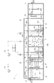
図1及び図2に示すように、本実施形態に係る浄化槽1は、上流側から固液分離槽A、嫌気ろ床槽B(嫌気処理槽の一例)、第1ろ過槽C1(ろ過槽の一例)、担体流動槽D(好気処理槽の一例)、第2ろ過槽C2、処理水槽E、及び消毒槽Fを備えて構成されている。
以下、本発明に係る浄化槽の一実施の形態について、図面に基づいて説明する。
図1及び図2に示すように、本実施形態に係る浄化槽1は、上流側から固液分離槽A、嫌気ろ床槽B(嫌気処理槽の一例)、第1ろ過槽C1(ろ過槽の一例)、担体流動槽D(好気処理槽の一例)、第2ろ過槽C2、処理水槽E、及び消毒槽Fを備えて構成されている。
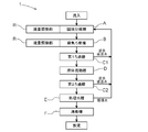
被処理水の原水は、原水流入口2から第1流入バッフル11を介して固液分離槽Aに流入し、嫌気ろ床槽B、第1ろ過槽C1、担体流動槽D、第2ろ過槽C2、処理水槽Eの順に下流へ移送されつつ分解処理され、消毒槽Fを経て放流口から槽外に放流される。
固液分離槽Aは、原水流入口2から流入した被処理水を受けて一時貯留する。これにより、被処理水中に含まれる大きな夾雑物、固形物、油脂等が重力沈降により分離されて、槽上部にスカムが貯留されると共に、槽底部に汚泥が貯留される。
固液分離槽Aで処理された被処理水は、第1移流口H1から嫌気ろ床槽Bへと流れる。第1移流口H1は、水面下に常時位置するように、固液分離槽Aと嫌気ろ床槽Bとを仕切る第1仕切壁W1の上下方向の中間位置に設けられている。尚、第1移流口H1は、第1仕切壁W1の嫌気ろ床槽Bの側に設けられている第2流入バッフル12に通じている。
嫌気ろ床槽Bには、嫌気性微生物を定着保持して育成できる嫌気ろ床3が設けられている。嫌気ろ床3の構成例としては、例えば網目状の濾材押さえ用板と網目状の濾材受け用板との間に複数の球状濾材を充填した構成などを挙げることができる。
嫌気ろ床槽Bでは、被処理水が嫌気ろ床3を通過する際に、その濾材の表面に付着した嫌気性微生物による有機物の嫌気分解が実施されると共に、固液分離槽Aで捕捉できなかった固形物が捕捉される。また嫌気ろ床槽Bでは、嫌気性微生物の働きにより酸化態窒素の脱窒反応も行われる。
尚、固液分離槽Aと嫌気ろ床槽Bは、LWL~HWLの範囲で流量を調節可能な流量調整部Rを備えており、朝夕の特定時間等に集中する被処理水量のピーク量を吸収する構成としてある。
嫌気ろ床槽Bで処理された被処理水は、流量調整用の第1エアリフトポンプP1によって第1ろ過槽C1に移送される。尚、第1エアリフトポンプP1は計量ボックス15を備えており、槽外に設置された第1ブロワ13から空気が供給される。また、嫌気ろ床槽Bと第1ろ過槽C1とを仕切る仕切壁に設けられたバッフル16の内側に第1エアリフトポンプP1の吸込み口が配置される。
第1ろ過槽C1には、複数のろ過担体からなる第1ろ過層4が形成されている。当該第1ろ過層4は複数のろ過担体を沈降堆積させた状態で形成してあることが望ましい。そのようなろ過担体の一例としては、例えば、比重約1.08、直径15mm、長さ15mmの中空円筒状担体が挙げられる。またろ過担体の素材としては、例えばポリプロピレン(PP)が挙げられる。尚、ろ過担体の形状、大きさ、素材については上記構成に限定されるものではなく、耐久性や処理性能がこれと同等以上と判断され得るような構成であればどのような構成であっても良い。
第1ろ過槽C1では、第1エアリフトポンプP1によって第1ろ過層4の上に供給された被処理水が下降流として第1ろ過層4を通過し、その際に被処理水中の浮遊物質(SS)が主として捕捉される。下降流のろ過処理においては、第1ろ過層4が複数のろ過担体を沈降堆積させた状態で形成してあることから、後段に設置される担体流動槽Dの直前までろ過処理を行うことができるため、第1ろ過槽C1に沈降した汚泥が担体流動槽Dへ流出する虞がなく、被処理水中に含まれる浮遊物質(SS)や汚泥をより確実に捕捉することができる。さらに、後述する返送装置の第2エアリフトポンプP2の吸込み口を第1ろ過層4の上方に設けることで、逆洗時にも浮遊物質(SS)や汚泥の担体流動槽Dへの流出を防止することができる。ろ過された被処理水は、第1ろ過槽C1と担体流動槽Dとを仕切る第2仕切壁W2の下部に設けられている第2移流口H2を介して担体流動槽Dに流れる。
担体流動槽Dは、微生物を担持した状態で被処理水と共に流動可能に構成してある複数の流動担体6を収容保持する。また担体流動槽Dの槽底部中央に散気管7が設けられており、槽外に設置された第2ブロワ14からの空気供給により、散気管7から気泡が放出されるよう構成されている。散気管7から気泡が放出されると、槽中央で上昇流及び槽側壁側で下降流が生じ、これにより流動担体6が槽内を旋回流動する。
担体流動槽Dでは、流動担体6に付着した微生物の働きにより有機物の好気分解及びアンモニア態窒素の硝化反応が行われる。流動担体6の一例としては、例えば、比重約1.01、大きさ20mm×20mmの角形スポンジ状担体が挙げられる。また流動担体6の素材としては、例えばポリウレタン(PU)が挙げられる。尚、流動担体6の形状、大きさ、素材については上記構成に限定されるものではなく、耐久性や処理性能が同等以上と判断され得るような構成であればどのような構成であっても良い。
担体流動槽Dで処理された被処理水は、担体流動槽Dと第2ろ過槽C2とを仕切る第3仕切壁W3の上部に設けられている第3移流口H3を介して、オーバーフローにより第2ろ過槽C2に流れる。
第2ろ過槽C2には、上述の第1ろ過槽C1と同様に、複数のろ過担体からなる第2ろ過層8が形成されている。当該第2ろ過層8は複数のろ過担体を沈降堆積させた状態で形成してあることが望ましい。そのようなろ過担体の一例としては、例えば、比重約1.08、直径15mm、長さ15mmの中空円筒状担体が挙げられる。またろ過担体の素材としては、例えばポリプロピレン(PP)が挙げられる。尚、ろ過担体の形状、大きさ、素材については上記構成に限定されるものではなく、耐久性や処理性能がこれと同等以上と判断され得るような構成であればどのような構成であっても良い。
第2ろ過槽C2では、第3移流口H3から第2ろ過層8の上に供給された被処理水が下降流として第2ろ過層8を通過し、その際に被処理水中の浮遊物質(SS)が主として捕捉される。ろ過された被処理水は、第2ろ過槽C2と処理水槽Eとを仕切る第4仕切壁W4の下部に設けられている第4移流口H4を介して処理水槽Eに流れる。
処理水槽Eは、第2ろ過槽C2で濾過した被処理水を一時的に貯留すると同時に、第2ろ過槽C2で捕捉できなかった剥離汚泥を分離し、汚泥の流出を防止する。また処理水槽Eには、循環用の第4エアリフトポンプP4が設けられており、貯留された被処理水の一部が固液分離槽Aに常時移送される。尚、第4エアリフトポンプP4には、槽外に設置された第2ブロワ14から空気が供給される。
処理水槽Eで処理された被処理水は、処理水槽Eと消毒槽Fとを仕切る第5仕切壁W5の上部に設けられている第5移流口H5を介して、オーバーフローにより消毒槽Fの消毒装置10に流れる。被処理水は、消毒装置10で消毒剤と接触して消毒された後、消毒槽Fに一時貯留されてから放流口より槽外に放流される。
第1ろ過槽C1には、その底部に第1逆洗管5(逆洗装置の一例)が設けられている。また第1ろ過槽C1には、被処理水返送用の第2エアリフトポンプP2(返送装置の一例)が設けられている。槽外に設置された第2ブロワ14から空気が供給され、第1逆洗管5から気泡が放出されると、第1ろ過層4のろ過担体に付着した汚泥が剥離し、第1ろ過層4の目詰まりを防止する。そして、剥離した汚泥を含む被処理水が、第2エアリフトポンプP2により固液分離槽Aに返送される。
第1逆洗管5による逆洗動作と、第2エアリフトポンプP2による返送動作とを制御する制御機構を設けるように構成しても良い。逆洗動作は、浄化槽への被処理水の流入が無いと考えられる時間帯に実施されることが望ましく、例えば、1日に3回以上(例えば午前2時、3時、4時に開始)で、1回あたり10分間程度で実施されるように制御されることが望ましい。返送動作は、逆洗時あるいは逆洗直後に実施されるように制御されることが望ましい。
また第2ろ過槽C2にも第1ろ過槽C1と同様に、第2逆洗管9と第3エアリフトポンプP3とが設けられている。槽外に設置された第2ブロワ14から空気が供給され、第2逆洗管9から気泡が放出されると、第2ろ過層8のろ過担体に付着した汚泥が剥離し、第2ろ過層8の目詰まりを防止する。そして、剥離した汚泥を含む被処理水が、第3エアリフトポンプP3により固液分離槽Aに返送される。
第2逆洗管9による逆洗動作と、第3エアリフトポンプP3による返送動作とを制御する制御機構を設けるように構成しても良い。逆洗動作は、浄化槽への被処理水の流入が無いと考えられる時間帯に実施されることが望ましく、例えば、1日に3回以上(例えば午前2時、3時、4時に開始)で、1回あたり10分間程度で実施されるように制御されることが望ましい。返送動作は、逆洗時あるいは逆洗直後に実施されるように制御されることが望ましい。
第1ろ過槽C1における逆洗・返送動作と、第2ろ過槽C2における逆洗・返送動作とが、同じタイミングで実施されるように制御される構成としても良い。
〔その他の実施形態〕
1.上述の第1ろ過槽C1及び第2ろ過槽C2のそれぞれにおける第1ろ過層4及び第2ろ過層8を、複数のろ過担体を浮揚させた状態で形成するように構成しても良い。
2.上述の第2及び第3エアリフトポンプP2,P3の返送先は、嫌気処理槽以上の上流槽であればよく、嫌気ろ床槽Bに返送したり、あるいは固液分離槽Aと嫌気ろ床槽Bの両方に返送する構成としても良い。
3.上述の実施形態では、第1ブロワ13及び第2ブロワ14の2台のブロワを使用する構成を示しているがこの構成に限定されるものではなく、1台のブロワで兼用するように構成しても良い。
1.上述の第1ろ過槽C1及び第2ろ過槽C2のそれぞれにおける第1ろ過層4及び第2ろ過層8を、複数のろ過担体を浮揚させた状態で形成するように構成しても良い。
2.上述の第2及び第3エアリフトポンプP2,P3の返送先は、嫌気処理槽以上の上流槽であればよく、嫌気ろ床槽Bに返送したり、あるいは固液分離槽Aと嫌気ろ床槽Bの両方に返送する構成としても良い。
3.上述の実施形態では、第1ブロワ13及び第2ブロワ14の2台のブロワを使用する構成を示しているがこの構成に限定されるものではなく、1台のブロワで兼用するように構成しても良い。
本発明に係る浄化槽は、小型の浄化槽だけでなく、中型及び大型の浄化槽に用いることもできる。
1 浄化槽
2 原水流入口
3 嫌気ろ床
4 第1ろ過層
5 第1逆洗管(逆洗装置)
6 流動担体
7 散気管
8 第2ろ過層
9 第2逆洗管
10 消毒装置
11 第1流入バッフル
12 第2流入バッフル
13 第1ブロワ
14 第2ブロワ
15 計量ボックス
16 バッフル
A 固液分離槽
B 嫌気ろ床槽(嫌気処理槽)
C1 第1ろ過槽(ろ過槽)
D 担体流動槽(好気処理槽)
C2 第2ろ過槽
E 処理水槽
F 消毒槽
R 流量調整部
P1 第1エアリフトポンプ
P2 第2エアリフトポンプ(返送装置)
P3 第3エアリフトポンプ
P4 第4エアリフトポンプ
H1~H5 第1~第5移流口
W1~W5 第1~第5仕切壁
Claims (5)
- 被処理水を嫌気処理する嫌気処理槽と、嫌気処理された被処理水を好気処理する好気処理槽とを備える浄化槽において、
ろ過層を形成してあるろ過槽を、前記嫌気処理槽と前記好気処理槽との間に設けてあることを特徴とする浄化槽。 - 前記ろ過槽から、前記嫌気処理槽以上の上流槽に被処理水を返送する返送装置を設けてあることを特徴とする請求項1に記載の浄化槽。
- 前記嫌気処理槽の上流に固液分離槽を備え、前記返送装置が該固液分離槽に被処理水を返送することを特徴とする請求項2に記載の浄化槽。
- 前記ろ過槽に逆洗装置を設けてあることを特徴とする請求項2又は3に記載の浄化槽。
- 前記ろ過層が、複数のろ過担体を沈降堆積させた状態で形成してあることを特徴とする請求項1~4のいずれか1項に記載の浄化槽。
Priority Applications (1)
| Application Number | Priority Date | Filing Date | Title |
|---|---|---|---|
| CN201680013128.9A CN107406287A (zh) | 2015-03-05 | 2016-02-19 | 净化槽 |
Applications Claiming Priority (2)
| Application Number | Priority Date | Filing Date | Title |
|---|---|---|---|
| JP2015043806A JP6632202B2 (ja) | 2015-03-05 | 2015-03-05 | 浄化槽 |
| JP2015-043806 | 2015-03-05 |
Publications (1)
| Publication Number | Publication Date |
|---|---|
| WO2016140084A1 true WO2016140084A1 (ja) | 2016-09-09 |
Family
ID=56843976
Family Applications (1)
| Application Number | Title | Priority Date | Filing Date |
|---|---|---|---|
| PCT/JP2016/054870 WO2016140084A1 (ja) | 2015-03-05 | 2016-02-19 | 浄化槽 |
Country Status (3)
| Country | Link |
|---|---|
| JP (1) | JP6632202B2 (ja) |
| CN (1) | CN107406287A (ja) |
| WO (1) | WO2016140084A1 (ja) |
Citations (6)
| Publication number | Priority date | Publication date | Assignee | Title |
|---|---|---|---|---|
| JPS425759Y1 (ja) * | 1964-02-24 | 1967-03-22 | ||
| JPH0322593U (ja) * | 1989-07-18 | 1991-03-08 | ||
| JPH07237Y2 (ja) * | 1989-04-11 | 1995-01-11 | 株式会社クボタ | 汚水処理装置 |
| JP2005205377A (ja) * | 2004-01-26 | 2005-08-04 | Fuji Clean Kogyo Kk | 汚水処理装置 |
| JP2008119562A (ja) * | 2006-11-08 | 2008-05-29 | Fuji Clean Kogyo Kk | 水処理装置及び水処理方法 |
| JP2009082847A (ja) * | 2007-10-01 | 2009-04-23 | Hitachi Housetec Co Ltd | 好気濾床槽及びこの好気濾床槽の運転方法 |
Family Cites Families (2)
| Publication number | Priority date | Publication date | Assignee | Title |
|---|---|---|---|---|
| JP4979614B2 (ja) * | 2008-02-27 | 2012-07-18 | 大阪瓦斯株式会社 | ディスポーザー排水の処理方法及び処理装置 |
| CN203878024U (zh) * | 2014-05-13 | 2014-10-15 | 杭州友源环保科技有限公司 | 一种养殖场废水处理系统 |
-
2015
- 2015-03-05 JP JP2015043806A patent/JP6632202B2/ja active Active
-
2016
- 2016-02-19 CN CN201680013128.9A patent/CN107406287A/zh active Pending
- 2016-02-19 WO PCT/JP2016/054870 patent/WO2016140084A1/ja active Application Filing
Patent Citations (6)
| Publication number | Priority date | Publication date | Assignee | Title |
|---|---|---|---|---|
| JPS425759Y1 (ja) * | 1964-02-24 | 1967-03-22 | ||
| JPH07237Y2 (ja) * | 1989-04-11 | 1995-01-11 | 株式会社クボタ | 汚水処理装置 |
| JPH0322593U (ja) * | 1989-07-18 | 1991-03-08 | ||
| JP2005205377A (ja) * | 2004-01-26 | 2005-08-04 | Fuji Clean Kogyo Kk | 汚水処理装置 |
| JP2008119562A (ja) * | 2006-11-08 | 2008-05-29 | Fuji Clean Kogyo Kk | 水処理装置及び水処理方法 |
| JP2009082847A (ja) * | 2007-10-01 | 2009-04-23 | Hitachi Housetec Co Ltd | 好気濾床槽及びこの好気濾床槽の運転方法 |
Also Published As
| Publication number | Publication date |
|---|---|
| CN107406287A (zh) | 2017-11-28 |
| JP6632202B2 (ja) | 2020-01-22 |
| JP2016159290A (ja) | 2016-09-05 |
Similar Documents
| Publication | Publication Date | Title |
|---|---|---|
| JP5945342B2 (ja) | 廃水の生物学的浄化のための方法及びリアクタ | |
| US20130168331A1 (en) | Means for Cleaning Packed Media In a Wastewater Filter Treatment System | |
| KR101767032B1 (ko) | 낙농업용 세정수 정화장치 | |
| JP2010247051A (ja) | 水処理装置 | |
| JP5048708B2 (ja) | 浄化槽 | |
| JP2007117908A (ja) | 浄化槽 | |
| JP4979531B2 (ja) | 好気濾床槽及びこの好気濾床槽の運転方法 | |
| JP3963667B2 (ja) | 汚水処理装置及びその運転方法 | |
| JP4090218B2 (ja) | 汚水処理装置及びその運転方法 | |
| WO2016140084A1 (ja) | 浄化槽 | |
| JP2007038096A (ja) | 剥離汚泥分離装置および汚水浄化槽 | |
| JP2016159290A5 (ja) | ||
| KR20080082852A (ko) | 오폐수 처리용 침전 장치 및 이를 이용한 오폐수 처리 방법 | |
| JP4100873B2 (ja) | 汚水処理装置 | |
| JP3970612B2 (ja) | 浄化処理装置および浄化処理方法 | |
| WO2020031684A1 (ja) | 浄化槽 | |
| JP4346985B2 (ja) | 中水装置、排水処理装置 | |
| JP4865997B2 (ja) | 汚水処理装置の運転方法及び汚水処理装置 | |
| WO2012133739A1 (ja) | 汚水浄化設備 | |
| JP2003181483A (ja) | 浄化槽の処理方法及びその浄化槽 | |
| JP3977122B2 (ja) | 排水処理装置および排水処理装置におけるエアー供給方法 | |
| JP2004358411A (ja) | 活性汚泥処理システム用膜分離ユニット | |
| JPH105787A (ja) | 流動床式生物処理装置及び方法 | |
| JP2000325977A (ja) | 浄化槽及びその運転方法 | |
| JP2004305928A (ja) | 担体流動生物濾過廃水処理装置 |
Legal Events
| Date | Code | Title | Description |
|---|---|---|---|
| 121 | Ep: the epo has been informed by wipo that ep was designated in this application |
Ref document number: 16758778 Country of ref document: EP Kind code of ref document: A1 |
|
| NENP | Non-entry into the national phase |
Ref country code: DE |
|
| 122 | Ep: pct application non-entry in european phase |
Ref document number: 16758778 Country of ref document: EP Kind code of ref document: A1 |