WO2016139743A1 - チップコンベア - Google Patents
チップコンベア Download PDFInfo
- Publication number
- WO2016139743A1 WO2016139743A1 PCT/JP2015/056163 JP2015056163W WO2016139743A1 WO 2016139743 A1 WO2016139743 A1 WO 2016139743A1 JP 2015056163 W JP2015056163 W JP 2015056163W WO 2016139743 A1 WO2016139743 A1 WO 2016139743A1
- Authority
- WO
- WIPO (PCT)
- Prior art keywords
- conveyor
- cutting fluid
- chips
- chip conveyor
- chip
- Prior art date
- Legal status (The legal status is an assumption and is not a legal conclusion. Google has not performed a legal analysis and makes no representation as to the accuracy of the status listed.)
- Ceased
Links
Images


Classifications
-
- B—PERFORMING OPERATIONS; TRANSPORTING
- B23—MACHINE TOOLS; METAL-WORKING NOT OTHERWISE PROVIDED FOR
- B23Q—DETAILS, COMPONENTS, OR ACCESSORIES FOR MACHINE TOOLS, e.g. ARRANGEMENTS FOR COPYING OR CONTROLLING; MACHINE TOOLS IN GENERAL CHARACTERISED BY THE CONSTRUCTION OF PARTICULAR DETAILS OR COMPONENTS; COMBINATIONS OR ASSOCIATIONS OF METAL-WORKING MACHINES, NOT DIRECTED TO A PARTICULAR RESULT
- B23Q11/00—Accessories fitted to machine tools for keeping tools or parts of the machine in good working condition or for cooling work; Safety devices specially combined with or arranged in, or specially adapted for use in connection with, machine tools
- B23Q11/0042—Devices for removing chips
- B23Q11/0057—Devices for removing chips outside the working area
-
- B—PERFORMING OPERATIONS; TRANSPORTING
- B23—MACHINE TOOLS; METAL-WORKING NOT OTHERWISE PROVIDED FOR
- B23Q—DETAILS, COMPONENTS, OR ACCESSORIES FOR MACHINE TOOLS, e.g. ARRANGEMENTS FOR COPYING OR CONTROLLING; MACHINE TOOLS IN GENERAL CHARACTERISED BY THE CONSTRUCTION OF PARTICULAR DETAILS OR COMPONENTS; COMBINATIONS OR ASSOCIATIONS OF METAL-WORKING MACHINES, NOT DIRECTED TO A PARTICULAR RESULT
- B23Q11/00—Accessories fitted to machine tools for keeping tools or parts of the machine in good working condition or for cooling work; Safety devices specially combined with or arranged in, or specially adapted for use in connection with, machine tools
- B23Q11/0042—Devices for removing chips
- B23Q11/0067—Devices for removing chips chip containers located under a machine or under a chip conveyor
-
- B—PERFORMING OPERATIONS; TRANSPORTING
- B65—CONVEYING; PACKING; STORING; HANDLING THIN OR FILAMENTARY MATERIAL
- B65G—TRANSPORT OR STORAGE DEVICES, e.g. CONVEYORS FOR LOADING OR TIPPING, SHOP CONVEYOR SYSTEMS OR PNEUMATIC TUBE CONVEYORS
- B65G17/00—Conveyors having an endless traction element, e.g. a chain, transmitting movement to a continuous or substantially-continuous load-carrying surface or to a series of individual load-carriers; Endless-chain conveyors in which the chains form the load-carrying surface
- B65G17/06—Conveyors having an endless traction element, e.g. a chain, transmitting movement to a continuous or substantially-continuous load-carrying surface or to a series of individual load-carriers; Endless-chain conveyors in which the chains form the load-carrying surface having a load-carrying surface formed by a series of interconnected, e.g. longitudinal, links, plates, or platforms
- B65G17/065—Conveyors having an endless traction element, e.g. a chain, transmitting movement to a continuous or substantially-continuous load-carrying surface or to a series of individual load-carriers; Endless-chain conveyors in which the chains form the load-carrying surface having a load-carrying surface formed by a series of interconnected, e.g. longitudinal, links, plates, or platforms the load carrying surface being formed by plates or platforms attached to a single traction element
-
- B—PERFORMING OPERATIONS; TRANSPORTING
- B65—CONVEYING; PACKING; STORING; HANDLING THIN OR FILAMENTARY MATERIAL
- B65G—TRANSPORT OR STORAGE DEVICES, e.g. CONVEYORS FOR LOADING OR TIPPING, SHOP CONVEYOR SYSTEMS OR PNEUMATIC TUBE CONVEYORS
- B65G17/00—Conveyors having an endless traction element, e.g. a chain, transmitting movement to a continuous or substantially-continuous load-carrying surface or to a series of individual load-carriers; Endless-chain conveyors in which the chains form the load-carrying surface
- B65G17/30—Details; Auxiliary devices
- B65G17/32—Individual load-carriers
- B65G17/34—Individual load-carriers having flat surfaces, e.g. platforms, grids, forks
-
- B—PERFORMING OPERATIONS; TRANSPORTING
- B65—CONVEYING; PACKING; STORING; HANDLING THIN OR FILAMENTARY MATERIAL
- B65G—TRANSPORT OR STORAGE DEVICES, e.g. CONVEYORS FOR LOADING OR TIPPING, SHOP CONVEYOR SYSTEMS OR PNEUMATIC TUBE CONVEYORS
- B65G19/00—Conveyors comprising an impeller or a series of impellers carried by an endless traction element and arranged to move articles or materials over a supporting surface or underlying material, e.g. endless scraper conveyors
- B65G19/18—Details
- B65G19/20—Traction chains, ropes, or cables
- B65G19/205—Traction chains, ropes, or cables for article conveyors, e.g. for container conveyors
Definitions
- This invention relates to the chip conveyor which has the structure for reducing the discharge
- a chip conveyor is provided for discharging the chips from the processing unit to the outside of the machine tool.
- the chip conveyor is configured such that a chip receiver and a storage tank are disposed below a processing portion where chips and cutting fluid fall, and an endless hinge belt extending obliquely upward from the tank moves around. Therefore, the chips that fall from the chip receiver into the storage tank are carried out by periodically driving the chip conveyor. At that time, the chips are conveyed from the storage tank so as to rise through the climbing portion, and dropped from the rising portion to the collection box and collected.
- Some chip conveyors are provided with scrapers at a predetermined interval with respect to the hinge belt so that chips can be efficiently conveyed.
- the chip conveyor of a machine tool has a problem that the cutting fluid adhering to the chips is discharged together with the chips to a collection box. That is, the cutting fluid that is normally filtered and repeatedly used is discharged as the chips are collected, and the amount gradually decreases. Such a problem is particularly remarkable in a chip conveyor having a scraper. Therefore, in Patent Document 1 below, a configuration is provided in which chips are collected through a horizontal portion provided at the upper end, and the cutting fluid is dropped from the gap of the hinge plate and can be collected through a ridge. ing. Moreover, in the following patent document 2, a shooter provided with a porous plate and a dam plate is provided in addition to the chip conveyor, and a scissors for collecting the cutting fluid dropped through the hole of the porous plate is provided. .
- an object of the present invention is to provide a chip conveyor that reduces the discharge amount of the cutting fluid with a simple configuration in order to solve such a problem.
- the chip conveyor in one aspect of the present invention connects a storage tank in which chips and cutting fluid are stored, and both longitudinal ends of a large number of hinge plates by hinges, and passes through an ascending portion from the storage tank by a drive mechanism.
- An endless conveyor body that circulates and a control device that controls the drive of the drive mechanism, and a scraper plate formed in a standing state with respect to the hinge plate is provided in the traveling direction in the conveyor body.
- a plurality of the scrapers are arranged along the width direction of the conveyor body, and have one or more through portions through which cutting fluid passes within the width interval. is there.
- the cutting fluid slips through the through hole to the rear side in the traveling direction, so that a lot of cutting fluid is pumped out from the storage tank as in the past. Can be avoided. Further, the cutting fluid still remaining on the scraper flows down through the through-hole and returns to the storage tank when moving the climbing portion. Therefore, in the present invention, the amount of cutting fluid discharged can be reduced, and this can be achieved with a simple configuration relating to the scraper.
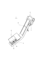
- FIG. 1 is a perspective view showing the whole chip conveyor of the first embodiment
- FIG. 2 is a side view showing the internal structure in a simplified manner.
- the chip conveyor 1 is mounted on a machine tool such as a lathe. For example, in a machine tool, rotation is given to a work held by a spindle chuck, and a predetermined cutting process is performed by a cutting tool mounted on a tool post.
- the chip conveyor 1 is incorporated in such a machine tool. Therefore, the chip conveyor 1 is provided with a chip receiver 2 and a storage tank 3 for storing chips and cutting fluid (coolant) so as to be positioned below the processing portion.
- the cutting fluid ejected at the time of machining is once stored in the storage tank 3, filtered through a filtering device, and then supplied to the processing unit again.
- the chips stored in the storage tank 3 are transported by driving the chip conveyor 1 and put into a collection box.
- a certain amount of the cutting fluid is discharged to the outside as the chips are discharged. Therefore, if the total amount of the cutting fluid circulating in the machine tool has decreased, it must be replenished with a new cutting fluid. Costs also increase.
- the chip conveyor 1 of this embodiment reduces the discharge amount of the cutting fluid accompanying chip collection, and reduces the replenishment frequency and replenishment amount of a cutting fluid.
- the chip conveyor 1 is formed with a transport duct 5 that rises obliquely upward from the storage tank 3.
- the transport duct 5 extends obliquely upward from the storage tank 3 toward the rear side of the machine tool, and a discharge duct 6 is provided at the upper end of the transport duct 5.
- the discharge duct 6 has a bent shape so as to continue from the transport duct 5 to a discharge port opened downward.
- a recovery box 100 for recovering the discharged chips is arranged below the discharge duct 6.
- the storage tank 3, the conveyance duct 5, and the discharge duct 6 which comprise the chip conveyor 1 were formed so that the continuous space might be formed in the inside, and the endless hinge belt 10 might circulate in it.
- a conveyor body is configured.
- a pair of left and right drive sprockets 11 are pivotally supported inside the discharge duct 6, and a pair of left and right driven sprockets 12 are pivotally supported in the storage tank 3 at the end position far from the discharge duct 6.
- An endless conveyor chain 13 (see FIG. 3) is stretched between the drive sprocket 11 and the driven sprocket 12, and the hinge belt 10 is configured integrally with the conveyor chain 13.
- a drive motor 7 that outputs rotation is installed outside the discharge duct 6.
- the hinge belt 10 is configured such that the drive sprocket 11 and the driven sprocket 12 are turned back and move around vertically. That is, the hinge belt 10 is formed with an outward path and a return path that move in positions where the sprockets 11 and 12 overlap each other when viewed in the vertical direction, the upper side is an outward path for discharging and conveying chips, and the lower side is after discharging chips. It has become a return path. Then, the chips collected in the storage tank 3 are discharged and conveyed by driving the drive motor 7, but in this embodiment, the hinge belt 10 is used so that the chips can be efficiently conveyed. A scraper plate 18 is formed.
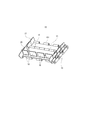
- FIG. 3 is a perspective view showing a part of the hinge belt.
- the hinge belt 10 has a plurality of hinge plates 15 connected by hinges 16. That is, the hinge pin is connected to the conveyor chain 13, and the two hinge plates 15 arranged in the front-rear direction are connected to each cylindrical portion 151 through the common hinge pin.
- a plurality of hinge plates 15 connected in this way are continuous in a circumferential shape.
- the hinge belt 10 has a plurality of side plates 17 disposed at both ends in the left-right width direction of the hinge plate 15 so that chips do not spill from the side.
- a conveyor chain 13 is disposed outside the side plate 17.
- a scraping plate 18 is integrally formed with a part of the hinge plate 15.
- the hinge plate 15 is a rectangular plate material, and a cylindrical portion 151 through which a hinge pin is passed is formed on the long side portion in the front-rear direction.
- the scraper plate 18 is a rectangular plate member whose corners are chamfered, and is joined to the hinge plate 15 so as to be abutted in the orthogonal direction. The joining state is parallel to the hinge 16 and orthogonal to the traveling direction of the hinge belt 10.
- the scraper 18 in a standing posture is a stop member that is formed at substantially the same height as the side plate 17 and prevents chips from slipping down even at the climbing portion in the transport duct 5.
- a plurality of scraping plates 18 are provided in the circumferential direction on the hinge belt 10 and are arranged at regular intervals. Therefore, the chips in the storage tank 3 are conveyed by the amount sandwiched between the front and rear scraping plates 18. Therefore, the distance between the scraping plates 18 positioned forward and backward when viewed in the traveling direction of the hinge belt 10 is such that, for example, when the climbing portion in the transport duct 5 is lifted, the one piece of chips distributed by the scraping plate 18 is in the traveling direction. It is set to the extent that it does not fall out to the rear side.
- the scraper plate of the hinge belt can efficiently transport the chips, but the cutting fluid present in the tank is scraped off when the chips are discharged. Therefore, in the present embodiment, the plurality of through portions 20 are formed in the width direction of the hinge belt 10 so that the cutting fluid is difficult to be taken out from the storage tank 3 and the cutting fluid is likely to flow down at the climbed portion.
- the scraper is originally formed in a size that matches the width of the hinge belt, but in this embodiment, the small rectangular scraper 18 has a constant interval in the width direction so that the threading portion 20 can be formed. Is arranged in.
- the size and number of the through-holes 20 are not particularly limited, and may be designed in consideration of the shape and size of chips, or the amount of cutting fluid accumulated by the scraper 18. Further, the shape of the through portion 20 is also free, and is not a slit shape in which the scraping plates 18 are separated from each other as shown in the figure, but the hinge plate 15 and the scraping plate that are matched to the width of the hinge belt 10. It may be a rectangular shape or a semicircular hole formed on the joint side.
- the chips in the storage tank 3 are carried out by the circular movement of the hinge belt 10.
- the cutting fluid in the storage tank 3 slips through the passing portion 20 of the scraping plate 18 that advances.
- chips are supported by the scraping plate 18, and rise according to the circular movement of the hinge belt 10 without sliding down.
- the cutting fluid flows down through the through portion 20 of the scraper 18.
- the through portion 20 is formed in the scraper plate 18, it is difficult for the cutting fluid to remain on the scraper plate 18 when the chips are discharged, and it is easy to flow down from the scraper plate 18 at the climbing portion.
- the drive control of the chip conveyor 1 made it easy for a cutting fluid to flow down may be performed.
- the chip conveyor 1 is rotated by the drive sprocket 11 by the output of the drive motor 7, and moves up and down at the turn-back location of the drive sprocket 11 and the driven sprocket 12.
- the drive motor 7 is connected to a power supply device 8 that supplies drive power
- the power supply device 8 is connected to a control device 9.
- the control device 9 is for controlling the drive of a machine tool such as a drive motor of each drive unit such as a main shaft and a cutting fluid supply device, and stores a conveyor control program for the chip conveyor 1 therein.
- the machining time information for the workpiece is acquired from the rotation control of the spindle, and it is determined from the machining time that an appropriate amount of chips has accumulated in the storage tank 3, and the drive motor 7 is driven. Chips are discharged and conveyed by the conveyor 1.
- the driving of the chip conveyor 1 is classified into a standby operation until a predetermined amount of chips is stored in the storage tank 3 and a transport operation for discharging chips.
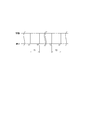
- intermittent operation as shown in the time chart of FIG. 4 is performed in the transport operation.
- This intermittent operation is performed when chips are transported through the climbing portion in the transport duct 5, and the stop for a predetermined time T1 is repeated at regular intervals.
- This is for making the time until the chips carried out from the storage tank 3 reach the discharge duct 6 longer. That is, the cutting fluid adheres to the chips carried out from the storage tank 3, but more cutting fluid falls from the chips due to a longer conveying time. Further, a larger amount of the cutting fluid remaining on the scraper 18 also flows down from the through portion 20.
- the stop time T1 is about several seconds, and the number of stops until the chips reach the discharge duct 6 is about several times.
- the intermittent operation is performed a plurality of times within a short time interval. This intermittent operation is performed, for example, at the end of the stop time T1 shown in FIG. 4 (t2, t4, etc.). Therefore, the chip conveyor 1 is intermittently operated by repeating the movement and the stop several times during the time T2 when the circular movement of the hinge belt 10 is resumed. Thereafter, the circular movement of the hinge belt 10 at a constant speed is continued until the next stop.
- Such an intermittent operation gives vibration to the hinge belt 10, and the remaining cutting fluid adhering to the chips is also shaken off.
- the cutting fluid accumulated in the scraper plate 18 is also caused to flow downward from the through portion 20 due to the vibration of intermittent operation. That is, the scraping plate 18 collects the cutting fluid scraped from the storage tank 3 and the cutting fluid dropped from the chips. Such cutting fluid flows down from the through portion 20 even during normal conveyance, but still remains on the scraper 18 to some extent.
- the vibration of intermittent operation is also intended to drop as much of the remaining cutting fluid as possible. This point is effective not only for the scraping plate 18 but also for the cutting fluid that has accumulated on the raised portion of the hinge 16, so that the cutting fluid flows in that portion.
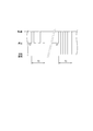
- the intermittent operation at the time T2 shown in FIG. 5 is not limited to the end of the stop time T1 shown in FIG. 4 (t2, t4, etc.), but at the start of the stop time T (t1, t3, etc.) It may be an arbitrary time during the time T1 or an arbitrary time other than the stop time T1. That is, it is only necessary to select and execute a timing at which more cutting fluid is shaken off from the chips and more cutting fluid flows from the through hole 20 of the scraper 18. Further, the intermittent operation may be such that the forward and backward movements of the hinge belt 10 (forward rotation and reverse rotation of the drive motor 7) are repeated as shown in the time chart of time T3 in FIG. The timing of this intermittent operation is the same as that of the intermittent operation at time T2.
- the cutting fluid slips through the through hole 20 to the rear side in the traveling direction, and thus from the storage tank 3 as in the past. It can be avoided that a lot of cutting fluid is pumped out. Still, the cutting fluid remaining on the scraper 18 flows down through the through hole 20 when moving the climbing portion in the transport duct 5. Thus, in the present embodiment, the cutting fluid is less likely to remain on the scraper 18 from the through portion 20. Therefore, until the scraper 18 reaches the discharge duct 6, a large amount of cutting fluid flows down and returns from the transport duct 5 to the storage tank 3, and the amount of cutting fluid discharged is reduced as compared with the conventional chip conveyor. To reduce waste. In addition, the effect can be obtained by the through portion 20 of the scraper plate 18 without a complicated structure.
- the intermittent operation is performed in the control of the chip conveyor 1, the cutting fluid adhering before the chips reach the discharge duct 6 and are put into the collection box 100 is removed. More falls from the chips. Then, the cutting fluid that has fallen away from the chips flows down to the storage tank 3 through the through hole 20 as described above. Further, since the intermittent operation is performed in the control of the chip conveyor 1, the adhering cutting fluid is shaken off more by the vibration of the hinge belt 10. Further, when the hinge belt 10 vibrates, the cutting fluid accumulated in the scraper plate 18 easily flows down from the through portion 20, and more cutting fluid is returned to the storage tank 3. Therefore, the amount of cutting fluid discharged can be reduced and waste can be reduced by controlling intermittent operation and intermittent operation for the chip conveyor 1 as compared with the conventional chip conveyor. In addition, the effect can be obtained by controlling the driving of the chip conveyor 1 without using a complicated structure.
- the chip conveyor 1 of the present embodiment can achieve the effect by a simple configuration such as the scraper 18 as described above, and thus the overall configuration can be simplified. That is, the cutting fluid that has fallen from the hinge belt 10 during conveyance flows through the conveyance duct 5 and is returned to the storage tank 3, and the storage portion of the cutting fluid is sufficient only by the storage tank 3.
- a tank is provided on the back portion where the recovery box is provided, and in the example of Patent Document 2, a bag for collecting cutting oil is separately provided on the back portion.
- the entire configuration of the chip conveyor 1 can be simplified as compared with such a conventional example.
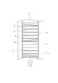
- FIG. 6 is a plan view schematically showing the hinge belt in the transport duct 5 of the chip conveyor.
- the chip conveyor 31 of this embodiment has the same configuration as the chip conveyor 1 of the first embodiment except for the scraper plate 33 provided on the hinge belt 32. Therefore, common configurations will be described with the same reference numerals.
- the hinge belt 32 is configured such that a plurality of hinge plates 15 are connected in a circumferential shape by hinges 16 and can be moved around by a drive motor.
- a scraper plate 33 is joined to the hinge plates 15 at regular intervals.
- a pair of left and right scrapers 33 are joined to one hinge plate 15.
- the scraper plate 33 is a rectangular plate material and is joined to the hinge plate 15 so as to be orthogonal. However, in this embodiment, it inclines to the rear side of the advancing direction toward the center from both left and right ends.
- Such a pair of left and right scrapers 33 are arranged apart from each other so that a gap is formed in the central portion, and a passage portion 35 is formed to allow the cutting fluid to flow down.
- the scraper 33 is set with an inclination angle capable of supporting chips at the climbing portion, and the size of the through portion 35 is not particularly limited, and is designed in consideration of the shape and size of the chips.
- chips in the storage tank 3 are carried out by the circular movement of the hinge belt 32.
- the cutting fluid in the storage tank 3 passes through the passing portion 35 of the scraping plate 33 that advances.
- the chips are supported by the scraper plate 33, and ascend according to the circular movement of the hinge belt 10 without sliding down.
- the cutting fluid flows down through the through portion 35 without staying at the inclined scraping plate 33.
- the chip conveyor 31 of the present embodiment even if the scraper plate 33 is provided on the hinge belt 32, the cutting fluid slips through the inclined through hole 35 to the rear side in the traveling direction. It can be avoided that a large amount of cutting fluid is pumped from the storage tank 3. Further, the cutting fluid remaining at the place where it has left the storage tank 3 flows along the inclined scraping plate 33 and flows down from the through portion 35. Therefore, according to the present embodiment, a large amount of cutting fluid is returned to the storage tank 3, and the amount of cutting fluid discharged can be reduced as compared with the conventional chip conveyor, and waste can be suppressed. In addition, the effect can be obtained by the through portion 35 of the inclined scraping plate 33 without using a complicated structure.
- the chip conveyor 31 of the present embodiment also performs intermittent operation and intermittent operation as in the first embodiment.
- the effect of the same operation can be obtained, and the discharge amount of the cutting fluid can be further reduced in combination with the configuration of the inclined scraping plate 33. And such an effect is acquired by drive control of chip conveyor 31, without making it a complicated structure.
- FIG. 7 is a plan view showing a simplified hinge belt in the transport duct 5 of the chip conveyor.
- the chip conveyor 41 of this embodiment also has the same configuration as the chip conveyor 1 of the first embodiment except for the scraper plate 43 provided on the hinge belt 42. Therefore, common configurations will be described with the same reference numerals.
- the hinge belt 42 is configured such that a plurality of hinge plates 15 are connected in a circumferential shape by the hinges 16 and can be moved around by a drive motor.
- a scraper plate 43 is joined to the hinge plates 15 at regular intervals.
- the scraper plate 43 is a rectangular plate material, is joined so as to be orthogonal to the hinge plate 15, and is inclined in the front-rear direction as viewed in the traveling direction in this embodiment.
- all the scraping plates 43 on the hinge belt 42 are tilted in one lateral direction, and when viewed in the traveling direction, the tilt directions are alternately reversed left and right.
- the rear end 431 due to the inclination of the scraper plate 43 is provided with a gap between the side plate 17 and a passage 45 is formed for the cutting fluid to flow down.
- the scraper plate 43 is set with an inclination angle capable of supporting chips at the climbing portion, and the size of the through portion 45 is not particularly limited, and is designed in consideration of the shape and size of the chips.
- the chip conveyor 41 carries the chips in the storage tank 3 by the circular movement of the hinge belt 42. At that time, the cutting fluid in the storage tank 3 passes through the passing portion 45 of the inclined scraping plate 43 that advances. And in the climbing part in the conveyance duct 5, chips are supported by the scraper plate 43, and ascend according to the circular movement of the hinge belt 10 without sliding down. On the other hand, the cutting fluid flows along the inclined scraping plate 43 and flows down through the through portion 45. Further, even if chips spill from the through portion 45 to the rear side in the traveling direction, the front and rear through portions 45 are alternately positioned on the left and right sides, so that chip removal is not caused only on the left and right sides.
- the chip conveyor 41 of the present embodiment even if the scraper plate 43 is provided on the hinge belt 42, the cutting fluid slips through the through hole 45 to the rear side in the traveling direction, so that the storage tank 3 is conventionally used. Therefore, it is possible to avoid a lot of cutting fluid being pumped out. Further, the cutting fluid remaining after leaving the storage tank 3 flows along the inclined scraping plate 43 and flows down from the through portion 45. Therefore, according to the present embodiment, a large amount of cutting fluid is returned to the storage tank 3, and the amount of cutting fluid discharged can be reduced as compared with the conventional chip conveyor, and waste can be suppressed. In addition, the effect can be obtained by the through portion 45 of the inclined scraping plate 43 without using a complicated structure.
- the chip conveyor 41 of the present embodiment also performs intermittent operation and intermittent operation as in the first embodiment.
- the effect of the same operation can be obtained, and the discharge amount of the cutting fluid can be further reduced in combination with the configuration of the inclined scraping plate 43. And such an effect is acquired by drive control of chip conveyor 41, without making it a complicated structure.
- the through portions 20 and 35 are formed so as to leave a gap in the width direction with respect to the plurality of scrapers 18 and 33 joined to the same hinge plate 15.
- the end portions of the scraping plates 18 or the scraping plates 33 are arranged so as to be separated from each other in the traveling direction of the hinge belts 10 and 32, and a gap between the end portions located in the front and rear is provided. It may be a threading part.
- the scraper plate 18 of the first embodiment may be inclined in the same direction as in the third embodiment.
- control which used the intermittent operation shown in FIG. 4 and the intermittent operation shown in FIG. 5 together was shown, control of only any one may be sufficient.
Landscapes
- Engineering & Computer Science (AREA)
- Mechanical Engineering (AREA)
- Auxiliary Devices For Machine Tools (AREA)
Abstract
Description
前記第1及び第2実施形態では、同じヒンジプレート15に接合された複数の掻き板18,33に対し、幅方向に隙間が空くようにして通し部20,35が形成されている。この点について、例えば、掻き板18同士或いは掻き板33同士の端部が、ヒンジベルト10,32の進行方向に見て前後に離れるようにして配置され、前後に位置する当該端部の隙間を通し部としてもよい。その場合、第1実施形態の掻き板18を、第3実施形態のように同方向に傾けるようにすることも考えられる。
また、前記実施形態では、図4に示す間欠運転と図5に示す断続運転とを併用した制御を示したが、いずれか一方のみの制御であってもよい。
Claims (6)
- 切屑及び切削液が貯留される貯留タンクと、多数のヒンジプレートの前後方向両端部をヒンジにより連結し、駆動機構により前記貯留タンク内から登り部分を通って周回移動する無端状のコンベア本体と、前記駆動機構の駆動を制御する制御装置とを有し、
前記コンベア本体には、前記ヒンジプレートに対して起立した状態で形成された掻き板が進行方向に間隔をあけて複数配置されたチップコンベアにおいて、
前記掻き板は、前記コンベア本体の幅方向に沿って形成され、その幅間隔内に切削液が通る一又は二以上の通し部を有するものであることを特徴とするチップコンベア。 - 前記掻き板は、前記コンベア本体の幅方向に傾斜して形成され、その傾斜によって進行方向後側に位置する端部に、幅方向に形成された前記通し部を有するものであることを特徴とする請求項1に記載のチップコンベア。
- 前記掻き板は、前記コンベア本体の幅方向中央に向けて左右両側から傾斜し、その中央部分に前記通し部が形成されたものであることを特徴とする請求項2に記載のチップコンベア。
- 前記掻き板は、前記コンベア本体の幅方向の一方に傾斜したものであり、前記コンベア本体の進行方向に並んだ複数の掻き板の前記傾斜方向が、一定であること又は交互に異なることを特徴とする請求項2に記載のチップコンベア。
- 前記制御装置は、前記駆動機構に対する駆動制御により、前記掻き板に支えられて切屑が前記登り部分を上昇する際、前記コンベア本体の進行を一定時間停止させる停止運転を行うものであることを特徴とする請求項1乃至請求項4のいずれかに記載のチップコンベア。
- 前記制御装置は、前記駆動機構に対する駆動制御により、前記掻き板に支えられて切屑が前記登り部分を上昇する際、前記コンベア本体の進行について一定時間だけ所定の間隔で駆動と停止とを繰り返す断続運転または、駆動と反転駆動とを繰り返す断続運転を行うものであることを特徴とする請求項1乃至請求項5のいずれかに記載のチップコンベア。
Priority Applications (3)
| Application Number | Priority Date | Filing Date | Title |
|---|---|---|---|
| PCT/JP2015/056163 WO2016139743A1 (ja) | 2015-03-03 | 2015-03-03 | チップコンベア |
| US15/554,011 US10105806B2 (en) | 2015-03-03 | 2015-03-03 | Chip conveyor |
| JP2017503246A JP6514765B2 (ja) | 2015-03-03 | 2015-03-03 | チップコンベア |
Applications Claiming Priority (1)
| Application Number | Priority Date | Filing Date | Title |
|---|---|---|---|
| PCT/JP2015/056163 WO2016139743A1 (ja) | 2015-03-03 | 2015-03-03 | チップコンベア |
Publications (1)
| Publication Number | Publication Date |
|---|---|
| WO2016139743A1 true WO2016139743A1 (ja) | 2016-09-09 |
Family
ID=56848380
Family Applications (1)
| Application Number | Title | Priority Date | Filing Date |
|---|---|---|---|
| PCT/JP2015/056163 Ceased WO2016139743A1 (ja) | 2015-03-03 | 2015-03-03 | チップコンベア |
Country Status (3)
| Country | Link |
|---|---|
| US (1) | US10105806B2 (ja) |
| JP (1) | JP6514765B2 (ja) |
| WO (1) | WO2016139743A1 (ja) |
Cited By (6)
| Publication number | Priority date | Publication date | Assignee | Title |
|---|---|---|---|---|
| CN106705575A (zh) * | 2016-12-21 | 2017-05-24 | 上海永太汽车零部件厂 | 零配件滤油装置 |
| CN107139011A (zh) * | 2017-06-29 | 2017-09-08 | 黄石鑫华轮毂有限公司 | 数控车床排屑装置 |
| JP2020021447A (ja) * | 2018-07-20 | 2020-02-06 | ファナック株式会社 | ワークの後処理方法、加工システムおよび管理システム |
| US11352221B2 (en) | 2018-07-20 | 2022-06-07 | Fanuc Corporation | Post-processing method for workpiece, machining system, and management system |
| JP2022106436A (ja) * | 2021-01-07 | 2022-07-20 | Dmg森精機株式会社 | 工作機械、工作機械の制御方法、および工作機械の制御プログラム |
| CN119347451A (zh) * | 2024-12-26 | 2025-01-24 | 常州市航铁机械有限公司 | 一种铁路装备传动轴内螺纹的成型去屑加工装置 |
Families Citing this family (5)
| Publication number | Priority date | Publication date | Assignee | Title |
|---|---|---|---|---|
| US10350719B2 (en) * | 2015-06-02 | 2019-07-16 | Samheung Precision Co. Ltd. | Device for discharging chips |
| JP6375424B1 (ja) * | 2017-09-13 | 2018-08-15 | 株式会社ブンリ | 濾過装置 |
| CN108311887A (zh) * | 2018-04-04 | 2018-07-24 | 罗威斯数控科技(昆山)有限公司 | 汽车行李架杆加工中心 |
| CN112963518B (zh) * | 2021-02-05 | 2025-09-23 | 青岛正大正电力环保设备有限公司 | 一种链轮及拖动机构 |
| CN114310459B (zh) * | 2022-03-15 | 2022-07-15 | 杭州吉宝传动设备有限公司 | 数控机床的强磁自动排屑系统及其防堵检测方法 |
Citations (4)
| Publication number | Priority date | Publication date | Assignee | Title |
|---|---|---|---|---|
| JPS62184951U (ja) * | 1986-05-14 | 1987-11-25 | ||
| JPH11254265A (ja) * | 1998-03-12 | 1999-09-21 | Nissan Diesel Motor Co Ltd | 切粉掻き上げ装置 |
| JP2003145390A (ja) * | 2001-11-14 | 2003-05-20 | Tsubakimoto Meifuran Kk | 濾過装置を備えた切粉搬出コンベヤ装置 |
| CN101786252A (zh) * | 2010-03-04 | 2010-07-28 | 沈阳华邦通用机械技术开发有限公司 | 全功能机床自动排屑机 |
Family Cites Families (7)
| Publication number | Priority date | Publication date | Assignee | Title |
|---|---|---|---|---|
| US5167839A (en) * | 1991-07-23 | 1992-12-01 | H & W Systems Corporation | Fluid coolant cleaning system for machine tool applications |
| JPH09150342A (ja) | 1995-11-30 | 1997-06-10 | Suzuki Motor Corp | 切削油の分離回収装置 |
| JPH09300171A (ja) * | 1996-05-17 | 1997-11-25 | Shisuto:Kk | 濾過装置及び濾過システム |
| JP2002036060A (ja) | 2000-07-24 | 2002-02-05 | Okuma Corp | チップコンベアに併設された切削液回収装置 |
| US7000758B2 (en) * | 2004-04-01 | 2006-02-21 | Bruks Ab | Conveyor system |
| CA2897191C (en) * | 2014-07-31 | 2022-12-13 | Unverferth Manufacturing Company, Inc. | Cleated conveyor belt |
| JP6358925B2 (ja) * | 2014-10-28 | 2018-07-18 | Dmg森精機株式会社 | チップコンベア |
-
2015
- 2015-03-03 WO PCT/JP2015/056163 patent/WO2016139743A1/ja not_active Ceased
- 2015-03-03 JP JP2017503246A patent/JP6514765B2/ja active Active
- 2015-03-03 US US15/554,011 patent/US10105806B2/en active Active
Patent Citations (4)
| Publication number | Priority date | Publication date | Assignee | Title |
|---|---|---|---|---|
| JPS62184951U (ja) * | 1986-05-14 | 1987-11-25 | ||
| JPH11254265A (ja) * | 1998-03-12 | 1999-09-21 | Nissan Diesel Motor Co Ltd | 切粉掻き上げ装置 |
| JP2003145390A (ja) * | 2001-11-14 | 2003-05-20 | Tsubakimoto Meifuran Kk | 濾過装置を備えた切粉搬出コンベヤ装置 |
| CN101786252A (zh) * | 2010-03-04 | 2010-07-28 | 沈阳华邦通用机械技术开发有限公司 | 全功能机床自动排屑机 |
Cited By (6)
| Publication number | Priority date | Publication date | Assignee | Title |
|---|---|---|---|---|
| CN106705575A (zh) * | 2016-12-21 | 2017-05-24 | 上海永太汽车零部件厂 | 零配件滤油装置 |
| CN107139011A (zh) * | 2017-06-29 | 2017-09-08 | 黄石鑫华轮毂有限公司 | 数控车床排屑装置 |
| JP2020021447A (ja) * | 2018-07-20 | 2020-02-06 | ファナック株式会社 | ワークの後処理方法、加工システムおよび管理システム |
| US11352221B2 (en) | 2018-07-20 | 2022-06-07 | Fanuc Corporation | Post-processing method for workpiece, machining system, and management system |
| JP2022106436A (ja) * | 2021-01-07 | 2022-07-20 | Dmg森精機株式会社 | 工作機械、工作機械の制御方法、および工作機械の制御プログラム |
| CN119347451A (zh) * | 2024-12-26 | 2025-01-24 | 常州市航铁机械有限公司 | 一种铁路装备传动轴内螺纹的成型去屑加工装置 |
Also Published As
| Publication number | Publication date |
|---|---|
| JPWO2016139743A1 (ja) | 2017-12-07 |
| JP6514765B2 (ja) | 2019-05-15 |
| US20180065223A1 (en) | 2018-03-08 |
| US10105806B2 (en) | 2018-10-23 |
Similar Documents
| Publication | Publication Date | Title |
|---|---|---|
| JP6514765B2 (ja) | チップコンベア | |
| JP5558275B2 (ja) | 工作機械の切屑排出装置 | |
| US10518374B2 (en) | Chip conveyor and machine tool | |
| US20020166808A1 (en) | Chip discharge conveyor system | |
| CN105540149B (zh) | 切屑运送机 | |
| CN204711677U (zh) | 机床的碎屑传送装置 | |
| JP5433823B2 (ja) | チップ搬送コンベヤ装置 | |
| CN1386083A (zh) | 切屑运送器和切屑分离/回收设备 | |
| KR20120069046A (ko) | 칩 컨베이어 장치 | |
| KR20160003663U (ko) | 칩컨베이어 장치 | |
| CN111032223B (zh) | 带有后续切屑排放的用于工件的除屑生产或加工的方法和装置 | |
| JP2019141982A (ja) | クーラント処理装置 | |
| JP6657647B2 (ja) | 洗浄装置及び搬送装置 | |
| JP3571688B2 (ja) | 濾過装置を備えた切粉搬出コンベヤ装置 | |
| JP2009107045A (ja) | チップコンベア | |
| JP6751034B2 (ja) | チップコンベア | |
| JP2005014127A (ja) | 浮遊物回収装置 | |
| JP3083272B2 (ja) | 切粉と切削油の分離装置 | |
| JPH04183553A (ja) | チップコンベア | |
| WO2023276120A1 (ja) | 工作機械、制御方法、および制御プログラム | |
| JPH0720234U (ja) | チップコンベアの補助装置 | |
| JP2008238286A (ja) | チップコンベア | |
| KR20120004363U (ko) | 선별기능이 향상된 선별기용 클리닝 장치 | |
| JP7021693B1 (ja) | 搬送装置 | |
| JP6990287B1 (ja) | チップコンベア |
Legal Events
| Date | Code | Title | Description |
|---|---|---|---|
| 121 | Ep: the epo has been informed by wipo that ep was designated in this application |
Ref document number: 15883911 Country of ref document: EP Kind code of ref document: A1 |
|
| ENP | Entry into the national phase |
Ref document number: 2017503246 Country of ref document: JP Kind code of ref document: A |
|
| WWE | Wipo information: entry into national phase |
Ref document number: 15554011 Country of ref document: US |
|
| NENP | Non-entry into the national phase |
Ref country code: DE |
|
| 122 | Ep: pct application non-entry in european phase |
Ref document number: 15883911 Country of ref document: EP Kind code of ref document: A1 |