WO2016136980A1 - 柱と杭の接合方法および接合構造 - Google Patents
柱と杭の接合方法および接合構造 Download PDFInfo
- Publication number
- WO2016136980A1 WO2016136980A1 PCT/JP2016/055915 JP2016055915W WO2016136980A1 WO 2016136980 A1 WO2016136980 A1 WO 2016136980A1 JP 2016055915 W JP2016055915 W JP 2016055915W WO 2016136980 A1 WO2016136980 A1 WO 2016136980A1
- Authority
- WO
- WIPO (PCT)
- Prior art keywords
- pile
- column
- base plate
- projecting
- pillar
- Prior art date
- Legal status (The legal status is an assumption and is not a legal conclusion. Google has not performed a legal analysis and makes no representation as to the accuracy of the status listed.)
- Ceased
Links
Images







Classifications
-
- E—FIXED CONSTRUCTIONS
- E02—HYDRAULIC ENGINEERING; FOUNDATIONS; SOIL SHIFTING
- E02D—FOUNDATIONS; EXCAVATIONS; EMBANKMENTS; UNDERGROUND OR UNDERWATER STRUCTURES
- E02D27/00—Foundations as substructures
-
- E—FIXED CONSTRUCTIONS
- E02—HYDRAULIC ENGINEERING; FOUNDATIONS; SOIL SHIFTING
- E02D—FOUNDATIONS; EXCAVATIONS; EMBANKMENTS; UNDERGROUND OR UNDERWATER STRUCTURES
- E02D27/00—Foundations as substructures
- E02D27/10—Deep foundations
- E02D27/12—Pile foundations
Definitions
- the present invention relates to a method for joining columns and piles and a joining structure in a steel structure.
- FIG. 12 shows an example of a conventional column-pile joint structure.
- a steel pillar 1 of a steel structure and a steel pipe pile 2 made of a steel pipe buried in the ground first, in a factory or the like, the steel pipe pile 2 and the steel pillar 1 are joined.
- the joint member 3 that forms the lower end of is manufactured and transported to the construction site.
- a vertical hole 4 having a predetermined depth is excavated with an inner diameter slightly larger than the outer diameter of the steel pipe pile 2 at a predetermined position by an auger or the like.
- the steel pipe pile 2 is inserted into the vertical hole 4 and erected.
- the concrete 5 is filled in the steel pipe pile 2.
- the joint member 3 is inserted into the steel pipe pile 2 in alignment with the position of the steel pillar 1 of the predetermined superstructure.
- the joint member 3 of the example of a figure has the beam 3a extended horizontally.
- Concrete 6 is filled in the gap between the joint member 3 and the steel pipe pile 2.
- the steel column of the upper structure is connected to the upper joint 8 of the joint member 3 exposed from the ground GL. 1 is joined.
- the base plate 9 is generally installed on the lower end surface of the joint member 3).
- the base plate 9 resists this pulling force P1. In order to do so, it is designed as a plate material having a contour that slightly protrudes laterally from the outer diameter of the steel column 1.
- the steel plate pile 2 is often applied with an internally ribbed steel pipe having an inner rib 2 a on the inner surface as the steel plate pile 2.
- the compressive force P2 acts on the concrete 6 between the base plate 9 and the inner rib 2a of the steel pipe pile 2, and this compressive force P2 is applied to the projecting portion of the base plate 9 in the column.
- the leg slip-out resistance force By acting as a leg slip-out resistance force, the function of preventing the slip-out is ensured as a result.
- the concrete 6 is not sufficiently filled in the region S or the like on the lower surface side of the base plate 9 on the narrow gap side, so that the compression resistance that the concrete should originally perform cannot be obtained. There is a possibility that a case that does not function properly as a joint portion occurs with respect to force.
- the present invention has been made in view of the above, and when the column core and the pile core are displaced in the horizontal direction, the lower end portion of the column can be inserted into the pile, and an overhang member such as a base plate It aims at providing the joining method and joining structure of a pillar and a pile which can be appropriately filled up with hardening materials, such as concrete, in the circumference.
- a method for joining a pillar and a pile according to the present invention is a steel made of a steel pipe having an upper opening, and a steel made by inserting and arranging a lower end at the upper end of the pile.
- a method of joining the pillars of the pillars and the pile cores of the piles in a method in which the pillars of the pillars and the pile cores of the piles are joined to each other via a projecting member projecting laterally at the lower end of the pillars and a hardened material filled between the pillars and the piles.
- the column and pile joining method according to the present invention is the above-described invention, wherein the projecting member is a base plate projecting laterally concentrically with the column core of the column at the lower end surface of the column.
- a through-hole in the vertical direction is provided in the center of the base plate, and a hardening material can be filled from the upper side to the lower side of the base plate through the through-hole.
- the method of joining the pillar and the pile according to the present invention is the base plate projecting laterally concentrically with the pillar core of the pillar at or near the lower end surface of the pillar.
- a part of the projecting portion of the base plate closest to the inner surface of the pile is cut to provide a notch, and a gap is formed between the notch and the inner surface of the pile.
- another pillar and pile joining method according to the present invention is characterized in that, in the above-described invention, convex ribs projecting laterally are provided on the outer peripheral surface of the pillar immediately above the notch.
- the method of joining the other pillar and the pile according to the present invention is that the overhang member is a convex rib projecting laterally from the outer peripheral surface of the pillar, and the rib is formed at the lower end of the pillar. It is provided in a plurality of upper and lower stages, and a gap is formed between each rib and the inner surface of the pile.
- the joining structure of the pillar and the pile according to the present invention includes a pile made of a steel pipe having an upper opening, and a steel pillar having a lower end inserted and arranged at the upper end of the pile.
- the pillar core of the pillar and the pile core of the pile are displaced in the horizontal direction, and the pile of the projecting member
- the clearance gap is formed between the overhang
- the pillar-to-pile joint structure according to the present invention is a base plate that projects laterally concentrically with the column core of the column at the lower end surface of the column.
- a through-hole in the vertical direction is provided at the center of the base plate, and the hardening material can be filled from the upper side to the lower side of the base plate through the through-hole.
- the connecting structure between the other pillars and the pile according to the present invention is a base plate that protrudes laterally concentrically with the pillar core of the pillar at or near the lower end surface of the pillar.
- the other column-pile joint structure according to the present invention is characterized in that a convex rib projecting sideways is provided on the outer peripheral surface of the column immediately above the notch.
- the other column-pile joint structure according to the present invention is a protruding rib projecting laterally from the outer peripheral surface of the column, and the rib is formed at the lower end of the column. It is provided in a plurality of upper and lower stages, and a gap is formed between each rib and the inner surface of the pile.
- a pile made of a steel pipe having an upper opening and a steel pillar having a lower end inserted and arranged at the upper end of the pile are arranged laterally at the lower end of the pillar.
- the overhanging member is a base plate that protrudes laterally concentrically with the column core of the column at the lower end surface of the column, and a central portion of the base plate Since the through-holes in the vertical direction are provided on the base plate and the hardener can be filled from the upper side to the lower side of the base plate through the through-holes, there is an effect that the hardener can be densely filled on the lower surface side of the base plate.
- the projecting member is a base plate that projects laterally concentrically with the column core of the column at or near the lower end surface of the column. A part of the projecting portion closest to the inner surface of the pile is cut to provide a notch, and a gap is formed between the notch and the inner surface of the pile. For this reason, the lower end portion of the column can be inserted and arranged in the inside of the pile, and the effect of being able to appropriately fill the hardening material around the protruding member through the formed gap. In addition, even when a horizontal displacement between the column core of the column and the pile core of the pile is detected at the construction site, a gap can be easily formed in a short time by cutting a part of the base plate. There is an effect.
- the convex ribs projecting sideways are provided on the outer peripheral surface of the pillar immediately above the notch, the filling property of the hardener is ensured.
- the projecting member is a convex rib projecting laterally from the outer peripheral surface of the column, and the rib is vertically arranged in a plurality of steps at the lower end of the column. Since a gap is formed between each rib and the inner surface of the pile, it is possible to secure a bearing area equivalent to that of the base plate even if the protruding amount of each rib is smaller than the protruding amount of the base plate. Pushing support force and pulling resistance force can be secured. As a result, there is an effect that the gap between the rib of the column and the inner surface of the pile can be increased.
- a pile made of a steel pipe having an upper opening and a steel column in which the lower end is inserted and arranged at the upper end of the pile are arranged at the lower end of the column.
- the column core of the column and the pile core of the pile are displaced in the horizontal direction, and the projecting member A gap is formed between the projecting portion closest to the inner surface of the pile and the inner surface of the pile.
- the projecting member is a base plate projecting laterally concentrically with the column core of the column at the lower end surface of the column, and the central portion of the base plate Since a through hole in the vertical direction is provided in the base plate, and the hardener can be filled from the upper side to the lower side of the base plate through this through hole, the hardener filled on the lower surface side of the base plate should be made dense. There is an effect that can be.
- the overhanging member is a base plate projecting laterally concentrically with the column core of the column at or near the lower end surface of the column.
- a notch is provided in a part of the projecting portion closest to the inner surface of the pile, and a gap is formed between the notch and the inner surface of the pile.
- the notch part is provided. Complementing the reduction of the bearing area of the base plate due to the provision, it is possible to secure the pushing support force and the pulling resistance force.
- the overhanging member is a convex rib projecting laterally from the outer peripheral surface of the pillar, and the rib has a plurality of upper and lower steps at the lower end portion of the pillar. Since a gap is formed between each rib and the inner surface of the pile, it is possible to secure a bearing area equivalent to that of the base plate even if the protruding amount of each rib is smaller than the protruding amount of the base plate. It is possible to ensure the same pushing support force and pulling resistance force as the base plate. As a result, there is an effect that the gap between the rib of the column and the inner surface of the pile can be increased.
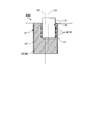
- FIG. 1 is a vertical cross-sectional view showing Embodiment 1 of the present invention.
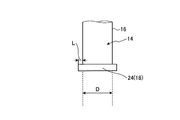
- FIG. 2 is a side view for explaining the protruding amount of the base plate according to the first embodiment of the present invention.
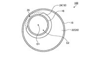
- FIG. 3 is a horizontal sectional view showing the first embodiment of the present invention.
- FIG. 4 is a horizontal sectional view showing a modification of the first embodiment of the present invention.
- FIG. 5 is a horizontal sectional view showing a modification of the first embodiment of the present invention.
- FIG. 6 is a vertical sectional view showing Embodiment 2 of the present invention.
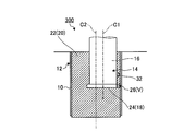
- FIG. 7 is a vertical sectional view showing the third embodiment of the present invention.
- FIG. 8 is a vertical sectional view showing the fourth embodiment of the present invention.
- FIG. 1 is a vertical cross-sectional view showing Embodiment 1 of the present invention.
- FIG. 2 is a side view for explaining the protruding amount of the base plate according to the first embodiment of the present invention.
- FIG. 3 is
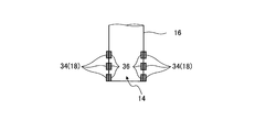
- FIG. 9 is a side view for explaining the protruding amount of the rib according to the fourth embodiment of the present invention.
- FIG. 10 is a horizontal cross-sectional view for explaining the rib protrusion amount according to the fourth embodiment of the present invention.
- FIG. 11 is a vertical sectional view of a rib showing a modification of the fourth embodiment of the present invention.
- FIG. 12 is a vertical cross-sectional view showing an example of a conventional column-pile joint structure.
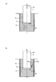
- FIG. 13 is a vertical sectional view which shows an example of the junction structure of a pillar and a pile provided with the conventional baseplate, (a) does not have an inner rib on a pile inner surface, (b) has an inner rib on a pile inner surface Is the case.
- FIG. 14 is a vertical sectional view showing an example of a column / pile joint structure including a conventional base plate when misalignment occurs.
- a pillar-to-pile joint structure 100 includes a pile 10 made of a steel pipe having an upper opening in a steel structure, and an upper end portion of the pile 10 (hereinafter, a pile head).
- a steel column 16 in which a lower end portion (hereinafter referred to as a column base portion) 14 is inserted and arranged in a column 12, a projecting member 18 projecting laterally in the column base portion 14, the column 16 and the pile 10. It joins through the hardening
- the pile 10 can be composed of, for example, a steel pipe pile or a pile head steel pipe winding cast-in-place pile.
- the pile head 12 can be applied to a circular steel pipe or a square steel pipe in which a rib formed from a reinforcing bar or a flat bar or a convex rib formed by rolling on a pipe original plate is attached to the inner surface of the pile head 12.
- a circular steel pipe having no rib will be described as an example.
- the column base part 14 can be comprised with steel materials of arbitrary shapes, such as a round steel pipe, a square steel pipe, and H-section steel, for example.
- a rib made of a reinforcing bar or a flat bar may be provided on the inner surface of the column base part 14.
- a cement-based material such as concrete or mortar can be used, but in the following, a case where concrete 22 is used will be described as an example.
- a disk-shaped steel base plate 24 projecting laterally concentrically with the column core C ⁇ b> 1 of the column 16 on the lower end surface of the column base 14 can be used.
- the amount L of the base plate 24 is generally designed to be equal to or less than the thickness of the base plate so that the pull-out resistance can be effectively transmitted to the column base.
- the base plate 24 instead of providing the base plate 24 on the lower end surface of the column base 14, the base plate 24 may be provided so as to protrude laterally from the outer peripheral surface of the column 16 near the lower end surface.
- the pull-out resistance varies depending on the mounting position of the base plate 24, and increases as the position is closer to the lower end surface of the column base portion 14. For this reason, the attachment position of the base plate 24 is most preferably the lower end surface.
- a gap V having a predetermined size is formed between the inner surface and the inner surface.
- the gap V is formed by the notch 26 between the base plate 24 of the column base 14 and the inner surface of the pile 10, so that the column base 14 can be inserted or becomes easy.
- the concrete 22 that has flowed into the notch 26 of the base plate 24 from above passes through the gap V and wraps around the lower surface side of the base plate 24 as shown by the broken line direction R in FIG. 22 can be filled densely.
- the gap V is a gap having an interval enough to be filled with 20 mm aggregate from the point of filling concrete, and the outer edge of the base plate 24 and the inner surface of the pile 10 are at least about 25 mm. It means a gap formed by being arranged with a separation distance of.
- the column base 14 can be inserted into the pile head 12 when a horizontal misalignment occurs at the pile construction position.
- the insertion workability can be facilitated.
- the concrete 22 can be easily and properly filled into the lower surface side of the base plate 24 through the formed gap V, and the filling property of the concrete can be ensured.
- the gap V can be easily formed in a short time by cutting a part of the base plate 24 and processing the shape at the construction site where the misalignment of the pile 10 is detected.
- the column base part 14 (column 16) was comprised with a circular steel pipe
- this invention is not limited to this.
- the pillar 16 can be formed of a square steel pipe, and as shown in FIG. 5, the pillar 16 can be formed of H-section steel.
- the base plate 24 can be formed of a rectangular plate material.
- the column base portion 14 may be configured as a joint member (see the joint member 3 in FIG. 12) in a conventional joining structure.
- the column can be bonded to the upper side of the column base 14 after the column base 14 as a joint member and the pile head 12 are bonded.
- the column-to-pile joint structure 200 of the second embodiment is such that a vertical through hole 28 is provided at the center of the base plate 24 in the first embodiment.
- the through hole 28 can be configured by, for example, an opening concentric with the base plate 24.
- the concrete 22 filled on the lower surface side of the base plate 24 can be made dense.
- the concrete is placed through the through hole 28 in the center of the base plate 24. By doing so, it becomes possible to place concrete concretely also on the lower surface side of the base plate 24.
- Only one through hole 28 may be provided in the central portion of the base plate 24, or a plurality of through holes 28 may be provided.
- the column-to-pile joint structure 300 of the third embodiment is arranged laterally on the outer peripheral surface of the column base 14 immediately above the notch 26 in the first or second embodiment.
- Convex ribs 32 projecting over are provided.
- the rib 32 can be configured using, for example, a small diameter reinforcing bar.
- the rib 32 made of a reinforcing bar or the like is installed and fixed to the outer surface of the column base 14 by flare welding or the like.
- the ribs 32 are provided on the outer peripheral surface of the column base part 14 immediately above the notch part 26 while ensuring the filling property of the concrete, so that the base plate by providing the notch part 26 is provided. Complementing the decrease in the bearing area of 24, it is possible to secure the same pushing support force and pulling resistance force as before cutting.
- the pillar-to-pile joint structure 400 of the fourth embodiment uses the rib 34 instead of the base plate 24 as the overhang member 18 in the above-described first embodiment, so that the overhang member The arrangement position of 18 is changed.
- the rib 34 has a convex shape projecting annularly from the outer peripheral surface of the column 16 to the side, and can be constituted by, for example, a reinforcing bar, a flat bar, or a convex body formed on the outer peripheral surface by rolling.
- the ribs 34 are provided in a plurality of upper and lower stages at intervals to the column base part 14, and a gap V is formed between each rib 34 and the inner surface of the pile 10. As shown in FIGS. 9 and 10, the protruding amount M of the rib 34 is smaller than the protruding amount L (see FIG. 2) of the base plate 24, although it depends on the number of steps provided.
- the protruding height (protruding amount M) when a plurality of ribs are provided is approximately the sum of the protruding heights of the ribs, and a pull-out resistance is ensured. Therefore, when the three-stage ribs are arranged, the same level of resistance to pulling out can be secured at a height of 1/3 with respect to the protruding height of the base plate to be compared (the overhang amount L).
- the fourth embodiment even if the projecting amount M of each rib 34 is smaller than the projecting amount L of the base plate 24, it is possible to ensure the same bearing area as that of the base plate 24, and the same pushing support force as that of the base plate 24. Pulling resistance can be secured. As a result, the gap V between the rib 34 of the column base 14 and the inner surface of the pile head 12 can be increased as compared with the case where the base plate 24 is provided.
- Similar ribs 36 may be provided on the inner peripheral surface of the column base 14 as shown in FIG. 11. In this case, a larger bearing area can be ensured by the inner and outer ribs 34 and 36 of the column base 14.
- a pile made of a steel pipe having an upper opening, and a steel pillar having a lower end inserted and arranged at the upper end of the pile In the method of joining via the overhanging member projecting laterally at the lower end of the column and the hardened material filled between the column and the pile, the column core of the column and the pile core of the pile are shifted in the horizontal direction.
- the shape of the projecting member is processed or the arrangement position is changed, and a gap is formed between the projecting portion of the projecting member closest to the inner surface of the pile and the inner surface of the pile. For this reason, while being able to insert and arrange the lower end part of a pillar in the inside of a pile, hardening material can be appropriately filled in the circumference of an overhang member through the formed gap.
- the overhanging member is a base plate that protrudes laterally concentrically with the column core of the column at the lower end surface of the column, and a central portion of the base plate Since the through-holes in the vertical direction are provided on the base plate and the hardener can be filled from the upper side to the lower side of the base plate through the through-holes, the hardener can be densely filled on the lower surface side of the base plate.
- the projecting member is a base plate that projects laterally concentrically with the column core of the column at or near the lower end surface of the column. A part of the projecting portion closest to the inner surface of the pile is cut to provide a notch, and a gap is formed between the notch and the inner surface of the pile. For this reason, while being able to insert and arrange the lower end part of a pillar in the inside of a pile, hardening material can be appropriately filled in the circumference of an overhang member through the formed gap.
- the projecting member is a convex rib projecting laterally from the outer peripheral surface of the column, and the rib is vertically arranged in a plurality of steps at the lower end of the column. Since a gap is formed between each rib and the inner surface of the pile, it is possible to secure a bearing area equivalent to that of the base plate even if the protruding amount of each rib is smaller than the protruding amount of the base plate. Pushing support force and pulling resistance force can be secured. As a result, the gap between the rib of the column and the inner surface of the pile can be increased.
- a pile made of a steel pipe having an upper opening and a steel column in which the lower end is inserted and arranged at the upper end of the pile are arranged at the lower end of the column.
- the column core of the column and the pile core of the pile are displaced in the horizontal direction, and the projecting member A gap is formed between the projecting portion closest to the inner surface of the pile and the inner surface of the pile.
- the projecting member is a base plate projecting laterally concentrically with the column core of the column at the lower end surface of the column, and the central portion of the base plate Since a through hole in the vertical direction is provided in the base plate, and the hardener can be filled from the upper side to the lower side of the base plate through this through hole, the hardener filled on the lower surface side of the base plate should be made dense. Can do.
- the overhanging member is a base plate projecting laterally concentrically with the column core of the column at or near the lower end surface of the column.
- a notch is provided in a part of the projecting portion closest to the inner surface of the pile, and a gap is formed between the notch and the inner surface of the pile.
- the notch part is provided. Compensating for the reduction of the bearing area of the base plate due to the provision, it is possible to secure the pushing support force and the pulling resistance force.
- the overhanging member is a convex rib projecting laterally from the outer peripheral surface of the pillar, and the rib has a plurality of upper and lower steps at the lower end portion of the pillar. Since a gap is formed between each rib and the inner surface of the pile, it is possible to secure a bearing area equivalent to that of the base plate even if the protruding amount of each rib is smaller than the protruding amount of the base plate. It is possible to ensure the same pushing support force and pulling resistance force as the base plate. As a result, the gap between the rib of the column and the inner surface of the pile can be increased.
- the joining method and joining structure of a pillar and a pile according to the present invention are useful for joining a pillar and a pile in a steel structure, particularly when the pillar core and the pile core are displaced in the horizontal direction.
- it is suitable for inserting the lower end portion of the column into the pile and properly filling a hardening material such as concrete around the projecting member such as the base plate.
Landscapes
- Engineering & Computer Science (AREA)
- Life Sciences & Earth Sciences (AREA)
- General Life Sciences & Earth Sciences (AREA)
- Mining & Mineral Resources (AREA)
- Paleontology (AREA)
- Civil Engineering (AREA)
- General Engineering & Computer Science (AREA)
- Structural Engineering (AREA)
- Joining Of Building Structures In Genera (AREA)
- Foundations (AREA)
- Piles And Underground Anchors (AREA)
Abstract
Description
まず、本発明の実施の形態1について説明する。
図1に示すように、本実施の形態1の柱と杭の接合構造100は、鉄骨構造物において、上方が開口した鋼管からなる杭10と、この杭10の上端部(以下、杭頭部という。)12に下端部(以下、柱脚部という。)14を挿入配置した鋼製の柱16とを、柱脚部14において側方に張り出した張出部材18と、柱16と杭10の間に充填した硬化材20とを介して接合したものである。
次に、本発明の実施の形態2について説明する。
図6に示すように、本実施の形態2の柱と杭の接合構造200は、上記の実施の形態1において、ベースプレート24の中央部に上下方向の貫通孔28を設けたものである。貫通孔28は、例えばベースプレート24と同心円状の開口で構成することができる。ベースプレート24に貫通孔28を設けることで、柱脚部14の内部上方よりベースプレート24の下側にコンクリート22を充填可能である。
次に、本発明の実施の形態3について説明する。
図7に示すように、本実施の形態3の柱と杭の接合構造300は、上記の実施の形態1または2において、切欠き部26の直上の柱脚部14の外周面に、側方に張り出した凸状のリブ32を設けたものである。リブ32は例えば小径の鉄筋などを用いて構成することができる。鉄筋などからなるリブ32は、フレア溶接等により、柱脚部14の外表面に設置固定される。
次に、本発明の実施の形態4について説明する。
図8に示すように、本実施の形態4の柱と杭の接合構造400は、上記の実施の形態1において、張出部材18としてベースプレート24の代わりにリブ34を用いることで、張出部材18の配置位置を変更したものである。
12 杭頭部(上端部)
14 柱脚部(下端部)
16 柱
18 張出部材
20 硬化材
22 コンクリート(硬化材)
24 ベースプレート(張出部材)
26 切欠き部
28 貫通孔
30 トレミー管
32,36 リブ
34 リブ(張出部材)
100,200,300,400 柱と杭の接合構造
C1 柱芯
C2 杭芯
D 径
L,M 張り出し量
R 方向
V 隙間
Claims (10)
- 上方が開口した鋼管からなる杭と、この杭の上端部に下端部を挿入配置した鋼製の柱とを、柱の下端部において側方に張り出した張出部材と、柱と杭の間に充填した硬化材とを介して接合する方法において、
柱の柱芯と杭の杭芯とを水平方向にずらして配置する場合に、
張出部材の形状を加工または配置位置を変更して、張出部材の杭の内面に最も近接する側の張り出し部分と杭の内面との間に隙間を形成することを特徴とする柱と杭の接合方法。 - 張出部材は、柱の下端面において柱の柱芯と同芯状に側方に張り出したベースプレートであり、
ベースプレートの中央部に上下方向の貫通孔を設け、この貫通孔を通じてベースプレートの上側から下側に硬化材を充填可能にすることを特徴とする請求項1に記載の柱と杭の接合方法。 - 張出部材は、柱の下端面またはその近傍において柱の柱芯と同芯状に側方に張り出したベースプレートであり、
ベースプレートの杭の内面に最も近接する側の張り出し部分の一部を切断して切欠き部を設け、この切欠き部と杭の内面との間に隙間を形成することを特徴とする請求項1に記載の柱と杭の接合方法。 - 切欠き部の直上の柱の外周面に、側方に張り出した凸状のリブを設けることを特徴とする請求項3に記載の柱と杭の接合方法。
- 張出部材は、柱の外周面から側方に張り出した凸状のリブであり、
リブを柱の下端部に上下複数段に設け、各リブと杭の内面との間に隙間を形成することを特徴とする請求項1に記載の柱と杭の接合方法。 - 上方が開口した鋼管からなる杭と、この杭の上端部に下端部を挿入配置した鋼製の柱とを、柱の下端部において側方に張り出した張出部材と、柱と杭の間に充填した硬化材とを介して接合した構造において、
柱の柱芯と杭の杭芯とは水平方向にずれており、
張出部材の杭の内面に最も近接する側の張り出し部分と杭の内面との間に隙間が形成されていることを特徴とする柱と杭の接合構造。 - 張出部材は、柱の下端面において柱の柱芯と同芯状に側方に張り出したベースプレートであり、
ベースプレートの中央部に上下方向の貫通孔が設けられており、この貫通孔を通じてベースプレートの上側から下側に硬化材が充填可能であることを特徴とする請求項6に記載の柱と杭の接合構造。 - 張出部材は、柱の下端面またはその近傍において柱の柱芯と同芯状に側方に張り出したベースプレートであり、
ベースプレートの杭の内面に最も近接する側の張り出し部分の一部には切欠き部が設けられており、この切欠き部と杭の内面との間に隙間が形成されていることを特徴とする請求項6に記載の柱と杭の接合構造。 - 切欠き部の直上の柱の外周面に、側方に張り出した凸状のリブが設けられていることを特徴とする請求項8に記載の柱と杭の接合構造。
- 張出部材は、柱の外周面から側方に張り出した凸状のリブであり、
リブは柱の下端部に上下複数段に設けられており、各リブと杭の内面との間に隙間が形成されていることを特徴とする請求項6に記載の柱と杭の接合構造。
Priority Applications (3)
| Application Number | Priority Date | Filing Date | Title |
|---|---|---|---|
| MYPI2017703008A MY188319A (en) | 2015-02-27 | 2016-02-26 | Column-pile connecting method and connecting structure |
| SG11201706586SA SG11201706586SA (en) | 2015-02-27 | 2016-02-26 | Column-pile connecting method and connecting structure |
| PH12017550085A PH12017550085B1 (en) | 2015-02-27 | 2017-08-18 | Column-pile connecting method and connecting structure |
Applications Claiming Priority (2)
| Application Number | Priority Date | Filing Date | Title |
|---|---|---|---|
| JP2015038876A JP6256383B2 (ja) | 2015-02-27 | 2015-02-27 | 柱と杭の接合方法および接合構造 |
| JP2015-038876 | 2015-02-27 |
Publications (1)
| Publication Number | Publication Date |
|---|---|
| WO2016136980A1 true WO2016136980A1 (ja) | 2016-09-01 |
Family
ID=56788673
Family Applications (1)
| Application Number | Title | Priority Date | Filing Date |
|---|---|---|---|
| PCT/JP2016/055915 Ceased WO2016136980A1 (ja) | 2015-02-27 | 2016-02-26 | 柱と杭の接合方法および接合構造 |
Country Status (5)
| Country | Link |
|---|---|
| JP (1) | JP6256383B2 (ja) |
| MY (1) | MY188319A (ja) |
| PH (1) | PH12017550085B1 (ja) |
| SG (1) | SG11201706586SA (ja) |
| WO (1) | WO2016136980A1 (ja) |
Families Citing this family (3)
| Publication number | Priority date | Publication date | Assignee | Title |
|---|---|---|---|---|
| JP6800764B2 (ja) * | 2017-01-20 | 2020-12-16 | 四国化成工業株式会社 | 基礎部材 |
| JP7479170B2 (ja) * | 2020-03-18 | 2024-05-08 | Jfe建材株式会社 | 防護工及び防護工を構築する方法 |
| JP7132398B1 (ja) * | 2021-06-03 | 2022-09-06 | 日鉄エンジニアリング株式会社 | 基礎構造、基礎構造の設計方法、プログラム及び平屋建て建築物 |
Citations (5)
| Publication number | Priority date | Publication date | Assignee | Title |
|---|---|---|---|---|
| JP2000064305A (ja) * | 1998-08-26 | 2000-02-29 | Susumu Takamatsu | 鉄塔基礎構造とその製法 |
| JP2003105775A (ja) * | 2001-07-24 | 2003-04-09 | Nippon Steel Corp | 鋼管杭と上部構造物との接合構造およびその設計方法 |
| JP2003193481A (ja) * | 2001-12-28 | 2003-07-09 | Daiwa House Ind Co Ltd | 杭頭へのベースプレートの取付け構造 |
| JP2004285737A (ja) * | 2003-03-24 | 2004-10-14 | Tokyo Electric Power Co Inc:The | コンクリート拘束接合部材を用いた鉄塔基礎の構築方法 |
| JP2006104707A (ja) * | 2004-10-01 | 2006-04-20 | Okumura Corp | 鋼柱設置用治具、この鋼柱設置用治具を用いたコンクリート杭と鋼柱の接合工法、並びにコンクリート杭と鋼柱の接合部構造 |
-
2015
- 2015-02-27 JP JP2015038876A patent/JP6256383B2/ja active Active
-
2016
- 2016-02-26 WO PCT/JP2016/055915 patent/WO2016136980A1/ja not_active Ceased
- 2016-02-26 MY MYPI2017703008A patent/MY188319A/en unknown
- 2016-02-26 SG SG11201706586SA patent/SG11201706586SA/en unknown
-
2017
- 2017-08-18 PH PH12017550085A patent/PH12017550085B1/en unknown
Patent Citations (5)
| Publication number | Priority date | Publication date | Assignee | Title |
|---|---|---|---|---|
| JP2000064305A (ja) * | 1998-08-26 | 2000-02-29 | Susumu Takamatsu | 鉄塔基礎構造とその製法 |
| JP2003105775A (ja) * | 2001-07-24 | 2003-04-09 | Nippon Steel Corp | 鋼管杭と上部構造物との接合構造およびその設計方法 |
| JP2003193481A (ja) * | 2001-12-28 | 2003-07-09 | Daiwa House Ind Co Ltd | 杭頭へのベースプレートの取付け構造 |
| JP2004285737A (ja) * | 2003-03-24 | 2004-10-14 | Tokyo Electric Power Co Inc:The | コンクリート拘束接合部材を用いた鉄塔基礎の構築方法 |
| JP2006104707A (ja) * | 2004-10-01 | 2006-04-20 | Okumura Corp | 鋼柱設置用治具、この鋼柱設置用治具を用いたコンクリート杭と鋼柱の接合工法、並びにコンクリート杭と鋼柱の接合部構造 |
Also Published As
| Publication number | Publication date |
|---|---|
| PH12017550085A1 (en) | 2018-02-12 |
| PH12017550085B1 (en) | 2021-01-15 |
| MY188319A (en) | 2021-11-29 |
| JP2016160616A (ja) | 2016-09-05 |
| SG11201706586SA (en) | 2017-09-28 |
| JP6256383B2 (ja) | 2018-01-10 |
Similar Documents
| Publication | Publication Date | Title |
|---|---|---|
| JP6260906B2 (ja) | 鉄骨構造物杭柱地中梁接合部一体化工法 | |
| JP5131518B2 (ja) | 鋼管杭と鉄骨柱の接合構造 | |
| JP6703307B2 (ja) | 鋼管の接合方法及び接合構造 | |
| JP5456626B2 (ja) | 杭と鉄骨柱との接合構造および接合方法 | |
| JP6702128B2 (ja) | 基礎構造、鋼管杭の杭頭構造、及び基礎構造の施工方法 | |
| JP2019027037A (ja) | 基礎構造、鋼管杭の杭頭構造、及び基礎構造の施工方法 | |
| JP2016186154A (ja) | 杭基礎構造の構築方法、杭基礎構造および基礎部材 | |
| JP2016070028A (ja) | 基礎構造 | |
| KR102254227B1 (ko) | Pc 말뚝캡이 구비된 고강도 콘크리트 말뚝 구조체 및 이의 시공 방법 | |
| JP2010070903A (ja) | プレキャストコンクリート製基礎材およびその連結方法 | |
| JP6256383B2 (ja) | 柱と杭の接合方法および接合構造 | |
| JP2017014766A (ja) | グラウト注入方法 | |
| KR101606439B1 (ko) | 트러스거더와 데크플레이트 간의 결합용 스페이서 | |
| KR101618719B1 (ko) | Cfτ 기둥의 이음구조를 이용한 지하구조물의 역타공법 | |
| JP4861640B2 (ja) | 鉄骨構造物を製作する方法 | |
| JP2020070681A (ja) | 鉄骨部材の接合構造、及び鉄骨部材の接合方法 | |
| JP6529241B2 (ja) | 建物基礎構造、及び建物基礎構造の構築方法 | |
| JP2016205051A (ja) | 構造物の施工方法 | |
| JP2020070589A (ja) | 鉄骨柱の柱脚部の補強構造 | |
| JP2021031926A (ja) | 鉄骨構造物地中梁無しの杭・柱接合部一体化柱脚構造 | |
| JP4209314B2 (ja) | 杭頭部の接合構造及び杭体の築造方法 | |
| WO2012114529A1 (ja) | 杭の補強方法及び杭 | |
| JP2009091899A (ja) | 杭頭補強部材とそれを用いた杭頭補強構造 | |
| KR101657628B1 (ko) | 강관을 이용한 지하구조물의 역타공법 | |
| JP2018119338A (ja) | 既存建物の水平抵抗構造及び既存建物の水平抵抗構造の構築方法 |
Legal Events
| Date | Code | Title | Description |
|---|---|---|---|
| 121 | Ep: the epo has been informed by wipo that ep was designated in this application |
Ref document number: 16755724 Country of ref document: EP Kind code of ref document: A1 |
|
| WWE | Wipo information: entry into national phase |
Ref document number: 11201706586S Country of ref document: SG |
|
| WWE | Wipo information: entry into national phase |
Ref document number: 12017550084 Country of ref document: PH |
|
| WWE | Wipo information: entry into national phase |
Ref document number: 12017550085 Country of ref document: PH |
|
| NENP | Non-entry into the national phase |
Ref country code: DE |
|
| 122 | Ep: pct application non-entry in european phase |
Ref document number: 16755724 Country of ref document: EP Kind code of ref document: A1 |