WO2016136554A1 - 防水コネクタ - Google Patents
防水コネクタ Download PDFInfo
- Publication number
- WO2016136554A1 WO2016136554A1 PCT/JP2016/054555 JP2016054555W WO2016136554A1 WO 2016136554 A1 WO2016136554 A1 WO 2016136554A1 JP 2016054555 W JP2016054555 W JP 2016054555W WO 2016136554 A1 WO2016136554 A1 WO 2016136554A1
- Authority
- WO
- WIPO (PCT)
- Prior art keywords
- housing
- elastic
- terminal
- terminal pin
- waterproof connector
- Prior art date
- Legal status (The legal status is an assumption and is not a legal conclusion. Google has not performed a legal analysis and makes no representation as to the accuracy of the status listed.)
- Ceased
Links
Images





Classifications
-
- H—ELECTRICITY
- H01—ELECTRIC ELEMENTS
- H01R—ELECTRICALLY-CONDUCTIVE CONNECTIONS; STRUCTURAL ASSOCIATIONS OF A PLURALITY OF MUTUALLY-INSULATED ELECTRICAL CONNECTING ELEMENTS; COUPLING DEVICES; CURRENT COLLECTORS
- H01R9/00—Structural associations of a plurality of mutually-insulated electrical connecting elements, e.g. terminal strips or terminal blocks; Terminals or binding posts mounted upon a base or in a case; Bases therefor
- H01R9/22—Bases, e.g. strip, block, panel
- H01R9/223—Insulating enclosures for terminals
-
- H—ELECTRICITY
- H01—ELECTRIC ELEMENTS
- H01R—ELECTRICALLY-CONDUCTIVE CONNECTIONS; STRUCTURAL ASSOCIATIONS OF A PLURALITY OF MUTUALLY-INSULATED ELECTRICAL CONNECTING ELEMENTS; COUPLING DEVICES; CURRENT COLLECTORS
- H01R13/00—Details of coupling devices of the kinds covered by groups H01R12/70 or H01R24/00 - H01R33/00
- H01R13/46—Bases; Cases
- H01R13/52—Dustproof, splashproof, drip-proof, waterproof, or flameproof cases
-
- H—ELECTRICITY
- H01—ELECTRIC ELEMENTS
- H01R—ELECTRICALLY-CONDUCTIVE CONNECTIONS; STRUCTURAL ASSOCIATIONS OF A PLURALITY OF MUTUALLY-INSULATED ELECTRICAL CONNECTING ELEMENTS; COUPLING DEVICES; CURRENT COLLECTORS
- H01R13/00—Details of coupling devices of the kinds covered by groups H01R12/70 or H01R24/00 - H01R33/00
- H01R13/46—Bases; Cases
- H01R13/52—Dustproof, splashproof, drip-proof, waterproof, or flameproof cases
- H01R13/521—Sealing between contact members and housing, e.g. sealing insert
Definitions
- the present invention relates to a waterproof connector used as an information terminal such as a notebook PC, a tablet terminal, a wearable terminal, a mobile phone, or an I / O connector of a POS terminal.
- FIG. 10 An example of a conventional waterproof connector is shown in FIG.
- the waterproof connector 10 of FIG. 10 has a structure in which a receiving pin (terminal pin) 3 is incorporated into a resin housing 4 using an internal rubber 1 and an external rubber 2 for watertight sealing.
- the inner rubber 1, the outer rubber 2, the receiving pin 3 and the resin housing 4 are prepared as shown in FIG. 10A, and the inner rubber 1 is fitted into the receiving pin 3 as shown in FIG. Then, they are fitted into the resin housing 4 (FIG. 3C). Further, the external rubber 2 is fitted into the resin housing 4 as shown in FIG.
- the watertight seal between the receiving pin 3 and the housing 4 is performed with the compressed internal rubber 1, and the watertight seal between the housing 4 and the exterior body 15 of the built-in side device (various terminals, etc.) is provided between the housing 4 and the exterior body 15. This is performed by the external rubber 2 sandwiched and compressed.
- the waterproof connector 10 shown in FIG. 10 requires three processes for assembly, and there is a problem that the number of manufacturing steps is large. Further, when the inner rubber 1 is fitted into the resin housing 4, in order to smoothly move the inner rubber 1 to the specified position, it is necessary to provide a guide taper 4a on the inner periphery of the housing. Had to be set larger.
- FIG. 11 Another example of a conventional waterproof connector is shown in FIG.
- the waterproof connector 20 in FIG. 11 has a structure in which a resin housing 22 is insert-molded together with a terminal member 21 and an external rubber 23 is fitted therein.
- the watertight seal between the terminal member 21 and the resin housing 22 is assumed to be in close contact by insert molding, and the watertight seal between the housing 22 and the exterior body 15 of the built-in side device is the housing 22 and the exterior body. 15 is performed by an external rubber 23 sandwiched between 15 and 15 to be in a compressed state.
- the waterproof connector 20 of FIG. 11 insert-molds the resin housing 22 together with the terminal member 21, there are few structural restrictions at the time of assembly and the height can be reduced.
- the waterproof performance by insert molding is between the terminal member 21 and the resin housing 22. Is uncertain in heat change (for example, due to soldering or the like). In order to avoid this uncertainty, special bonding techniques are required. Further, the external rubber 23 had to be fitted in a separate process.
- the conventional example in FIG. 10 has many manufacturing steps and there is a problem that it is difficult to reduce the height of the resin housing.
- the conventional example in FIG. 11 is reliable in the adhesion between the terminal member and the resin housing. There's a problem.
- the present invention has been made in view of such a situation, and its object is to devise the structure of the housing and the elastic body, thereby simplifying the assembly process and reducing the height while maintaining a reliable waterproof structure.
- An object of the present invention is to provide a waterproof connector.
- the waterproof connector includes an insulating housing, an insulating elastic body held by the housing, and a terminal pin that penetrates the elastic body and is held by the housing.
- the elastic body includes an inner elastic portion and an outer elastic portion defined by the housing, and a connecting portion that connects the inner elastic portion and the outer elastic portion, and the inner side through which the terminal pin passes.
- a wall portion that contacts the elastic portion in a compressed state is provided in the housing.
- the wall portion may be formed over the entire circumference so as to surround the terminal pin.
- the housing has a tunnel in a portion that divides the inner elastic portion and the outer elastic portion, and the communication portion is formed in the tunnel.
- the housing includes a base portion that supports a bottom surface of the elastic body, and a terminal holding portion that protrudes from an upper surface of the base portion and partitions the inner elastic portion and the outer elastic portion,
- the terminal holding portion is formed with a recess having a portion into which the head of the terminal pin fits and the wall portion,
- the tunnel may have a configuration in which an outer periphery of the terminal holding portion and the recess are in communication.
- the base portion may have a through hole into which an insertion end portion of the terminal pin is fitted, and a groove portion extending from the through hole to a side surface of the base portion may be formed on the bottom surface of the base portion.
- the waterproof connector according to the present invention it is possible to simplify the assembly process and reduce the height while maintaining a reliable waterproof structure by devising the structure of the insulating housing and the insulating elastic body.
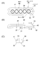
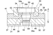
- FIG. 2 is an AA enlarged sectional view of FIG. 1.
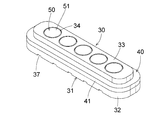
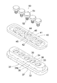
- FIG. 4 is a perspective view showing a cross section by cutting out a part of FIG. 3. The separation figure which shows the shape of each member of embodiment.
- the expanded sectional side view which shows the state which built the waterproof connector shown in embodiment into the built-in side apparatus (various terminals etc.). It is an example of the conventional waterproof connector, (A) is an exploded view, (B) is an exploded view of a state where internal rubber is fitted into a terminal pin, and (C) is a case where internal rubber is fitted into a terminal pin. (D) is sectional drawing of the completion state of an assembly. Sectional drawing which shows the other example of the conventional waterproof connector.
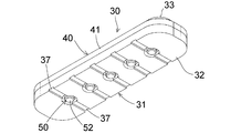
- the waterproof connector 30 penetrates the elastic body 40, an insulating housing 31 made of hard resin (plastic), an insulating elastic body 40 such as rubber held by the housing 31, and the elastic body 40.
- a metal conductor terminal pin (receiving pin) 50 held by the housing 31 is provided.
- the vertical direction is defined as shown in FIG.
- the terminal pin 50 is a portion that comes into electrical contact with the contact on the connection partner side, and has a disk-shaped head portion 51 and a columnar portion 52 having a smaller diameter than that.
- a circular ring-shaped convex portion 53 for waterproofing and an annular convex portion 54 for preventing slipping are formed so as to go around.
- the slip-out preventing annular convex portion 54 is located closer to the distal end side (lower end side) of the cylindrical portion 52 than the waterproof annular convex portion 53.
- the insulating housing 31 includes a base portion 32 that supports the bottom surface of the insulating elastic body 40 and a terminal holding portion 33 that partially protrudes from the top surface of the base portion 32.
- the upper surface of the base portion 32 supports the bottom surface of the elastic body 40 and extends outside the outer periphery of the terminal holding portion 33.
- the terminal holding part 33 holds the terminal pin 50 in the vertical direction and partitions the insulating elastic body 40 into an outer elastic part 41 and an inner elastic part 42.
- the terminal holding portion 33 is formed with a stepped cylindrical recess 34 having a portion in which the head 51 of the terminal pin 50 is fitted for each of a plurality (five in the illustrated example) of the terminal pins 50.
- the central axis 34 c of the stepped cylindrical recess 34 is perpendicular to the upper surface of the base portion 32 (that is, the vertical direction).
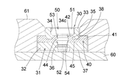
- the stepped cylindrical recess 34 includes a step 34 a that supports the lower surface of the head 51, and an inner peripheral wall 35 that surrounds the columnar portion 52 of the terminal pin 50 at a position below the step 34 a. .
- the inner peripheral wall portion 35 surrounds the entire circumference of the columnar portion 52.
- a tunnel 38 is formed in the diameter direction of the concave part 34 to communicate the concave part 34 with the outer periphery of the terminal holding part 33.
- the bottom surfaces of the concave portion 34 and the tunnel 38 are the upper surface of the base portion 32, and the direction of the tunnel 38 is also a direction orthogonal to the longitudinal direction of the base portion 32.
- a through hole 36 that communicates with the recess 34 and is concentric with the base portion 32 and can press-fit the columnar portion 52 of the terminal pin 50 (that is, slightly smaller than the outer diameter of the press-fit portion of the columnar portion 52). Is formed.
- the insulating elastic body 40 is integrally formed with the insulating housing 31 by so-called two-body molding. After the insulating housing 31 is resin-molded in the mold, a part of the mold is moved. After forming the molding space of the elastic body 40, the elastic body material is injected to form the elastic body 40 having a desired shape. As shown in FIG. 5 and FIG. 7 and FIG. 8 before the terminal pin 50 is inserted, the elastic body 40 is formed by the elastic material entering the outer elastic portion 41 surrounding the outer periphery of the terminal holding portion 33 and the tunnel 38. The connecting portion 45 is formed, and the inner elastic portion 42 is formed by an elastic material entering the inside of the stepped cylindrical recess 34 via the tunnel 38. FIG.
- FIG. 5 is an exploded view for easy understanding of the shape of each member, and the housing 31 and the elastic body 40 are shown separated, but the elastic body 40 is actually separated from the housing 31. It cannot be formed independently.
- a through hole in which the cylindrical portion 52 of the terminal pin 50 can be press-fitted into the inner elastic portion 42 concentrically with the stepped cylindrical concave portion 34 (that is, slightly smaller than the outer diameter of the press-fitted portion of the cylindrical portion 52). 44 is formed.
- the upper openings of the through holes 36 of the base portion 32 and the through holes 44 of the inner elastic portion 42 are tapered upward so as to facilitate the press-fitting of the terminal pins 50.
- the through hole 36 is a stepped hole, and the bottom surface side opening portion has a large diameter by forming a step portion 36a.
- the base portion 32 On the bottom surface of the insulating housing 31 (the bottom surface of the base portion 32), the base portion 32 extends from the lower end opening portion of the through hole 36 that extends to the insertion side end portion (lower end portion of the cylindrical portion 52) of the terminal pin 50.
- a groove 37 reaching the side surface (outer periphery) is formed. The groove portion 37 releases the gas generated during soldering between a terminal pin 50 and a substrate 60 (a substrate included in an embedded device such as an information terminal or a POS terminal), which will be described later with reference to FIG. The floating of the housing 31 from the substrate 60 is prevented.
- the waterproof connector 30 is assembled after the insulating housing 31 and the insulating elastic body 40 are integrally formed, and then the through hole 44 of the inner elastic portion 42 and the through hole of the base portion 32.
- the cylindrical portion 52 of the terminal pin 50 By inserting (press-fitting) the cylindrical portion 52 of the terminal pin 50 into 36, it can be executed in one step.
- the head 51 of the terminal pin 50 is fitted into a portion above the step 34a of the stepped cylindrical recess 34 of the terminal holding portion 33, and as shown in FIG.
- the waterproof annular convex portion 53 on the outer periphery of the columnar portion 52 fits into the through hole 44 of the inner elastic portion 42 and compresses the inner elastic portion 42 with the inner peripheral wall portion 35.
- the outer periphery of the inner peripheral wall portion 35 and the columnar portion 52 is in contact with the inner elastic portion 42 in a compressed state. Thereby, between the terminal pin 50 and the inner side elastic part 42 can be watertight sealed.
- the annular protrusion 54 for preventing the outer periphery of the cylindrical portion 52 from engaging can be engaged with the stepped portion 36 a on the bottom surface side of the through hole 36 to hold the base portion 32 so as not to come out of the terminal pin 50.
- FIG. 9 shows a state in which the waterproof connector 30 is attached to a built-in device such as an information terminal or a POS terminal, and the tip surface of the terminal pin 50 is fixed to the conductor surface of the board 60 of the device by soldering (solder illustration omitted).
- soldering solder illustration omitted.
- the substrate 60 is fixed to the exterior body 61 of the apparatus with screws or the like, the laminated portion of the base portion 32 and the outer elastic portion 41 is compressed and sandwiched between the substrate 60 and the exterior body 61. Thereby, between the outer side elastic part 41 and the exterior body 61 is watertightly sealed.
- the exterior body 61 is an insulator and is, for example, a hard resin.
- the head 51 of the terminal pin 50 exposed to the outside comes into electrical contact with the contact on the connection partner side.
- the waterproof connector 30 is formed by integrally forming the insulating housing 31 and the insulating elastic body 40, and a part of the elastic body 40 constitutes an inner elastic portion 42 surrounding the columnar portion 52 of the terminal pin 50. Therefore, a taper for guiding (see FIG. 10) when inserting the terminal pin 50 into the housing 31 side becomes unnecessary, and the housing 31 can be lowered, that is, the waterproof connector 30 can be lowered.
- the inner peripheral wall portion 35 of the terminal holding portion 33 formed in the collar housing 31 is provided so as to individually surround each terminal pin 50, and the inner elastic portion 42 surrounded and compressed by the inner peripheral wall portion 35.
- the individual terminal pins 50 can be securely sealed with water.
- the outer elastic portion 41 is disposed on the upper surface of the base portion 32 of the housing 31 and is provided over the entire circumference of the terminal holding portion 33, so that a watertight seal structure can be realized with the exterior body 61 of the built-in side device. .
- the elastic body 40 Since the elastic body 40 is at an intermediate height position in the height direction of the cage housing 31, the elastic body 40 is not exposed on the upper surface side related to the appearance of the built-in device (the outer body 61 on the built-in device side is outside). The elastic body 41 is covered), and the elastic body 40 is not exposed on the bottom surface side related to the solder heat resistance when mounted on the substrate 60. It is possible to prevent deterioration of the elastic body 40 in the soldering process without impairing the aesthetics of the built-in device.
- the waterproof connector 30 is provided with a two-layered hole formed in the inner elastic portion 42 of the elastic body 40 and the base portion 32 of the housing 31. That is, the through hole 44 for inserting the terminal pin 50 and the through hole 36 are continuously provided concentrically, and the through hole 36 holds the terminal pin 50 in a fixed position in order to maintain waterproofness. In order to do so, the hole diameter and length can be set separately.
- the two-layered holes formed in the inner elastic portion 42 of the heel elastic body 40 and the base portion 32 of the housing 31 insert the terminal pin 50 from the through hole 44 side of the inner elastic portion 42, so that the terminal pin 50
- the insertion side end is engaged and held by the through hole 36 of the base portion 32, and the inner elastic portion 42 is prevented from being deformed by the upper surface of the base portion 32 of the housing 31 and the inner peripheral wall portion 35 of the terminal holding portion 33. It has become. Therefore, the positioning accuracy of the terminal pin 50 can be improved, and the waterproofness of the terminal pin 50 by the inner elastic portion 42 can be sufficiently secured.
- the shape of the terminal pin can be changed as appropriate, and the inner diameter and length of the through hole on the housing side and the through hole on the inner elastic portion can be set according to this.
Landscapes
- Connector Housings Or Holding Contact Members (AREA)
Abstract
ハウジングと弾性体の構造を工夫することにより、確実な防水構造を保ちつつ、組立工程の簡略化及び低背化を図る。 絶縁性ハウジング(31)と、ハウジング(31)で保持される絶縁性弾性体(40)と、弾性体(40)を貫通しかつハウジング(31)で保持される端子ピン(50)とを備える。弾性体(40)はハウジング(31)によって区画された外側弾性部(41)及び内側弾性部(42)と、外側弾性部(41)及び内側弾性部(42)を連結している連絡部(43)とを有し、端子ピン(50)が貫通している内側弾性部(42)が圧縮された状態で当接する壁部(35)がハウジング(31)に設けられている。
Description
本発明は、ノートPC、タブレット端末、ウェアラブル端末、携帯電話等の情報端末や、POS端末等のI/Oコネクタ等として用いられる防水コネクタに関する。
従来の防水コネクタの1例を図10に示す。図10の防水コネクタ10は、水密シール用に内部ゴム1及び外部ゴム2を用いて受けピン(端子ピン)3を樹脂ハウジング4に組み込む構造である。組立順に説明すると、まず図10(A)のように内部ゴム1、外部ゴム2、受けピン3及び樹脂ハウジング4を用意し、同図(B)のように受けピン3に内部ゴム1を嵌め込み、それらを樹脂ハウジング4に嵌め込む(同図(C))。さらに、図10(D)のように樹脂ハウジング4に外部ゴム2を嵌め込む。受けピン3とハウジング4間の水密シールは圧縮状態の内部ゴム1で行われ、ハウジング4と組込み側装置(各種端末等)の外装体15間の水密シールは、ハウジング4と外装体15とで挟まれて圧縮状態とされた外部ゴム2によって行われる。
図10の防水コネクタ10では組立に3工程必要で、製造工数が多いきらいがあった。また、内部ゴム1を樹脂ハウジング4に嵌合させる際は、内部ゴム1を円滑に規定位置まで移動させるために、ハウジング内周に誘い込みのテーパー4aを設ける必要があり、ハウジング4の高さ寸法を大きく設定する必要があった。
従来の防水コネクタの他の例を図11に示す。図11の防水コネクタ20は、端子部材21と共に樹脂ハウジング22をインサート成形し、これに外部ゴム23を嵌め込む構造である。端子部材21と樹脂ハウジング22間の水密シールはインサート成形で両者が密着していることが前提となっており、ハウジング22と組込み側装置の外装体15間の水密シールは、ハウジング22と外装体15とで挟まれて圧縮状態とされた外部ゴム23によって行われる。
図11の防水コネクタ20は端子部材21と共に樹脂ハウジング22をインサート成形するため、組立時の構造的制約が少なく低背化が可能だが、インサート成形による防水性能は、端子部材21と樹脂ハウジング22間の密着性が熱変化(例えば、はんだ付け等に起因するもの)において不確実である。この不確実性を回避するためには特殊な接着技術が必要である。また、外部ゴム23は別工程で嵌め込む必要があった。
上記したように、図10の従来例は製造工数が多く、また樹脂ハウジングの低背化が困難である問題があり、図11の従来例は端子部材と樹脂ハウジングとの密着性の信頼性に問題がある。
本発明はこうした状況を認識してなされたものであり、その目的は、ハウジングと弾性体の構造を工夫することにより、確実な防水構造を保ちつつ、組立工程の簡略化及び低背化を図ることのできる防水コネクタを提供することにある。
本発明のある態様は防水コネクタである。この防水コネクタは、絶縁性ハウジングと、前記ハウジングで保持される絶縁性弾性体と、前記弾性体を貫通しかつ前記ハウジングで保持される端子ピンとを備え、
前記弾性体は前記ハウジングによって区画された内側弾性部及び外側弾性部と、前記内側弾性部及び前記外側弾性部を連結している連絡部とを有し、前記端子ピンが貫通している前記内側弾性部が圧縮状態で接する壁部が前記ハウジングに設けられていることを特徴とする。
前記弾性体は前記ハウジングによって区画された内側弾性部及び外側弾性部と、前記内側弾性部及び前記外側弾性部を連結している連絡部とを有し、前記端子ピンが貫通している前記内側弾性部が圧縮状態で接する壁部が前記ハウジングに設けられていることを特徴とする。
前記態様において、前記壁部が前記端子ピンを取り囲むように全周にわたって形成されているとよい。
前記態様において、前記ハウジングは前記内側弾性部と前記外側弾性部とを区画する部分にトンネルを有し、前記トンネル内に前記連絡部が形成されているとよい。
前記ハウジングは、前記弾性体の底面を支えるベース部と、前記ベース部の上面から突出して前記内側弾性部と前記外側弾性部とを区画する端子保持部とを有し、
前記端子保持部には、複数の前記端子ピンの各々について、前記端子ピンの頭部が嵌合する部分と前記壁部とを有する凹部が形成されていて、
前記トンネルは前記端子保持部の外周と前記凹部とを連通させている構成であるとよい。
前記端子保持部には、複数の前記端子ピンの各々について、前記端子ピンの頭部が嵌合する部分と前記壁部とを有する凹部が形成されていて、
前記トンネルは前記端子保持部の外周と前記凹部とを連通させている構成であるとよい。
前記ベース部は前記端子ピンの挿入端部が嵌合する貫通穴を有し、前記ベース部の底面には前記貫通穴から前記ベース部の側面に至る溝部が形成されているとよい。
なお、以上の構成要素の任意の組合せ、本発明の表現を方法やシステムなどの間で変換したものもまた、本発明の態様として有効である。
本発明に係る防水コネクタによれば、絶縁性ハウジングと絶縁性弾性体の構造を工夫することで、確実な防水構造を保ちつつ、組立工程の簡略化及び低背化を実現可能である。
以下、図面を参照しながら本発明の好適な実施の形態を詳述する。なお、各図面に示される同一または同等の構成要素、部材、処理等には同一の符号を付し、適宜重複した説明は省略する。また、実施の形態は発明を限定するものではなく例示であり、実施の形態に記述されるすべての特徴やその組み合わせは必ずしも発明の本質的なものであるとは限らない。
図1乃至図6に示すように、防水コネクタ30は、硬質樹脂(プラスチック)製の絶縁性ハウジング31と、ハウジング31で保持されるゴム等の絶縁性弾性体40と、弾性体40を貫通しかつハウジング31で保持される金属導体の端子ピン(受けピン)50とを備えている。なお、図2のように上下方向を定義する。
端子ピン50は接続相手側の接触子と接触して電気的に導通する部分であり、円板状頭部51とこれより小径の円柱状部52とを有し、円柱状部52の外周を周回するように、防水性能を高めるための防水用円環状凸部53及び抜け防止用円環状凸部54が形成されている。抜け防止用円環状凸部54は防水用円環状凸部53よりも円柱状部52の先端側(下端側)に位置している。
絶縁性ハウジング31は、絶縁性弾性体40の底面を支えるベース部32と、ベース部32の上面から部分的に突出する端子保持部33とを有している。ベース部32の上面は弾性体40の底面を支持するとともに、端子保持部33の外周よりも外側に拡がっている。端子保持部33は、端子ピン50を上下方向に保持するとともに、絶縁性弾性体40を外側弾性部41と内側弾性部42とに区画するものである。端子保持部33には、複数(図示の場合、5個)の端子ピン50の各々について、端子ピン50の頭部51が嵌合する部分を有する段付き円柱状凹部34が形成されている。段付き円柱状凹部34の中心軸34cはベース部32の上面に垂直(つまり上下方向)である。段付き円柱状凹部34は、頭部51の下面を支える段部34aを有し、かつ段部34aよりも下方位置で端子ピン50の円柱状部52を囲む内周壁部35を有している。内周壁部35は円柱状部52の全周を囲んでいる。端子保持部33には、凹部34と端子保持部33の外周とを連通させるトンネル38が凹部34の直径方向に形成されている。凹部34及びトンネル38の底面はベース部32の上面であり、トンネル38の向きはベース部32の長手方向に直交する向きでもある。ベース部32には凹部34と連通し、かつ同心で、端子ピン50の円柱状部52を圧入可能な(つまり、円柱状部52の圧入部の外径よりも僅かに小径の)貫通穴36が形成されている。
絶縁性弾性体40は、いわゆる二体成形で絶縁性ハウジング31と共に一体的に形成されるものであり、金型内で絶縁性ハウジング31を樹脂成形した後、前記金型の一部を動かして弾性体40の成形空間を形成してから弾性体材料を注入して所望形状の弾性体40を成形している。図5、及び端子ピン50挿入前の図7及び図8に示すように、弾性体40は、端子保持部33の外周を囲む外側弾性部41と、トンネル38内に弾性体材料が入り込むことで形成される連絡部45と、トンネル38を経由して段付き円柱状凹部34の内側に弾性体材料が入り込むことで形成される内側弾性部42とを有する。なお、図5は各部材の形状を分かり易く示すための分離図であって、ハウジング31と弾性体40とが分離されて示されるが、実際には弾性体40はハウジング31と分離した状態で独立に形成することはできない。内側弾性部42には、段付き円柱状凹部34と同心で端子ピン50の円柱状部52を圧入可能な(つまり、円柱状部52の圧入部の外径よりも僅かに小径の)貫通穴44が形成されている。ベース部32の貫通穴36及び内側弾性部42の貫通穴44の上側開口部は、端子ピン50の圧入を容易にするために上方に向けてテーパー状に拡がっている。また、貫通穴36は段付き穴であって、その底面側開口部は段部36aを形成することで、大径となっている。
絶縁性ハウジング31の底面(ベース部32の底面)には、端子ピン50の挿入側端部(円柱状部52の下端部)に対して拡がった貫通穴36の下端開口部からベース部32の側面(外周)に至る溝部37が形成されている。溝部37は、図9で後述する端子ピン50と基板60(情報端末や、POS端末等の組込み側装置が有する基板)とのはんだ付けの際に発生するガスを外部に放出して、絶縁性ハウジング31の基板60からの浮き上がりを防止する。
防水コネクタ30の組立は、図7及び図8に示すように、絶縁性ハウジング31と絶縁性弾性体40とを一体的に成形後、内側弾性部42の貫通穴44及びベース部32の貫通穴36に対して端子ピン50の円柱状部52を挿入(圧入)することにより、1工程で実行することができる。端子ピン50の挿入後は、端子ピン50の頭部51が、端子保持部33の段付き円柱状凹部34の段部34aより上の部分に嵌合し、図2等に示すように、円柱状部52外周の防水用円環状凸部53が内側弾性部42の貫通穴44に嵌り込んで内周壁部35との間で内側弾性部42を圧縮する。内周壁部35及び円柱状部52外周は圧縮状態の内側弾性部42に当接する。これにより、端子ピン50と内側弾性部42間を水密シールすることができる。円柱状部52外周の抜け防止用円環状凸部54は貫通穴36の底面側の段部36aと係合して、ベース部32が端子ピン50を抜けないように保持することができる。
図9は防水コネクタ30を情報端末や、POS端末等の組込み側装置に取り付けた状態であり、装置の基板60の導体面に端子ピン50の先端面がはんだ付けで固着され(はんだ図示省略)、かつ装置の外装体61に基板60をビス等で固定する際に、基板60と外装体61との間でベース部32及び外側弾性部41の積層部分が圧縮挟持される。これにより、外側弾性部41と外装体61間が水密シールされることになる。外装体61は絶縁体であって、例えば硬質樹脂等である。外部に露出した端子ピン50の頭部51が接続相手側の接触子と接触して電気的に導通するようになっている。
本実施の形態によれば、下記の効果を奏することができる。
(1) 防水コネクタ30は、絶縁性ハウジング31と絶縁性弾性体40とを一体的に成形し、弾性体40の一部が端子ピン50の円柱状部52を囲む内側弾性部42を構成しているため、ハウジング31側に端子ピン50を挿入する際の誘い込みのテーパー(図10参照)が不要となり、ハウジング31の低背化、すなわち防水コネクタ30の低背化が可能である。
(2) 絶縁性ハウジング31と絶縁性弾性体40とを一体的に成形することで、弾性体40のハウジング31への組込み工程が不要になり、組立工程の簡略化が可能である。
(3) 外側弾性部41と内側弾性部42とは、ハウジング31のトンネル38を通る連絡部45で繋がった状態でハウジング31に設けられているため、外側弾性部41及び内側弾性部42がハウジング31から脱落することが無い。
(4) ハウジング31に形成された端子保持部33の内周壁部35が各端子ピン50を個別に囲むように設けられており、内周壁部35で囲まれかつ圧縮された内側弾性部42で個々の端子ピン50を確実に水密シール可能である。図11の従来例において、端子部材21と共に樹脂ハウジング22をインサート成形する場合に問題となる熱変化による接合密着性の劣化、喪失について考慮しなくて済む。
(5) 外側弾性部41はハウジング31のベース部32上面に配置され、かつ端子保持部33の全周にわたって設けられており、組込み側装置の外装体61との間で水密シール構造を実現できる。
(6) ハウジング31の高さ方向において、弾性体40は中間高さ位置にあるため、組込み側装置の外観に関わる上面側に弾性体40が露出せず(組込み装置側の外装体61で外側弾性部41は覆われる)、また基板60への実装時のはんだ耐熱性に関わる底面側にも弾性体40は露出しない。組込み側装置の美観を損なうことがなく、はんだ付け工程での弾性体40の劣化を防止できる。
(7) 防水コネクタ30には、弾性体40の内側弾性部42と、ハウジング31のベース部32とに形成された2層状の穴が設けられている。つまり、端子ピン50を挿入する貫通穴44及び貫通穴36が連続して同心に設けられており、貫通穴44は防水性を維持するために、貫通穴36は端子ピン50を定位置に保持するために、それぞれ別々に穴径及び長さを設定することができる。
(8) 弾性体40の内側弾性部42と、ハウジング31のベース部32とに形成された2層状の穴は、端子ピン50を内側弾性部42の貫通穴44側から挿入し、端子ピン50の挿入側端部をベース部32の貫通穴36で係合、保持する構造であり、ハウジング31のベース部32上面及び端子保持部33の内周壁部35で内側弾性部42の変形を抑える構造となっている。従って、端子ピン50の位置決め精度を向上させることが可能で、また内側弾性部42による端子ピン50の防水性を充分確保できる。
(9) 絶縁性ハウジング31の底面に、端子ピン50の挿入側端部に対して拡がった貫通穴36の底面側開口部からベース部32の側面に至る溝部37が形成されているため、組込み側装置の基板60と端子ピン50とのはんだ付けの際に発生するガスを溝部37を通して外部に放出することができる。絶縁性ハウジング31の基板60からの浮き上がりや、端子ピン50の基板60からの浮き上がりを防止することができる。これにより、複数の端子ピン50頭部51上面の高さが基板に対して不揃いになることを回避できる。
以上、実施の形態を例に本発明を説明したが、実施の形態の各構成要素や各処理プロセスには請求項に記載の範囲で種々の変形が可能であることは当業者に理解されるところである。以下、変形例について触れる。
端子ピンの形状は適宜変更可能であり、これに合わせてハウジング側の貫通穴及び内側弾性部の貫通穴の内径及び長さを設定することができる。
10,20,30 防水コネクタ
15,70 外装体
31 絶縁性ハウジング
32 ベース部
33 端子保持部
34 段付き円柱状凹部
34a,36a 段部
35 内周壁部
36 貫通穴
37 溝部
38 トンネル
40 絶縁性弾性体
41 外側弾性部
42 内側弾性部
44 貫通穴
45 連絡部
50 端子ピン
51 円板状頭部
52 円柱状部
53 防水用円環状凸部
54 抜け防止用円環状凸部
60 基板
15,70 外装体
31 絶縁性ハウジング
32 ベース部
33 端子保持部
34 段付き円柱状凹部
34a,36a 段部
35 内周壁部
36 貫通穴
37 溝部
38 トンネル
40 絶縁性弾性体
41 外側弾性部
42 内側弾性部
44 貫通穴
45 連絡部
50 端子ピン
51 円板状頭部
52 円柱状部
53 防水用円環状凸部
54 抜け防止用円環状凸部
60 基板
Claims (5)
- 絶縁性ハウジングと、
前記ハウジングで保持される絶縁性弾性体と、
前記弾性体を貫通しかつ前記ハウジングで保持される端子ピンとを備え、
前記弾性体は前記ハウジングによって区画された内側弾性部及び外側弾性部と、前記内側弾性部及び前記外側弾性部を連結している連絡部とを有し、
前記端子ピンが貫通している前記内側弾性部が圧縮状態で接する壁部が前記ハウジングに設けられていることを特徴とする防水コネクタ。 - 前記壁部が前記端子ピンを取り囲むように全周にわたって形成されていることを特徴とする請求項1に記載の防水コネクタ。
- 前記ハウジングは前記内側弾性部と前記外側弾性部とを区画する部分にトンネルを有し、前記トンネル内に前記連絡部が形成されていることを特徴とする請求項1又は2に記載の防水コネクタ。
- 前記ハウジングは、前記弾性体の底面を支えるベース部と、前記ベース部の上面から突出して前記内側弾性部と前記外側弾性部とを区画する端子保持部とを有し、
前記端子保持部には、複数の前記端子ピンの各々について、前記端子ピンの頭部が嵌合する部分と前記壁部とを有する凹部が形成されていて、
前記トンネルは前記端子保持部の外周と前記凹部とを連通させていることを特徴とする請求項3に記載の防水コネクタ。 - 前記ベース部は前記端子ピンの挿入端部が嵌合する貫通穴を有し、前記ベース部の底面には前記貫通穴から前記ベース部の側面に至る溝部が形成されていることを特徴とする請求項4に記載の防水コネクタ。
Priority Applications (3)
| Application Number | Priority Date | Filing Date | Title |
|---|---|---|---|
| US15/552,919 US10164353B2 (en) | 2015-02-23 | 2016-02-17 | Waterproof connector |
| DE112016000870.8T DE112016000870B4 (de) | 2015-02-23 | 2016-02-17 | Wasserdichter Verbinder |
| CN201680011683.8A CN107251335B (zh) | 2015-02-23 | 2016-02-17 | 防水连接器 |
Applications Claiming Priority (2)
| Application Number | Priority Date | Filing Date | Title |
|---|---|---|---|
| JP2015033023A JP6514909B2 (ja) | 2015-02-23 | 2015-02-23 | 防水コネクタ |
| JP2015-033023 | 2015-02-23 |
Publications (1)
| Publication Number | Publication Date |
|---|---|
| WO2016136554A1 true WO2016136554A1 (ja) | 2016-09-01 |
Family
ID=56789212
Family Applications (1)
| Application Number | Title | Priority Date | Filing Date |
|---|---|---|---|
| PCT/JP2016/054555 Ceased WO2016136554A1 (ja) | 2015-02-23 | 2016-02-17 | 防水コネクタ |
Country Status (6)
| Country | Link |
|---|---|
| US (1) | US10164353B2 (ja) |
| JP (1) | JP6514909B2 (ja) |
| CN (1) | CN107251335B (ja) |
| DE (1) | DE112016000870B4 (ja) |
| TW (1) | TWI666829B (ja) |
| WO (1) | WO2016136554A1 (ja) |
Families Citing this family (5)
| Publication number | Priority date | Publication date | Assignee | Title |
|---|---|---|---|---|
| JP7011532B2 (ja) * | 2018-05-21 | 2022-01-26 | 日本航空電子工業株式会社 | ダミーピン |
| JP7211750B2 (ja) * | 2018-10-03 | 2023-01-24 | 株式会社ヨコオ | スプリングコネクタ |
| DE102020118046A1 (de) | 2020-07-08 | 2022-01-13 | Fte Automotive Gmbh | Kontaktierungsbaugruppe für ein Magnetventil und Pumpenaggregat mit einer solchen Kontaktierungsbaugruppe |
| US12525740B2 (en) * | 2022-09-27 | 2026-01-13 | Aptiv Technologies AG | Electrical connector with cavity plugs |
| JP7743160B2 (ja) * | 2023-03-27 | 2025-09-24 | 矢崎総業株式会社 | 1極端子台及び該1極端子台の製造方法 |
Citations (3)
| Publication number | Priority date | Publication date | Assignee | Title |
|---|---|---|---|---|
| JPH07267020A (ja) * | 1994-03-31 | 1995-10-17 | Oi Seisakusho Co Ltd | スライドドア用給電装置 |
| JP2001185280A (ja) * | 1999-12-28 | 2001-07-06 | Casio Comput Co Ltd | 携帯電子機器 |
| JP2014135184A (ja) * | 2013-01-09 | 2014-07-24 | Yokowo Co Ltd | 電気コネクタ |
Family Cites Families (20)
| Publication number | Priority date | Publication date | Assignee | Title |
|---|---|---|---|---|
| US4643506A (en) * | 1985-05-17 | 1987-02-17 | Amp Incorporated | Wire seal |
| WO1996037927A1 (en) | 1995-05-25 | 1996-11-28 | The Whitaker Corporation | Sealed electrical connector |
| JP3230956B2 (ja) * | 1995-09-05 | 2001-11-19 | 矢崎総業株式会社 | 防水圧接コネクタ |
| JP3175817B2 (ja) * | 1996-04-05 | 2001-06-11 | 矢崎総業株式会社 | 防水コネクタ |
| JP3247048B2 (ja) * | 1996-08-28 | 2002-01-15 | 矢崎総業株式会社 | リップ付きゴム製品 |
| JP2000133367A (ja) * | 1998-10-20 | 2000-05-12 | Yazaki Corp | 防水コネクタ及び該防水コネクタの組付方法 |
| JP2000133368A (ja) * | 1998-10-20 | 2000-05-12 | Yazaki Corp | 防水コネクタとダミー栓の係止構造 |
| US6511329B2 (en) * | 2001-04-10 | 2003-01-28 | L & K Precision Industry Co., Ltd. | Waterproof connector apparatus |
| DE20203789U1 (de) | 2002-03-08 | 2002-06-06 | Anton Hummel Verwaltungs Gmbh, 79183 Waldkirch | Steckverbinder mit einem abgedichteten Isolierkörper |
| JP4283160B2 (ja) | 2004-05-10 | 2009-06-24 | 矢崎総業株式会社 | コネクタ部を有するケース部材の組付け方法 |
| JP4898302B2 (ja) | 2006-05-31 | 2012-03-14 | 日本無線株式会社 | 車載通信端末装置及びicカード読取装置 |
| JP5051640B2 (ja) * | 2007-08-31 | 2012-10-17 | Necカシオモバイルコミュニケーションズ株式会社 | 電子機器 |
| JP5203094B2 (ja) * | 2008-04-03 | 2013-06-05 | 矢崎総業株式会社 | コネクタ用パッキン構造 |
| US7695285B2 (en) * | 2008-05-29 | 2010-04-13 | Yokowo Co., Ltd. | Spring connector and connector |
| CN201303137Y (zh) * | 2008-11-18 | 2009-09-02 | 勖连科技股份有限公司 | 连接座和连接头 |
| JP2011165330A (ja) * | 2010-02-04 | 2011-08-25 | Yazaki Corp | 防水コネクタ用の弾性シール部材及び防水コネクタ |
| JP5593162B2 (ja) * | 2010-08-18 | 2014-09-17 | 矢崎総業株式会社 | 防水栓 |
| JP5822735B2 (ja) * | 2012-01-16 | 2015-11-24 | 株式会社ヨコオ | 防水機能付きスプリングコネクタ |
| CN103236605B (zh) | 2013-03-07 | 2015-02-25 | 公牛集团有限公司 | 防水插座插孔密封结构 |
| JP2014216826A (ja) | 2013-04-25 | 2014-11-17 | Necカシオモバイルコミュニケーションズ株式会社 | シール性を有する接続構造 |
-
2015
- 2015-02-23 JP JP2015033023A patent/JP6514909B2/ja active Active
-
2016
- 2016-02-17 WO PCT/JP2016/054555 patent/WO2016136554A1/ja not_active Ceased
- 2016-02-17 US US15/552,919 patent/US10164353B2/en active Active
- 2016-02-17 CN CN201680011683.8A patent/CN107251335B/zh active Active
- 2016-02-17 DE DE112016000870.8T patent/DE112016000870B4/de active Active
- 2016-02-22 TW TW105105063A patent/TWI666829B/zh active
Patent Citations (3)
| Publication number | Priority date | Publication date | Assignee | Title |
|---|---|---|---|---|
| JPH07267020A (ja) * | 1994-03-31 | 1995-10-17 | Oi Seisakusho Co Ltd | スライドドア用給電装置 |
| JP2001185280A (ja) * | 1999-12-28 | 2001-07-06 | Casio Comput Co Ltd | 携帯電子機器 |
| JP2014135184A (ja) * | 2013-01-09 | 2014-07-24 | Yokowo Co Ltd | 電気コネクタ |
Also Published As
| Publication number | Publication date |
|---|---|
| JP6514909B2 (ja) | 2019-05-15 |
| US10164353B2 (en) | 2018-12-25 |
| CN107251335B (zh) | 2019-03-29 |
| DE112016000870T5 (de) | 2017-11-16 |
| CN107251335A (zh) | 2017-10-13 |
| TWI666829B (zh) | 2019-07-21 |
| TW201644114A (zh) | 2016-12-16 |
| DE112016000870B4 (de) | 2024-03-21 |
| JP2016157526A (ja) | 2016-09-01 |
| US20180034173A1 (en) | 2018-02-01 |
Similar Documents
| Publication | Publication Date | Title |
|---|---|---|
| US8011967B2 (en) | Watertight connector and method of manufacturing the same | |
| JP6514909B2 (ja) | 防水コネクタ | |
| US9871318B2 (en) | Waterproof electrical connector having a sealer between conatct module and outer shell | |
| EP2779319B1 (en) | Waterproof Ear Jack Socket and Method of Manufacturing the same | |
| US9893459B2 (en) | Electrical connector having a tongue portion extending beyond a metallic shell | |
| JP5905977B1 (ja) | コネクタの製造方法およびコネクタ | |
| KR20170036529A (ko) | 기판 대 기판 커넥터 및 rf 커넥터 일체형 커넥터 조립체 | |
| US20210119377A1 (en) | Waterproof female connector | |
| JP2018101503A (ja) | スライド型コネクタ | |
| JP2006147254A (ja) | 防水コネクタ | |
| EP3483988B1 (en) | Connector | |
| US20140342599A1 (en) | Electrical connector device | |
| WO2014109165A1 (ja) | 電気コネクタ | |
| CN111326936A (zh) | 电连接器组件及其组装方法 | |
| JP2011146286A (ja) | 基板接続コネクタの防水取付け構造 | |
| US7963786B1 (en) | Audio jack | |
| KR101425681B1 (ko) | 휴대폰의 방수방법 및 구조 | |
| JP2017216147A (ja) | コネクタ | |
| KR102019907B1 (ko) | 다극잭 및 그 제조방법과 전자기기 | |
| EP3309905A2 (en) | Mobile terminal, earphone socket and method for manufacturing earphone socket | |
| JP2016091657A (ja) | 同軸コネクタ | |
| US11128081B2 (en) | Easily assembled connector | |
| KR20210154493A (ko) | 방수 스위치 장치 및 이를 채용한 차량 트렁크 도어용 방수 스위치 모듈 | |
| JP2014067560A (ja) | ピン孔と端子ピンの間の防水構造 | |
| JP2004087185A (ja) | 多極性イヤホンプラグ接続装置 |
Legal Events
| Date | Code | Title | Description |
|---|---|---|---|
| 121 | Ep: the epo has been informed by wipo that ep was designated in this application |
Ref document number: 16755301 Country of ref document: EP Kind code of ref document: A1 |
|
| WWE | Wipo information: entry into national phase |
Ref document number: 112016000870 Country of ref document: DE |
|
| 122 | Ep: pct application non-entry in european phase |
Ref document number: 16755301 Country of ref document: EP Kind code of ref document: A1 |