WO2016136520A1 - Outil rotatif - Google Patents
Outil rotatif Download PDFInfo
- Publication number
- WO2016136520A1 WO2016136520A1 PCT/JP2016/054295 JP2016054295W WO2016136520A1 WO 2016136520 A1 WO2016136520 A1 WO 2016136520A1 JP 2016054295 W JP2016054295 W JP 2016054295W WO 2016136520 A1 WO2016136520 A1 WO 2016136520A1
- Authority
- WO
- WIPO (PCT)
- Prior art keywords
- rotary tool
- cutting
- film
- coating
- film thickness
- Prior art date
Links
Images


Classifications
-
- B—PERFORMING OPERATIONS; TRANSPORTING
- B23—MACHINE TOOLS; METAL-WORKING NOT OTHERWISE PROVIDED FOR
- B23C—MILLING
- B23C5/00—Milling-cutters
- B23C5/16—Milling-cutters characterised by physical features other than shape
-
- B—PERFORMING OPERATIONS; TRANSPORTING
- B23—MACHINE TOOLS; METAL-WORKING NOT OTHERWISE PROVIDED FOR
- B23B—TURNING; BORING
- B23B51/00—Tools for drilling machines
-
- B—PERFORMING OPERATIONS; TRANSPORTING
- B23—MACHINE TOOLS; METAL-WORKING NOT OTHERWISE PROVIDED FOR
- B23B—TURNING; BORING
- B23B51/00—Tools for drilling machines
- B23B51/02—Twist drills
-
- B—PERFORMING OPERATIONS; TRANSPORTING
- B23—MACHINE TOOLS; METAL-WORKING NOT OTHERWISE PROVIDED FOR
- B23C—MILLING
- B23C5/00—Milling-cutters
- B23C5/02—Milling-cutters characterised by the shape of the cutter
- B23C5/10—Shank-type cutters, i.e. with an integral shaft
-
- B—PERFORMING OPERATIONS; TRANSPORTING
- B23—MACHINE TOOLS; METAL-WORKING NOT OTHERWISE PROVIDED FOR
- B23D—PLANING; SLOTTING; SHEARING; BROACHING; SAWING; FILING; SCRAPING; LIKE OPERATIONS FOR WORKING METAL BY REMOVING MATERIAL, NOT OTHERWISE PROVIDED FOR
- B23D77/00—Reaming tools
-
- C—CHEMISTRY; METALLURGY
- C23—COATING METALLIC MATERIAL; COATING MATERIAL WITH METALLIC MATERIAL; CHEMICAL SURFACE TREATMENT; DIFFUSION TREATMENT OF METALLIC MATERIAL; COATING BY VACUUM EVAPORATION, BY SPUTTERING, BY ION IMPLANTATION OR BY CHEMICAL VAPOUR DEPOSITION, IN GENERAL; INHIBITING CORROSION OF METALLIC MATERIAL OR INCRUSTATION IN GENERAL
- C23C—COATING METALLIC MATERIAL; COATING MATERIAL WITH METALLIC MATERIAL; SURFACE TREATMENT OF METALLIC MATERIAL BY DIFFUSION INTO THE SURFACE, BY CHEMICAL CONVERSION OR SUBSTITUTION; COATING BY VACUUM EVAPORATION, BY SPUTTERING, BY ION IMPLANTATION OR BY CHEMICAL VAPOUR DEPOSITION, IN GENERAL
- C23C14/00—Coating by vacuum evaporation, by sputtering or by ion implantation of the coating forming material
- C23C14/06—Coating by vacuum evaporation, by sputtering or by ion implantation of the coating forming material characterised by the coating material
- C23C14/0641—Nitrides
-
- C—CHEMISTRY; METALLURGY
- C23—COATING METALLIC MATERIAL; COATING MATERIAL WITH METALLIC MATERIAL; CHEMICAL SURFACE TREATMENT; DIFFUSION TREATMENT OF METALLIC MATERIAL; COATING BY VACUUM EVAPORATION, BY SPUTTERING, BY ION IMPLANTATION OR BY CHEMICAL VAPOUR DEPOSITION, IN GENERAL; INHIBITING CORROSION OF METALLIC MATERIAL OR INCRUSTATION IN GENERAL
- C23C—COATING METALLIC MATERIAL; COATING MATERIAL WITH METALLIC MATERIAL; SURFACE TREATMENT OF METALLIC MATERIAL BY DIFFUSION INTO THE SURFACE, BY CHEMICAL CONVERSION OR SUBSTITUTION; COATING BY VACUUM EVAPORATION, BY SPUTTERING, BY ION IMPLANTATION OR BY CHEMICAL VAPOUR DEPOSITION, IN GENERAL
- C23C14/00—Coating by vacuum evaporation, by sputtering or by ion implantation of the coating forming material
- C23C14/22—Coating by vacuum evaporation, by sputtering or by ion implantation of the coating forming material characterised by the process of coating
- C23C14/34—Sputtering
- C23C14/3485—Sputtering using pulsed power to the target
-
- C—CHEMISTRY; METALLURGY
- C23—COATING METALLIC MATERIAL; COATING MATERIAL WITH METALLIC MATERIAL; CHEMICAL SURFACE TREATMENT; DIFFUSION TREATMENT OF METALLIC MATERIAL; COATING BY VACUUM EVAPORATION, BY SPUTTERING, BY ION IMPLANTATION OR BY CHEMICAL VAPOUR DEPOSITION, IN GENERAL; INHIBITING CORROSION OF METALLIC MATERIAL OR INCRUSTATION IN GENERAL
- C23C—COATING METALLIC MATERIAL; COATING MATERIAL WITH METALLIC MATERIAL; SURFACE TREATMENT OF METALLIC MATERIAL BY DIFFUSION INTO THE SURFACE, BY CHEMICAL CONVERSION OR SUBSTITUTION; COATING BY VACUUM EVAPORATION, BY SPUTTERING, BY ION IMPLANTATION OR BY CHEMICAL VAPOUR DEPOSITION, IN GENERAL
- C23C14/00—Coating by vacuum evaporation, by sputtering or by ion implantation of the coating forming material
- C23C14/22—Coating by vacuum evaporation, by sputtering or by ion implantation of the coating forming material characterised by the process of coating
- C23C14/34—Sputtering
- C23C14/35—Sputtering by application of a magnetic field, e.g. magnetron sputtering
-
- C—CHEMISTRY; METALLURGY
- C23—COATING METALLIC MATERIAL; COATING MATERIAL WITH METALLIC MATERIAL; CHEMICAL SURFACE TREATMENT; DIFFUSION TREATMENT OF METALLIC MATERIAL; COATING BY VACUUM EVAPORATION, BY SPUTTERING, BY ION IMPLANTATION OR BY CHEMICAL VAPOUR DEPOSITION, IN GENERAL; INHIBITING CORROSION OF METALLIC MATERIAL OR INCRUSTATION IN GENERAL
- C23C—COATING METALLIC MATERIAL; COATING MATERIAL WITH METALLIC MATERIAL; SURFACE TREATMENT OF METALLIC MATERIAL BY DIFFUSION INTO THE SURFACE, BY CHEMICAL CONVERSION OR SUBSTITUTION; COATING BY VACUUM EVAPORATION, BY SPUTTERING, BY ION IMPLANTATION OR BY CHEMICAL VAPOUR DEPOSITION, IN GENERAL
- C23C30/00—Coating with metallic material characterised only by the composition of the metallic material, i.e. not characterised by the coating process
- C23C30/005—Coating with metallic material characterised only by the composition of the metallic material, i.e. not characterised by the coating process on hard metal substrates
-
- B—PERFORMING OPERATIONS; TRANSPORTING
- B23—MACHINE TOOLS; METAL-WORKING NOT OTHERWISE PROVIDED FOR
- B23B—TURNING; BORING
- B23B2228/00—Properties of materials of tools or workpieces, materials of tools or workpieces applied in a specific manner
- B23B2228/10—Coatings
- B23B2228/105—Coatings with specified thickness
-
- B—PERFORMING OPERATIONS; TRANSPORTING
- B23—MACHINE TOOLS; METAL-WORKING NOT OTHERWISE PROVIDED FOR
- B23C—MILLING
- B23C2210/00—Details of milling cutters
- B23C2210/40—Flutes, i.e. chip conveying grooves
-
- B—PERFORMING OPERATIONS; TRANSPORTING
- B23—MACHINE TOOLS; METAL-WORKING NOT OTHERWISE PROVIDED FOR
- B23C—MILLING
- B23C2224/00—Materials of tools or workpieces composed of a compound including a metal
-
- B—PERFORMING OPERATIONS; TRANSPORTING
- B23—MACHINE TOOLS; METAL-WORKING NOT OTHERWISE PROVIDED FOR
- B23C—MILLING
- B23C2228/00—Properties of materials of tools or workpieces, materials of tools or workpieces applied in a specific manner
- B23C2228/10—Coating
Definitions
- the present invention relates to a rotary tool including a base material and a film formed on the base material.
- a tool in which a hard film such as TiAlN is provided on the surface of a hard base material such as a WC-based cemented carbide is known.
- a hard film such as TiAlN
- a hard base material such as a WC-based cemented carbide
- Non-Patent Document 1 discloses a tool in which a coating is provided on the surface of a substrate by an arc ion plating (AIP) method.
- AIP arc ion plating
- MS magnetron sputtering
- the degree of improvement in wear resistance by providing the coating may be insufficient.
- the present disclosure aims to provide a rotary tool having excellent wear resistance.
- the rotary tool which concerns on 1 aspect of this invention is equipped with the base material containing a cutting blade part and a groove part, and the film which coat
- the ratio B / A of the film thickness B of the coating covering the surface of the groove is 0.8 or more.
- FIG. 2 is a cross-sectional view taken along the line XX shown in FIG. It is a schematic diagram for demonstrating each area
- the present inventors have found that in the conventional rotary tool, the thickness of the coating formed on the surface of the groove is smaller than the thickness of the coating formed on the surface of the cutting edge. It was found that the film thickness was remarkably small, and this was due to a decrease in wear resistance of the rotary tool. Based on this knowledge, the present inventors consider that there is a problem with conventional film formation methods such as AIP method and MS method, and as an alternative formation method, J. Mater. Res., Vol. 27, No. 5 (2012), 780-792 (Non-patent Document 2), the High Power Impulse Magnetron Sputtering (HiPIMS) method has been studied earnestly. As a result, a rotating tool having excellent wear resistance was completed.
- a rotary tool includes a base material including a cutting edge portion and a groove portion, and a coating that covers the surface of the base material, and a coating that covers the surface of the cutting edge portion.
- the ratio B / A of the film thickness B of the film covering the surface of the groove to the film thickness A is 0.8 or more.
- the rotary tool described above since the wear of the coating covering the surface of the groove can be suppressed, it can have excellent wear resistance.
- the rotary tool is an end mill. Conventionally, in the end mill, the above ratio tended to be particularly small. However, according to the rotary tool, since the ratio can be larger than the conventional one, it is possible to have excellent wear resistance.
- the rotating tool is a drill.
- the ratio tends to be particularly small.
- the ratio can be higher than that of the conventional one, it is possible to have excellent wear resistance.
- the ratio B / A is 1 or more. Thereby, it can be further excellent in wear resistance.
- the film thickness A is 0.1 ⁇ m or more and 10 ⁇ m or less. Thereby, it can be further excellent in wear resistance.
- the film thickness A is 2.0 ⁇ m or more and 6.0 ⁇ m or less. Thereby, it can be further excellent in wear resistance.
- the material of the coating is at least one element selected from the group consisting of Group 4 elements, Group 5 elements, Group 6 elements, aluminum and silicon in the periodic table, boron, One or more compounds composed of at least one element selected from the group consisting of carbon, nitrogen and oxygen.
- the said rotary tool can be provided with the film which has high hardness.
- the present embodiment an embodiment of the present invention (hereinafter referred to as “the present embodiment”) will be described in detail, but the present embodiment is not limited thereto.
- FIG. 1 is a schematic plan view showing an example of a rotary tool according to the present embodiment
- FIG. 2 is a cross-sectional view taken along line XX shown in FIG.
- a four-blade end mill is exemplified.
- the rotary tool 10 includes a base material 11 that is a main body of the rotary tool 10 and a coating 12 that covers the surface of the base material 11.
- the entire surface of the base material 11 constituting the rotary tool 10 may be covered with the coating 12, or a part of the base 11 may be covered.
- the surface of the base material 11 constituting the shank 2 may not be covered but only the surface of the base material constituting the cutting edge 1 may be covered with the coating 12.
- an end mill is illustrated as the rotary tool 10, but a drill can be used in addition to the end mill.
- the rotary tool 10 includes a base material 11 having at least a cutting edge portion for cutting out the work material in contact with the work material, a groove portion for discharging chips, and a coating 12.
- a router, a reamer, etc. can be mentioned besides the above.
- the rotary tool 10 of this embodiment can be suitably used as a rotary tool for high-precision machining.
- the base material 11 is a main body in the shape of the rotary tool 10.
- the base material 11 includes a blade edge 1 and a shank 2.
- the blade edge 1 includes an outer peripheral blade portion 3, a groove portion 4, and a bottom blade portion 5.
- the outer peripheral blade portion 3 and the bottom blade portion 5 are portions for cutting out the work material
- the groove portion 4 is a portion for discharging chips generated by cutting to the outside.
- the outer peripheral blade portion 3 includes a cutting edge portion (not shown) that becomes a portion having no clearance angle with respect to the work material.
- the cutting edge portion is a portion that comes into contact with the work material during cutting.
- region of the outer periphery blade part 3 and the groove part 4 is determined as follows.
- circle S is a virtual circle that includes the cross section of blade edge 1 inside and is drawn by connecting blade edge tip 3 a, and its diameter is D.
- the cutting edge tip 3a is a portion serving as a starting point for cutting out the work material.
- Circle S1 is a virtual circle having a contact point between cutting edge tip 3a and circle S as a center point and radius D1 of 2 / 10D.
- an area located within the virtual circle S ⁇ b> 1 is defined as the outer peripheral blade portion 3.
- Lines L1 and L2 are virtual lines that connect adjacent cutting edge tips 3a and the center point P of the circle S.
- the line L3 is a virtual line that equally divides the angle 2 ⁇ formed by the line L1 and the line L2.
- the circle S2 is a virtual circle whose center point is the contact point between the line L3 and the outer periphery of the substrate 11, and whose radius D2 is 1 / 10D.
- a region located within the virtual circle S2 (including the circle S2) in the outer periphery of the base material 11 is defined as the groove portion 4.
- the base material 11 of the rotary tool As the material of the base material 11, a conventionally known material known as the base material 11 of the rotary tool can be used without any particular limitation. Examples thereof include tungsten carbide (WC) based cemented carbide, cermet, high speed steel, ceramics, cubic boron nitride sintered body, diamond sintered body, and the like. In addition, the base material 11 may be integrally formed, and what combined several components may be used.
- WC tungsten carbide
- the coating 12 covers all or part of the surface of the substrate 11.
- the coating 12 may be a single layer composed of one layer or a multilayer composed of two or more layers.
- the ratio B / A of the film thickness B of the coating 12 covering the surface of the groove 4 to the film thickness A of the coating 12 covering the surface of the cutting edge 6 is 0.8 or more.
- the rotary tool 10 of the present embodiment is excellent in wear resistance
- the rotary tool not only the physical properties of the base material but also the wear resistance expected in design is derived from the physical properties of the coating provided on the surface.
- conventional rotary tools tend not to exhibit the wear resistance as expected in design.
- the ratio B / A of the film thickness B of the coating formed on the surface of the groove to the film thickness A of the coating formed on the surface of the cutting edge is 0. It was found that the wear resistance of the rotary tool was insufficient as a result because the wear resistance of the groove was lower than expected in the design due to being too small, about 5 or less.
- the above ratio is too small because the coating of the conventional rotary tool is manufactured by the MS method or the AIP method.
- the MS method since the ionization rate of atoms serving as targets in the plasma is too low, ions cannot be sufficiently drawn into the groove due to the substrate bias.
- the ionization rate is sufficient in the AIP method, it is necessary to increase the pressure in the chamber in order to reduce the number of metal droplets generated from the target. Thereby, since the pressure in the chamber becomes too high, the mean free path of ions tends to be too short. If the mean free path of ions is short, ions are likely to be scattered, and therefore it becomes difficult to draw ions into the groove. For this reason, in these methods, it is not possible to form a film with a uniform film thickness on the surface of the base material for a rotary tool having a complicated shape as compared with other tools. The film thickness B at the groove located in the intricate portion is reduced.
- the film thickness B is small, the groove will advance faster than expected. Thereby, since the smoothness of a groove part falls and chip
- the rotary tool 10 of this embodiment includes a coating 12 formed by using the HiPIMS method instead of the MS method and the AIP method.
- the HiPIMS method applies high power to the target in a short pulse, so that a high ionization rate can be achieved, and the method is a kind of sputtering method, so the pressure in the chamber can be lowered. It is.
- the coating film 12 having a uniform film thickness is formed on the surface of the substrate 11, and the ratio B / A can show a high value of 0.8 or more. Therefore, since the rotary tool 10 of the present embodiment can solve the above-mentioned problems that the conventional rotary tool has, the rotary tool 10 of the present embodiment has higher wear resistance than the conventional one. be able to. Furthermore, since it has a high wear resistance, it can have a long life, and the cutting accuracy is also improved, so that the surface condition such as the surface roughness of the work material can be improved.
- the rotary tool 10 of this embodiment is suitable as a rotary tool for high-precision machining.
- the film thickness A and the film thickness B of the coating 12 can be measured by cutting the rotary tool 10 in the longitudinal direction (lateral direction in FIG. 1) and observing the cross section with a scanning electron microscope (SEM).
- SEM scanning electron microscope
- the film thickness A at arbitrary points (total of four places in this embodiment) of each cutting edge is measured, and the film thickness B of arbitrary points (total of four places in this embodiment) of each groove portion. Is obtained by dividing the total value of all the values of the measured film thickness B by the total value of all the values of the measured film thickness A as the ratio B / A.
- FIG. 3 for example, when the rotary tool 10 has four blades and the diameter of the cutting edge (the diameter of the circle S in FIG.
- the arbitrary point of the cutting edge is the center of the circle S1 (the cutting edge).
- the deviation from the tip 3a) is preferably within 100 ⁇ m, and any point of the groove is preferably within 100 ⁇ m from the center of the circle S2.
- the ratio B / A is preferably 1 or more.
- the rotary tool 10 can be more excellent in wear resistance.
- the wear resistance is further improved when the ratio B / A is more than 1.0, specifically, 1.01 or more. It has also been confirmed that the ratio B / A is preferably 4.15 or less. Further, when the ratio B / A is 1.05 to 3.90, the wear resistance is particularly excellent, and when the ratio B / A is 1.22 to 3.90, the wear resistance is more remarkable. It has also been confirmed to be excellent.
- the film thickness A is preferably 0.1 ⁇ m or more and 10 ⁇ m or less (hereinafter, this notation is also simply expressed as “0.1 to 10 ⁇ m”).
- the film thickness A is more preferably 2.0 to 6.0 ⁇ m.
- a conventionally known material known as the coating 12 of the rotary tool can be used without any particular limitation.
- Group 4 elements Ti, Zr, Hf, etc.
- Group 5 elements V, Nb, Ta, etc.
- Group 6 elements Cr, Mo, W, etc.
- aluminum (Al) and silicon in the periodic table From at least one element selected from the group consisting of (Si) and at least one element selected from the group consisting of boron (B), carbon (C), nitrogen (N) and oxygen (O) It is preferable that it is 1 or more types of compounds which become.
- TiAlN, TiN, CrN, AlCrN, AlCrSiN, TiAlSiN, TiSiN, TiCN, TiAlON, and TiAlBNO are preferable, and TiAlN, TiN, CrN, AlCrN, AlCrSiN, TiAlSiN, and TiCN are more preferable.
- the atomic ratio is not limited to those in the stoichiometric range unless the atomic ratio is particularly limited. .
- the rotary tool 10 of this embodiment can be manufactured by forming the film 12 on the surface of the base material 11 using the HiPIMS method.
- the film which consists of TiAlN is formed as an example of the film 12 is demonstrated using FIG.
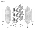
- FIG. 4 shows the arrangement state of the base material in the chamber during film formation.
- a target 20 serving as a raw material for the film 12 is disposed on a side wall of a chamber (not shown).
- the number of targets 20 is not particularly limited.
- a plurality of Ti targets and a plurality of Al targets are placed in the chamber. Can be arranged.
- a rotary table 21 is arranged at the center of a plurality of targets arranged in the chamber, and a plurality of mounting tables (substrates) 23 are arranged on the rotary table 21 by two rotary shafts 22.
- a plurality of base materials 11 are mounted on the mounting table 23.
- the number of rotating shafts 22 is not limited to that shown in FIG. 4 and can be two or more. In this case, the turntable 21 and the mounting table 23 can be increased with the increase of the rotation axis.
- the mounting table 23 is electrically connected to the negative electrode of the bias power source, the positive electrode of the bias electrode is grounded, and is electrically connected to the chamber (not shown). Further, the negative electrode of the short pulse power supply is connected to the target, and the positive electrode of the short pulse power supply is grounded (not shown).
- the coating 12 When the coating 12 is formed, an inert gas and a nitrogen gas are introduced into a vacuum chamber, and high power is applied to the target 20 with a short pulse. Thereby, plasma 30 is generated in the chamber. When ions collide with the target 20, metal atoms and metal ions jump out of the target 20 and adhere to the surface of the substrate 11 together with nitrogen atoms.
- the turntable 21 and the rotating shaft 22 are each rotating in the direction of the arrow shown in the figure.
- Pulse width 100 ⁇ s to 10 ms Pulse power density: 1.5 kW / cm 2 or more Pulse average power: 4 kW or more Bias voltage: 80 V or less Chamber pressure: 1 Pa or less Deposition time: 4 to 650 minutes.
- the pulse width is more preferably 100 ⁇ s to 1 ms, and the bias is preferably 60 V or less.
- the partial pressure of the reaction gas nitrogen gas in the present embodiment
- the partial pressure of the reaction gas preferably takes hysteresis loss into consideration.
- Sample No. 1 to 13 and A to F> (Deposition process) First, a substrate was prepared. Sample No. The base materials 1 to 8, 10 to 13 and A to F were made of cemented carbide manufactured by Sumitomo Electric Industries, and the shape was “SSEHVL4160-R10” (diameter 16 mm, 4 blades). Sample No. The base material of No. 9 was a cemented carbide alloy manufactured by Sumitomo Electric Industries, and the shape was “SSEHVL4100-R10” (diameter 10 mm, 4 blades).
- the prepared base material was placed on a mounting table (substrate) in the chamber of the HiPIMS apparatus (see FIG. 4).
- an alloy target of titanium (50 atomic%) and aluminum (50 atomic%) was placed as a target.
- argon (Ar) gas and nitrogen (N 2 ) gas a film forming process was performed under the following film forming conditions.
- the film forming conditions other than the pulse width were the same for each sample.
- Table 1 shows the pulse width of each sample.
- the film formation time was set to an appropriate time for making the film a target film thickness.
- Pulse width Pulse time: 25 ⁇ s to 50 ms (changed for each sample, see Table 1)
- Pulse average power 6kW
- Bias voltage 30-60V (changed for each sample, see Table 1)
- Chamber pressure 0.60 to 0.70
- Argon gas partial pressure 0.4 Pa
- Transition mode “Pulse power density” is a value obtained by dividing “average power in a pulse” by “the area of the racetrack on the target surface”.
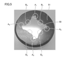
- a section 50 was obtained by partially cutting the cutting edge portion of the rotary tool using a cutting machine equipped with a diamond rotary blade.
- the obtained slice 50 is embedded in a resin 51, and the cross section of the slice 50 (the surface of the slice 50 observed in FIG. 5) is observed with an SEM, and the cutting blade portions A 1 to A
- the film thickness A of the film covering the surface of A 4 was measured, and the film thickness B of the film covering the surfaces of the grooves B 1 to B 4 was measured, and the ratio was calculated from the average value of each.
- the thickness of the coating at any one point where the deviation from the tip of the cutting edge is within 100 ⁇ m is measured on the outer periphery of the cutting edge.
- the film thickness of the coating at any one point where the deviation from the position where the line L4 and the outer periphery of the blade edge 1 are in contact is within 100 ⁇ m (see FIG. 3).
- the ratio B / A was obtained by dividing the total value of the four film thicknesses measured at the groove part by the total value of the four film thicknesses measured at the cutting edge part. The results are shown in Table 1.
- Cutting conditions Work material: Stainless steel (SUS304)
- Cutting depth ap 4.8 mm
- Rotation speed 1200 times / min
- Feeding speed 130mm / min
- Air blow Existence
- the “cutting amount ap” indicates the cutting amount in the axial direction of the rotary tool.
- Cutting conditions Work material: Stainless steel (SUS304) Cutting speed: 30 m / min Feed rate (fz): 0.083 mm / blade Cutting depth ap: 16.0 mm Cutting depth ae: 1.6 mm
- the “cutting amount ap” indicates the cutting amount in the axial direction of the rotary tool
- the “cutting amount ae” indicates the cutting amount in the radial direction.
- Cutting conditions Work material: Stainless steel (SUS304) Cutting speed: 50 m / min Feed rate (fz): 0.050 mm / blade Cutting depth ap: 10.0 mm Cutting depth ae: 1.0 mm
- the “cutting amount ap” indicates the cutting amount in the axial direction of the rotary tool
- the “cutting amount ae” indicates the cutting amount in the radial direction.
- Sample No. 14 to 16 except that the pulse power density was changed as shown in Table 2, sample No. A rotating tool (end mill) was obtained in the same manner as in No.7. Sample No. 17 to 20 except that the pulse average power was changed as shown in Table 2. A rotating tool (end mill) was obtained in the same manner as in No.7. Sample No. Samples Nos. 21 to 24 were changed except that the bias voltage was changed as shown in Table 2. A rotating tool (end mill) was obtained in the same manner as in No.7. The obtained sample No. For each of the rotating tools 14 to 24, the film thickness of the coating was measured by the same method as described above, and the ratio B / A was calculated. The results are shown in Table 2.
- the pulse power density is 1.5 kW / cm 2 or more
- the pulse average power is 4 kW or more
- the bias voltage is 80 V. It was found that it is preferable to set the following.
- Sample No. 25-31 Sample No. For Samples 25 to 31, sample Nos. Were changed except that the film formation time was changed as shown in Table 3. A rotating tool (end mill) was obtained in the same manner as in No.7. The obtained sample No. For each of the rotary tools 25 to 31, the film thickness was measured by the same method as above, and the ratio B / A was calculated. Sample No. The cutting test 1 was performed using each of the rotary tools 25 to 31, and the cutting distance until the tool life was reached was measured. These results are shown in Table 3.
- the ratio B / A was 0.8 or more when the film thickness A was 0.07 ⁇ m or more. That is, it was found that when the film thickness A of the coating was 0.07 ⁇ m or more, the ratio B / A could be easily controlled to be 0.8 or more. The same can be said when the film thickness A is 10.8 ⁇ m or less. Sample No. 7, 28 and no. It was confirmed that the cutting distance of 29 was particularly long. From this, it was found that the abrasion resistance was particularly excellent when the film thickness A of the film was 2.08 to 5.71 ⁇ m.
- Sample No. 32-41 and G Sample No. 32 to 41 and G, except that the composition of the coating was changed as shown in Table 4, Sample No. A rotating tool (end mill) was obtained in the same manner as in No.7. In addition, in order to change the composition of the coating as shown in Table 4, the type of target in the chamber and the type of introduced gas were changed as appropriate. The obtained sample No. For each of the 32 to 41 and G rotary tools, the film thickness was measured by the same method as above, and the ratio B / A was calculated. The results are shown in Table 4.
- the above-mentioned ratio B / A of the coating provided in the drill when the predetermined film forming condition is satisfied It was confirmed to be 0.8 or more.
- Sample No. with the ratio B / A of 0.8 or more was used.
- 42 is a sample No. 42. 43 and no. It was confirmed that the cutting resistance was smaller than that of No. 44 and the wear resistance was excellent.
- a substrate was prepared.
- Sample No. The base materials 45 to 49, 51 to 53, and 55 to 61 were made of cemented carbide made by Sumitomo Electric Industries, and the shape was “SSEHVL4160-R10” (diameter 16 mm, 4 blades).
- Sample No. The 50 base material was a cemented carbide manufactured by Sumitomo Electric Industries, and the shape was “SSEHVL4100-R10” (diameter 10 mm, 4 blades).
- Sample No. Regarding 45 the prepared base material was placed on a mounting table (substrate) in the chamber of the AIP apparatus. In the chamber, an alloy target of titanium (50 atomic%) and aluminum (50 atomic%) was placed as a target. Then, while introducing argon (Ar) gas and nitrogen (N 2 ) gas, a film forming process was performed under the following film forming conditions. The film formation time was set to an appropriate time for making the film a target film thickness.
- Ar argon
- N 2 nitrogen
- Sample No. Samples Nos. 46 to 54 were the same except that the arc current and / or bias voltage was changed as shown in Table 6.
- a rotary tool (end mill or drill) was obtained in the same manner as in No. 45.
- a rotating tool (end mill) was obtained in the same manner as in No. 45.
- the film thickness was measured by the same method as above, and the ratio B / A was calculated. The results are shown in Table 6.
Landscapes
- Chemical & Material Sciences (AREA)
- Engineering & Computer Science (AREA)
- Mechanical Engineering (AREA)
- Chemical Kinetics & Catalysis (AREA)
- Materials Engineering (AREA)
- Metallurgy (AREA)
- Organic Chemistry (AREA)
- Physical Vapour Deposition (AREA)
- Drilling Tools (AREA)
- Cutting Tools, Boring Holders, And Turrets (AREA)
Abstract
La présente invention vise à fournir un outil rotatif (10) ayant une résistance élevée à l'usure. L'outil rotatif (10) comporte : un matériau de base (11) comprenant des bords de coupe et des rainures (4) ; et un film (12) recouvrant la surface du matériau de base (11). Le rapport B/A de l'épaisseur B du film (12) recouvrant la surface des rainures (4) à l'épaisseur A du film (12) recouvrant la surface des bords de coupe est de 0,8 ou plus.
Priority Applications (3)
| Application Number | Priority Date | Filing Date | Title |
|---|---|---|---|
| JP2017502080A JP6973069B2 (ja) | 2015-02-23 | 2016-02-15 | 回転工具 |
| EP16755267.8A EP3263256B1 (fr) | 2015-02-23 | 2016-02-15 | Outil rotatif |
| US15/552,644 US10471523B2 (en) | 2015-02-23 | 2016-02-15 | Rotating tool |
Applications Claiming Priority (2)
| Application Number | Priority Date | Filing Date | Title |
|---|---|---|---|
| JP2015033136 | 2015-02-23 | ||
| JP2015-033136 | 2015-02-23 |
Publications (1)
| Publication Number | Publication Date |
|---|---|
| WO2016136520A1 true WO2016136520A1 (fr) | 2016-09-01 |
Family
ID=56788477
Family Applications (1)
| Application Number | Title | Priority Date | Filing Date |
|---|---|---|---|
| PCT/JP2016/054295 WO2016136520A1 (fr) | 2015-02-23 | 2016-02-15 | Outil rotatif |
Country Status (4)
| Country | Link |
|---|---|
| US (1) | US10471523B2 (fr) |
| EP (1) | EP3263256B1 (fr) |
| JP (1) | JP6973069B2 (fr) |
| WO (1) | WO2016136520A1 (fr) |
Cited By (1)
| Publication number | Priority date | Publication date | Assignee | Title |
|---|---|---|---|---|
| WO2018216256A1 (fr) * | 2017-05-23 | 2018-11-29 | 住友電気工業株式会社 | Revêtement et outil de coupe |
Families Citing this family (2)
| Publication number | Priority date | Publication date | Assignee | Title |
|---|---|---|---|---|
| JP6973069B2 (ja) | 2015-02-23 | 2021-11-24 | 住友電気工業株式会社 | 回転工具 |
| JP6717933B2 (ja) * | 2016-04-25 | 2020-07-08 | 京セラ株式会社 | インサート及び切削工具 |
Citations (4)
| Publication number | Priority date | Publication date | Assignee | Title |
|---|---|---|---|---|
| JPS6455375A (en) * | 1987-08-26 | 1989-03-02 | Nissin Electric Co Ltd | Device for projecting ion beam |
| WO2000056947A1 (fr) * | 1999-03-23 | 2000-09-28 | Sumitomo Electric Industries, Ltd. | Procede d'evaporation a arc sous vide, systeme d'evaporation a arc sous vide et outil de coupe rotatif |
| JP2005022071A (ja) * | 2003-07-04 | 2005-01-27 | Tungaloy Corp | 硬質膜被覆ドリル |
| JP2013184271A (ja) * | 2012-03-09 | 2013-09-19 | Mitsubishi Materials Corp | 硬質被覆層がすぐれた耐摩耗性と耐欠損性を維持する表面被覆切削工具 |
Family Cites Families (20)
| Publication number | Priority date | Publication date | Assignee | Title |
|---|---|---|---|---|
| JPS57184616A (en) | 1981-05-07 | 1982-11-13 | Nachi Fujikoshi Corp | Drill |
| JPS5890413A (ja) | 1981-11-18 | 1983-05-30 | Nachi Fujikoshi Corp | エンドミル |
| JPS61124314U (fr) | 1985-01-19 | 1986-08-05 | ||
| JPS61288914A (ja) * | 1985-06-14 | 1986-12-19 | Sumitomo Electric Ind Ltd | 表面被覆エンドミル |
| DE3527948A1 (de) | 1985-08-03 | 1987-02-12 | Hawera Praezisionswerkzeuge | Verfahren zur herstellung von werkzeugen mit beschichteter spannut wie bohrern, fraesern o. dgl. |
| JPH04210315A (ja) * | 1990-08-10 | 1992-07-31 | Nachi Fujikoshi Corp | 回転切削工具 |
| US5467670A (en) * | 1994-08-15 | 1995-11-21 | General Motors Corporation | Method of manufacture for rotary cutting tool |
| DE19905735A1 (de) * | 1999-02-11 | 2000-08-17 | Kennametal Inc | Verfahren zum Herstellen eines Zerspanungswerkzeugs sowie Zerspanungswerkzeug |
| JP2002144125A (ja) | 2000-08-31 | 2002-05-21 | Mitsubishi Materials Corp | 穴明け工具 |
| JP2003311524A (ja) * | 2002-04-18 | 2003-11-05 | Nachi Fujikoshi Corp | 超硬ボールエンドミル |
| JP4344524B2 (ja) * | 2003-03-20 | 2009-10-14 | 京セラ株式会社 | エンドミルの製造方法 |
| KR101225803B1 (ko) * | 2004-04-13 | 2013-01-23 | 스미또모 덴꼬오 하드메탈 가부시끼가이샤 | 표면 피복 절삭 공구 |
| JP2006082206A (ja) | 2004-09-17 | 2006-03-30 | Sumitomo Electric Hardmetal Corp | 被覆ドリルの刃先再生方法 |
| JP2006152424A (ja) * | 2004-12-01 | 2006-06-15 | Osg Corp | 硬質被膜および硬質被膜被覆加工工具 |
| US20080267726A1 (en) * | 2005-07-20 | 2008-10-30 | Norihiro Masuda | Drill |
| DE102006042226A1 (de) * | 2006-09-06 | 2008-03-27 | Günther & Co. GmbH | Beschichteter Spiralbohrer |
| JP5348223B2 (ja) | 2011-11-08 | 2013-11-20 | 株式会社タンガロイ | 被覆部材 |
| JP6024981B2 (ja) * | 2012-03-09 | 2016-11-16 | 三菱マテリアル株式会社 | 高速断続切削加工で硬質被覆層がすぐれた耐チッピング性を発揮する表面被覆切削工具 |
| US9017809B2 (en) * | 2013-01-25 | 2015-04-28 | Kennametal Inc. | Coatings for cutting tools |
| JP6973069B2 (ja) | 2015-02-23 | 2021-11-24 | 住友電気工業株式会社 | 回転工具 |
-
2016
- 2016-02-15 JP JP2017502080A patent/JP6973069B2/ja active Active
- 2016-02-15 US US15/552,644 patent/US10471523B2/en active Active
- 2016-02-15 EP EP16755267.8A patent/EP3263256B1/fr active Active
- 2016-02-15 WO PCT/JP2016/054295 patent/WO2016136520A1/fr active Application Filing
Patent Citations (4)
| Publication number | Priority date | Publication date | Assignee | Title |
|---|---|---|---|---|
| JPS6455375A (en) * | 1987-08-26 | 1989-03-02 | Nissin Electric Co Ltd | Device for projecting ion beam |
| WO2000056947A1 (fr) * | 1999-03-23 | 2000-09-28 | Sumitomo Electric Industries, Ltd. | Procede d'evaporation a arc sous vide, systeme d'evaporation a arc sous vide et outil de coupe rotatif |
| JP2005022071A (ja) * | 2003-07-04 | 2005-01-27 | Tungaloy Corp | 硬質膜被覆ドリル |
| JP2013184271A (ja) * | 2012-03-09 | 2013-09-19 | Mitsubishi Materials Corp | 硬質被覆層がすぐれた耐摩耗性と耐欠損性を維持する表面被覆切削工具 |
Non-Patent Citations (1)
| Title |
|---|
| See also references of EP3263256A4 * |
Cited By (2)
| Publication number | Priority date | Publication date | Assignee | Title |
|---|---|---|---|---|
| WO2018216256A1 (fr) * | 2017-05-23 | 2018-11-29 | 住友電気工業株式会社 | Revêtement et outil de coupe |
| JPWO2018216256A1 (ja) * | 2017-05-23 | 2020-03-26 | 住友電気工業株式会社 | 被膜および切削工具 |
Also Published As
| Publication number | Publication date |
|---|---|
| US20180029145A1 (en) | 2018-02-01 |
| JPWO2016136520A1 (ja) | 2017-11-30 |
| EP3263256A4 (fr) | 2018-06-27 |
| US10471523B2 (en) | 2019-11-12 |
| EP3263256B1 (fr) | 2019-07-31 |
| EP3263256A1 (fr) | 2018-01-03 |
| JP6973069B2 (ja) | 2021-11-24 |
Similar Documents
| Publication | Publication Date | Title |
|---|---|---|
| US11872636B2 (en) | Surface-coated cutting tool and method for manufacturing same | |
| JP5008984B2 (ja) | 表面被覆切削工具および表面被覆切削工具の製造方法 | |
| JP2011067883A (ja) | 表面被覆切削工具 | |
| JP2019528183A (ja) | 多層硬質皮膜被覆切削工具 | |
| JP5286625B2 (ja) | 表面被覆切削工具およびその製造方法 | |
| WO2016136520A1 (fr) | Outil rotatif | |
| JP6331003B2 (ja) | 表面被覆切削工具 | |
| JP5315526B2 (ja) | 表面被覆切削工具 | |
| JP2010076084A (ja) | 表面被覆切削工具 | |
| JP2009285760A (ja) | 切削工具 | |
| JP5483071B2 (ja) | 表面被覆切削工具 | |
| JP6666431B2 (ja) | 硬質被膜および切削工具 | |
| JP2010115739A (ja) | 表面被覆切削工具 | |
| JP5267985B2 (ja) | 表面被覆切削工具 | |
| JP2010076082A (ja) | 表面被覆切削工具 | |
| CN114799286B (zh) | 钻头 | |
| JP2005022071A (ja) | 硬質膜被覆ドリル | |
| WO2023191049A1 (fr) | Outil revêtu et outil de coupe | |
| WO2024048672A1 (fr) | Outil revêtu, et outil de coupe | |
| JP5267986B2 (ja) | 表面被覆切削工具 | |
| JP4720993B2 (ja) | 難削材の高速重切削加工で硬質被覆層がすぐれた耐チッピング性を発揮する表面被覆高速度工具鋼製切削工具 | |
| JP4158191B2 (ja) | 高速重切削条件ですぐれた耐チッピング性および耐摩耗性を発揮する硬質被覆層を切削工具表面に形成する方法 | |
| JP2006015451A (ja) | 高速切削加工で硬質被覆層がすぐれた耐摩耗性を発揮する表面被覆超硬合金製切削工具の製造方法 | |
| WO2020039736A1 (fr) | Outil de coupe | |
| JP2022139719A (ja) | 表面被覆切削工具 |
Legal Events
| Date | Code | Title | Description |
|---|---|---|---|
| 121 | Ep: the epo has been informed by wipo that ep was designated in this application |
Ref document number: 16755267 Country of ref document: EP Kind code of ref document: A1 |
|
| ENP | Entry into the national phase |
Ref document number: 2017502080 Country of ref document: JP Kind code of ref document: A |
|
| REEP | Request for entry into the european phase |
Ref document number: 2016755267 Country of ref document: EP |
|
| NENP | Non-entry into the national phase |
Ref country code: DE |