WO2016136520A1 - Rotating tool - Google Patents
Rotating tool Download PDFInfo
- Publication number
- WO2016136520A1 WO2016136520A1 PCT/JP2016/054295 JP2016054295W WO2016136520A1 WO 2016136520 A1 WO2016136520 A1 WO 2016136520A1 JP 2016054295 W JP2016054295 W JP 2016054295W WO 2016136520 A1 WO2016136520 A1 WO 2016136520A1
- Authority
- WO
- WIPO (PCT)
- Prior art keywords
- rotary tool
- cutting
- film
- coating
- film thickness
- Prior art date
Links
Images


Classifications
-
- B—PERFORMING OPERATIONS; TRANSPORTING
- B23—MACHINE TOOLS; METAL-WORKING NOT OTHERWISE PROVIDED FOR
- B23C—MILLING
- B23C5/00—Milling-cutters
- B23C5/16—Milling-cutters characterised by physical features other than shape
-
- B—PERFORMING OPERATIONS; TRANSPORTING
- B23—MACHINE TOOLS; METAL-WORKING NOT OTHERWISE PROVIDED FOR
- B23B—TURNING; BORING
- B23B51/00—Tools for drilling machines
-
- B—PERFORMING OPERATIONS; TRANSPORTING
- B23—MACHINE TOOLS; METAL-WORKING NOT OTHERWISE PROVIDED FOR
- B23B—TURNING; BORING
- B23B51/00—Tools for drilling machines
- B23B51/02—Twist drills
-
- B—PERFORMING OPERATIONS; TRANSPORTING
- B23—MACHINE TOOLS; METAL-WORKING NOT OTHERWISE PROVIDED FOR
- B23C—MILLING
- B23C5/00—Milling-cutters
- B23C5/02—Milling-cutters characterised by the shape of the cutter
- B23C5/10—Shank-type cutters, i.e. with an integral shaft
-
- B—PERFORMING OPERATIONS; TRANSPORTING
- B23—MACHINE TOOLS; METAL-WORKING NOT OTHERWISE PROVIDED FOR
- B23D—PLANING; SLOTTING; SHEARING; BROACHING; SAWING; FILING; SCRAPING; LIKE OPERATIONS FOR WORKING METAL BY REMOVING MATERIAL, NOT OTHERWISE PROVIDED FOR
- B23D77/00—Reaming tools
-
- C—CHEMISTRY; METALLURGY
- C23—COATING METALLIC MATERIAL; COATING MATERIAL WITH METALLIC MATERIAL; CHEMICAL SURFACE TREATMENT; DIFFUSION TREATMENT OF METALLIC MATERIAL; COATING BY VACUUM EVAPORATION, BY SPUTTERING, BY ION IMPLANTATION OR BY CHEMICAL VAPOUR DEPOSITION, IN GENERAL; INHIBITING CORROSION OF METALLIC MATERIAL OR INCRUSTATION IN GENERAL
- C23C—COATING METALLIC MATERIAL; COATING MATERIAL WITH METALLIC MATERIAL; SURFACE TREATMENT OF METALLIC MATERIAL BY DIFFUSION INTO THE SURFACE, BY CHEMICAL CONVERSION OR SUBSTITUTION; COATING BY VACUUM EVAPORATION, BY SPUTTERING, BY ION IMPLANTATION OR BY CHEMICAL VAPOUR DEPOSITION, IN GENERAL
- C23C14/00—Coating by vacuum evaporation, by sputtering or by ion implantation of the coating forming material
- C23C14/06—Coating by vacuum evaporation, by sputtering or by ion implantation of the coating forming material characterised by the coating material
- C23C14/0641—Nitrides
-
- C—CHEMISTRY; METALLURGY
- C23—COATING METALLIC MATERIAL; COATING MATERIAL WITH METALLIC MATERIAL; CHEMICAL SURFACE TREATMENT; DIFFUSION TREATMENT OF METALLIC MATERIAL; COATING BY VACUUM EVAPORATION, BY SPUTTERING, BY ION IMPLANTATION OR BY CHEMICAL VAPOUR DEPOSITION, IN GENERAL; INHIBITING CORROSION OF METALLIC MATERIAL OR INCRUSTATION IN GENERAL
- C23C—COATING METALLIC MATERIAL; COATING MATERIAL WITH METALLIC MATERIAL; SURFACE TREATMENT OF METALLIC MATERIAL BY DIFFUSION INTO THE SURFACE, BY CHEMICAL CONVERSION OR SUBSTITUTION; COATING BY VACUUM EVAPORATION, BY SPUTTERING, BY ION IMPLANTATION OR BY CHEMICAL VAPOUR DEPOSITION, IN GENERAL
- C23C14/00—Coating by vacuum evaporation, by sputtering or by ion implantation of the coating forming material
- C23C14/22—Coating by vacuum evaporation, by sputtering or by ion implantation of the coating forming material characterised by the process of coating
- C23C14/34—Sputtering
- C23C14/3485—Sputtering using pulsed power to the target
-
- C—CHEMISTRY; METALLURGY
- C23—COATING METALLIC MATERIAL; COATING MATERIAL WITH METALLIC MATERIAL; CHEMICAL SURFACE TREATMENT; DIFFUSION TREATMENT OF METALLIC MATERIAL; COATING BY VACUUM EVAPORATION, BY SPUTTERING, BY ION IMPLANTATION OR BY CHEMICAL VAPOUR DEPOSITION, IN GENERAL; INHIBITING CORROSION OF METALLIC MATERIAL OR INCRUSTATION IN GENERAL
- C23C—COATING METALLIC MATERIAL; COATING MATERIAL WITH METALLIC MATERIAL; SURFACE TREATMENT OF METALLIC MATERIAL BY DIFFUSION INTO THE SURFACE, BY CHEMICAL CONVERSION OR SUBSTITUTION; COATING BY VACUUM EVAPORATION, BY SPUTTERING, BY ION IMPLANTATION OR BY CHEMICAL VAPOUR DEPOSITION, IN GENERAL
- C23C14/00—Coating by vacuum evaporation, by sputtering or by ion implantation of the coating forming material
- C23C14/22—Coating by vacuum evaporation, by sputtering or by ion implantation of the coating forming material characterised by the process of coating
- C23C14/34—Sputtering
- C23C14/35—Sputtering by application of a magnetic field, e.g. magnetron sputtering
-
- C—CHEMISTRY; METALLURGY
- C23—COATING METALLIC MATERIAL; COATING MATERIAL WITH METALLIC MATERIAL; CHEMICAL SURFACE TREATMENT; DIFFUSION TREATMENT OF METALLIC MATERIAL; COATING BY VACUUM EVAPORATION, BY SPUTTERING, BY ION IMPLANTATION OR BY CHEMICAL VAPOUR DEPOSITION, IN GENERAL; INHIBITING CORROSION OF METALLIC MATERIAL OR INCRUSTATION IN GENERAL
- C23C—COATING METALLIC MATERIAL; COATING MATERIAL WITH METALLIC MATERIAL; SURFACE TREATMENT OF METALLIC MATERIAL BY DIFFUSION INTO THE SURFACE, BY CHEMICAL CONVERSION OR SUBSTITUTION; COATING BY VACUUM EVAPORATION, BY SPUTTERING, BY ION IMPLANTATION OR BY CHEMICAL VAPOUR DEPOSITION, IN GENERAL
- C23C30/00—Coating with metallic material characterised only by the composition of the metallic material, i.e. not characterised by the coating process
- C23C30/005—Coating with metallic material characterised only by the composition of the metallic material, i.e. not characterised by the coating process on hard metal substrates
-
- B—PERFORMING OPERATIONS; TRANSPORTING
- B23—MACHINE TOOLS; METAL-WORKING NOT OTHERWISE PROVIDED FOR
- B23B—TURNING; BORING
- B23B2228/00—Properties of materials of tools or workpieces, materials of tools or workpieces applied in a specific manner
- B23B2228/10—Coatings
- B23B2228/105—Coatings with specified thickness
-
- B—PERFORMING OPERATIONS; TRANSPORTING
- B23—MACHINE TOOLS; METAL-WORKING NOT OTHERWISE PROVIDED FOR
- B23C—MILLING
- B23C2210/00—Details of milling cutters
- B23C2210/40—Flutes, i.e. chip conveying grooves
-
- B—PERFORMING OPERATIONS; TRANSPORTING
- B23—MACHINE TOOLS; METAL-WORKING NOT OTHERWISE PROVIDED FOR
- B23C—MILLING
- B23C2224/00—Materials of tools or workpieces composed of a compound including a metal
-
- B—PERFORMING OPERATIONS; TRANSPORTING
- B23—MACHINE TOOLS; METAL-WORKING NOT OTHERWISE PROVIDED FOR
- B23C—MILLING
- B23C2228/00—Properties of materials of tools or workpieces, materials of tools or workpieces applied in a specific manner
- B23C2228/10—Coating
Definitions
- the present invention relates to a rotary tool including a base material and a film formed on the base material.
- a tool in which a hard film such as TiAlN is provided on the surface of a hard base material such as a WC-based cemented carbide is known.
- a hard film such as TiAlN
- a hard base material such as a WC-based cemented carbide
- Non-Patent Document 1 discloses a tool in which a coating is provided on the surface of a substrate by an arc ion plating (AIP) method.
- AIP arc ion plating
- MS magnetron sputtering
- the degree of improvement in wear resistance by providing the coating may be insufficient.
- the present disclosure aims to provide a rotary tool having excellent wear resistance.
- the rotary tool which concerns on 1 aspect of this invention is equipped with the base material containing a cutting blade part and a groove part, and the film which coat
- the ratio B / A of the film thickness B of the coating covering the surface of the groove is 0.8 or more.
- FIG. 2 is a cross-sectional view taken along the line XX shown in FIG. It is a schematic diagram for demonstrating each area
- the present inventors have found that in the conventional rotary tool, the thickness of the coating formed on the surface of the groove is smaller than the thickness of the coating formed on the surface of the cutting edge. It was found that the film thickness was remarkably small, and this was due to a decrease in wear resistance of the rotary tool. Based on this knowledge, the present inventors consider that there is a problem with conventional film formation methods such as AIP method and MS method, and as an alternative formation method, J. Mater. Res., Vol. 27, No. 5 (2012), 780-792 (Non-patent Document 2), the High Power Impulse Magnetron Sputtering (HiPIMS) method has been studied earnestly. As a result, a rotating tool having excellent wear resistance was completed.
- a rotary tool includes a base material including a cutting edge portion and a groove portion, and a coating that covers the surface of the base material, and a coating that covers the surface of the cutting edge portion.
- the ratio B / A of the film thickness B of the film covering the surface of the groove to the film thickness A is 0.8 or more.
- the rotary tool described above since the wear of the coating covering the surface of the groove can be suppressed, it can have excellent wear resistance.
- the rotary tool is an end mill. Conventionally, in the end mill, the above ratio tended to be particularly small. However, according to the rotary tool, since the ratio can be larger than the conventional one, it is possible to have excellent wear resistance.
- the rotating tool is a drill.
- the ratio tends to be particularly small.
- the ratio can be higher than that of the conventional one, it is possible to have excellent wear resistance.
- the ratio B / A is 1 or more. Thereby, it can be further excellent in wear resistance.
- the film thickness A is 0.1 ⁇ m or more and 10 ⁇ m or less. Thereby, it can be further excellent in wear resistance.
- the film thickness A is 2.0 ⁇ m or more and 6.0 ⁇ m or less. Thereby, it can be further excellent in wear resistance.
- the material of the coating is at least one element selected from the group consisting of Group 4 elements, Group 5 elements, Group 6 elements, aluminum and silicon in the periodic table, boron, One or more compounds composed of at least one element selected from the group consisting of carbon, nitrogen and oxygen.
- the said rotary tool can be provided with the film which has high hardness.
- the present embodiment an embodiment of the present invention (hereinafter referred to as “the present embodiment”) will be described in detail, but the present embodiment is not limited thereto.
- FIG. 1 is a schematic plan view showing an example of a rotary tool according to the present embodiment
- FIG. 2 is a cross-sectional view taken along line XX shown in FIG.
- a four-blade end mill is exemplified.
- the rotary tool 10 includes a base material 11 that is a main body of the rotary tool 10 and a coating 12 that covers the surface of the base material 11.
- the entire surface of the base material 11 constituting the rotary tool 10 may be covered with the coating 12, or a part of the base 11 may be covered.
- the surface of the base material 11 constituting the shank 2 may not be covered but only the surface of the base material constituting the cutting edge 1 may be covered with the coating 12.
- an end mill is illustrated as the rotary tool 10, but a drill can be used in addition to the end mill.
- the rotary tool 10 includes a base material 11 having at least a cutting edge portion for cutting out the work material in contact with the work material, a groove portion for discharging chips, and a coating 12.
- a router, a reamer, etc. can be mentioned besides the above.
- the rotary tool 10 of this embodiment can be suitably used as a rotary tool for high-precision machining.
- the base material 11 is a main body in the shape of the rotary tool 10.
- the base material 11 includes a blade edge 1 and a shank 2.
- the blade edge 1 includes an outer peripheral blade portion 3, a groove portion 4, and a bottom blade portion 5.
- the outer peripheral blade portion 3 and the bottom blade portion 5 are portions for cutting out the work material
- the groove portion 4 is a portion for discharging chips generated by cutting to the outside.
- the outer peripheral blade portion 3 includes a cutting edge portion (not shown) that becomes a portion having no clearance angle with respect to the work material.
- the cutting edge portion is a portion that comes into contact with the work material during cutting.
- region of the outer periphery blade part 3 and the groove part 4 is determined as follows.
- circle S is a virtual circle that includes the cross section of blade edge 1 inside and is drawn by connecting blade edge tip 3 a, and its diameter is D.
- the cutting edge tip 3a is a portion serving as a starting point for cutting out the work material.
- Circle S1 is a virtual circle having a contact point between cutting edge tip 3a and circle S as a center point and radius D1 of 2 / 10D.
- an area located within the virtual circle S ⁇ b> 1 is defined as the outer peripheral blade portion 3.
- Lines L1 and L2 are virtual lines that connect adjacent cutting edge tips 3a and the center point P of the circle S.
- the line L3 is a virtual line that equally divides the angle 2 ⁇ formed by the line L1 and the line L2.
- the circle S2 is a virtual circle whose center point is the contact point between the line L3 and the outer periphery of the substrate 11, and whose radius D2 is 1 / 10D.
- a region located within the virtual circle S2 (including the circle S2) in the outer periphery of the base material 11 is defined as the groove portion 4.
- the base material 11 of the rotary tool As the material of the base material 11, a conventionally known material known as the base material 11 of the rotary tool can be used without any particular limitation. Examples thereof include tungsten carbide (WC) based cemented carbide, cermet, high speed steel, ceramics, cubic boron nitride sintered body, diamond sintered body, and the like. In addition, the base material 11 may be integrally formed, and what combined several components may be used.
- WC tungsten carbide
- the coating 12 covers all or part of the surface of the substrate 11.
- the coating 12 may be a single layer composed of one layer or a multilayer composed of two or more layers.
- the ratio B / A of the film thickness B of the coating 12 covering the surface of the groove 4 to the film thickness A of the coating 12 covering the surface of the cutting edge 6 is 0.8 or more.
- the rotary tool 10 of the present embodiment is excellent in wear resistance
- the rotary tool not only the physical properties of the base material but also the wear resistance expected in design is derived from the physical properties of the coating provided on the surface.
- conventional rotary tools tend not to exhibit the wear resistance as expected in design.
- the ratio B / A of the film thickness B of the coating formed on the surface of the groove to the film thickness A of the coating formed on the surface of the cutting edge is 0. It was found that the wear resistance of the rotary tool was insufficient as a result because the wear resistance of the groove was lower than expected in the design due to being too small, about 5 or less.
- the above ratio is too small because the coating of the conventional rotary tool is manufactured by the MS method or the AIP method.
- the MS method since the ionization rate of atoms serving as targets in the plasma is too low, ions cannot be sufficiently drawn into the groove due to the substrate bias.
- the ionization rate is sufficient in the AIP method, it is necessary to increase the pressure in the chamber in order to reduce the number of metal droplets generated from the target. Thereby, since the pressure in the chamber becomes too high, the mean free path of ions tends to be too short. If the mean free path of ions is short, ions are likely to be scattered, and therefore it becomes difficult to draw ions into the groove. For this reason, in these methods, it is not possible to form a film with a uniform film thickness on the surface of the base material for a rotary tool having a complicated shape as compared with other tools. The film thickness B at the groove located in the intricate portion is reduced.
- the film thickness B is small, the groove will advance faster than expected. Thereby, since the smoothness of a groove part falls and chip
- the rotary tool 10 of this embodiment includes a coating 12 formed by using the HiPIMS method instead of the MS method and the AIP method.
- the HiPIMS method applies high power to the target in a short pulse, so that a high ionization rate can be achieved, and the method is a kind of sputtering method, so the pressure in the chamber can be lowered. It is.
- the coating film 12 having a uniform film thickness is formed on the surface of the substrate 11, and the ratio B / A can show a high value of 0.8 or more. Therefore, since the rotary tool 10 of the present embodiment can solve the above-mentioned problems that the conventional rotary tool has, the rotary tool 10 of the present embodiment has higher wear resistance than the conventional one. be able to. Furthermore, since it has a high wear resistance, it can have a long life, and the cutting accuracy is also improved, so that the surface condition such as the surface roughness of the work material can be improved.
- the rotary tool 10 of this embodiment is suitable as a rotary tool for high-precision machining.
- the film thickness A and the film thickness B of the coating 12 can be measured by cutting the rotary tool 10 in the longitudinal direction (lateral direction in FIG. 1) and observing the cross section with a scanning electron microscope (SEM).
- SEM scanning electron microscope
- the film thickness A at arbitrary points (total of four places in this embodiment) of each cutting edge is measured, and the film thickness B of arbitrary points (total of four places in this embodiment) of each groove portion. Is obtained by dividing the total value of all the values of the measured film thickness B by the total value of all the values of the measured film thickness A as the ratio B / A.
- FIG. 3 for example, when the rotary tool 10 has four blades and the diameter of the cutting edge (the diameter of the circle S in FIG.
- the arbitrary point of the cutting edge is the center of the circle S1 (the cutting edge).
- the deviation from the tip 3a) is preferably within 100 ⁇ m, and any point of the groove is preferably within 100 ⁇ m from the center of the circle S2.
- the ratio B / A is preferably 1 or more.
- the rotary tool 10 can be more excellent in wear resistance.
- the wear resistance is further improved when the ratio B / A is more than 1.0, specifically, 1.01 or more. It has also been confirmed that the ratio B / A is preferably 4.15 or less. Further, when the ratio B / A is 1.05 to 3.90, the wear resistance is particularly excellent, and when the ratio B / A is 1.22 to 3.90, the wear resistance is more remarkable. It has also been confirmed to be excellent.
- the film thickness A is preferably 0.1 ⁇ m or more and 10 ⁇ m or less (hereinafter, this notation is also simply expressed as “0.1 to 10 ⁇ m”).
- the film thickness A is more preferably 2.0 to 6.0 ⁇ m.
- a conventionally known material known as the coating 12 of the rotary tool can be used without any particular limitation.
- Group 4 elements Ti, Zr, Hf, etc.
- Group 5 elements V, Nb, Ta, etc.
- Group 6 elements Cr, Mo, W, etc.
- aluminum (Al) and silicon in the periodic table From at least one element selected from the group consisting of (Si) and at least one element selected from the group consisting of boron (B), carbon (C), nitrogen (N) and oxygen (O) It is preferable that it is 1 or more types of compounds which become.
- TiAlN, TiN, CrN, AlCrN, AlCrSiN, TiAlSiN, TiSiN, TiCN, TiAlON, and TiAlBNO are preferable, and TiAlN, TiN, CrN, AlCrN, AlCrSiN, TiAlSiN, and TiCN are more preferable.
- the atomic ratio is not limited to those in the stoichiometric range unless the atomic ratio is particularly limited. .
- the rotary tool 10 of this embodiment can be manufactured by forming the film 12 on the surface of the base material 11 using the HiPIMS method.
- the film which consists of TiAlN is formed as an example of the film 12 is demonstrated using FIG.
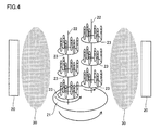
- FIG. 4 shows the arrangement state of the base material in the chamber during film formation.
- a target 20 serving as a raw material for the film 12 is disposed on a side wall of a chamber (not shown).
- the number of targets 20 is not particularly limited.
- a plurality of Ti targets and a plurality of Al targets are placed in the chamber. Can be arranged.
- a rotary table 21 is arranged at the center of a plurality of targets arranged in the chamber, and a plurality of mounting tables (substrates) 23 are arranged on the rotary table 21 by two rotary shafts 22.
- a plurality of base materials 11 are mounted on the mounting table 23.
- the number of rotating shafts 22 is not limited to that shown in FIG. 4 and can be two or more. In this case, the turntable 21 and the mounting table 23 can be increased with the increase of the rotation axis.
- the mounting table 23 is electrically connected to the negative electrode of the bias power source, the positive electrode of the bias electrode is grounded, and is electrically connected to the chamber (not shown). Further, the negative electrode of the short pulse power supply is connected to the target, and the positive electrode of the short pulse power supply is grounded (not shown).
- the coating 12 When the coating 12 is formed, an inert gas and a nitrogen gas are introduced into a vacuum chamber, and high power is applied to the target 20 with a short pulse. Thereby, plasma 30 is generated in the chamber. When ions collide with the target 20, metal atoms and metal ions jump out of the target 20 and adhere to the surface of the substrate 11 together with nitrogen atoms.
- the turntable 21 and the rotating shaft 22 are each rotating in the direction of the arrow shown in the figure.
- Pulse width 100 ⁇ s to 10 ms Pulse power density: 1.5 kW / cm 2 or more Pulse average power: 4 kW or more Bias voltage: 80 V or less Chamber pressure: 1 Pa or less Deposition time: 4 to 650 minutes.
- the pulse width is more preferably 100 ⁇ s to 1 ms, and the bias is preferably 60 V or less.
- the partial pressure of the reaction gas nitrogen gas in the present embodiment
- the partial pressure of the reaction gas preferably takes hysteresis loss into consideration.
- Sample No. 1 to 13 and A to F> (Deposition process) First, a substrate was prepared. Sample No. The base materials 1 to 8, 10 to 13 and A to F were made of cemented carbide manufactured by Sumitomo Electric Industries, and the shape was “SSEHVL4160-R10” (diameter 16 mm, 4 blades). Sample No. The base material of No. 9 was a cemented carbide alloy manufactured by Sumitomo Electric Industries, and the shape was “SSEHVL4100-R10” (diameter 10 mm, 4 blades).
- the prepared base material was placed on a mounting table (substrate) in the chamber of the HiPIMS apparatus (see FIG. 4).
- an alloy target of titanium (50 atomic%) and aluminum (50 atomic%) was placed as a target.
- argon (Ar) gas and nitrogen (N 2 ) gas a film forming process was performed under the following film forming conditions.
- the film forming conditions other than the pulse width were the same for each sample.
- Table 1 shows the pulse width of each sample.
- the film formation time was set to an appropriate time for making the film a target film thickness.
- Pulse width Pulse time: 25 ⁇ s to 50 ms (changed for each sample, see Table 1)
- Pulse average power 6kW
- Bias voltage 30-60V (changed for each sample, see Table 1)
- Chamber pressure 0.60 to 0.70
- Argon gas partial pressure 0.4 Pa
- Transition mode “Pulse power density” is a value obtained by dividing “average power in a pulse” by “the area of the racetrack on the target surface”.
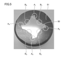
- a section 50 was obtained by partially cutting the cutting edge portion of the rotary tool using a cutting machine equipped with a diamond rotary blade.
- the obtained slice 50 is embedded in a resin 51, and the cross section of the slice 50 (the surface of the slice 50 observed in FIG. 5) is observed with an SEM, and the cutting blade portions A 1 to A
- the film thickness A of the film covering the surface of A 4 was measured, and the film thickness B of the film covering the surfaces of the grooves B 1 to B 4 was measured, and the ratio was calculated from the average value of each.
- the thickness of the coating at any one point where the deviation from the tip of the cutting edge is within 100 ⁇ m is measured on the outer periphery of the cutting edge.
- the film thickness of the coating at any one point where the deviation from the position where the line L4 and the outer periphery of the blade edge 1 are in contact is within 100 ⁇ m (see FIG. 3).
- the ratio B / A was obtained by dividing the total value of the four film thicknesses measured at the groove part by the total value of the four film thicknesses measured at the cutting edge part. The results are shown in Table 1.
- Cutting conditions Work material: Stainless steel (SUS304)
- Cutting depth ap 4.8 mm
- Rotation speed 1200 times / min
- Feeding speed 130mm / min
- Air blow Existence
- the “cutting amount ap” indicates the cutting amount in the axial direction of the rotary tool.
- Cutting conditions Work material: Stainless steel (SUS304) Cutting speed: 30 m / min Feed rate (fz): 0.083 mm / blade Cutting depth ap: 16.0 mm Cutting depth ae: 1.6 mm
- the “cutting amount ap” indicates the cutting amount in the axial direction of the rotary tool
- the “cutting amount ae” indicates the cutting amount in the radial direction.
- Cutting conditions Work material: Stainless steel (SUS304) Cutting speed: 50 m / min Feed rate (fz): 0.050 mm / blade Cutting depth ap: 10.0 mm Cutting depth ae: 1.0 mm
- the “cutting amount ap” indicates the cutting amount in the axial direction of the rotary tool
- the “cutting amount ae” indicates the cutting amount in the radial direction.
- Sample No. 14 to 16 except that the pulse power density was changed as shown in Table 2, sample No. A rotating tool (end mill) was obtained in the same manner as in No.7. Sample No. 17 to 20 except that the pulse average power was changed as shown in Table 2. A rotating tool (end mill) was obtained in the same manner as in No.7. Sample No. Samples Nos. 21 to 24 were changed except that the bias voltage was changed as shown in Table 2. A rotating tool (end mill) was obtained in the same manner as in No.7. The obtained sample No. For each of the rotating tools 14 to 24, the film thickness of the coating was measured by the same method as described above, and the ratio B / A was calculated. The results are shown in Table 2.
- the pulse power density is 1.5 kW / cm 2 or more
- the pulse average power is 4 kW or more
- the bias voltage is 80 V. It was found that it is preferable to set the following.
- Sample No. 25-31 Sample No. For Samples 25 to 31, sample Nos. Were changed except that the film formation time was changed as shown in Table 3. A rotating tool (end mill) was obtained in the same manner as in No.7. The obtained sample No. For each of the rotary tools 25 to 31, the film thickness was measured by the same method as above, and the ratio B / A was calculated. Sample No. The cutting test 1 was performed using each of the rotary tools 25 to 31, and the cutting distance until the tool life was reached was measured. These results are shown in Table 3.
- the ratio B / A was 0.8 or more when the film thickness A was 0.07 ⁇ m or more. That is, it was found that when the film thickness A of the coating was 0.07 ⁇ m or more, the ratio B / A could be easily controlled to be 0.8 or more. The same can be said when the film thickness A is 10.8 ⁇ m or less. Sample No. 7, 28 and no. It was confirmed that the cutting distance of 29 was particularly long. From this, it was found that the abrasion resistance was particularly excellent when the film thickness A of the film was 2.08 to 5.71 ⁇ m.
- Sample No. 32-41 and G Sample No. 32 to 41 and G, except that the composition of the coating was changed as shown in Table 4, Sample No. A rotating tool (end mill) was obtained in the same manner as in No.7. In addition, in order to change the composition of the coating as shown in Table 4, the type of target in the chamber and the type of introduced gas were changed as appropriate. The obtained sample No. For each of the 32 to 41 and G rotary tools, the film thickness was measured by the same method as above, and the ratio B / A was calculated. The results are shown in Table 4.
- the above-mentioned ratio B / A of the coating provided in the drill when the predetermined film forming condition is satisfied It was confirmed to be 0.8 or more.
- Sample No. with the ratio B / A of 0.8 or more was used.
- 42 is a sample No. 42. 43 and no. It was confirmed that the cutting resistance was smaller than that of No. 44 and the wear resistance was excellent.
- a substrate was prepared.
- Sample No. The base materials 45 to 49, 51 to 53, and 55 to 61 were made of cemented carbide made by Sumitomo Electric Industries, and the shape was “SSEHVL4160-R10” (diameter 16 mm, 4 blades).
- Sample No. The 50 base material was a cemented carbide manufactured by Sumitomo Electric Industries, and the shape was “SSEHVL4100-R10” (diameter 10 mm, 4 blades).
- Sample No. Regarding 45 the prepared base material was placed on a mounting table (substrate) in the chamber of the AIP apparatus. In the chamber, an alloy target of titanium (50 atomic%) and aluminum (50 atomic%) was placed as a target. Then, while introducing argon (Ar) gas and nitrogen (N 2 ) gas, a film forming process was performed under the following film forming conditions. The film formation time was set to an appropriate time for making the film a target film thickness.
- Ar argon
- N 2 nitrogen
- Sample No. Samples Nos. 46 to 54 were the same except that the arc current and / or bias voltage was changed as shown in Table 6.
- a rotary tool (end mill or drill) was obtained in the same manner as in No. 45.
- a rotating tool (end mill) was obtained in the same manner as in No. 45.
- the film thickness was measured by the same method as above, and the ratio B / A was calculated. The results are shown in Table 6.
Abstract
The purpose of the present invention is to provide a rotating tool (10) having high resistance to wear. The rotating tool (10) is provided with: a base material (11) including cutting edges and grooves (4); and a film (12) covering the surface of the base material (11). The ratio B/A of the thickness B of the film (12) covering the surface of the grooves (4) to the thickness A of the film (12) covering the surface of the cutting edges is 0.8 or higher.
Description
本発明は、基材と、該基材上に形成された被膜とを備える回転工具に関するものである。
The present invention relates to a rotary tool including a base material and a film formed on the base material.
工具として、WC基超硬合金等の硬質の基材の表面に、TiAlN等の硬質な被膜が設けられたものが知られている。基材の表面にこのような被膜を設けることにより、基材の耐摩耗性を向上させることができ、これによって工具の寿命を長くすることが可能となる。
As a tool, a tool in which a hard film such as TiAlN is provided on the surface of a hard base material such as a WC-based cemented carbide is known. By providing such a coating on the surface of the base material, it is possible to improve the wear resistance of the base material, thereby prolonging the tool life.
たとえば、特開2012-36506号公報(特許文献1)および砥粒加工学会誌、Vol.57,No.8(2013),536-541(非特許文献1)には、アークイオンプレーティング(AIP)法によって基材の表面に被膜が設けられた工具が開示されている。また、被膜の他の製造方法としては、マグネトロンスパッタリング(MS)法が知られている。
For example, Japanese Patent Laid-Open No. 2012-36506 (Patent Document 1) and Journal of Abrasive Technology Society, Vol. 57, no. 8 (2013), 536-541 (Non-Patent Document 1) discloses a tool in which a coating is provided on the surface of a substrate by an arc ion plating (AIP) method. As another method for producing the coating, a magnetron sputtering (MS) method is known.
しかしながら、上記のような従来の技術によって形成された被膜を備える回転工具に関し、被膜を備えることによる耐摩耗性の向上の程度が不十分である場合があった。
However, regarding a rotary tool having a coating formed by the conventional technique as described above, the degree of improvement in wear resistance by providing the coating may be insufficient.
上記のような課題に鑑み、本開示は、優れた耐摩耗性を有する回転工具を提供することを目的とする。
In view of the above-described problems, the present disclosure aims to provide a rotary tool having excellent wear resistance.
本発明の一態様に係る回転工具は、切れ刃部と、溝部とを含む基材と、基材の表面を被覆する被膜と、を備え、切れ刃部の表面を被覆する被膜の膜厚Aに対する、溝部の表面を被覆する被膜の膜厚Bの比B/Aが、0.8以上である。
The rotary tool which concerns on 1 aspect of this invention is equipped with the base material containing a cutting blade part and a groove part, and the film which coat | covers the surface of a base material, Film thickness A of the film which coat | covers the surface of a cutting blade part The ratio B / A of the film thickness B of the coating covering the surface of the groove is 0.8 or more.
上記によれば、優れた耐摩耗性を有する回転工具を提供することができる。
According to the above, it is possible to provide a rotary tool having excellent wear resistance.
[本発明の実施形態の説明]
最初に本発明の実施態様を列記して説明する。 [Description of Embodiment of the Present Invention]
First, embodiments of the present invention will be listed and described.
最初に本発明の実施態様を列記して説明する。 [Description of Embodiment of the Present Invention]
First, embodiments of the present invention will be listed and described.
本発明者らは、上記課題を解決すべく検討を重ねたところ、従来の回転工具においては、切れ刃部の表面に形成された被膜の膜厚に対し、溝部の表面に形成された被膜の膜厚が著しく小さく、これが回転工具の耐摩耗性の低下に起因していることを知見した。この知見に基づき、本発明者らは、AIP法、MS法といった従来の被膜の形成方法に問題があると考え、これに代わる形成方法として、J. Mater. Res., vol.27, No.5(2012), 780-792(非特許文献2)に記載されるHigh Power Impulse Magnetron Sputtering(HiPIMS)法に着目して鋭意検討を重ねた。この結果、耐摩耗性に優れる回転工具を完成させた。
As a result of repeated investigations to solve the above problems, the present inventors have found that in the conventional rotary tool, the thickness of the coating formed on the surface of the groove is smaller than the thickness of the coating formed on the surface of the cutting edge. It was found that the film thickness was remarkably small, and this was due to a decrease in wear resistance of the rotary tool. Based on this knowledge, the present inventors consider that there is a problem with conventional film formation methods such as AIP method and MS method, and as an alternative formation method, J. Mater. Res., Vol. 27, No. 5 (2012), 780-792 (Non-patent Document 2), the High Power Impulse Magnetron Sputtering (HiPIMS) method has been studied earnestly. As a result, a rotating tool having excellent wear resistance was completed.
[1]本発明の一態様に係る回転工具は、切れ刃部と、溝部とを含む基材と、基材の表面を被覆する被膜と、を備え、切れ刃部の表面を被覆する被膜の膜厚Aに対する、溝部の表面を被覆する被膜の膜厚Bの比B/Aが、0.8以上である。
[1] A rotary tool according to an aspect of the present invention includes a base material including a cutting edge portion and a groove portion, and a coating that covers the surface of the base material, and a coating that covers the surface of the cutting edge portion. The ratio B / A of the film thickness B of the film covering the surface of the groove to the film thickness A is 0.8 or more.
上記回転工具によれば、溝部の表面を被覆する被膜の摩耗を抑制することができるため、優れた耐摩耗性を有することができる。
According to the rotary tool described above, since the wear of the coating covering the surface of the groove can be suppressed, it can have excellent wear resistance.
[2]上記回転工具はエンドミルである。従来、エンドミルにおいて、上記比は特に小さい傾向にあったが、上記回転工具によれば従来と比して大きい上記比を有することができるため、もって、優れた耐摩耗性を有することができる。
[2] The rotary tool is an end mill. Conventionally, in the end mill, the above ratio tended to be particularly small. However, according to the rotary tool, since the ratio can be larger than the conventional one, it is possible to have excellent wear resistance.
[3]上記回転工具はドリルである。従来、ドリルにおいて、上記比は特に小さい傾向にあったが、上記回転工具によれば従来と比して大きい上記比を有することができるため、もって、優れた耐摩耗性を有することができる。
[3] The rotating tool is a drill. Conventionally, in the drill, the ratio tends to be particularly small. However, according to the rotary tool, since the ratio can be higher than that of the conventional one, it is possible to have excellent wear resistance.
[4]上記回転工具において、上記比B/Aは1以上である。これにより、さらに耐摩耗性に優れることができる。
[4] In the rotary tool, the ratio B / A is 1 or more. Thereby, it can be further excellent in wear resistance.
[5]上記回転工具において、膜厚Aは0.1μm以上10μm以下である。これにより、さらに耐摩耗性に優れることができる。
[5] In the rotary tool, the film thickness A is 0.1 μm or more and 10 μm or less. Thereby, it can be further excellent in wear resistance.
[6]上記回転工具において、膜厚Aは2.0μm以上6.0μm以下である。これにより、さらに耐摩耗性に優れることができる。
[6] In the rotary tool, the film thickness A is 2.0 μm or more and 6.0 μm or less. Thereby, it can be further excellent in wear resistance.
[7]上記回転工具において、被膜の材料は、周期表の第4族元素、第5族元素、第6族元素、アルミニウムおよびケイ素からなる群より選択される少なくとも1種の元素と、ホウ素、炭素、窒素および酸素からなる群より選択される少なくとも1種の元素とからなる1種以上の化合物である。これにより、上記回転工具は高い硬度を有する被膜を備えることができる。
[7] In the rotary tool, the material of the coating is at least one element selected from the group consisting of Group 4 elements, Group 5 elements, Group 6 elements, aluminum and silicon in the periodic table, boron, One or more compounds composed of at least one element selected from the group consisting of carbon, nitrogen and oxygen. Thereby, the said rotary tool can be provided with the film which has high hardness.
[本発明の実施形態の詳細]
以下、本発明の一実施形態(以下「本実施形態」と記す)について詳細に説明するが、本実施形態はこれらに限定されるものではない。 [Details of the embodiment of the present invention]
Hereinafter, an embodiment of the present invention (hereinafter referred to as “the present embodiment”) will be described in detail, but the present embodiment is not limited thereto.
<回転工具>
図1は本実施形態に係る回転工具の一例を示す概略平面図であり、図2は図1に示すX-X線に関する矢視断面図である。本実施形態では4枚刃のエンドミルが例示される。 <Rotating tool>
FIG. 1 is a schematic plan view showing an example of a rotary tool according to the present embodiment, and FIG. 2 is a cross-sectional view taken along line XX shown in FIG. In the present embodiment, a four-blade end mill is exemplified.
図1および図2を参照し、回転工具10は、回転工具10の本体となる基材11と、基材11の表面を被覆する被膜12と、を備える。回転工具10を構成する基材11の表面全体が被膜12によって被覆されていてもよく、基材11の一部が被覆されていてもよい。たとえば、シャンク2を構成する基材11の表面は被覆されずに刃先1を構成する基材の表面のみが被膜12によって被覆されていてもよい。
1 and 2, the rotary tool 10 includes a base material 11 that is a main body of the rotary tool 10 and a coating 12 that covers the surface of the base material 11. The entire surface of the base material 11 constituting the rotary tool 10 may be covered with the coating 12, or a part of the base 11 may be covered. For example, the surface of the base material 11 constituting the shank 2 may not be covered but only the surface of the base material constituting the cutting edge 1 may be covered with the coating 12.
本実施形態においては、回転工具10としてエンドミルを例示するが、エンドミルの他、ドリルを挙げることができる。また、回転工具10は、少なくとも被削材と接触して被削材を切り出すための切れ刃部と、切り屑を外に流し出すための溝部とを有する基材11と、被膜12とを備えるものであればよく、上記以外にも、ルータ、リーマなどを挙げることができる。特に、本実施形態の回転工具10は、高精度加工用の回転工具として好適に利用できる。
In the present embodiment, an end mill is illustrated as the rotary tool 10, but a drill can be used in addition to the end mill. Moreover, the rotary tool 10 includes a base material 11 having at least a cutting edge portion for cutting out the work material in contact with the work material, a groove portion for discharging chips, and a coating 12. As long as it is a thing, a router, a reamer, etc. can be mentioned besides the above. In particular, the rotary tool 10 of this embodiment can be suitably used as a rotary tool for high-precision machining.
(基材)
基材11は、回転工具10の形状の本体となるものである。基材11は、刃先1と、シャンク2とを備える。刃先1は、外周刃部3と、溝部4と、底刃部5とを備える。外周刃部3および底刃部5は、被削材を切り出すための部位であり、溝部4は、切削により生じた切り屑を外に流し出すための部位である。特に、外周刃部3は、被削材に対する逃げ角のない部分となる切れ刃部(不図示)を含む。切れ刃部は、切削時において被削材と接触する部位である。 (Base material)
Thebase material 11 is a main body in the shape of the rotary tool 10. The base material 11 includes a blade edge 1 and a shank 2. The blade edge 1 includes an outer peripheral blade portion 3, a groove portion 4, and a bottom blade portion 5. The outer peripheral blade portion 3 and the bottom blade portion 5 are portions for cutting out the work material, and the groove portion 4 is a portion for discharging chips generated by cutting to the outside. In particular, the outer peripheral blade portion 3 includes a cutting edge portion (not shown) that becomes a portion having no clearance angle with respect to the work material. The cutting edge portion is a portion that comes into contact with the work material during cutting.
基材11は、回転工具10の形状の本体となるものである。基材11は、刃先1と、シャンク2とを備える。刃先1は、外周刃部3と、溝部4と、底刃部5とを備える。外周刃部3および底刃部5は、被削材を切り出すための部位であり、溝部4は、切削により生じた切り屑を外に流し出すための部位である。特に、外周刃部3は、被削材に対する逃げ角のない部分となる切れ刃部(不図示)を含む。切れ刃部は、切削時において被削材と接触する部位である。 (Base material)
The
ここで、本明細書において、外周刃部3および溝部4の各領域は、次のようにして決定される。図3を参照し、円Sは、刃先1の断面を内部に含み、かつ刃先先端3aを繋ぐことにより描かれる仮想の円であり、その直径をDとする。なお刃先先端3aとは、被削材を切り出すための起点となる部分である。
Here, in this specification, each area | region of the outer periphery blade part 3 and the groove part 4 is determined as follows. Referring to FIG. 3, circle S is a virtual circle that includes the cross section of blade edge 1 inside and is drawn by connecting blade edge tip 3 a, and its diameter is D. The cutting edge tip 3a is a portion serving as a starting point for cutting out the work material.
外周刃部3;円S1は、刃先先端3aと円Sとの接点を中心点とし、かつその半径D1が2/10Dとなる仮想の円である。基材11の外周うち、仮想の円S1内(円S1上も含む)に位置する領域を外周刃部3とする。
Peripheral cutting edge part 3; Circle S1 is a virtual circle having a contact point between cutting edge tip 3a and circle S as a center point and radius D1 of 2 / 10D. Of the outer periphery of the base material 11, an area located within the virtual circle S <b> 1 (including the circle S <b> 1) is defined as the outer peripheral blade portion 3.
溝部4;線L1および線L2は、隣り合う刃先先端3aと円Sの中心点Pとを繋ぐ仮想の線である。線L3は、線L1と線L2との成す角2αを等分する仮想の線である。円S2は、線L3と基材11の外周との接点を中心点とし、かつその半径D2が1/10Dとなる仮想の円である。基材11の外周のうち、仮想の円S2内(円S2上も含む)に位置する領域を溝部4とする。
Groove 4; Lines L1 and L2 are virtual lines that connect adjacent cutting edge tips 3a and the center point P of the circle S. The line L3 is a virtual line that equally divides the angle 2α formed by the line L1 and the line L2. The circle S2 is a virtual circle whose center point is the contact point between the line L3 and the outer periphery of the substrate 11, and whose radius D2 is 1 / 10D. A region located within the virtual circle S2 (including the circle S2) in the outer periphery of the base material 11 is defined as the groove portion 4.
基材11の材料としては、回転工具の基材11として知られる従来公知のものを特に限定なく使用することができる。たとえば、炭化タングステン(WC)基超硬合金、サーメット、高速度鋼、セラミックス、立方晶型窒化ホウ素焼結体、およびダイヤモンド焼結体などが挙げられる。なお、基材11は一体形成されていてもよく、複数の部品が組み合されたものであってもよい。
As the material of the base material 11, a conventionally known material known as the base material 11 of the rotary tool can be used without any particular limitation. Examples thereof include tungsten carbide (WC) based cemented carbide, cermet, high speed steel, ceramics, cubic boron nitride sintered body, diamond sintered body, and the like. In addition, the base material 11 may be integrally formed, and what combined several components may be used.
(被膜)
被膜12は、基材11の全ての表面または一部の表面を被覆するものである。また被膜12は、1つの層からなる単層であってもよく、2つ以上の層からなる複層であってもよい。本実施形態において、切れ刃部6の表面を被覆する被膜12の膜厚Aに対する、溝部4の表面を被覆する被膜12の膜厚Bの比B/Aは0.8以上である。これにより、回転工具10は耐摩耗性に優れることができる。 (Coating)
Thecoating 12 covers all or part of the surface of the substrate 11. The coating 12 may be a single layer composed of one layer or a multilayer composed of two or more layers. In the present embodiment, the ratio B / A of the film thickness B of the coating 12 covering the surface of the groove 4 to the film thickness A of the coating 12 covering the surface of the cutting edge 6 is 0.8 or more. Thereby, the rotary tool 10 can be excellent in abrasion resistance.
被膜12は、基材11の全ての表面または一部の表面を被覆するものである。また被膜12は、1つの層からなる単層であってもよく、2つ以上の層からなる複層であってもよい。本実施形態において、切れ刃部6の表面を被覆する被膜12の膜厚Aに対する、溝部4の表面を被覆する被膜12の膜厚Bの比B/Aは0.8以上である。これにより、回転工具10は耐摩耗性に優れることができる。 (Coating)
The
本実施形態の回転工具10が耐摩耗性に優れる理由を、従来の回転工具と比較しながら説明する。回転工具においては、基材の物性はもちろん、その表面に備える被膜の物性から設計上期待される耐摩耗性が導かれる。しかし、従来の回転工具では、設計上期待される程度の耐摩耗性を発揮できていない傾向にあった。これについて、本発明者らは、従来の回転工具において、切れ刃部の表面に形成された被膜の膜厚Aに対する溝部の表面に形成された被膜の膜厚Bの比B/Aが0.5以下程度と小さ過ぎること、これによって溝部の耐摩耗性が設計上期待される程度よりも低いために、結果的に回転工具の耐摩耗性が不十分となっていることを知見した。
The reason why the rotary tool 10 of the present embodiment is excellent in wear resistance will be described in comparison with a conventional rotary tool. In the rotary tool, not only the physical properties of the base material but also the wear resistance expected in design is derived from the physical properties of the coating provided on the surface. However, conventional rotary tools tend not to exhibit the wear resistance as expected in design. In this regard, in the conventional rotary tool, the ratio B / A of the film thickness B of the coating formed on the surface of the groove to the film thickness A of the coating formed on the surface of the cutting edge is 0. It was found that the wear resistance of the rotary tool was insufficient as a result because the wear resistance of the groove was lower than expected in the design due to being too small, about 5 or less.
上記比が小さ過ぎることは、従来の回転工具の被膜がMS法やAIP法により製造されていることが関係している。具体的には、MS法ではプラズマ中のターゲットとなる原子のイオン化率が低過ぎるために、基板バイアスによる溝部へのイオンの十分な引き込みができない。AIP法ではイオン化率は十分であるものの、ターゲットから発生する金属液滴の数を減らすためにチャンバ内の圧力を高くする必要がある。これにより、チャンバ内の圧力が高くなり過ぎるために、イオンの平均自由行程が短すぎる傾向となる。イオンの平均自由行程が短いと、イオンが散乱し易いため、溝部へのイオンの引き込みが難しくなる。このため、これらの方法では、他の工具と比して複雑な形状を有する回転工具用の基材の表面に対し、膜厚の均一な被膜を形成することができず、故に、基材の入り組んだ部分に位置する溝部での膜厚Bが小さくなる。
The above ratio is too small because the coating of the conventional rotary tool is manufactured by the MS method or the AIP method. Specifically, in the MS method, since the ionization rate of atoms serving as targets in the plasma is too low, ions cannot be sufficiently drawn into the groove due to the substrate bias. Although the ionization rate is sufficient in the AIP method, it is necessary to increase the pressure in the chamber in order to reduce the number of metal droplets generated from the target. Thereby, since the pressure in the chamber becomes too high, the mean free path of ions tends to be too short. If the mean free path of ions is short, ions are likely to be scattered, and therefore it becomes difficult to draw ions into the groove. For this reason, in these methods, it is not possible to form a film with a uniform film thickness on the surface of the base material for a rotary tool having a complicated shape as compared with other tools. The film thickness B at the groove located in the intricate portion is reduced.
膜厚Bが小さいと、溝部の摩耗が期待されるよりも早く進んでしまう。これにより、溝部の平滑性が低下して切り屑の排出性が低下するため、切削抵抗が増加してしまう。切削抵抗が増加すると、切れ刃部での摩耗も期待されるよりも早く進んでしまうことになり、結果的に、回転工具の耐摩耗性が不十分となる。また溝部の膜厚Bが十分に大きくなるように被膜を形成すると、これに付随して切れ刃部の膜厚Aが大きくなり過ぎるために、被膜と基材の密着性が低下し、これによる耐摩耗性の低下が引き起こされてしまう。
If the film thickness B is small, the groove will advance faster than expected. Thereby, since the smoothness of a groove part falls and chip | tip discharge property falls, cutting resistance will increase. When the cutting resistance increases, the wear at the cutting edge portion proceeds faster than expected, and as a result, the wear resistance of the rotary tool becomes insufficient. Further, when the coating film is formed so that the film thickness B of the groove portion becomes sufficiently large, the film thickness A of the cutting edge portion becomes excessively large accompanying this, so that the adhesiveness between the coating film and the substrate is lowered, thereby The wear resistance is reduced.
これに対し、本実施形態の回転工具10は、MS法、AIP法にかえてHiPIMS法を用いて形成された被膜12を備える。HiPIMS法とは、大電力を短パルスでターゲットに印加させるため、高いイオン化率を達成することができると共に、当該法はスパッタ法の1種であるため、チャンバ内の圧力を低くすることが可能である。
On the other hand, the rotary tool 10 of this embodiment includes a coating 12 formed by using the HiPIMS method instead of the MS method and the AIP method. The HiPIMS method applies high power to the target in a short pulse, so that a high ionization rate can be achieved, and the method is a kind of sputtering method, so the pressure in the chamber can be lowered. It is.
上記HiPIMS法を利用することにより、基材11の表面に均一な膜厚の被膜12が形成され、これによって上記比B/Aは0.8以上という高い値を示すことができる。したがって、本実施形態の回転工具10は、従来の回転工具が抱えていた上述の問題を解消することができるため、本実施形態の回転工具10は、従来と比して高い耐摩耗性を有することができる。さらに、高い耐摩耗性を有することによって長い寿命を有することができることはもちろん、切削精度も向上するため、被削材における面粗度などの面状態を良好にすることができる。
By using the HiPIMS method, the coating film 12 having a uniform film thickness is formed on the surface of the substrate 11, and the ratio B / A can show a high value of 0.8 or more. Therefore, since the rotary tool 10 of the present embodiment can solve the above-mentioned problems that the conventional rotary tool has, the rotary tool 10 of the present embodiment has higher wear resistance than the conventional one. be able to. Furthermore, since it has a high wear resistance, it can have a long life, and the cutting accuracy is also improved, so that the surface condition such as the surface roughness of the work material can be improved.
また、高精度加工用の回転工具のように、被膜の膜厚を小さく設定する必要がある場合、従来の回転工具では溝部における膜厚Bが小さくなり過ぎるために、工具寿命が極めて短くなる傾向にあったが、本実施形態の回転工具10によればこれを解消することができる。したがって、本実施形態の回転工具10は高精度加工用の回転工具として好適である。
In addition, when it is necessary to set the film thickness to a small value, such as a rotary tool for high-precision machining, the tool life tends to be extremely short because the film thickness B in the groove is too small in the conventional rotary tool. However, according to the rotary tool 10 of the present embodiment, this can be solved. Therefore, the rotary tool 10 of this embodiment is suitable as a rotary tool for high-precision machining.
被膜12の膜厚Aおよび膜厚Bは、回転工具10を長手方向(図1中横方向)に切断し、その断面を走査型電子顕微鏡(SEM)で観察することにより測定することができる。本明細書では、各切れ刃の任意の点(本実施形態では合計4か所)の膜厚Aを測定し、各溝部の任意の点(本実施形態では合計4か所)の膜厚Bを測定し、測定された膜厚Bの全ての値の合計値を測定された膜厚Aの全ての値の合計値で除したものを比B/Aとする。なお図3を参照し、たとえば回転工具10が4枚刃であり、刃先の直径(図3における円Sの直径)が10mm程度の場合、切れ刃の任意の点は、円S1の中心(刃先先端3a)からのずれが100μm以内であることが好ましく、溝部の任意の点は、円S2の中心からのずれが100μm以内であることが好ましい。
The film thickness A and the film thickness B of the coating 12 can be measured by cutting the rotary tool 10 in the longitudinal direction (lateral direction in FIG. 1) and observing the cross section with a scanning electron microscope (SEM). In the present specification, the film thickness A at arbitrary points (total of four places in this embodiment) of each cutting edge is measured, and the film thickness B of arbitrary points (total of four places in this embodiment) of each groove portion. Is obtained by dividing the total value of all the values of the measured film thickness B by the total value of all the values of the measured film thickness A as the ratio B / A. Referring to FIG. 3, for example, when the rotary tool 10 has four blades and the diameter of the cutting edge (the diameter of the circle S in FIG. 3) is about 10 mm, the arbitrary point of the cutting edge is the center of the circle S1 (the cutting edge). The deviation from the tip 3a) is preferably within 100 μm, and any point of the groove is preferably within 100 μm from the center of the circle S2.
被膜12において上記比B/Aは好ましくは1以上である。この場合、回転工具10はより耐摩耗性に優れることができる。また、後述する実施例の結果(表1参照)から、上記比B/Aが1.0超、具体的には1.01以上の場合にさらに耐摩耗性に優れることが確認されている。また、上記比B/Aが好ましくは4.15以下であることも確認されている。さらに、上記比B/Aが1.05~3.90の場合に、特に耐摩耗性に優れること、上記比B/Aが1.22~3.90の場合に、より顕著に耐摩耗性に優れることも確認されている。
In the coating 12, the ratio B / A is preferably 1 or more. In this case, the rotary tool 10 can be more excellent in wear resistance. Further, from the results of Examples described later (see Table 1), it has been confirmed that the wear resistance is further improved when the ratio B / A is more than 1.0, specifically, 1.01 or more. It has also been confirmed that the ratio B / A is preferably 4.15 or less. Further, when the ratio B / A is 1.05 to 3.90, the wear resistance is particularly excellent, and when the ratio B / A is 1.22 to 3.90, the wear resistance is more remarkable. It has also been confirmed to be excellent.
また被膜12において、膜厚Aは0.1μm以上10μm以下(以下この表記を単に「0.1~10μm」のようにも表す)であることが好ましい。膜厚Aが0.1μm未満であると、被膜12を有することに起因する機能的特性(耐摩耗性の向上を含む)を十分に発揮し難い場合があり、10μmを超えると、基材11と被膜12の密着性が低下する傾向がある。膜厚Aは、より好ましくは2.0~6.0μmである。
In the coating 12, the film thickness A is preferably 0.1 μm or more and 10 μm or less (hereinafter, this notation is also simply expressed as “0.1 to 10 μm”). When the film thickness A is less than 0.1 μm, it may be difficult to sufficiently exhibit the functional characteristics (including improvement of wear resistance) due to having the coating film 12. There exists a tendency for the adhesiveness of the film 12 to fall. The film thickness A is more preferably 2.0 to 6.0 μm.
被膜12の材料としては、回転工具の被膜12として知られる従来公知のものを特に限定なく使用することができる。特に、周期表の第4族元素(Ti、Zr、Hfなど)、第5族元素(V、Nb、Taなど)、第6族元素(Cr、Mo、Wなど)、アルミニウム(Al)およびケイ素(Si)からなる群より選択される少なくとも1種の元素と、ホウ素(B)、炭素(C)、窒素(N)および酸素(O)からなる群より選択される少なくとも1種の元素とからなる1種以上の化合物であることが好ましい。
As the material of the coating 12, a conventionally known material known as the coating 12 of the rotary tool can be used without any particular limitation. In particular, Group 4 elements (Ti, Zr, Hf, etc.), Group 5 elements (V, Nb, Ta, etc.), Group 6 elements (Cr, Mo, W, etc.), aluminum (Al) and silicon in the periodic table From at least one element selected from the group consisting of (Si) and at least one element selected from the group consisting of boron (B), carbon (C), nitrogen (N) and oxygen (O) It is preferable that it is 1 or more types of compounds which become.
なかでも、TiAlN、TiN、CrN、AlCrN、AlCrSiN、TiAlSiN、TiSiN、TiCN、TiAlON、TiAlBNOが好ましく、TiAlN、TiN、CrN、AlCrN、AlCrSiN、TiAlSiN、TiCNがより好ましい。この場合、より回転工具10に適した高硬度の被膜12を有することができる。
Among these, TiAlN, TiN, CrN, AlCrN, AlCrSiN, TiAlSiN, TiSiN, TiCN, TiAlON, and TiAlBNO are preferable, and TiAlN, TiN, CrN, AlCrN, AlCrSiN, TiAlSiN, and TiCN are more preferable. In this case, it is possible to have a coating 12 having a high hardness more suitable for the rotary tool 10.
なお、本明細書において化合物をTiAlN等の化学式で表す場合、原子比を特に限定しない場合は従来公知のあらゆる原子比を含むものとし、必ずしも化学量論的範囲のもののみに限定されるものではない。
In the present specification, when the compound is represented by a chemical formula such as TiAlN, the atomic ratio is not limited to those in the stoichiometric range unless the atomic ratio is particularly limited. .
<製造方法>
本実施形態の回転工具10は、基材11の表面に対し、HiPIMS法を用いて被膜12を形成させることによって製造することができる。以下、図4を用いて被膜12の一例として、TiAlNからなる被膜を形成する場合について説明する。 <Manufacturing method>
Therotary tool 10 of this embodiment can be manufactured by forming the film 12 on the surface of the base material 11 using the HiPIMS method. Hereinafter, the case where the film which consists of TiAlN is formed as an example of the film 12 is demonstrated using FIG.
本実施形態の回転工具10は、基材11の表面に対し、HiPIMS法を用いて被膜12を形成させることによって製造することができる。以下、図4を用いて被膜12の一例として、TiAlNからなる被膜を形成する場合について説明する。 <Manufacturing method>
The
図4は被膜の成膜時におけるチャンバ内での基材の配置状態を示す。図4を参照し、チャンバ(不図示)の側壁には、被膜12の原料となるターゲット20が配置されている。なお、図4では2つのターゲット20を示すが、ターゲット20の数は特に制限されず、たとえばTiAlNからなる被膜12を形成する場合には、複数のTiターゲットと、複数のAlターゲットとをチャンバ内に配置することができる。
FIG. 4 shows the arrangement state of the base material in the chamber during film formation. Referring to FIG. 4, a target 20 serving as a raw material for the film 12 is disposed on a side wall of a chamber (not shown). Although two targets 20 are shown in FIG. 4, the number of targets 20 is not particularly limited. For example, when forming the coating 12 made of TiAlN, a plurality of Ti targets and a plurality of Al targets are placed in the chamber. Can be arranged.
チャンバ内に配置される複数のターゲットの中心には、回転台21が配置されており、回転台21上には、2つの回転軸22によって複数の載置台(基板)23が配置されている。この載置台23には、それぞれ複数の基材11が載置される。なお回転軸22の数は図4に示すものに限られず、2つ以上の複数とすることができる。この場合、回転軸の増加に伴い回転台21および載置台23も増加させることができる。
A rotary table 21 is arranged at the center of a plurality of targets arranged in the chamber, and a plurality of mounting tables (substrates) 23 are arranged on the rotary table 21 by two rotary shafts 22. A plurality of base materials 11 are mounted on the mounting table 23. The number of rotating shafts 22 is not limited to that shown in FIG. 4 and can be two or more. In this case, the turntable 21 and the mounting table 23 can be increased with the increase of the rotation axis.
載置台23はバイアス電源の負極に電気的に接続されており、バイアス電極の正極はアースされ、かつチャンバと電気的に接続されている(不図示)。またターゲットには短パルス電源の負極が接続されており、短パルス電源の正極はアースされている(不図示)。
The mounting table 23 is electrically connected to the negative electrode of the bias power source, the positive electrode of the bias electrode is grounded, and is electrically connected to the chamber (not shown). Further, the negative electrode of the short pulse power supply is connected to the target, and the positive electrode of the short pulse power supply is grounded (not shown).
被膜12の形成時には、真空のチャンバ内に不活性ガスと窒素ガスとを導入し、大電力を短いパルスでターゲット20に印加させる。これにより、チャンバ内にプラズマ30が発生する。そして、ターゲット20にイオンが衝突することにより、ターゲット20から金属原子および金属イオンが飛び出し、窒素原子と共に基材11の表面に付着する。なお、回転台21および回転軸22とは、それぞれ図に示す矢印方向に回転している。このときの成膜条件を以下の条件に設定することにより、比B/Aが0.8以上である被膜12を形成することができる。
When the coating 12 is formed, an inert gas and a nitrogen gas are introduced into a vacuum chamber, and high power is applied to the target 20 with a short pulse. Thereby, plasma 30 is generated in the chamber. When ions collide with the target 20, metal atoms and metal ions jump out of the target 20 and adhere to the surface of the substrate 11 together with nitrogen atoms. In addition, the turntable 21 and the rotating shaft 22 are each rotating in the direction of the arrow shown in the figure. By setting the film formation conditions at this time to the following conditions, the coating film 12 having a ratio B / A of 0.8 or more can be formed.
成膜条件;
パルス幅(パルス時間):100μs~10ms
パルス電力密度:1.5kW/cm2以上
パルス平均電力:4kW以上
バイアス電圧:80V以下
チャンバ内圧力:1Pa以下
成膜時間:4~650分。 Film formation conditions;
Pulse width (pulse time): 100 μs to 10 ms
Pulse power density: 1.5 kW / cm 2 or more Pulse average power: 4 kW or more Bias voltage: 80 V or less Chamber pressure: 1 Pa or less Deposition time: 4 to 650 minutes.
上記成膜条件に関し、パルス幅は100μs~1msがより好ましく、バイアスは60V以下が好ましい。また、成膜条件のモードを遷移モードとすることがより好ましく、反応ガス(本実施形態では窒素ガス)の分圧は、ヒステリシス損失を考慮することが好ましい。
Regarding the above film forming conditions, the pulse width is more preferably 100 μs to 1 ms, and the bias is preferably 60 V or less. Moreover, it is more preferable to set the film forming condition mode to the transition mode, and the partial pressure of the reaction gas (nitrogen gas in the present embodiment) preferably takes hysteresis loss into consideration.
以下、実施例を挙げて本発明をより詳細に説明するが、本発明はこれらに限定されるものではない。試料No.1~44およびA~GではHiPIMS法にて基材上に被膜を形成し、試料No.45~61ではAIP法にて基材上に被膜を形成した。
Hereinafter, the present invention will be described in more detail with reference to examples, but the present invention is not limited thereto. Sample No. In Nos. 1 to 44 and A to G, a film was formed on the substrate by the HiPIMS method. In 45 to 61, a film was formed on the substrate by the AIP method.
<試料No.1~13およびA~F>
(成膜処理)
まず基材を準備した。試料No.1~8、10~13、およびA~Fの基材は、材質が住友電気工業製超硬合金であり、形状が「SSEHVL4160-R10」(直径16mm、4枚刃)であった。試料No.9の基材は、材質が住友電気工業製超硬合金であり、形状が「SSEHVL4100-R10」(直径10mm、4枚刃)であった。 <Sample No. 1 to 13 and A to F>
(Deposition process)
First, a substrate was prepared. Sample No. Thebase materials 1 to 8, 10 to 13 and A to F were made of cemented carbide manufactured by Sumitomo Electric Industries, and the shape was “SSEHVL4160-R10” (diameter 16 mm, 4 blades). Sample No. The base material of No. 9 was a cemented carbide alloy manufactured by Sumitomo Electric Industries, and the shape was “SSEHVL4100-R10” (diameter 10 mm, 4 blades).
(成膜処理)
まず基材を準備した。試料No.1~8、10~13、およびA~Fの基材は、材質が住友電気工業製超硬合金であり、形状が「SSEHVL4160-R10」(直径16mm、4枚刃)であった。試料No.9の基材は、材質が住友電気工業製超硬合金であり、形状が「SSEHVL4100-R10」(直径10mm、4枚刃)であった。 <Sample No. 1 to 13 and A to F>
(Deposition process)
First, a substrate was prepared. Sample No. The
準備した基材を、HiPIMS装置のチャンバ内の載置台(基板)上(図4参照)に設置した。チャンバ内には、ターゲットとしてチタン(50原子%)およびアルミニウム(50原子%)の合金ターゲットを配置した。そして、アルゴン(Ar)ガスおよび窒素(N2)ガスを導入しながら、以下の成膜条件下で成膜処理を行った。各試料に関し、パルス幅以外の成膜条件は同じとした。各試料のパルス幅を表1に示す。なお成膜時間は、被膜を狙いの膜厚とするための適切な時間とした。
The prepared base material was placed on a mounting table (substrate) in the chamber of the HiPIMS apparatus (see FIG. 4). In the chamber, an alloy target of titanium (50 atomic%) and aluminum (50 atomic%) was placed as a target. Then, while introducing argon (Ar) gas and nitrogen (N 2 ) gas, a film forming process was performed under the following film forming conditions. The film forming conditions other than the pulse width were the same for each sample. Table 1 shows the pulse width of each sample. The film formation time was set to an appropriate time for making the film a target film thickness.
成膜条件;
パルス幅(パルス時間):25μs~50ms(各試料毎に変更、表1参照)
パルス電力密度:1.5kW/cm2
パルス平均電力:6kW
バイアス電圧:30~60V(各試料毎に変更、表1参照)
チャンバ内圧力:0.60~0.70Pa
アルゴンガス分圧:0.4Pa
モード:遷移モード
なお、「パルス電力密度」は、「パルス内の平均電力」を「ターゲット表面にあるレーストラックの面積」で割った値である。 Film formation conditions;
Pulse width (pulse time): 25 μs to 50 ms (changed for each sample, see Table 1)
Pulse power density: 1.5 kW / cm 2
Pulse average power: 6kW
Bias voltage: 30-60V (changed for each sample, see Table 1)
Chamber pressure: 0.60 to 0.70 Pa
Argon gas partial pressure: 0.4 Pa
Mode: Transition mode “Pulse power density” is a value obtained by dividing “average power in a pulse” by “the area of the racetrack on the target surface”.

(被膜の膜厚の測定)
上記成膜処理により得られた試料No.1~13、およびA~Fの回転工具(エンドミル)について、それぞれの被膜のうち、切れ刃部の表面を被覆する被膜の膜厚Aと、溝部の表面を被覆する被膜の膜厚Bとを測定し、比B/Aを算出した。 (Measurement of film thickness)
Sample no. For the rotary tools (end mills) 1 to 13 and A to F, of each coating, the film thickness A of the coating covering the surface of the cutting edge portion and the film thickness B of the coating covering the surface of the groove portion The ratio B / A was calculated.
具体的には、まず、ダイヤモンド回転刃を備えた切断機を用いて回転工具の切れ刃部を一部切断して切片50を得た。次に、図5に示すように、得られた切片50を樹脂51中に埋め込み、SEMにより切片50の断面(図5において観察される切片50の表面)を観察し、切れ刃部A1~A4の表面を被覆する被膜の膜厚Aをそれぞれ測定し、かつ溝部B1~B4の表面を被覆する被膜の膜厚Bのそれぞれを測定し、それぞれの平均値から比を算出した。
Specifically, first, a section 50 was obtained by partially cutting the cutting edge portion of the rotary tool using a cutting machine equipped with a diamond rotary blade. Next, as shown in FIG. 5, the obtained slice 50 is embedded in a resin 51, and the cross section of the slice 50 (the surface of the slice 50 observed in FIG. 5) is observed with an SEM, and the cutting blade portions A 1 to A The film thickness A of the film covering the surface of A 4 was measured, and the film thickness B of the film covering the surfaces of the grooves B 1 to B 4 was measured, and the ratio was calculated from the average value of each.
具体的には、切れ刃部A1~A4の表面を被覆する被膜について、それぞれ刃先の外周のうち刃先先端からのずれが100μm以内に位置する任意の1点の被膜の膜厚を測定し、溝部B1~B4の表面を被覆する被膜について、それぞれ線L4と刃先1の外周とが接する位置からのずれが100μm以内(図3参照)に位置する任意の1点の被膜の膜厚を測定した。そして、溝部において測定された4つの膜厚の合計の値を、切れ刃部において測定された4つの膜厚の合計の値で除したものを比B/Aとした。その結果を表1に示す。
Specifically, with respect to the coating covering the surface of the cutting edge portions A 1 to A 4 , the thickness of the coating at any one point where the deviation from the tip of the cutting edge is within 100 μm is measured on the outer periphery of the cutting edge. Regarding the coating covering the surfaces of the grooves B 1 to B 4 , the film thickness of the coating at any one point where the deviation from the position where the line L4 and the outer periphery of the blade edge 1 are in contact is within 100 μm (see FIG. 3). Was measured. Then, the ratio B / A was obtained by dividing the total value of the four film thicknesses measured at the groove part by the total value of the four film thicknesses measured at the cutting edge part. The results are shown in Table 1.
(切削試験1)
作製した各試料No.1~7、10、11、およびA~Fに対して切削試験(溝加工寿命試験)1を行い、工具寿命を評価した。切削条件は以下のとおりとし、工具寿命に至るまで、具体的には、切れ刃部の最大摩耗が0.1mmになるまでの切削距離を測定した。結果を表1に示す。表1中、切削距離が長いほど工具寿命が長いことを示している。 (Cutting test 1)
Each prepared sample No. A cutting test (grooving life test) 1 was performed on 1 to 7, 10, 11, and A to F to evaluate the tool life. The cutting conditions were as follows, and the cutting distance until the maximum wear of the cutting edge portion was 0.1 mm was measured until the tool life was reached. The results are shown in Table 1. In Table 1, the longer the cutting distance, the longer the tool life.
切削条件;
被削材:ステンレス鋼(SUS304)
切り込み量ap:4.8mm
回転速度:1200回/min
送り速度:130mm/min
エアブロー:有
ここで「切り込み量ap」は回転工具の軸方向の切り込み量を示している。 Cutting conditions;
Work material: Stainless steel (SUS304)
Cutting depth ap: 4.8 mm
Rotation speed: 1200 times / min
Feeding speed: 130mm / min
Air blow: Existence Here, the “cutting amount ap” indicates the cutting amount in the axial direction of the rotary tool.
(切削試験2)
作製した試料No.8に対して切削試験(側面工面品位試験)2を行い、工具性能を評価した。切削条件は以下のとおりとし、切削試験後の被削材の表面粗さ(Ra)および切削時の送り分力(N)を測定した。結果を表1に示す。表1中、Raが小さいほど被削材の表面が平滑であることを示し、送り分力(N)が小さいほど被削材と回転工具との抵抗が小さいことを示す。 (Cutting test 2)
The prepared sample No. 8 was subjected to a cutting test (side surface quality test) 2 to evaluate the tool performance. The cutting conditions were as follows, and the surface roughness (Ra) of the work material after the cutting test and the feed force (N) during cutting were measured. The results are shown in Table 1. In Table 1, it shows that the surface of a work material is smooth, so that Ra is small, and it shows that resistance of a work material and a rotary tool is so small that feed force (N) is small.
切削条件;
被削材:ステンレス鋼(SUS304)
切削速度:30m/min
送り速度(fz):0.083mm/刃
切り込み量ap:16.0mm
切り込み量ae:1.6mm
エアブロー:有
ここで「切り込み量ap」は回転工具の軸方向の切り込み量を示しており、「切り込み量ae」は半径方向の切り込み量を示している。 Cutting conditions;
Work material: Stainless steel (SUS304)
Cutting speed: 30 m / min
Feed rate (fz): 0.083 mm / blade Cutting depth ap: 16.0 mm
Cutting depth ae: 1.6 mm
Here, the “cutting amount ap” indicates the cutting amount in the axial direction of the rotary tool, and the “cutting amount ae” indicates the cutting amount in the radial direction.
(切削試験3)
作製した試料No.9に対して切削試験(側面工面品位試験)3を行い、工具性能を評価した。切削条件は以下のとおりとし、切削試験後の被削材の表面粗さ(Ra)および切削時の送り分力(N)を測定した。結果を表1に示す。表1中、Raが小さいほど被削材の表面が平滑であることを示し、送り分力(N)が小さいほど被削材と回転工具との抵抗が小さいことを示す。 (Cutting test 3)
The prepared sample No. 9 was subjected to a cutting test (side surface quality test) 3 to evaluate the tool performance. The cutting conditions were as follows, and the surface roughness (Ra) of the work material after the cutting test and the feed force (N) during cutting were measured. The results are shown in Table 1. In Table 1, it shows that the surface of a work material is smooth, so that Ra is small, and it shows that resistance of a work material and a rotary tool is so small that feed force (N) is small.
切削条件;
被削材:ステンレス鋼(SUS304)
切削速度:50m/min
送り速度(fz):0.050mm/刃
切り込み量ap:10.0mm
切り込み量ae:1.0mm
エアブロー:有
ここで「切り込み量ap」は回転工具の軸方向の切り込み量を示しており、「切り込み量ae」は半径方向の切り込み量を示している。 Cutting conditions;
Work material: Stainless steel (SUS304)
Cutting speed: 50 m / min
Feed rate (fz): 0.050 mm / blade Cutting depth ap: 10.0 mm
Cutting depth ae: 1.0 mm
Here, the “cutting amount ap” indicates the cutting amount in the axial direction of the rotary tool, and the “cutting amount ae” indicates the cutting amount in the radial direction.
表1に示されるように、切削試験1に関し、比B/Aが0.8以上の試料No.3~7、10、11、およびA~Fにおいて、高い工具寿命が確認された。また切削試験2および3に関し、比B/Aが0.8以上の試料No.8および9において、切削処理後の被削材の表面が十分に平滑であり、また切削抵抗も十分に低いことが確認された。このことから、試料No.3~11、およびA~Fの回転工具が耐摩耗性に優れていることが分かった。この耐摩耗性の高さは、後述する試料No.45~61(従来の成膜処理による被膜を備える回転工具)の結果と比較しても明らかである。
As shown in Table 1, with respect to the cutting test 1, a sample No. with a ratio B / A of 0.8 or more. In 3-7, 10, 11, and AF, high tool life was confirmed. Regarding cutting tests 2 and 3, the sample No. with a ratio B / A of 0.8 or more was used. In 8 and 9, it was confirmed that the surface of the work material after the cutting treatment was sufficiently smooth and the cutting resistance was sufficiently low. From this, sample no. It was found that the rotary tools 3 to 11 and A to F were excellent in wear resistance. This high abrasion resistance is measured by the sample No. described later. This is also clear when compared with the results of 45 to 61 (rotary tools having a coating film formed by a conventional film forming process).
<試料No.14~24>
試料No.14~16に関し、パルス電力密度を表2に示すように変更した以外は、試料No.7と同様の方法により回転工具(エンドミル)を得た。試料No.17~20に関し、パルス平均電力を表2に示すように変更した以外は、試料No.7と同様の方法により回転工具(エンドミル)を得た。試料No.21~24に関し、バイアス電圧を表2に示すように変更した以外は、試料No.7と同様の方法により回転工具(エンドミル)を得た。得られた試料No.14~24の各回転工具に対し、上記と同様の方法により被膜の膜厚を測定し、比B/Aを算出した。その結果を表2に示す。 <Sample No. 14-24>
Sample No. 14 to 16, except that the pulse power density was changed as shown in Table 2, sample No. A rotating tool (end mill) was obtained in the same manner as in No.7. Sample No. 17 to 20 except that the pulse average power was changed as shown in Table 2. A rotating tool (end mill) was obtained in the same manner as in No.7. Sample No. Samples Nos. 21 to 24 were changed except that the bias voltage was changed as shown in Table 2. A rotating tool (end mill) was obtained in the same manner as in No.7. The obtained sample No. For each of the rotating tools 14 to 24, the film thickness of the coating was measured by the same method as described above, and the ratio B / A was calculated. The results are shown in Table 2.

表2に示されるように、被膜の上記比B/Aを0.8以上とするためには、パルス電力密度は1.5kW/cm2以上、パルス平均電力は4kW以上、およびバイアス電圧は80V以下に設定することが好ましいことが分かった。
As shown in Table 2, in order to set the ratio B / A of the coating to 0.8 or more, the pulse power density is 1.5 kW / cm 2 or more, the pulse average power is 4 kW or more, and the bias voltage is 80 V. It was found that it is preferable to set the following.
<試料No.25~31>
試料No.25~31に関し、成膜時間を表3に示すように変更した以外は、試料No.7と同様の方法により回転工具(エンドミル)を得た。得られた試料No.25~31の各回転工具に対し、上記と同様の方法により被膜の膜厚を測定し、比B/Aを算出した。また、試料No.25~31の各回転工具を用いて上記切削試験1を行い、工具寿命に至るまでの切削距離を測定した。これらの結果を表3に示す。 <Sample No. 25-31>
Sample No. For Samples 25 to 31, sample Nos. Were changed except that the film formation time was changed as shown in Table 3. A rotating tool (end mill) was obtained in the same manner as in No.7. The obtained sample No. For each of the rotary tools 25 to 31, the film thickness was measured by the same method as above, and the ratio B / A was calculated. Sample No. The cuttingtest 1 was performed using each of the rotary tools 25 to 31, and the cutting distance until the tool life was reached was measured. These results are shown in Table 3.
試料No.25~31に関し、成膜時間を表3に示すように変更した以外は、試料No.7と同様の方法により回転工具(エンドミル)を得た。得られた試料No.25~31の各回転工具に対し、上記と同様の方法により被膜の膜厚を測定し、比B/Aを算出した。また、試料No.25~31の各回転工具を用いて上記切削試験1を行い、工具寿命に至るまでの切削距離を測定した。これらの結果を表3に示す。 <Sample No. 25-31>
Sample No. For Samples 25 to 31, sample Nos. Were changed except that the film formation time was changed as shown in Table 3. A rotating tool (end mill) was obtained in the same manner as in No.7. The obtained sample No. For each of the rotary tools 25 to 31, the film thickness was measured by the same method as above, and the ratio B / A was calculated. Sample No. The cutting

表3に示されるように、被膜の膜厚Aが0.07μm以上の場合に、比B/Aが0.8以上となることが確認された。すなわち、被膜の膜厚Aが0.07μm以上であれば、比B/Aが0.8以上となるように容易に制御できることが分かった。被膜の膜厚Aが10.8μm以下の場合にも同様のことが言える。また、試料No.7、28およびNo.29の切削距離が特に長いことが確認された。このことから、被膜の膜厚Aが2.08~5.71μmの場合に、特に耐摩耗性に優れることが分かった。
As shown in Table 3, it was confirmed that the ratio B / A was 0.8 or more when the film thickness A was 0.07 μm or more. That is, it was found that when the film thickness A of the coating was 0.07 μm or more, the ratio B / A could be easily controlled to be 0.8 or more. The same can be said when the film thickness A is 10.8 μm or less. Sample No. 7, 28 and no. It was confirmed that the cutting distance of 29 was particularly long. From this, it was found that the abrasion resistance was particularly excellent when the film thickness A of the film was 2.08 to 5.71 μm.
<試料No.32~41およびG>
試料No.32~41およびGに関し、被膜の組成を表4に示すように変更した以外は、試料No.7と同様の方法により回転工具(エンドミル)を得た。なお、被膜の組成を表4に示すように変更すべく、チャンバ内のターゲットの種類および導入ガスの種類を適宜変更した。得られた試料No.32~41およびGの各回転工具に対し、上記と同様の方法により被膜の膜厚を測定し、上記比B/Aを算出した。その結果を表4に示す。 <Sample No. 32-41 and G>
Sample No. 32 to 41 and G, except that the composition of the coating was changed as shown in Table 4, Sample No. A rotating tool (end mill) was obtained in the same manner as in No.7. In addition, in order to change the composition of the coating as shown in Table 4, the type of target in the chamber and the type of introduced gas were changed as appropriate. The obtained sample No. For each of the 32 to 41 and G rotary tools, the film thickness was measured by the same method as above, and the ratio B / A was calculated. The results are shown in Table 4.

表4に示されるように、試料No.32~41およびGのいずれにおいても、上記比B/Aが0.8以上となることが確認された。
As shown in Table 4, sample no. In any of 32-41 and G, it was confirmed that the ratio B / A was 0.8 or more.
<試料No.42~44>
試料No.42~44に関し、材質が住友電気工業製超硬合金であり、形状が「MDW0800HGS5」(直径8mm、L/D=5)の基材を用い、成膜条件(パルス時間、パルス電力密度)を表5に示すように変更した以外は、試料No.7と同様の方法により回転工具(ドリル)を得た。得られた試料No.42~44の各回転工具に対し、上記と同様の方法により被膜の膜厚を測定し、比B/Aを算出した。その結果を表5に示す。 <Sample No. 42-44>
Sample No. 42-44, the material is a cemented carbide made by Sumitomo Electric Industries, and the shape is “MDW0800HGS5” (diameter 8 mm, L / D = 5), and the film formation conditions (pulse time, pulse power density) are Except for changes as shown in Table 5, sample No. A rotating tool (drill) was obtained in the same manner as in No.7. The obtained sample No. For each of the rotating tools 42 to 44, the film thickness of the coating was measured by the same method as described above, and the ratio B / A was calculated. The results are shown in Table 5.
(切削試験4)
作製した各試料No.42~44に対して切削試験(穴あけ試験)4を行い、工具寿命を評価した。切削条件は以下のとおりとし、切削時のスラスト(N)およびトルク(N)を測定した。結果を表5に示す。表5中、スラスト(N)およびトルク(N)が大きいほど切削抵抗が大きいことを示している。 (Cutting test 4)
Each prepared sample No. A cutting test (drilling test) 4 was performed on 42 to 44 to evaluate the tool life. The cutting conditions were as follows, and the thrust (N) and torque (N) during cutting were measured. The results are shown in Table 5. In Table 5, it shows that cutting force is so large that thrust (N) and torque (N) are large.
切削条件;
被削材:炭素鋼(S50C)
切削速度(回転速度):90m/min
送り量:0.25mm/rev
切り込み量:40mm
湿式切削。 Cutting conditions;
Work material: Carbon steel (S50C)
Cutting speed (rotational speed): 90 m / min
Feed amount: 0.25mm / rev
Cutting depth: 40mm
Wet cutting.
被削材:炭素鋼(S50C)
切削速度(回転速度):90m/min
送り量:0.25mm/rev
切り込み量:40mm
湿式切削。 Cutting conditions;
Work material: Carbon steel (S50C)
Cutting speed (rotational speed): 90 m / min
Feed amount: 0.25mm / rev
Cutting depth: 40mm
Wet cutting.

表5に示されるように、エンドミル(試料No.1~No.41およびA~G)の場合と同様に、所定の成膜条件を満たす場合に、ドリルが備える被膜の上記比B/Aが0.8以上となることが確認された。また、上記比B/Aが0.8以上の試料No.42は、試料No.43およびNo.44と比較して切削抵抗が小さく、もって耐摩耗性に優れることが確認された。
As shown in Table 5, as in the case of the end mill (samples No. 1 to No. 41 and A to G), the above-mentioned ratio B / A of the coating provided in the drill when the predetermined film forming condition is satisfied It was confirmed to be 0.8 or more. Sample No. with the ratio B / A of 0.8 or more was used. 42 is a sample No. 42. 43 and no. It was confirmed that the cutting resistance was smaller than that of No. 44 and the wear resistance was excellent.
<試料No.45~61>
まず基材を準備した。試料No.45~49、51~53、55~61の基材は、材質が住友電気工業製超硬合金であり、形状が「SSEHVL4160-R10」(直径16mm、4枚刃)であった。試料No.50の基材は、材質が住友電気工業製超硬合金であり、形状が「SSEHVL4100-R10」(直径10mm、4枚刃)であった。試料No.54の基材は、材質が住友電気工業製超硬合金であり、形状が「MDW0800HGS5」(直径8mm、L/D=5)であった。 <Sample No. 45-61>
First, a substrate was prepared. Sample No. The base materials 45 to 49, 51 to 53, and 55 to 61 were made of cemented carbide made by Sumitomo Electric Industries, and the shape was “SSEHVL4160-R10” (diameter 16 mm, 4 blades). Sample No. The 50 base material was a cemented carbide manufactured by Sumitomo Electric Industries, and the shape was “SSEHVL4100-R10” (diameter 10 mm, 4 blades). Sample No. The base material of 54 was a cemented carbide manufactured by Sumitomo Electric Industries, and its shape was “MDW0800HGS5” (diameter 8 mm, L / D = 5).
まず基材を準備した。試料No.45~49、51~53、55~61の基材は、材質が住友電気工業製超硬合金であり、形状が「SSEHVL4160-R10」(直径16mm、4枚刃)であった。試料No.50の基材は、材質が住友電気工業製超硬合金であり、形状が「SSEHVL4100-R10」(直径10mm、4枚刃)であった。試料No.54の基材は、材質が住友電気工業製超硬合金であり、形状が「MDW0800HGS5」(直径8mm、L/D=5)であった。 <Sample No. 45-61>
First, a substrate was prepared. Sample No. The base materials 45 to 49, 51 to 53, and 55 to 61 were made of cemented carbide made by Sumitomo Electric Industries, and the shape was “SSEHVL4160-R10” (diameter 16 mm, 4 blades). Sample No. The 50 base material was a cemented carbide manufactured by Sumitomo Electric Industries, and the shape was “SSEHVL4100-R10” (
試料No.45に関し、準備した基材を、AIP装置のチャンバ内の載置台(基板)上に設置した。チャンバ内には、ターゲットとしてチタン(50原子%)およびアルミニウム(50原子%)の合金ターゲットを配置した。そして、アルゴン(Ar)ガスおよび窒素(N2)ガスを導入しながら、以下の成膜条件下で成膜処理を行った。なお成膜時間は、被膜を狙いの膜厚とするための適切な時間とした。
Sample No. Regarding 45, the prepared base material was placed on a mounting table (substrate) in the chamber of the AIP apparatus. In the chamber, an alloy target of titanium (50 atomic%) and aluminum (50 atomic%) was placed as a target. Then, while introducing argon (Ar) gas and nitrogen (N 2 ) gas, a film forming process was performed under the following film forming conditions. The film formation time was set to an appropriate time for making the film a target film thickness.
成膜条件;
アーク電流:150A
バイアス電圧:40V
チャンバ内圧力:4.5Pa。 Film formation conditions;
Arc current: 150A
Bias voltage: 40V
In-chamber pressure: 4.5 Pa.
アーク電流:150A
バイアス電圧:40V
チャンバ内圧力:4.5Pa。 Film formation conditions;
Arc current: 150A
Bias voltage: 40V
In-chamber pressure: 4.5 Pa.
得られた試料No.45の回転工具(エンドミル)について、上記と同様の方法により、被膜の膜厚を測定し、比B/Aを算出した。また、試料No.45の各回転工具を用いて上記切削試験1を行い、工具寿命に至るまでの切削距離を測定した。これらの結果を表6に示す。
Obtained sample No. For 45 rotary tools (end mills), the film thickness of the coating was measured by the same method as above, and the ratio B / A was calculated. Sample No. The cutting test 1 was performed using each of the 45 rotary tools, and the cutting distance until the tool life was reached was measured. These results are shown in Table 6.

試料No.46~54に関し、アーク電流および/またはバイアス電圧を表6に示すように変更した以外は、試料No.45と同様の方法により回転工具(エンドミルまたはドリル)を得た。試料No.55~61に関し、被膜の組成およびバイアス電圧を表6に示すように変更した以外は、試料No.45と同様の方法により回転工具(エンドミル)を得た。得られた試料No.46~61の各回転工具に対し、上記と同様の方法により被膜の膜厚を測定し、上記比B/Aを算出した。その結果を表6に示す。
Sample No. Samples Nos. 46 to 54 were the same except that the arc current and / or bias voltage was changed as shown in Table 6. A rotary tool (end mill or drill) was obtained in the same manner as in No. 45. Sample No. Samples Nos. 55 to 61 except that the composition of the coating and the bias voltage were changed as shown in Table 6. A rotating tool (end mill) was obtained in the same manner as in No. 45. The obtained sample No. For each of the rotating tools 46 to 61, the film thickness was measured by the same method as above, and the ratio B / A was calculated. The results are shown in Table 6.
表6に示されるように、AIP法により形成された被膜に関し、上記比B/Aは0.8に満たず、0.7以下であることが確認された。また、試料No.47~51およびNo.54については、それぞれ切削試験1~4のいずれかを行ったが、この結果は上記比B/Aが0.8以上である回転工具と比して耐摩耗性に劣る結果であった。
As shown in Table 6, regarding the film formed by the AIP method, it was confirmed that the ratio B / A was less than 0.8 and not more than 0.7. Sample No. 47-51 and no. With respect to 54, any one of cutting tests 1 to 4 was performed, and this result was inferior in wear resistance as compared with the rotary tool having the ratio B / A of 0.8 or more.
今回開示された実施の形態および実施例はすべての点で例示であって、制限的なものではないと考えられるべきである。本発明の範囲は上記した実施の形態ではなく請求の範囲によって示され、請求の範囲と均等の意味、および範囲内でのすべての変更が含まれることが意図される。
It should be considered that the embodiments and examples disclosed this time are examples in all respects and are not restrictive. The scope of the present invention is shown not by the above-described embodiment but by the scope of claims, and is intended to include meanings equivalent to the scope of claims and all modifications within the scope.
1 刃先、2 シャンク、3 外周刃部、4 溝部、5 底刃部、10 回転工具、11 基材、12 被膜、20 ターゲット、21 回転台、22 回転軸、23 載置台、30 プラズマ、50 切片、51 樹脂。
1 cutting edge, 2 shank, 3 outer peripheral edge, 4 groove, 5 bottom edge, 10 rotary tool, 11 base material, 12 coating, 20 target, 21 rotary base, 22 rotary shaft, 23 mounting base, 30 plasma, 50 sections 51 resin.
Claims (7)
- 切れ刃部と、溝部とを含む基材と、
前記基材の表面を被覆する被膜と、を備え、
前記切れ刃部の表面を被覆する前記被膜の膜厚Aに対する、前記溝部の表面を被覆する前記被膜の膜厚Bの比B/Aが、0.8以上である、回転工具。 A base material including a cutting edge portion and a groove portion;
A coating covering the surface of the substrate,
A rotary tool in which a ratio B / A of a film thickness B of the coating covering the surface of the groove to a film thickness A of the coating covering the surface of the cutting edge is 0.8 or more. - 前記回転工具はエンドミルである、請求項1に記載の回転工具。 The rotary tool according to claim 1, wherein the rotary tool is an end mill.
- 前記回転工具はドリルである、請求項1に記載の回転工具。 The rotary tool according to claim 1, wherein the rotary tool is a drill.
- 前記比B/Aは1以上である、請求項1から請求項3のいずれか1項に記載の回転工具。 The rotary tool according to any one of claims 1 to 3, wherein the ratio B / A is 1 or more.
- 前記膜厚Aは0.1μm以上10μm以下である、請求項1から請求項4のいずれか1項に記載の回転工具。 The rotary tool according to any one of claims 1 to 4, wherein the film thickness A is 0.1 µm or more and 10 µm or less.
- 前記膜厚Aは2.0μm以上6.0μm以下である、請求項5に記載の回転工具。 The rotary tool according to claim 5, wherein the film thickness A is 2.0 μm or more and 6.0 μm or less.
- 前記被膜の材料は、周期表の第4族元素、第5族元素、第6族元素、アルミニウムおよびケイ素からなる群より選択される少なくとも1種の元素と、ホウ素、炭素、窒素および酸素からなる群より選択される少なくとも1種の元素とからなる1種以上の化合物である、請求項1から請求項6のいずれか1項に記載の回転工具。 The material of the film is composed of at least one element selected from the group consisting of Group 4 element, Group 5 element, Group 6 element, aluminum and silicon in the periodic table, and boron, carbon, nitrogen and oxygen. The rotary tool according to any one of claims 1 to 6, wherein the rotary tool is at least one compound composed of at least one element selected from the group.
Priority Applications (3)
| Application Number | Priority Date | Filing Date | Title |
|---|---|---|---|
| EP16755267.8A EP3263256B1 (en) | 2015-02-23 | 2016-02-15 | Rotating tool |
| JP2017502080A JP6973069B2 (en) | 2015-02-23 | 2016-02-15 | Rotating tool |
| US15/552,644 US10471523B2 (en) | 2015-02-23 | 2016-02-15 | Rotating tool |
Applications Claiming Priority (2)
| Application Number | Priority Date | Filing Date | Title |
|---|---|---|---|
| JP2015-033136 | 2015-02-23 | ||
| JP2015033136 | 2015-02-23 |
Publications (1)
| Publication Number | Publication Date |
|---|---|
| WO2016136520A1 true WO2016136520A1 (en) | 2016-09-01 |
Family
ID=56788477
Family Applications (1)
| Application Number | Title | Priority Date | Filing Date |
|---|---|---|---|
| PCT/JP2016/054295 WO2016136520A1 (en) | 2015-02-23 | 2016-02-15 | Rotating tool |
Country Status (4)
| Country | Link |
|---|---|
| US (1) | US10471523B2 (en) |
| EP (1) | EP3263256B1 (en) |
| JP (1) | JP6973069B2 (en) |
| WO (1) | WO2016136520A1 (en) |
Cited By (1)
| Publication number | Priority date | Publication date | Assignee | Title |
|---|---|---|---|---|
| WO2018216256A1 (en) * | 2017-05-23 | 2018-11-29 | 住友電気工業株式会社 | Coating and cutting tool |
Families Citing this family (2)
| Publication number | Priority date | Publication date | Assignee | Title |
|---|---|---|---|---|
| US10471523B2 (en) | 2015-02-23 | 2019-11-12 | Sumitomo Electric Industries, Ltd. | Rotating tool |
| DE112017002165T5 (en) * | 2016-04-25 | 2019-04-18 | Kyocera Corporation | Insert and cutting tool |
Citations (4)
| Publication number | Priority date | Publication date | Assignee | Title |
|---|---|---|---|---|
| JPS6455375A (en) * | 1987-08-26 | 1989-03-02 | Nissin Electric Co Ltd | Device for projecting ion beam |
| WO2000056947A1 (en) * | 1999-03-23 | 2000-09-28 | Sumitomo Electric Industries, Ltd. | Vacuum arc evaporation method, vacuum arc evaporation system, and rotary cutting tool |
| JP2005022071A (en) * | 2003-07-04 | 2005-01-27 | Tungaloy Corp | Hard film coated drill |
| JP2013184271A (en) * | 2012-03-09 | 2013-09-19 | Mitsubishi Materials Corp | Surface-coated cutting tool with hard coating layer maintaining excellent abrasion resistance and chipping resistance |
Family Cites Families (20)
| Publication number | Priority date | Publication date | Assignee | Title |
|---|---|---|---|---|
| JPS57184616A (en) | 1981-05-07 | 1982-11-13 | Nachi Fujikoshi Corp | Drill |
| JPS5890413A (en) | 1981-11-18 | 1983-05-30 | Nachi Fujikoshi Corp | End mill |
| JPS61124314U (en) | 1985-01-19 | 1986-08-05 | ||
| JPS61288914A (en) | 1985-06-14 | 1986-12-19 | Sumitomo Electric Ind Ltd | Surface coated end mill |
| DE3527948A1 (en) | 1985-08-03 | 1987-02-12 | Hawera Praezisionswerkzeuge | Process for the production of tools with coated flute, such as drills, milling tools or the like |
| JPH04210315A (en) * | 1990-08-10 | 1992-07-31 | Nachi Fujikoshi Corp | Rotary cutting tool |
| US5467670A (en) * | 1994-08-15 | 1995-11-21 | General Motors Corporation | Method of manufacture for rotary cutting tool |
| DE19905735A1 (en) * | 1999-02-11 | 2000-08-17 | Kennametal Inc | Process for producing a cutting tool and cutting tool |
| JP2002144125A (en) | 2000-08-31 | 2002-05-21 | Mitsubishi Materials Corp | Boring tool |
| JP2003311524A (en) * | 2002-04-18 | 2003-11-05 | Nachi Fujikoshi Corp | Cemented carbide ball end mill |
| JP4344524B2 (en) * | 2003-03-20 | 2009-10-14 | 京セラ株式会社 | End mill manufacturing method |
| WO2005099945A1 (en) * | 2004-04-13 | 2005-10-27 | Sumitomo Electric Hardmetal Corp. | Surface-coated cutting tool |
| JP2006082206A (en) | 2004-09-17 | 2006-03-30 | Sumitomo Electric Hardmetal Corp | Restoring method for cutting edge of coated drill |
| JP2006152424A (en) * | 2004-12-01 | 2006-06-15 | Osg Corp | Hard film, and hard film-coated cutting tool |
| US20080267726A1 (en) * | 2005-07-20 | 2008-10-30 | Norihiro Masuda | Drill |
| DE102006042226A1 (en) * | 2006-09-06 | 2008-03-27 | Günther & Co. GmbH | Coated twist drill |
| JP5348223B2 (en) | 2011-11-08 | 2013-11-20 | 株式会社タンガロイ | Covering member |
| JP6024981B2 (en) * | 2012-03-09 | 2016-11-16 | 三菱マテリアル株式会社 | A surface-coated cutting tool that exhibits excellent chipping resistance with a hard coating layer in high-speed intermittent cutting |
| US9017809B2 (en) * | 2013-01-25 | 2015-04-28 | Kennametal Inc. | Coatings for cutting tools |
| US10471523B2 (en) | 2015-02-23 | 2019-11-12 | Sumitomo Electric Industries, Ltd. | Rotating tool |
-
2016
- 2016-02-15 US US15/552,644 patent/US10471523B2/en active Active
- 2016-02-15 WO PCT/JP2016/054295 patent/WO2016136520A1/en active Application Filing
- 2016-02-15 JP JP2017502080A patent/JP6973069B2/en active Active
- 2016-02-15 EP EP16755267.8A patent/EP3263256B1/en active Active
Patent Citations (4)
| Publication number | Priority date | Publication date | Assignee | Title |
|---|---|---|---|---|
| JPS6455375A (en) * | 1987-08-26 | 1989-03-02 | Nissin Electric Co Ltd | Device for projecting ion beam |
| WO2000056947A1 (en) * | 1999-03-23 | 2000-09-28 | Sumitomo Electric Industries, Ltd. | Vacuum arc evaporation method, vacuum arc evaporation system, and rotary cutting tool |
| JP2005022071A (en) * | 2003-07-04 | 2005-01-27 | Tungaloy Corp | Hard film coated drill |
| JP2013184271A (en) * | 2012-03-09 | 2013-09-19 | Mitsubishi Materials Corp | Surface-coated cutting tool with hard coating layer maintaining excellent abrasion resistance and chipping resistance |
Non-Patent Citations (1)
| Title |
|---|
| See also references of EP3263256A4 * |
Cited By (2)
| Publication number | Priority date | Publication date | Assignee | Title |
|---|---|---|---|---|
| WO2018216256A1 (en) * | 2017-05-23 | 2018-11-29 | 住友電気工業株式会社 | Coating and cutting tool |
| JPWO2018216256A1 (en) * | 2017-05-23 | 2020-03-26 | 住友電気工業株式会社 | Coatings and cutting tools |
Also Published As
| Publication number | Publication date |
|---|---|
| JP6973069B2 (en) | 2021-11-24 |
| US20180029145A1 (en) | 2018-02-01 |
| US10471523B2 (en) | 2019-11-12 |
| EP3263256B1 (en) | 2019-07-31 |
| JPWO2016136520A1 (en) | 2017-11-30 |
| EP3263256A1 (en) | 2018-01-03 |
| EP3263256A4 (en) | 2018-06-27 |
Similar Documents
| Publication | Publication Date | Title |
|---|---|---|
| US11872636B2 (en) | Surface-coated cutting tool and method for manufacturing same | |
| JP5008984B2 (en) | Surface-coated cutting tool and method for manufacturing surface-coated cutting tool | |
| JP2011067883A (en) | Surface coated cutting tool | |
| JP2019528183A (en) | Multi-layer hard coating coated cutting tool | |
| JP5286625B2 (en) | Surface-coated cutting tool and manufacturing method thereof | |
| WO2016136520A1 (en) | Rotating tool | |
| JP6331003B2 (en) | Surface coated cutting tool | |
| JP5315527B2 (en) | Surface coated cutting tool | |
| JP5315526B2 (en) | Surface coated cutting tool | |
| JP2009285760A (en) | Cutware | |
| JP6666431B2 (en) | Hard coatings and cutting tools | |
| JP2011093008A (en) | Surface-coated cutting tool | |
| JP2010115739A (en) | Surface-coated cutting tool | |
| JP5267985B2 (en) | Surface coated cutting tool | |
| JP2010076082A (en) | Surface coat cutting tool | |
| CN114799286B (en) | Drill bit | |
| WO2023191049A1 (en) | Coated tool and cutting tool | |
| WO2024048672A1 (en) | Coated tool and cutting tool | |
| JP5267986B2 (en) | Surface coated cutting tool | |
| JP4720993B2 (en) | Surface coated high speed tool steel cutting tool with excellent chipping resistance in high speed heavy cutting of difficult-to-cut materials | |
| JP4158191B2 (en) | A method of forming a hard coating layer on the surface of a cutting tool that exhibits excellent chipping resistance and wear resistance under high-speed heavy cutting conditions | |
| JP2006015451A (en) | Method of manufacturing surface-coated cemented carbide cutting tool with hard coating layer exhibiting excellent wear resistance in high speed cutting | |
| WO2020039736A1 (en) | Cutting tool | |
| JP2022139719A (en) | Surface-coated cutter | |
| CN116867590A (en) | Surface-coated cutting tool |
Legal Events
| Date | Code | Title | Description |
|---|---|---|---|
| 121 | Ep: the epo has been informed by wipo that ep was designated in this application |
Ref document number: 16755267 Country of ref document: EP Kind code of ref document: A1 |
|
| ENP | Entry into the national phase |
Ref document number: 2017502080 Country of ref document: JP Kind code of ref document: A |
|
| REEP | Request for entry into the european phase |
Ref document number: 2016755267 Country of ref document: EP |
|
| NENP | Non-entry into the national phase |
Ref country code: DE |