WO2016136325A1 - トルクコンバータのロックアップ装置 - Google Patents
トルクコンバータのロックアップ装置 Download PDFInfo
- Publication number
- WO2016136325A1 WO2016136325A1 PCT/JP2016/051218 JP2016051218W WO2016136325A1 WO 2016136325 A1 WO2016136325 A1 WO 2016136325A1 JP 2016051218 W JP2016051218 W JP 2016051218W WO 2016136325 A1 WO2016136325 A1 WO 2016136325A1
- Authority
- WO
- WIPO (PCT)
- Prior art keywords
- outer peripheral
- peripheral side
- plate
- springs
- torque converter
- Prior art date
- Legal status (The legal status is an assumption and is not a legal conclusion. Google has not performed a legal analysis and makes no representation as to the accuracy of the status listed.)
- Ceased
Links
Images
Classifications
-
- F—MECHANICAL ENGINEERING; LIGHTING; HEATING; WEAPONS; BLASTING
- F16—ENGINEERING ELEMENTS AND UNITS; GENERAL MEASURES FOR PRODUCING AND MAINTAINING EFFECTIVE FUNCTIONING OF MACHINES OR INSTALLATIONS; THERMAL INSULATION IN GENERAL
- F16H—GEARING
- F16H45/00—Combinations of fluid gearings for conveying rotary motion with couplings or clutches
- F16H45/02—Combinations of fluid gearings for conveying rotary motion with couplings or clutches with mechanical clutches for bridging a fluid gearing of the hydrokinetic type
-
- F—MECHANICAL ENGINEERING; LIGHTING; HEATING; WEAPONS; BLASTING
- F16—ENGINEERING ELEMENTS AND UNITS; GENERAL MEASURES FOR PRODUCING AND MAINTAINING EFFECTIVE FUNCTIONING OF MACHINES OR INSTALLATIONS; THERMAL INSULATION IN GENERAL
- F16F—SPRINGS; SHOCK-ABSORBERS; MEANS FOR DAMPING VIBRATION
- F16F15/00—Suppression of vibrations in systems; Means or arrangements for avoiding or reducing out-of-balance forces, e.g. due to motion
- F16F15/10—Suppression of vibrations in rotating systems by making use of members moving with the system
- F16F15/12—Suppression of vibrations in rotating systems by making use of members moving with the system using elastic members or friction-damping members, e.g. between a rotating shaft and a gyratory mass mounted thereon
- F16F15/121—Suppression of vibrations in rotating systems by making use of members moving with the system using elastic members or friction-damping members, e.g. between a rotating shaft and a gyratory mass mounted thereon using springs as elastic members, e.g. metallic springs
- F16F15/123—Wound springs
- F16F15/12353—Combinations of dampers, e.g. with multiple plates, multiple spring sets, i.e. complex configurations
- F16F15/1236—Combinations of dampers, e.g. with multiple plates, multiple spring sets, i.e. complex configurations resulting in a staged spring characteristic, e.g. with multiple intermediate plates
- F16F15/12366—Combinations of dampers, e.g. with multiple plates, multiple spring sets, i.e. complex configurations resulting in a staged spring characteristic, e.g. with multiple intermediate plates acting on multiple sets of springs
-
- F—MECHANICAL ENGINEERING; LIGHTING; HEATING; WEAPONS; BLASTING
- F16—ENGINEERING ELEMENTS AND UNITS; GENERAL MEASURES FOR PRODUCING AND MAINTAINING EFFECTIVE FUNCTIONING OF MACHINES OR INSTALLATIONS; THERMAL INSULATION IN GENERAL
- F16H—GEARING
- F16H45/00—Combinations of fluid gearings for conveying rotary motion with couplings or clutches
- F16H45/02—Combinations of fluid gearings for conveying rotary motion with couplings or clutches with mechanical clutches for bridging a fluid gearing of the hydrokinetic type
- F16H2045/0205—Combinations of fluid gearings for conveying rotary motion with couplings or clutches with mechanical clutches for bridging a fluid gearing of the hydrokinetic type two chamber system, i.e. without a separated, closed chamber specially adapted for actuating a lock-up clutch
-
- F—MECHANICAL ENGINEERING; LIGHTING; HEATING; WEAPONS; BLASTING
- F16—ENGINEERING ELEMENTS AND UNITS; GENERAL MEASURES FOR PRODUCING AND MAINTAINING EFFECTIVE FUNCTIONING OF MACHINES OR INSTALLATIONS; THERMAL INSULATION IN GENERAL
- F16H—GEARING
- F16H45/00—Combinations of fluid gearings for conveying rotary motion with couplings or clutches
- F16H45/02—Combinations of fluid gearings for conveying rotary motion with couplings or clutches with mechanical clutches for bridging a fluid gearing of the hydrokinetic type
- F16H2045/0221—Combinations of fluid gearings for conveying rotary motion with couplings or clutches with mechanical clutches for bridging a fluid gearing of the hydrokinetic type with damping means
- F16H2045/0226—Combinations of fluid gearings for conveying rotary motion with couplings or clutches with mechanical clutches for bridging a fluid gearing of the hydrokinetic type with damping means comprising two or more vibration dampers
- F16H2045/0231—Combinations of fluid gearings for conveying rotary motion with couplings or clutches with mechanical clutches for bridging a fluid gearing of the hydrokinetic type with damping means comprising two or more vibration dampers arranged in series
-
- F—MECHANICAL ENGINEERING; LIGHTING; HEATING; WEAPONS; BLASTING
- F16—ENGINEERING ELEMENTS AND UNITS; GENERAL MEASURES FOR PRODUCING AND MAINTAINING EFFECTIVE FUNCTIONING OF MACHINES OR INSTALLATIONS; THERMAL INSULATION IN GENERAL
- F16H—GEARING
- F16H45/00—Combinations of fluid gearings for conveying rotary motion with couplings or clutches
- F16H45/02—Combinations of fluid gearings for conveying rotary motion with couplings or clutches with mechanical clutches for bridging a fluid gearing of the hydrokinetic type
- F16H2045/0273—Combinations of fluid gearings for conveying rotary motion with couplings or clutches with mechanical clutches for bridging a fluid gearing of the hydrokinetic type characterised by the type of the friction surface of the lock-up clutch
- F16H2045/0278—Combinations of fluid gearings for conveying rotary motion with couplings or clutches with mechanical clutches for bridging a fluid gearing of the hydrokinetic type characterised by the type of the friction surface of the lock-up clutch comprising only two co-acting friction surfaces
Definitions
- the present invention relates to a lockup device, and more particularly, to a lockup device for a torque converter disposed between a front cover connected to a member on an engine side and a turbine of the torque converter.
- the torque converter is often provided with a lockup device for transmitting torque directly from the front cover to the turbine.
- the lock-up devices disclosed in these patent documents include a piston that can be frictionally connected to the front cover, an input-side plate fixed to the piston, and a plurality of torsion provided on the outer peripheral side and the inner peripheral side in the radial direction.
- An object of the present invention is to provide a lock-up device for a torque converter that can realize a low torsional rigidity and a wide angle with a simple configuration.
- a torque converter lock-up device is disposed between a front cover connected to a member on an engine side and a turbine of the torque converter.
- the lock-up device includes a clutch portion, an input plate, an outer peripheral damper portion, an output plate, an inner peripheral damper portion, and an intermediate member. Torque is input from the front cover to the clutch unit.
- the input plate is connected to the clutch part.
- the outer peripheral side damper portion has at least two outer peripheral side springs arranged side by side in the circumferential direction and acting in series.
- the outer peripheral side spring is formed in an arc shape in a free state, and torque is transmitted from the input plate. .
- the output plate is connected to the turbine.
- the inner circumferential damper portion has at least two inner circumferential springs arranged in the circumferential direction on the inner circumferential side of the outer circumferential damper portion and acting in series, and transmits torque to the output plate.
- the intermediate member is rotatable relative to the input plate and the output plate, and causes the outer periphery side damper portion and the inner periphery side damper portion to act in series.
- torque input from the front cover is input to the input plate via the clutch portion, and is transmitted from the input plate to the inner peripheral damper portion via the outer peripheral damper portion and the intermediate member. Torque transmitted to the inner damper portion is output to the turbine via the output plate.
- each of the outer peripheral side damper part and the inner peripheral side damper part at least two springs are configured to act in series, and the outer peripheral side damper part and the inner peripheral side damper part act in series. .
- the outer peripheral side damper part and the inner peripheral side damper part act in series.
- At least two outer peripheral springs acting in series are in direct contact with the end faces in the circumferential direction.
- the adjacent springs are in direct contact, the springs can be made longer. For this reason, the torsional characteristic can be made wider.
- the lockup device for a torque converter is relatively rotatable with respect to the input plate, the output plate, and the intermediate member, and at least two of the plurality of inner peripheral springs are connected in series.
- a float member is further provided to act on.
- At least two outer peripheral springs acting in series have different rigidity from each other.
- the at least two outer peripheral springs acting in series are the most when the relative rotation angle between the input plate and the output plate is equal to or larger than a predetermined angle. Low stiffness outer springs are in close contact with each other.
- the inner peripheral spring is linearly formed in a free state.
- the hysteresis torque in the inner circumferential damper portion can be made relatively small. For this reason, vibration can be attenuated more effectively.
- the torque converter lock-up device further includes a stopper mechanism for regulating the relative rotation angle between the input plate and the output plate.
- the stopper mechanism has a claw and an opening.
- the claw is provided on one of the input plate and the output plate.
- the opening is formed along the circumferential direction on the other of the input plate and the output plate, and a claw is inserted therein.
- the lock-up device can achieve low rigidity and wide angle of torsional characteristics with a simple configuration.
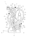
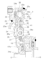
- the cross-sectional block diagram of the torque converter by one Embodiment of this invention The figure which extracts and shows the lockup apparatus of FIG.
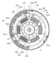
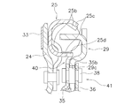
- the partial front view of a lockup apparatus The cross-sectional block diagram of a stopper mechanism.
- the front fragmentary view of a stopper mechanism The figure which shows the twist characteristic of the lockup apparatus by one Embodiment of this invention.
- FIG. 1 shows a torque converter 1 according to an embodiment of the present invention.
- An engine is arranged on the left side of FIG. 1, and a transmission is arranged on the right side of FIG. OO shown in FIG. 1 is a rotating shaft of the torque converter.
- the torque converter 1 is a device for transmitting torque from an engine-side crankshaft (not shown) to a transmission input shaft, and includes a front cover 2 fixed to an engine-side member and three types of impellers ( A torque converter main body 6 including an impeller 3, a turbine 4, and a stator 5) and a lockup device 7 are included.
- the front cover 2 is a disk-shaped member, and an outer peripheral cylindrical portion 10 that protrudes toward the transmission side is formed on the outer peripheral portion thereof.
- the impeller 3 includes an impeller shell 12 fixed to the outer peripheral cylindrical portion 10 of the front cover 2 by welding, a plurality of impeller blades 13 fixed to the inside thereof, and a cylindrical shape provided on the inner peripheral side of the impeller shell 12.
- the turbine 4 is disposed opposite to the impeller 3 in the fluid chamber.
- the turbine 4 includes a turbine shell 15, a plurality of turbine blades 16 fixed to the turbine shell 15, and a turbine hub 17 fixed to the inner peripheral side of the turbine shell 15.
- the turbine hub 17 has a flange 17 a extending to the outer peripheral side, and an inner peripheral portion of the turbine shell 15 is fixed to the flange 17 a by a plurality of rivets 18.
- An input shaft of a transmission (not shown) is splined to the inner peripheral portion of the turbine hub 17.
- the stator 5 is a mechanism for rectifying the hydraulic oil that is disposed between the impeller 3 and the inner peripheral portion of the turbine 4 and returns from the turbine 4 to the impeller 3.
- the stator 5 mainly includes a stator carrier 20 and a plurality of stator blades 21 provided on the outer peripheral surface thereof.
- the stator carrier 20 is supported by a fixed shaft (not shown) via a one-way clutch 22.
- FIG. 2 shows the lock-up device 7 extracted from FIG.
- the lockup device 7 is disposed between the front cover 2 and the turbine 4.
- the lock-up device 7 includes a piston 24, a drive plate (input plate) 25, a plurality of outer peripheral side torsion springs (outer peripheral side damper portions) 26, a driven plate (output plate) 27, and a plurality of inner peripheral side torsion springs. (Inner peripheral side damper portion) 28, an intermediate member 29, and a float member 30 are provided.
- the piston 24 is a disk-shaped plate and is disposed on the transmission side of the front cover 2.
- a cylindrical portion 24 a extending to the engine side is formed at the inner peripheral end of the piston 24.
- the cylindrical portion 24a is supported on an outer peripheral surface of a transmission-side member (not shown) so as to be axially movable and relatively rotatable.
- a flat portion 24 b is formed on the outer peripheral portion of the piston 24.
- An annular friction material 33 is fixed to the surface of the flat portion 24b on the front cover 2 side. When the friction material 33 is pressed against the front cover 2, torque is transmitted from the front cover 2 to the piston 24. That is, the piston 24 and the friction material 33 constitute a clutch portion.
- the drive plate 25 is fixed to the side surface on the transmission side in the outer peripheral portion of the piston 24. Specifically, the drive plate 25 is formed in a disk shape, and the inner peripheral portion 25 a is fixed to the transmission side surface of the piston 24 by a rivet 37.
- FIG. 3 is a view of the drive plate 25, the outer peripheral side torsion springs 26 (26a, 26b), the inner peripheral side torsion springs 28 (28a, 28b), the intermediate member 29, and the float member 30 as viewed from the transmission side.
- the members other than the above are removed.
- a plurality of engaging portions 25b are formed on the outer peripheral portion of the drive plate 25.
- the engaging portion 25b has a portion obtained by pressing the intermediate portion of the drive plate 25 toward the transmission side, and a portion obtained by bending the outer peripheral end portion toward the transmission side and the inner peripheral side.
- the engaging portion 25 b is engaged with both ends of the outer peripheral side torsion spring 26 in the circumferential direction.
- a spring support portion 25c is formed in a portion other than the portion where the engaging portion 25b is formed.
- the spring support portion 25 c is formed by bending the outer peripheral portion and the radial intermediate portion of the drive plate 25 to the transmission side, and supports the outer peripheral side and the inner peripheral side of the outer peripheral side torsion spring 26.
- a plurality of stopper claws 25d that protrude further from the tip of the spring support 25c (tip on the transmission side) to the transmission side are formed in a part of the spring support 25c that supports the inner periphery of the outer torsion spring 26. (Details will be described later).
- the outer peripheral side torsion spring 26 has a plurality of first outer peripheral side springs 26a and a plurality of second outer peripheral side springs 26b arranged side by side in the circumferential direction.
- the first outer circumferential spring 26a has a relatively long spring length
- the second outer circumferential spring 26b has a spring length that is about 1/3 of the first outer circumferential spring 26a.
- the first outer peripheral spring 26a is less rigid than the second outer peripheral spring 26b.
- the first and second outer springs 26 a and 26 b are so-called arc springs formed in an arc shape in a free state that is not incorporated in the lockup device 7. That is, FIG.
- FIG. 3 shows a state in which the outer peripheral side torsion spring 26 is supported by the spring support portion 25c of the drive plate 25, but it is also shown in FIG. 3 in a free state where it is not supported by the spring support portion 25c.
- the posture is similar to the posture.
- first outer peripheral side springs 26a and second outer peripheral side springs 26b are arranged so as to act in series. That is, one end surface in the circumferential direction of the first outer peripheral side spring 26a is in contact with the engaging portion 25b of the drive plate 25, and the other end surface is in contact with one end surface of the second outer peripheral side spring 26b. Further, the other end surface of the second outer peripheral spring 26 a is in contact with the engaging portion 25 b of the drive plate 25. That is, the first outer peripheral side spring 26a and the second outer peripheral side spring 26b are in direct contact.
- first and second outer peripheral springs 26a and 26b are arc springs, when these springs 26a and 26b are operated, the spring support portion 25c on the outer peripheral side of the drive plate 25 and both springs 26a and 26b Makes relatively strong contact. Therefore, the hysteresis torque generated between the first and second outer springs 26a and 26b and the drive plate 25 is relatively large.
- the driven plate 27 has a first plate 35 disposed on the engine side and a second plate 36 disposed on the transmission side.
- the first plate 35 and the second plate 36 are formed in a disc shape.
- first and second plates 35 and 36 are fixed to the flange 17a of the turbine hub 17 by rivets 18.
- the outer peripheral portions of both plates 35 and 36 are fixed by a stop pin 38 at a predetermined interval in the axial direction. That is, the first plate 35 and the second plate 36 are arranged to face each other with a gap in the axial direction except for the inner peripheral portion fixed to each other.
- both the plates 35 and 36 cannot rotate relative to the turbine hub 17 and cannot move in the axial direction.
- Window portions 35a and 36a are formed in the intermediate portion in the radial direction of the first plate 35 and the second plate 36.
- the outer peripheral edge and the inner peripheral edge of the window portions 35a and 36a are cut and raised outward in the axial direction.
- the movement of the inner peripheral side torsion spring 28 in the axial direction and the radial direction is restricted by the window portions 35a and 36a.
- the shape of the outer peripheral side of the window portions 35a and 36a is an arc shape in which the outer periphery of the set inner peripheral torsion spring 28 swells to the outer peripheral side than the circular arc drawn during operation. Therefore, when the inner peripheral side torsion spring 28 is operated, the window portions 35a and 36a and the outer periphery of the inner peripheral side torsion spring 28 are difficult to slide. For this reason, the hysteresis torque generated between the inner peripheral side torsion spring 28 and the plates 35 and 36 is small.
- the intermediate member 29 is disposed between the drive plate 25 and the turbine 4 in the axial direction, and is rotatable relative to the drive plate 25 and the driven plate 27. As illustrated in FIG. 3, the intermediate member 29 is an annular member, and includes a plurality of outer peripheral side engaging portions 29 a and a plurality of inner peripheral side engaging portions 29 b.
- the outer peripheral side engaging portion 29 a is provided at a predetermined interval in the circumferential direction at the outer peripheral end portion of the intermediate member 29.
- the outer peripheral side engaging portion 29a is formed by bending the outer peripheral end portion of the intermediate member 29 toward the engine side.
- the outer peripheral side engaging portion 29a is disposed between two adjacent sets of outer peripheral side torsion springs 26. One end surface of one set of first outer peripheral side springs 26a and the other set of second outer peripheral side springs 26b. Is engaged with the other end surface.
- the inner peripheral side engaging portions 29b are provided at predetermined intervals in the circumferential direction at the inner peripheral end portion of the intermediate member 29.
- the inner peripheral side engaging portion 29b is formed by further protruding the inner peripheral end portion of the intermediate member 29 toward the inner peripheral side, and is provided between the two outer peripheral side engaging portions 29a in the circumferential direction. Further, the inner peripheral engagement portion 29 b is disposed between the first plate 35 and the second plate 36 of the driven plate 27 in the axial direction.
- the float member 30 is disposed between the first plate 35 and the second plate 36 in the axial direction on the inner peripheral side of the intermediate member 29.
- the float member 30 is rotatable relative to the drive plate 25, the intermediate member 29, and the driven plate 27.
- the float member 30 is an annular plate and includes a plurality of engaging portions 30 a that are formed to protrude from the outer peripheral end portion toward the outer peripheral side.
- the engaging portion 30 a is disposed between the circumferential directions of the inner peripheral side engaging portions 29 b adjacent to the intermediate member 29.
- the engaging portion 30a is disposed between the adjacent inner torsion springs 28 adjacent to each other.
- the inner circumferential side torsion spring 28 includes a first inner circumferential side spring 28a and a second inner circumferential side spring 28b disposed inside the first inner circumferential side spring 28a.
- the second inner peripheral spring 28b has a shorter spring length than the first inner peripheral spring 28a.
- the outer peripheral shape of the window portions 35a and 36a of the first and second plates 35 and 36 is an arc in which the outer periphery of the first inner spring 28a swells more outward than the arc drawn during operation. Shape. Further, the first and second inner peripheral springs 28 a and 28 b are formed in a straight line in a free state that is not incorporated in the lockup device 7. With such a configuration, the hysteresis torque generated between the first inner peripheral spring 28a and the two plates 35 and 36 can be further reduced.
- the lockup device 7 includes first and second stopper mechanisms 40 and 41.
- the first stopper mechanism 40 regulates the relative rotation angle between the drive plate 25 and the driven plate 27.
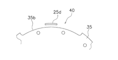
- the first stopper mechanism 40 includes a stopper claw 25 d provided in a part of the drive plate 25 and a notch 35 b formed at the outer peripheral end of the first plate 35 of the driven plate 27. And is composed of.
- the second stopper mechanism 41 regulates the relative rotation angle between the intermediate member 29 and the driven plate 27.
- the second stopper mechanism 41 includes a circumferentially long notch 29 c formed in the intermediate member 29, and a stop pin 38 that connects both the plates 35 and 36 of the driven plate 27. , Is composed of.
- the stopper claw 25d is formed by extending a part of the spring support portion 25c of the drive plate 25 to the transmission side. Specifically, the spring support portion 25c does not overlap the first plate 35 in the axial direction, but the stopper claw 25d extends to a position where it overlaps the first plate 35 in the axial direction.
- FIG. 5 shows a front view of the stopper mechanism 40.
- the notch 35 b is formed in the outer peripheral edge portion of the first plate 35 so as to open to the outer peripheral side.
- the notch 35b is formed over a predetermined angular range, and a stopper claw 25d is inserted into the notch 35b.
- the drive plate 25 can rotate relative to the driven plate 27 until the stopper claw 25d abuts on the circumferential end of the notch 35b. In other words, the rotation of the drive plate 25 relative to the driven plate 27 is prohibited by the stopper claw 25d coming into contact with the end surface of the notch 35b.
- the pair of first outer peripheral side springs 26a and second outer peripheral side springs 26b act in series.
- one set (two) of inner peripheral side torsion springs 28 also act in series by the float member 30.
- the outer peripheral side torsion spring 26 and the inner peripheral side torsion spring 28 act in series by the intermediate member 29. For this reason, the torsion characteristic can be made low in rigidity and the torsion angle can be widened.
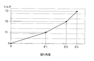
- Fig. 6 shows the torsional characteristics.
- the relative rotation angle between the drive plate 25 and the driven plate 27, that is, the twist angle is 0 to ⁇ 1.
- the first outer peripheral side spring 26a, the second outer peripheral side spring 26b, and the first inner peripheral side spring 28a are compressed, and the torsional characteristics with the lowest rigidity are obtained.
- the first inner circumferential spring 28a When the input torque is further increased and the twist angle becomes ⁇ 2, the first inner circumferential spring 28a is compressed until it has the same length as the second inner circumferential spring 28b. Therefore, when the input torque exceeds T2 and the torsion angle reaches the third stage of ⁇ 2 or more, the second inner peripheral spring 28b operates in addition to the second outer peripheral spring 26b and the first inner peripheral spring 28a. As a result, in the region where the twist angle is ⁇ 2 or more, the torsional characteristics with the highest rigidity are obtained.
- the first stopper mechanism 40 operates. That is, the stopper claw 25d of the drive plate 25 abuts on the end surface of the notch 35b of the driven plate 27, and relative rotation between the drive plate 25 and the driven plate 27 is prohibited.
- the second stopper mechanism 41 also operates simultaneously with the first stopper mechanism 40. That is, the stopper pin 38 contacts the end surface of the notch 29c of the intermediate member 29, and relative rotation between the intermediate member 29 and the driven plate 27 is prohibited.
- the first and second outer springs 26a and 26b are set to be compressed. In this case, the torsion characteristic with the lowest rigidity is obtained.
- the second inner peripheral spring 28b is set to be compressed. In this case, a torsional characteristic with medium rigidity is obtained.
- the first outer spring 28a is brought into close contact, and the remaining springs 26b, 28a, 28b are operated. In this case, a high rigidity torsion characteristic is obtained.
- the hysteresis torque generated between the outer peripheral side torsion spring 26 and the drive plate 25 can be increased, and the hysteresis torque generated between the inner peripheral side torsion spring 28 and the first and second plates 35 and 36 can be decreased. it can. Further, the outer periphery side torsion spring 26 can have high rigidity, and the inner periphery side torsion spring 28 can have low rigidity.
- the damper portion on the outer peripheral side can have a torsional characteristic of high rigidity and high hysteresis torque, and can effectively absorb sound and vibration when excessive torque is suddenly input.
- the damper portion on the inner peripheral side can have a torsional characteristic of low rigidity and low hysteresis torque, which is advantageous for a low-pitched sound.
- the friction member is provided on the front cover side surface of the piston.
- a clutch portion including a plurality of friction members is provided, and torque is transmitted from the front cover to the torsion spring via the clutch portion.
- the present invention can be similarly applied to an apparatus.
- the lock-up device can achieve low rigidity and wide angle of torsional characteristics with a simple configuration.
Landscapes
- Engineering & Computer Science (AREA)
- General Engineering & Computer Science (AREA)
- Mechanical Engineering (AREA)
- Physics & Mathematics (AREA)
- Acoustics & Sound (AREA)
- Aviation & Aerospace Engineering (AREA)
- Mechanical Operated Clutches (AREA)
Priority Applications (2)
| Application Number | Priority Date | Filing Date | Title |
|---|---|---|---|
| CN201680009241.XA CN107208768B (zh) | 2015-02-23 | 2016-01-18 | 液力变矩器的锁定装置 |
| US15/552,173 US10337596B2 (en) | 2015-02-23 | 2016-01-18 | Lock-up device for torque converter |
Applications Claiming Priority (2)
| Application Number | Priority Date | Filing Date | Title |
|---|---|---|---|
| JP2015032467A JP2016156384A (ja) | 2015-02-23 | 2015-02-23 | トルクコンバータのロックアップ装置 |
| JP2015-032467 | 2015-02-23 |
Publications (1)
| Publication Number | Publication Date |
|---|---|
| WO2016136325A1 true WO2016136325A1 (ja) | 2016-09-01 |
Family
ID=56789255
Family Applications (1)
| Application Number | Title | Priority Date | Filing Date |
|---|---|---|---|
| PCT/JP2016/051218 Ceased WO2016136325A1 (ja) | 2015-02-23 | 2016-01-18 | トルクコンバータのロックアップ装置 |
Country Status (4)
| Country | Link |
|---|---|
| US (1) | US10337596B2 (enExample) |
| JP (1) | JP2016156384A (enExample) |
| CN (1) | CN107208768B (enExample) |
| WO (1) | WO2016136325A1 (enExample) |
Families Citing this family (1)
| Publication number | Priority date | Publication date | Assignee | Title |
|---|---|---|---|---|
| JP7451307B2 (ja) | 2020-06-01 | 2024-03-18 | 株式会社エクセディ | ロックアップ装置 |
Citations (4)
| Publication number | Priority date | Publication date | Assignee | Title |
|---|---|---|---|---|
| JP2004156692A (ja) * | 2002-11-06 | 2004-06-03 | Exedy Corp | 流体式トルク伝達装置のロックアップ装置 |
| JP2008256017A (ja) * | 2007-04-02 | 2008-10-23 | F C C:Kk | ロックアップクラッチ |
| JP2011179557A (ja) * | 2010-02-26 | 2011-09-15 | Aisin Aw Industries Co Ltd | ダンパ装置 |
| JP2012122584A (ja) * | 2010-12-10 | 2012-06-28 | Exedy Corp | 流体継手用ロックアップ装置 |
Family Cites Families (14)
| Publication number | Priority date | Publication date | Assignee | Title |
|---|---|---|---|---|
| SE443618B (sv) * | 1979-12-26 | 1986-03-03 | Borg Warner | Tvastegs torsionssvengningsdempare |
| JP3828226B2 (ja) * | 1997-02-05 | 2006-10-04 | Nskワーナー株式会社 | ロックアップクラッチのダンパー装置 |
| CN101305214A (zh) | 2005-11-10 | 2008-11-12 | 卢克摩擦片和离合器两合公司 | 扭转振动减振器以及用于机动车动力总成系统的液力变矩器装置 |
| EP1948972A2 (de) * | 2005-11-10 | 2008-07-30 | LuK Lamellen und Kupplungsbau Beteiligungs KG | Hydrodynamische drehmomentwandler-vorrichtung für einen kraftfahrzeug- antriebsstrang |
| CN201106670Y (zh) | 2007-08-17 | 2008-08-27 | 奇瑞汽车股份有限公司 | 一种液力变矩器 |
| JP5081611B2 (ja) * | 2007-12-25 | 2012-11-28 | アイシン・エィ・ダブリュ工業株式会社 | トルクコンバータのロックアップダンパ装置 |
| JP2009250288A (ja) | 2008-04-02 | 2009-10-29 | Exedy Corp | ロックアップ装置 |
| JP5164731B2 (ja) | 2008-08-08 | 2013-03-21 | 日本発條株式会社 | ダンパスプリング装置、フライホイール、クラッチディスク、ロックアップ機構用クラッチディスク |
| JP4755277B2 (ja) | 2009-12-10 | 2011-08-24 | 株式会社エクセディ | トルクコンバータ用ロックアップ装置 |
| US9011257B2 (en) | 2010-11-11 | 2015-04-21 | Exedy Corporation | Lock-up device for fluid coupling |
| JP5418519B2 (ja) * | 2011-02-15 | 2014-02-19 | アイシン・エィ・ダブリュ株式会社 | ダンパ装置 |
| JP5418531B2 (ja) * | 2011-03-28 | 2014-02-19 | アイシン・エィ・ダブリュ株式会社 | ダンパ装置 |
| US20130022530A1 (en) * | 2011-07-19 | 2013-01-24 | Robert Angelo Mercuri | Production Of Exfoliated Graphite |
| CN203703044U (zh) | 2014-01-24 | 2014-07-09 | 法雷奥汽车自动传动系统(南京)有限公司 | 一种液力变矩器用大扭转角减振器 |
-
2015
- 2015-02-23 JP JP2015032467A patent/JP2016156384A/ja active Pending
-
2016
- 2016-01-18 CN CN201680009241.XA patent/CN107208768B/zh active Active
- 2016-01-18 WO PCT/JP2016/051218 patent/WO2016136325A1/ja not_active Ceased
- 2016-01-18 US US15/552,173 patent/US10337596B2/en active Active
Patent Citations (4)
| Publication number | Priority date | Publication date | Assignee | Title |
|---|---|---|---|---|
| JP2004156692A (ja) * | 2002-11-06 | 2004-06-03 | Exedy Corp | 流体式トルク伝達装置のロックアップ装置 |
| JP2008256017A (ja) * | 2007-04-02 | 2008-10-23 | F C C:Kk | ロックアップクラッチ |
| JP2011179557A (ja) * | 2010-02-26 | 2011-09-15 | Aisin Aw Industries Co Ltd | ダンパ装置 |
| JP2012122584A (ja) * | 2010-12-10 | 2012-06-28 | Exedy Corp | 流体継手用ロックアップ装置 |
Also Published As
| Publication number | Publication date |
|---|---|
| CN107208768B (zh) | 2020-06-16 |
| CN107208768A (zh) | 2017-09-26 |
| US10337596B2 (en) | 2019-07-02 |
| JP2016156384A (ja) | 2016-09-01 |
| US20180038465A1 (en) | 2018-02-08 |
Similar Documents
| Publication | Publication Date | Title |
|---|---|---|
| JP5852701B2 (ja) | 流体式動力伝達装置 | |
| JP5828030B1 (ja) | トルクコンバータのロックアップ装置 | |
| US9989136B2 (en) | Starting device | |
| JP5832472B2 (ja) | トルクダンパ装置 | |
| JP2011122622A (ja) | トルクコンバータ用ロックアップ装置 | |
| JP2004270786A (ja) | ダンパ装置およびロックアップクラッチ装置 | |
| JP2001082577A (ja) | トルクコンバータ用ロックアップ装置 | |
| JP2009185847A (ja) | 捩り振動低減装置 | |
| KR20160008541A (ko) | 토크 컨버터의 록업 장치 | |
| JP6605280B2 (ja) | ダンパ装置 | |
| JP6197738B2 (ja) | 発進装置 | |
| JP2011099488A (ja) | トルクコンバータの動力伝達装置 | |
| US20160017972A1 (en) | Lock-up device for torque converter | |
| JP6325926B2 (ja) | トルクコンバータのロックアップ装置 | |
| WO2016136325A1 (ja) | トルクコンバータのロックアップ装置 | |
| JP5951082B2 (ja) | トルクコンバータのロックアップ装置 | |
| JP6562872B2 (ja) | ダンパ装置 | |
| JP2006162054A5 (enExample) | ||
| CN107110325B (zh) | 液力变矩器用的锁定装置 | |
| JP2006162054A (ja) | ダンパーディスク組立体 | |
| JP5951081B2 (ja) | トルクコンバータのロックアップ装置 | |
| JP6287763B2 (ja) | 発進装置 | |
| JP6234182B2 (ja) | トルクコンバータのロックアップ装置 |
Legal Events
| Date | Code | Title | Description |
|---|---|---|---|
| 121 | Ep: the epo has been informed by wipo that ep was designated in this application |
Ref document number: 16755075 Country of ref document: EP Kind code of ref document: A1 |
|
| WWE | Wipo information: entry into national phase |
Ref document number: 15552173 Country of ref document: US |
|
| NENP | Non-entry into the national phase |
Ref country code: DE |
|
| 122 | Ep: pct application non-entry in european phase |
Ref document number: 16755075 Country of ref document: EP Kind code of ref document: A1 |