WO2016136239A1 - 弁装置 - Google Patents
弁装置 Download PDFInfo
- Publication number
- WO2016136239A1 WO2016136239A1 PCT/JP2016/000955 JP2016000955W WO2016136239A1 WO 2016136239 A1 WO2016136239 A1 WO 2016136239A1 JP 2016000955 W JP2016000955 W JP 2016000955W WO 2016136239 A1 WO2016136239 A1 WO 2016136239A1
- Authority
- WO
- WIPO (PCT)
- Prior art keywords
- valve body
- passage
- pilot
- pressure chamber
- main valve
- Prior art date
- Legal status (The legal status is an assumption and is not a legal conclusion. Google has not performed a legal analysis and makes no representation as to the accuracy of the status listed.)
- Ceased
Links
Images




Classifications
-
- F—MECHANICAL ENGINEERING; LIGHTING; HEATING; WEAPONS; BLASTING
- F02—COMBUSTION ENGINES; HOT-GAS OR COMBUSTION-PRODUCT ENGINE PLANTS
- F02M—SUPPLYING COMBUSTION ENGINES IN GENERAL WITH COMBUSTIBLE MIXTURES OR CONSTITUENTS THEREOF
- F02M21/00—Apparatus for supplying engines with non-liquid fuels, e.g. gaseous fuels stored in liquid form
- F02M21/02—Apparatus for supplying engines with non-liquid fuels, e.g. gaseous fuels stored in liquid form for gaseous fuels
- F02M21/0218—Details on the gaseous fuel supply system, e.g. tanks, valves, pipes, pumps, rails, injectors or mixers
- F02M21/023—Valves; Pressure or flow regulators in the fuel supply or return system
- F02M21/0233—Details of actuators therefor
-
- F—MECHANICAL ENGINEERING; LIGHTING; HEATING; WEAPONS; BLASTING
- F16—ENGINEERING ELEMENTS AND UNITS; GENERAL MEASURES FOR PRODUCING AND MAINTAINING EFFECTIVE FUNCTIONING OF MACHINES OR INSTALLATIONS; THERMAL INSULATION IN GENERAL
- F16K—VALVES; TAPS; COCKS; ACTUATING-FLOATS; DEVICES FOR VENTING OR AERATING
- F16K31/00—Actuating devices; Operating means; Releasing devices
- F16K31/02—Actuating devices; Operating means; Releasing devices electric; magnetic
- F16K31/06—Actuating devices; Operating means; Releasing devices electric; magnetic using a magnet, e.g. diaphragm valves, cutting off by means of a liquid
- F16K31/0644—One-way valve
- F16K31/0655—Lift valves
-
- F—MECHANICAL ENGINEERING; LIGHTING; HEATING; WEAPONS; BLASTING
- F16—ENGINEERING ELEMENTS AND UNITS; GENERAL MEASURES FOR PRODUCING AND MAINTAINING EFFECTIVE FUNCTIONING OF MACHINES OR INSTALLATIONS; THERMAL INSULATION IN GENERAL
- F16K—VALVES; TAPS; COCKS; ACTUATING-FLOATS; DEVICES FOR VENTING OR AERATING
- F16K31/00—Actuating devices; Operating means; Releasing devices
- F16K31/12—Actuating devices; Operating means; Releasing devices actuated by fluid
- F16K31/42—Actuating devices; Operating means; Releasing devices actuated by fluid by means of electrically-actuated members in the supply or discharge conduits of the fluid motor
-
- F—MECHANICAL ENGINEERING; LIGHTING; HEATING; WEAPONS; BLASTING
- F17—STORING OR DISTRIBUTING GASES OR LIQUIDS
- F17C—VESSELS FOR CONTAINING OR STORING COMPRESSED, LIQUEFIED OR SOLIDIFIED GASES; FIXED-CAPACITY GAS-HOLDERS; FILLING VESSELS WITH, OR DISCHARGING FROM VESSELS, COMPRESSED, LIQUEFIED, OR SOLIDIFIED GASES
- F17C13/00—Details of vessels or of the filling or discharging of vessels
-
- F—MECHANICAL ENGINEERING; LIGHTING; HEATING; WEAPONS; BLASTING
- F17—STORING OR DISTRIBUTING GASES OR LIQUIDS
- F17C—VESSELS FOR CONTAINING OR STORING COMPRESSED, LIQUEFIED OR SOLIDIFIED GASES; FIXED-CAPACITY GAS-HOLDERS; FILLING VESSELS WITH, OR DISCHARGING FROM VESSELS, COMPRESSED, LIQUEFIED, OR SOLIDIFIED GASES
- F17C2205/00—Vessel construction, in particular mounting arrangements, attachments or identifications means
- F17C2205/03—Fluid connections, filters, valves, closure means or other attachments
- F17C2205/0302—Fittings, valves, filters, or components in connection with the gas storage device
- F17C2205/0323—Valves
- F17C2205/0326—Valves electrically actuated
-
- F—MECHANICAL ENGINEERING; LIGHTING; HEATING; WEAPONS; BLASTING
- F17—STORING OR DISTRIBUTING GASES OR LIQUIDS
- F17C—VESSELS FOR CONTAINING OR STORING COMPRESSED, LIQUEFIED OR SOLIDIFIED GASES; FIXED-CAPACITY GAS-HOLDERS; FILLING VESSELS WITH, OR DISCHARGING FROM VESSELS, COMPRESSED, LIQUEFIED, OR SOLIDIFIED GASES
- F17C2205/00—Vessel construction, in particular mounting arrangements, attachments or identifications means
- F17C2205/03—Fluid connections, filters, valves, closure means or other attachments
- F17C2205/0302—Fittings, valves, filters, or components in connection with the gas storage device
- F17C2205/0382—Constructional details of valves, regulators
- F17C2205/0385—Constructional details of valves, regulators in blocks or units
-
- Y—GENERAL TAGGING OF NEW TECHNOLOGICAL DEVELOPMENTS; GENERAL TAGGING OF CROSS-SECTIONAL TECHNOLOGIES SPANNING OVER SEVERAL SECTIONS OF THE IPC; TECHNICAL SUBJECTS COVERED BY FORMER USPC CROSS-REFERENCE ART COLLECTIONS [XRACs] AND DIGESTS
- Y02—TECHNOLOGIES OR APPLICATIONS FOR MITIGATION OR ADAPTATION AGAINST CLIMATE CHANGE
- Y02T—CLIMATE CHANGE MITIGATION TECHNOLOGIES RELATED TO TRANSPORTATION
- Y02T10/00—Road transport of goods or passengers
- Y02T10/10—Internal combustion engine [ICE] based vehicles
- Y02T10/30—Use of alternative fuels, e.g. biofuels
Definitions
- the present invention relates to a valve device used as, for example, a pneumatic control device or a gas tank plug.
- Patent Document 1 discloses a valve device in which a main valve body and a pilot valve body are arranged coaxially.
- FIG. 10 shows a part of the valve device 100 disclosed in Patent Document 1.
- a primary passage 121, a pressure chamber 122, and a secondary passage 123 constituting the main passage 120 are formed in the housing 110, and the secondary passage 123 is opened and closed by the main valve body 140.
- a pilot chamber 130 is formed on the opposite side of the main valve body 140 from the pressure chamber 122, and the pilot chamber 130 is pressurized through a first pilot passage 131 that is a gap between the main valve body 140 and the housing 110. It communicates with the chamber 122.
- a second pilot passage 132 is formed in the main valve body 140, and the second pilot passage 132 is opened and closed by the pilot valve body 150.
- the pilot valve body 150 is driven by a solenoid (not shown).
- the main valve body 140 and the pilot valve body 150 are connected by a pin 160.
- the pin 160 is fitted into the lateral hole provided in the pilot valve body 150 without a gap, a gap is formed between the pin 160 and the support hole 141 provided in the main valve body 140.
- the valve body 150 can be separated from the main valve body 140 by the gap.
- the pilot valve body 150 is pressed against the main valve body 140 by a spring (not shown).
- the solenoid (not shown) is energized, first, the pilot valve body 150 is separated from the main valve body 140 by the gap between the support hole 141 and the pin 160. Thereby, the second pilot passage 132 is opened. Thereafter, when the differential pressure between the pilot chamber 130 and the secondary passage 123 is reduced, and the suction force of the pilot valve body 150 by the solenoid overcomes the biasing force of the spring that biases the pilot valve body 150 and the pressure of the pilot chamber 130, The main valve body 140 is pulled up. As a result, the secondary passage 123 is opened.
- an object of the present invention is to provide a valve device that can reduce the size of a drive mechanism for a pilot valve body and is excellent in responsiveness.
- a valve device of the present invention includes a housing having a valve body space between the primary passage and the secondary passage, in which a primary passage and a secondary passage constituting a main passage are formed.
- a main valve body for opening and closing the secondary passage which is disposed in the housing so as to partition the valve body space into a first pressure chamber and a second pressure chamber communicating with the primary passage and the secondary passage;
- a seal member that is disposed in an annular groove provided in the main valve body and is covered with the housing, and that separates the first pressure chamber and the second pressure chamber, and one end of the primary passage
- a first pilot passage having a first restriction, the other end communicating with the second pressure chamber, and the main valve extending from the second pressure chamber to the secondary passage.
- a second pilot having a second aperture formed in the body A pilot valve body that opens and closes the second pilot passage, a biasing member that presses the pilot valve body against the main valve body, and the pilot valve body that is energized to A driving mechanism that drives the biasing member in a direction to open the second pilot passage, and a pin that connects the main valve body and the pilot valve body, the main valve body or the pilot A pin formed with a gap that allows the pilot valve body to be separated from the main valve body, and the main valve body opens the second pilot passage by the pilot valve body.
- the sealing member includes the housing and the slide to spiral rings, characterized in that.
- the valve device since the main valve body is driven in the opening direction by the differential pressure between the first pressure chamber and the second pressure chamber, if the second pilot passage is opened by the pilot valve body, The main valve element opens instantly due to the pressure drop. Therefore, the valve device has excellent responsiveness.
- the drive mechanism for the pilot valve body only needs to have the power necessary to drive the pilot valve body by the gap between the pin and the main valve body or the pilot valve body. be able to.
- the second pilot passage having the second throttle is formed in the main valve body, the valve seat area of the pilot valve body is reduced, and the pilot valve body can be opened with less driving power. . Further, since the main valve body and the pilot valve body are connected by the pin, the state where the main valve body opens the secondary passage can be maintained by using the power of the drive mechanism.
- the seal member attached to the main valve body is a flat ring that slides with the housing and has a bias cut type flat ring in which an oblique cut is formed so that it can be enlarged at the time of attachment, and the flat ring has a diameter. It is also possible to use one that includes an elastic body that urges outward in the direction. However, in this case, in order to stably generate the differential pressure between the first pressure chamber and the second pressure chamber, it is necessary to strictly manage the cut size of the flat ring after mounting. On the other hand, if a sealing member including a spiral ring is used as in the present invention, the distance between the surrounding portions of the spiral ring is relatively long, so that the gap between these surrounding portions is not strictly managed. However, sufficient sealing performance can be ensured. Therefore, it is not necessary to manage the dimensions after mounting such as a flat ring, and the manufacturing cost can be reduced.
- the spiral ring is formed by winding a single wire so that at least both ends of the wire overlap the surrounding portion, and a wedge-shaped gap is formed between the both ends of the wire and the surrounding portion. It may be tapered as is done. According to this configuration, when the spiral ring is fitted into the annular groove of the main valve body, the circumferential portion can be smoothly deformed along the shape of both end portions between the both ends of the wire rod, and the spiral ring can be easily Can be flat.
- the seal member may include an elastic body that biases the spiral ring outward in the radial direction.
- the spiral ring is a flat ring that slides with the housing, and both overlapping ends of the wire extending in the circumferential direction of the flat ring are in surface contact with each other on a plane perpendicular to the axial direction of the flat ring.
- a flat ring having a stepped shape may be used.
- the seal member may include an elastic body that biases the flat ring radially outward.
- the drive mechanism is a solenoid including a fixed magnetic pole that attracts the pilot valve body, and the housing is provided with a stopper for the main valve body, and the second pilot passage and the secondary passage are closed.
- the distance from the pilot valve body to the fixed magnetic pole may be greater than the distance from the main valve body to the stopper and the sum of the gaps. According to this configuration, the main valve body can be pressed against the stopper by the suction force of the solenoid while the solenoid is energized.
- the first pilot passage may be formed in the housing or the main valve body. According to this configuration, the first aperture can be formed with high accuracy by machining.
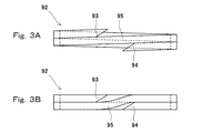
- FIG. 3A is a side view of the spiral ring before being fitted into the annular groove of the main valve body
- FIG. 3B is a side view of the spiral ring after being fitted into the annular groove of the main valve body. It is a side view of a bias cut type flat ring. It is a schematic block diagram of the valve apparatus which concerns on 2nd Embodiment of this invention.
- FIG. 6 is a side view of a flat ring that can be used instead of a spiral ring. It is a sectional view of a part of a conventional valve device.
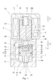
- (First embodiment) 1 and 2 show a valve device 1A according to a first embodiment of the present invention.
- the valve device 1A is used as a pneumatic control device, a gas tank plug, or the like.
- the fluid targeted by the valve device 1A is, for example, high-pressure gas.
- the valve device 1A of the present embodiment is a solenoid valve.
- the valve device 1 ⁇ / b> A includes a housing 2, a main valve body 4 and a pilot valve body 5 disposed in the housing 2, and a solenoid (drive mechanism) 7 that drives the pilot valve body 5.
- a solenoid (drive mechanism) 7 that drives the pilot valve body 5.
- the valve device 1A is not limited to a solenoid valve that employs the solenoid 7 as a drive mechanism.
- a piezoelectric actuator may be used as the drive mechanism.
- the piezoelectric actuator includes a piezoelectric element (for example, a piezo element) and generates a driving force according to an applied voltage.
- a force motor may be used as the drive mechanism. In the force motor, a movable coil is inserted into a cylindrical permanent magnet, and when a current is passed through the movable coil, an exciting force corresponding to the current is generated, and the movable coil is moved by this exciting force. .
- the main valve body 4 and the pilot valve body 5 are both rod-shaped members having a circular cross section, and their central axes are located on the same straight line. In other words, the main valve body 4 and the pilot valve body 5 are arranged coaxially.
- the direction in which the main valve body 4 and the pilot valve body 5 are aligned is the vertical direction (the pilot valve body 5 side is upward, the main valve body is The 4th side is called the lower side.
- the direction in which the main valve body 4 and the pilot valve body 5 are arranged may be a horizontal direction or an oblique direction.
- the housing 2 includes a first body 21 in which a primary passage 31 and a secondary passage 33 constituting the main passage 3 are formed, and a second body 22 in which a solenoid 7 is incorporated.
- the housing 2 has a valve body space 20 between the primary passage 31 and the secondary passage 33.
- the valve body space 20 extends across the first main body 21 and the second main body 22.
- the first main body 21 is formed with a cylindrical first sliding chamber 20a that holds the main valve body 4 so as to be slidable in the vertical direction, and the second main body 22 has a pilot valve body.
- a cylindrical second sliding chamber 20b is formed to hold 5 in a slidable manner in the vertical direction.
- the first main body 21 is provided with a stopper 23 that protrudes radially inward between the first sliding chamber 20a and the second sliding chamber 20b and stops the main valve body 4 that moves upward.
- the valve body space 20 described above is a continuous space defined by the first sliding chamber 20a, the stopper 23, and the second sliding chamber 20b.
- One end (upstream end) of the primary passage 31 is open to the side surface of the first main body 21, and the other end (downstream end) is open to the peripheral surface of the first sliding chamber 20a.
- one end (upstream end) of the secondary passage 33 opens on the bottom surface of the first sliding chamber 20 a, and the other end (downstream end) opens on the lower surface of the first main body 21.
- a first valve seat 25 for the main valve body 4 is formed around the upstream end of the secondary passage 33 on the bottom surface of the first sliding chamber 20a.
- the main valve body 4 is arranged in the housing 2 so as to partition the valve body space 20 into a first pressure chamber 32 and a second pressure chamber 24 communicating with the primary passage 31 and the secondary passage 33.
- the first pressure chamber 32 constitutes the main passage 3 together with the primary passage 31 and the secondary passage 33.
- the main valve body 4 includes a shaft portion 41 having a diameter smaller than the diameter of the peripheral surface of the first sliding chamber 20a and a first sliding chamber 20a extending upward from a peripheral portion on the upper side of the shaft portion 41. And a cylindrical portion 42 having an outer diameter substantially equal to the diameter of the peripheral surface.
- the cylindrical portion 42 is a portion that is slidably held in the first sliding chamber 20a. That is, the first pressure chamber 32 is defined between a portion of the peripheral surface of the first sliding chamber 20 a that is lower than the cylindrical portion 42 and the outer peripheral surface of the shaft portion 41.
- the second pressure chamber 24 is a space facing the upper surface of the shaft portion 41 and the inner peripheral surface of the cylindrical portion 42, a region above the main valve body 4 in the first sliding chamber 20 a, and the stopper 23. It is comprised by the inside and the 2nd sliding chamber 20b.
- a seal member 9 that separates the first pressure chamber 32 and the second pressure chamber 24 is attached to the cylindrical portion 42 of the main valve body 4.
- the outer circumferential surface of the cylindrical portion 42 is provided with an annular groove that opens outward in the radial direction and is covered by the circumferential surface of the first sliding chamber 20a.
- the seal member 9 is disposed in the annular groove. The seal member 9 will be described in detail later.
- the main valve body 4 moves between a closed position where the shaft portion 41 is seated on the first valve seat 25 and an open position where the tubular portion 42 abuts against the stopper 23 to open and close the secondary passage 33.
- the secondary passage 33 is closed and the first pressure chamber 32 is isolated from the secondary passage 33, and when the shaft portion 41 is separated from the first valve seat 25, the secondary passage 33 is closed.
- the passage 33 is opened and the first pressure chamber 32 is connected to the secondary passage 33.
- a first pilot passage 61 is formed in the first main body 21 of the housing 2. One end (upstream end) of the first pilot passage 61 communicates directly with the primary passage 31, and the other end (downstream end) of the first pilot passage 61 communicates with the second pressure chamber 24.
- the first pilot passage 61 is provided with a first throttle 62 in the middle.
- a second pilot passage 63 is formed in the main valve body 4 so as to reach from the second pressure chamber 24 to the secondary passage 33.
- the second pilot passage 63 is disposed on the central axis of the main valve body 4, and one end (upstream end) of the second pilot passage 63 opens on the upper surface of the shaft portion 41, and the other end (downstream end) is the shaft portion. 41 is open to the tip surface.
- the second pilot passage 63 is provided with a second throttle 64 at the end on the second pressure chamber 24 side. The second pilot passage 63 is opened and closed by the pilot valve body 5.
- the pilot valve body 5 is disposed in the second pressure chamber 24.
- a biasing member 55 that presses the pilot valve body 5 against the main valve body 4 is disposed in the second pressure chamber 24.
- the urging member 55 is, for example, a compression coil spring.
- a vertical hole 53 on the central axis and a horizontal hole 54 that intersects with the lower end of the vertical hole 53 are formed in order to avoid the second pressure chamber 24 being vertically divided by the pilot valve body 5.
- a horizontal hole 54 that intersects with the lower end of the vertical hole 53 are formed in order to avoid the second pressure chamber 24 being vertically divided by the pilot valve body 5.
- pilot valve body 5 is inserted into the main body 51 that is slidably held in the second sliding chamber 20 b and the cylindrical portion 42 of the main valve body 4 that protrudes downward from the main body 51. And a shaft portion 52.
- a second valve seat 45 for the pilot valve body 5 is formed around the upstream end of the second pilot passage 63 on the upper surface of the shaft portion 41 of the main valve body 4.
- the second pilot passage 63 is closed, the second pressure chamber 24 is isolated from the second pilot passage 63, and when the shaft portion 52 is separated from the second valve seat 45, The second pilot passage 63 is opened and the second pressure chamber 24 is connected to the second pilot passage 63.
- the inner peripheral surface of the tubular portion 42 of the main valve body 4 and the shaft portion 52 of the pilot valve body 5. Through the gap between the outer peripheral surface of the main valve body 4 and the top surface of the shaft portion 41 of the main valve body 4 and the tip surface of the shaft portion 52 of the pilot valve body 5. Led.
- the solenoid 7 described above drives the pilot valve body 5 in a direction to open the second pilot passage 63 against the urging force of the urging member 55 by energization. That is, the pilot valve body 5 also functions as a movable iron core that is driven by the solenoid 7.
- the solenoid 7 includes a coil 71 wound around the second sliding chamber 20 b and a fixed magnetic pole 72 that is disposed above the pilot valve body 5 and attracts the pilot valve body 5.
- the fixed magnetic pole 72 is also a part of the second main body 22 of the housing 2.
- the shaft portion 52 of the pilot valve body 5 and the cylindrical portion 42 of the main valve body 4 are connected by a pin 8 extending in the horizontal direction perpendicular to the vertical direction.
- the shaft portion 52 of the pilot valve body 5 is formed with a lateral hole 56 that is inserted into the pin 8
- the cylindrical portion 42 of the main valve body 4 is formed with a support hole 43 that supports both ends of the pin 8.
- the support hole 43 is fitted to the pin 8 without a gap, and a gap is provided between the pin 8 and the lateral hole 56 below the pin 8 in a state where the pilot valve body 5 is in contact with the main valve body 4. e1 is formed.
- the horizontal hole 56 may be a circular hole having a diameter larger than that of the pin 8 or may be a long hole extending in the vertical direction with the same width as the diameter of the pin 8.
- the solenoid 7 sets the secondary pressure as the pressure of the secondary passage 33 to P2, the area of the second valve seat 45 to Ap, and the biasing force of the biasing member 55 to Fs.
- the suction force Fc is larger than Fs + Ap (P1-P2).
- the main valve body 4 When the second pilot passage 63 is opened by the pilot valve body 5 and the pressure in the second pressure chamber 24 is lower than the pressure in the first pressure chamber 32, the main valve body 4 has the second pressure passage 32 and the second pressure chamber 32. It is configured to be driven in a direction to open the secondary passage 33 by the differential pressure in the pressure chamber 24.
- the cross-sectional area of the first sliding chamber 20a is A1 and the area of the first valve seat 25 is Am
- the first diaphragm 62 and the second diaphragm 64 and the areas A1 and Am are set so as to satisfy the above.
- the sealing member 9 described above includes a spiral ring 92 that slides on the peripheral surface of the first sliding chamber 20a, and an annular elastic body 91 that urges the spiral ring 92 radially outward.
- the elastic body 91 is, for example, a rubber ring having a substantially square shape or a circular cross section.
- the spiral ring 92 is a single wire wound so that at least both end portions 93 and 94 of the wire overlap the circumferential portion 95 in the axial direction of the spiral ring 92. That is, the spiral ring 92 has a shape in which both end portions 93 and 94 of the wire rod protrude in the axial direction of the spiral ring 92 before being fitted into the annular groove of the cylindrical portion 42 of the main valve body 4, that is, in the natural body. is doing.
- the wire is wound approximately twice, but the wire may be wound approximately 1.5 times or may be wound approximately 3 times.
- the spiral ring 92 is made of a relatively soft material (for example, resin) so that it can be crushed (deformable) in the radial direction or the axial direction.
- a relatively soft material for example, resin
- the sealing performance can be secured by crushing the spiral ring 92 in the radial direction, and by crushing in the axial direction, the main valve body 4 can be secured.
- the cylindrical portion 42 can be deformed into a shape that fits in the annular groove.
- the spiral ring 92 with resin, it is possible to improve the slidability as compared with the rubber ring 92.
- Both end portions 93 and 94 of the wire are tapered so that a wedge-shaped gap is formed between the end portions 95 and 94.
- both end portions 93 and 94 are formed with inclined surfaces that are inclined so as to face each other with the surrounding portion 95 interposed therebetween (in other words, so as to approach the surrounding portion 95 from the tip toward the vicinity thereof).
- the spiral ring 92 is fitted into the annular groove of the cylindrical portion 42 of the main valve body 4, as shown in FIG. 3B, the revolving portion 95 is disposed between the both end portions 93, 94 between the both end portions 93, 94 of the wire. Therefore, the spiral ring 92 can be easily flattened.
- valve device 1A Next, the operation of the valve device 1A will be described. First, as shown in FIG. 1, the main valve body 4 will be described from a state where it is located at the closed position.
- the pilot valve body 5 When the solenoid 7 is not energized, the pilot valve body 5 is pressed against the main valve body 4 by the biasing member 55, and the second pilot passage 63 is closed. That is, the pressure in the second pilot passage 63 is equal to the secondary pressure P2, and the pressure in the first pilot passage 61 and the second pressure chamber 24 is equal to the primary pressure P1. For this reason, the shaft portion 52 of the pilot valve body 5 is caused by the pressing force (Ap (P1-P2)) corresponding to the biasing force Fs of the biasing member 55 and the differential pressure between the second pressure chamber 24 and the second pilot passage 63. It is pressed against the second valve seat 45.
- the shaft portion 41 of the main valve body 4 has a first pressing force (Am (P1-P2)) corresponding to the biasing force Fs of the biasing member 55 and the differential pressure between the second pressure chamber 24 and the secondary passage 33. It is pressed against the valve seat 25.
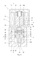
- the solenoid 7 When the solenoid 7 is energized, first, the pilot valve body 5 is raised by the clearance e1 by the suction force Fc of the solenoid 7. As a result, the second pilot passage 63 is opened, and the fluid flows from the primary passage 31 to the secondary passage 33 through the first pilot passage 61, the second pressure chamber 24 and the second pilot passage 63. As a result, the pressure Pr in the second pressure chamber 24 decreases to a pressure between the primary pressure P1 and the secondary pressure P2, and the main valve body 4 rises due to the differential pressure between the first pressure chamber 32 and the second pressure chamber 24. . As a result, the secondary passage 33 is opened.
- the main valve body 4 rises until the main valve body 4 comes into contact with the stopper 23. As the main valve body 4 is raised, the pilot valve body 5 connected to the main valve body 4 by the pin 8 is also raised by the suction force Fc of the solenoid 7.
- the distance E from the pilot valve body 5 to the fixed magnetic pole 72 can be separated from the main valve body 4 when the second pilot passage 63 and the secondary passage 33 are closed. Is set larger than the sum of the gap e1 and the distance e2 from the main valve body 4 to the stopper 23 (E> e1 + e2). For this reason, even when the main valve body 4 abuts against the stopper 23, a gap is secured between the pilot valve body 5 and the fixed magnetic pole 72 as shown in FIG. In other words, the main valve body 4 can be pressed against the stopper 23 by the suction force Fc of the solenoid 7.
- the main valve body 4 is restrained to the open position even if the supply of fluid is stopped on the downstream side of the valve device 1A and the fluid no longer flows into the main passage 3. can do.
- the clearance e1 that enables the pilot valve body 5 to be separated from the main valve body 4 is much smaller than the distance e2 that is also the stroke of the main valve body 4.
- the main valve body 4 is driven in the opening direction by the differential pressure between the first pressure chamber 32 and the second pressure chamber 24.
- the pilot passage 63 is opened, the main valve body 4 is opened instantly due to a decrease in the pressure in the second pressure chamber 24. Therefore, the valve device 1A has excellent responsiveness.
- the solenoid 7 for the pilot valve body 5 only needs to have a suction force necessary to drive the pilot valve body 5 by the gap e1 between the pin 8 and the pilot valve body 5, so that the solenoid 7 can be reduced in size.
- the second pilot passage having the second throttle 64 is formed in the main valve body 4, the valve seat area of the pilot valve body 5 is reduced, and the pilot valve body 5 is opened with less driving power. Is possible. Further, since the main valve body 4 and the pilot valve body 5 are connected by the pin 8, the state where the main valve body 4 opens the secondary passage 33 can be maintained by using the suction force of the solenoid 7.
- the sealing member mounted on the main valve body 4 is a flat ring that slides with the peripheral surface of the first sliding chamber 20a, and has an oblique cut so that it can be enlarged when mounted as shown in FIG. It is also possible to use a bias cut type flat ring 96 that is formed and an elastic body that biases the flat ring 96 radially outward.
- a bias cut type flat ring 96 that is formed and an elastic body that biases the flat ring 96 radially outward.
- the seal member 9 including the spiral ring 92 is used as in the present embodiment, the distance at which the surrounding portions 95 of the spiral ring 92 overlap is relatively long. Even if it is not strictly controlled, sufficient sealing performance can be secured. Therefore, it is not necessary to manage the dimensions after mounting like the flat ring 96, and the manufacturing cost can be reduced.
- the distance E from the pilot valve body 5 to the fixed magnetic pole 72 is a clearance e1 that allows the pilot valve body 5 to be separated from the main valve body 4 and a distance e2 from the main valve body 4 to the stopper 23. It was set larger than the sum (E> e1 + e2). However, even if E ⁇ e1 + e2 (including e2 ⁇ E or the case where there is no stopper 23), the pilot valve body 5 comes into contact with the fixed magnetic pole 72 by energizing the solenoid 7, and the pilot valve body 5 and the pin The main valve body 4 connected by 8 can maintain an open position.
- the position of the main valve body 4 may change by a slight gap between the pin 8 and the lateral hole 56.
- E> e1 + e2 the suction force Fc of the solenoid 7 can be applied to the main valve body 4 located at the open position. Thereby, the position fluctuation
- This modification can also be applied to second to fourth embodiments described later.
- the seal member 9 does not necessarily include the elastic body 91 that urges the spiral ring 92 outward in the radial direction.
- the elastic body 91 can be omitted. This modification is also applicable to the second to fourth embodiments described later.
- valve device 1B Referring to a second embodiment of the present invention
- the same components as those in the first embodiment are denoted by the same reference numerals, and redundant description is omitted.
- the lateral hole 56 provided in the pilot valve body 5 is fitted to the pin 8 without a gap, and the pilot valve body 5 is interposed between the support hole 43 provided in the main valve body 4 and the pin 8.
- a gap e1 that allows separation from the main valve body 4 is formed.
- a valve device 1C according to a third embodiment of the present invention will be described.
- a first pilot passage 61 having a first throttle 62 is formed in the main valve body 4, and the upstream end of the first pilot passage 61 communicates with the primary passage 31 indirectly through the first pressure chamber 32. is doing.
- a plurality of first pilot passages 61 may be formed around the shaft portion 41 of the main valve body 4.
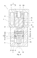
- a valve device 1D according to a fourth embodiment of the present invention will be described with reference to FIG.
- a first pilot passage 61 having a first aperture 62 is formed in the fixed magnetic pole 72.
- This embodiment assumes that almost the entire valve device 1D is inserted into a gas tank (not shown). That is, the upstream end of the first pilot passage 61 indirectly communicates with the primary passage 31 through the internal space of the gas tank.
- a flat ring 97 that slides with the peripheral surface of the first sliding chamber 20a as shown in FIG. 9 may be used instead of the spiral ring 92.
- the flat ring 97 has a stepped shape so that both ends 98 and 99 of the wire extending in the circumferential direction of the flat ring 97 are in surface contact with each other on a plane perpendicular to the axial direction of the flat ring 97. is there.
- both end portions 98 and 99 of the wire are cut out from the other side so as to engage with each other.
- both end portions 98 and 99 of the wire may extend in the circumferential direction of the flat ring 97 at half the height of the intermediate portion of the wire. In this configuration as well, the same effect as when the spiral ring 92 is used can be obtained.
- the flat ring 97 may be urged radially outward by the elastic body 91, or the elastic body 91 may be omitted.
- the present invention is widely applicable to valve devices for various uses.
- Valve device 2 Housing 20 Valve body space 23 Stopper 24 Second pressure chamber 3 Main passage 31 Primary passage 32 First pressure chamber 33 Secondary passage 4 Main valve body 5 Pilot valve body 55 Energizing member 61 First pilot passage 62 First throttle 63 Second pilot passage 64 Second throttle 7 Solenoid 8 Pin 9 Seal member 91 Elastic body 92 Spiral ring 93, 94 End portion 95 Circumferential portion 97 Flat ring 98, 99 End portion e1 Crevice
Landscapes
- Engineering & Computer Science (AREA)
- General Engineering & Computer Science (AREA)
- Mechanical Engineering (AREA)
- Chemical & Material Sciences (AREA)
- Analytical Chemistry (AREA)
- Chemical Kinetics & Catalysis (AREA)
- General Chemical & Material Sciences (AREA)
- Oil, Petroleum & Natural Gas (AREA)
- Combustion & Propulsion (AREA)
- Magnetically Actuated Valves (AREA)
- Fluid-Driven Valves (AREA)
Abstract
弁装置は、ハウジング(2)の弁体空間を第1圧力室(32)と第2圧力室(24)とに仕切る主弁体(4)と、第1圧力室(32)と第2圧力室(24)とを隔離するシール部材(9)と、一端が一次通路と直接的または間接的に連通し、他端が第2圧力室(24)と連通する、第1絞り(62)を有する第1パイロット通路(61)と、主弁体(4)に形成された、第2絞り(64)を有する第2パイロット通路(63)と、第2パイロット通路(63)を開閉するパイロット弁体(5)と、通電によりパイロット弁体(5)を付勢部材(55)の付勢力に抗して第2パイロット通路(63)を開く方向に駆動する駆動機構と、主弁体(4)とパイロット弁体(5)とを連結するピン(8)と、を備え、主弁体(4)が、第1圧力室(32)と第2圧力室(24)の差圧によって二次通路(33)を開く方向に駆動されるように構成されており、シール部材(9)は、ハウジングと摺動するスパイラルリング・フラットリングを含む。
Description
本発明は、例えば空圧用の制御機器やガスタンクの閉栓などとして用いられる弁装置に関する。
例えば高圧環境下で作動する弁装置としては、ハウジングに形成された主通路を遮断または開放する主弁体と、主弁体の開閉動作を操作するパイロット弁体を備えたものが知られている。例えば、特許文献1には、主弁体とパイロット弁体が同軸上に配置された弁装置が開示されている。
図10に、特許文献1に開示された弁装置100の一部を示す。この弁装置100では、ハウジング110に、主通路120を構成する一次通路121、圧力室122および二次通路123が形成されており、二次通路123が主弁体140によって開閉される。主弁体140を挟んで圧力室122と反対側にはパイロット室130が形成されており、このパイロット室130は、主弁体140とハウジング110の間の隙間である第1パイロット通路131を通じて圧力室122と連通している。また、主弁体140には、第2パイロット通路132が形成されており、この第2パイロット通路132は、パイロット弁体150によって開閉される。パイロット弁体150は、図略のソレノイドにより駆動される。
さらに、弁装置100では、主弁体140とパイロット弁体150がピン160で連結されている。ピン160はパイロット弁体150に設けられた横穴とは隙間なく嵌合しているものの、ピン160と主弁体140に設けられた支持穴141との間には隙間が形成されており、パイロット弁体150はその隙間分だけ主弁体140から離間できるようになっている。
パイロット弁体150は、図略のばねによって主弁体140に押し付けられている。図略のソレノイドに通電されると、まずパイロット弁体150が支持穴141とピン160の間の隙間分だけ主弁体140から離間する。これにより、第2パイロット通路132が開かれる。その後、パイロット室130と二次通路123の差圧が小さくなって、ソレノイドによるパイロット弁体150の吸引力がパイロット弁体150を付勢するばねの付勢力およびパイロット室130の圧力に打ち勝つと、主弁体140が引き上げられる。これにより、二次通路123が開かれる。
しかしながら、特許文献1に開示された弁装置100のように、ソレノイドの吸引力により主弁体140を開方向に駆動する構成では、ソレノイドの吸引力がパイロット弁体150を付勢するばねの付勢力およびパイロット室130の圧力に打ち勝つまでにある程度の時間を要し、応答性がよくない。また、ソレノイドは主弁体140を引き上げるために大きな吸引力を有する必要があるため、ソレノイドを小型化することが困難である。
そこで、本発明は、パイロット弁体用の駆動機構を小型化でき、かつ、応答性に優れた弁装置を提供することを目的とする。
前記課題を解決するために、本発明の弁装置は、主通路を構成する一次通路および二次通路が形成された、前記一次通路と前記二次通路の間に弁体空間を有するハウジングと、前記弁体空間を前記一次通路および前記二次通路と連通する第1圧力室と第2圧力室とに仕切るように前記ハウジング内に配置された、前記二次通路を開閉する主弁体と、前記主弁体に設けられた環状溝であって前記ハウジングで覆われる環状溝内に配置された、前記第1圧力室と前記第2圧力室とを隔離するシール部材と、一端が前記一次通路と直接的または間接的に連通し、他端が前記第2圧力室と連通する、第1絞りを有する第1パイロット通路と、前記第2圧力室から前記二次通路へ至るように前記主弁体に形成された、第2絞りを有する第2パイロット通路と、前記第2圧力室内に配置された、前記第2パイロット通路を開閉するパイロット弁体と、前記パイロット弁体を前記主弁体に押し付ける付勢部材と、通電により前記パイロット弁体を前記付勢部材の付勢力に抗して前記第2パイロット通路を開く方向に駆動する駆動機構と、前記主弁体と前記パイロット弁体とを連結するピンであって、前記主弁体または前記パイロット弁体との間に前記パイロット弁体の前記主弁体からの離間を可能とする隙間が形成されたピンと、を備え、前記主弁体が、前記パイロット弁体により前記第2パイロット通路が開かれて前記第2圧力室の圧力が前記第1圧力室の圧力よりも低下したときに、前記第1圧力室と前記第2圧力室の差圧によって前記二次通路を開く方向に駆動されるように構成されており、前記シール部材は、前記ハウジングと摺動するスパイラルリングを含む、ことを特徴とする。
上記の構成によれば、主弁体が第1圧力室と第2圧力室の差圧によって開方向に駆動されるため、パイロット弁体により第2パイロット通路が開かれれば、第2圧力室の圧力の低下により主弁体が瞬時に開動作する。従って、弁装置は優れた応答性を有する。しかも、パイロット弁体用の駆動機構は、ピンと主弁体またはパイロット弁体との間の隙間分だけパイロット弁体を駆動させるのに必要なパワーを有すればよいため、駆動機構を小型化することができる。さらには、主弁体に第2絞りを有する第2パイロット通路が形成されているため、パイロット弁体の弁座面積を小さくして、より小さな駆動パワーでパイロット弁体の開動作が可能となる。また、主弁体とパイロット弁体とがピンにより連結されているので、駆動機構のパワーを利用して、主弁体が二次通路を開いた状態を保持できる。
ところで、主弁体に装着されるシール部材としては、ハウジングと摺動するフラットリングであって装着時に拡大できるように斜めの切り込みが形成されたバイアスカット型のフラットリングと、そのフラットリングを径方向外向きに付勢する弾性体を含むものを用いることも可能である。しかしながら、この場合には、第1圧力室と第2圧力室の差圧を安定して発生させるために、装着後のフラットリングの切り込みの寸法を厳密に管理する必要がある。これに対し、本発明のようにスパイラルリングを含むシール部材を用いれば、スパイラルリングの周回部分同士が重なり合う距離が比較的に長いため、それらの周回部分同士の間の隙間を厳密に管理しなくても十分なシール性を確保することができる。従って、フラットリングのような装着後の寸法の管理が不要となり、製造コストを削減することができる。
前記スパイラルリングは、1本の線材が当該線材の少なくとも両端部が周回部分と重なり合うように巻き回されたものであり、前記線材の両端部は、前記周回部分との間に楔状の隙間が形成されるように先細りとなっていてもよい。この構成によれば、スパイラルリングを主弁体の環状溝に嵌め込むときに、線材の両端部間で周回部分を両端部の形状に沿って滑らかに変形させることができ、スパイラルリングを簡単にフラットにすることができる。
例えば、前記シール部材は、前記スパイラルリングを径方向外向きに付勢する弾性体を含んでもよい。
前記スパイラルリングに代えて、前記ハウジングと摺動するフラットリングであって、前記フラットリングの周方向に延びる線材における互いに重なり合う両端部が前記フラットリングの軸方向と直交する平面上で互いに面接触するように段差形状とされたフラットリングが用いられてもよい。この構成においても、スパイラルリングを用いた場合と同様の効果を得ることができる。例えば、前記シール部材は、前記フラットリングを径方向外向きに付勢する弾性体を含んでもよい。
前記駆動機構は、前記パイロット弁体を吸引する固定磁極を含むソレノイドであり、前記ハウジングには、前記主弁体用のストッパーが設けられており、前記第2パイロット通路および前記二次通路が閉じられた状態において、前記パイロット弁体から前記固定磁極までの距離は、前記主弁体から前記ストッパーまでの距離と前記隙間の和よりも大きくてもよい。この構成によれば、ソレノイドに通電されている間は、ソレノイドの吸引力によって主弁体をストッパーに押し付けることができる。
前記第1パイロット通路が前記ハウジングまたは前記主弁体に形成されていてもよい。この構成によれば、第1絞りを機械加工によって高精度に成形することができる。
本発明によれば、パイロット弁体用の駆動機構を小型化でき、かつ、応答性に優れた弁装置を提供できる。
(第1実施形態)
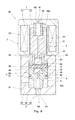
図1および図2に、本発明の第1実施形態に係る弁装置1Aを示す。弁装置1Aは、空圧用の制御機器やガスタンクの閉栓などとして用いられる。弁装置1Aが対象とする流体は、例えば高圧ガスである。
図1および図2に、本発明の第1実施形態に係る弁装置1Aを示す。弁装置1Aは、空圧用の制御機器やガスタンクの閉栓などとして用いられる。弁装置1Aが対象とする流体は、例えば高圧ガスである。
本実施形態の弁装置1Aは、電磁弁である。具体的に、弁装置1Aは、ハウジング2と、ハウジング2内に配置された主弁体4およびパイロット弁体5と、パイロット弁体5を駆動するソレノイド(駆動機構)7を備える。弁装置1Aがガスタンクの閉栓として用いられる場合は、ソレノイド7を含む弁装置1Aのほぼ全体がガスタンク内に挿入されてもよい。
ただし、弁装置1Aは、駆動機構としてソレノイド7が採用された電磁弁に限定されるものではない。例えば、駆動機構としては、圧電アクチュエータを使用してもよい。圧電アクチュエータは、圧電素子(例えば、ピエゾ素子)を含み、印加される電圧に応じた駆動力を発生する。あるいは、駆動機構としては、フォースモータを使用してもよい。フォースモータは、円筒状の永久磁石の中に可動コイルが挿入されており、可動コイルに電流を流すと電流に応じた励磁力が発生し、この励磁力により可動コイルが動くようになっている。
主弁体4およびパイロット弁体5は共に断面円形状の棒状部材であり、それらの中心軸は同一直線上に位置している。換言すれば、主弁体4とパイロット弁体5は同軸上に配置されている。なお、以下では、説明の便宜上、主弁体4とパイロット弁体5が並ぶ方向(主弁体4およびパイロット弁体5の軸方向)を上下方向(パイロット弁体5側を上方、主弁体4側を下方)という。ただし、主弁体4とパイロット弁体5が並ぶ方向は、水平方向や斜め方向であってもよいことは言うまでもない。
ハウジング2は、主通路3を構成する一次通路31および二次通路33が形成された第1本体21と、ソレノイド7が組み込まれた第2本体22を含む。また、ハウジング2は、一次通路31と二次通路33の間に弁体空間20を有する。弁体空間20は、第1本体21と第2本体22に跨って延びている。
より詳しくは、第1本体21には、主弁体4を上下方向に摺動可能に保持する円筒状の第1摺動室20aが形成されており、第2本体22には、パイロット弁体5を上下方向に摺動可能に保持する円筒状の第2摺動室20bが形成されている。また、第1本体21には、第1摺動室20aと第2摺動室20bの間で径方向内側に突出し、上方に移動する主弁体4を当て止めるストッパー23が設けられている。上述した弁体空間20は、第1摺動室20a、ストッパー23および第2摺動室20bで規定される連続した空間である。
一次通路31の一端(上流端)は第1本体21の側面に開口し、他端(下流端)は第1摺動室20aの周面に開口している。一方、二次通路33の一端(上流端)は第1摺動室20aの底面に開口し、他端(下流端)は第1本体21の下面に開口している。そして、第1摺動室20aの底面には、二次通路33の上流端の周囲に、主弁体4用の第1弁座25が形成されている。
主弁体4は、ハウジング2内に、弁体空間20を一次通路31および二次通路33と連通する第1圧力室32と第2圧力室24とに仕切るように配置されている。第1圧力室32は、一次通路31および二次通路33と共に主通路3を構成する。
より詳しくは、主弁体4は、第1摺動室20aの周面の直径よりも小径の軸部41と、軸部41の上側の周縁部から上向きに延びる、第1摺動室20aの周面の直径とほぼ等しい外径の筒状部42とを有する。筒状部42は第1摺動室20aに摺動可能に保持される部分である。すなわち、第1圧力室32は、第1摺動室20aの周面のうちの筒状部42よりも下側の部分と軸部41の外周面との間に規定される。一方、第2圧力室24は、軸部41の上面および筒状部42の内周面に面する空間、第1摺動室20aのうちの主弁体4よりも上側の領域、ストッパー23の内部ならびに第2摺動室20bで構成される。
主弁体4の筒状部42には、第1圧力室32と第2圧力室24とを隔離するシール部材9が装着されている。具体的に、筒状部42の外周面には、径方向外向きに開口し、第1摺動室20aの周面で覆われる環状溝が設けられている。シール部材9は、この環状溝内に配置されている。シール部材9については、後述にて詳細に説明する。
主弁体4は、軸部41が第1弁座25に着座する閉位置と、筒状部42がストッパー23に当接する開位置との間で移動し、二次通路33を開閉する。軸部41が第1弁座25に着座すると、二次通路33が閉じられて第1圧力室32が二次通路33から隔離され、軸部41が第1弁座25から離間すると、二次通路33が開かれて第1圧力室32が二次通路33と接続される。
本実施形態では、ハウジング2の第1本体21に、第1パイロット通路61が形成されている。第1パイロット通路61の一端(上流端)は一次通路31と直接的に連通しており、第1パイロット通路61の他端(下流端)は第2圧力室24と連通している。第1パイロット通路61には、中間に第1絞り62が設けられている。
一方、主弁体4には、第2圧力室24から二次通路33へ至るように第2パイロット通路63が形成されている。第2パイロット通路63は主弁体4の中心軸上に配置されており、第2パイロット通路63の一端(上流端)は軸部41の上面に開口し、他端(下流端)は軸部41の先端面に開口している。第2パイロット通路63には、第2圧力室24側の端部に第2絞り64が設けられている。第2パイロット通路63は、パイロット弁体5により開閉される。
パイロット弁体5は、第2圧力室24内に配置されている。また、第2圧力室24内には、パイロット弁体5を主弁体4に押し付ける付勢部材55が配置されている。付勢部材55は、例えば圧縮コイルばねである。
パイロット弁体5には、当該パイロット弁体5によって第2圧力室24が上下に分断されることを回避するために、中心軸上の縦穴53と、この縦穴53の下端と交わる横穴54が形成されている。これらの縦穴53および横穴54により、第2圧力室24においてパイロット弁体5の下側空間と上側空間とが連通している。
より詳しくは、パイロット弁体5は、第2摺動室20bに摺動可能に保持される本体部51と、本体部51から下方に突出して主弁体4の筒状部42内に挿入される軸部52とを有している。
主弁体4の軸部41の上面には、第2パイロット通路63の上流端の周囲に、パイロット弁体5用の第2弁座45が形成されている。軸部52が第2弁座45に着座すると、第2パイロット通路63が閉じられて第2圧力室24が第2パイロット通路63から隔離され、軸部52が第2弁座45から離間すると、第2パイロット通路63が開かれて第2圧力室24が第2パイロット通路63と接続される。なお、第2圧力室24内では、パイロット弁体5の軸部52が第2弁座45から離間すると、主弁体4の筒状部42の内周面とパイロット弁体5の軸部52の外周面との間の隙間、および主弁体4の軸部41の上面とパイロット弁体5の軸部52の先端面との間の隙間を通じて、流体が第2パイロット通路63の上流端に導かれる。
上述したソレノイド7は、通電によりパイロット弁体5を付勢部材55の付勢力に抗して第2パイロット通路63を開く方向に駆動する。すなわち、パイロット弁体5は、ソレノイド7により駆動される可動鉄心としても機能する。ソレノイド7は、第2摺動室20bの回りに巻き回されたコイル71と、パイロット弁体5の上方に配置された、パイロット弁体5を吸引する固定磁極72を含む。固定磁極72は、ハウジング2の第2本体22の一部でもある。
パイロット弁体5の軸部52と主弁体4の筒状部42とは、上下方向と直交する水平方向に延びるピン8によって連結されている。パイロット弁体5の軸部52には、ピン8に挿通される横穴56が形成されており、主弁体4の筒状部42には、ピン8の両端部を支持する支持穴43が形成されている。本実施形態では、支持穴43がピン8と隙間なく嵌合しており、パイロット弁体5が主弁体4に当接した状態のピン8の下方においてピン8と横穴56との間に隙間e1が形成されている。このため、パイロット弁体5は、その隙間e1分だけ主弁体4から離間することができる(図2参照)。横穴56は、ピン8よりも大径の円形穴であってもよいし、ピン8の直径と同一幅で上下方向に延びる長穴であってもよい。
第2パイロット通路63が閉じられているとき、第2圧力室24の圧力Prは、一次通路31の圧力である一次圧力P1と等しい。パイロット弁体5を隙間e1だけ駆動するために、ソレノイド7は、二次通路33の圧力である二次圧力をP2、第2弁座45の面積をAp、付勢部材55の付勢力をFsとしたときに、Fs+Ap(P1-P2)よりも大きい吸引力Fcを有する。
主弁体4は、パイロット弁体5により第2パイロット通路63が開かれて第2圧力室24の圧力が第1圧力室32の圧力よりも低下したときに、第1圧力室32と第2圧力室24の差圧によって二次通路33を開く方向に駆動されるように構成されている。具体的には、第1摺動室20aの断面積をA1、第1弁座25の面積をAmとしたときに、以下の式
(P1-Pr)(A1-Am)>(Pr-P2)Am
を満たすように、第1絞り62および第2絞り64ならびに面積A1,Amが設定されている。
(P1-Pr)(A1-Am)>(Pr-P2)Am
を満たすように、第1絞り62および第2絞り64ならびに面積A1,Amが設定されている。
上述したシール部材9は、第1摺動室20aの周面と摺動するスパイラルリング92と、スパイラルリング92を径方向外向きに付勢する環状の弾性体91を含む。弾性体91は、例えば略四角形状や断面円形状のゴムリングである。
スパイラルリング92は、図3Aに示すように、1本の線材が当該線材の少なくとも両端部93,94がスパイラルリング92の軸方向において周回部分95と重なり合うように巻き回されたものである。つまり、スパイラルリング92は、主弁体4の筒状部42の環状溝に嵌め込まれる前、換言すれば自然体では、線材の両端部93,94がスパイラルリング92の軸方向に突出する形状を有している。本実施形態では、線材が略2周巻き回されているが、線材は略1.5周巻き回されていてもよいし、略3周巻き回されていてもよい。スパイラルリング92は、径方向や軸方向に押し潰し可能(変形可能)なように、比較的に柔らかい材質(例えば、樹脂)で構成されている。スパイラルリング92を比較的柔らかい材質で構成することにより、スパイラルリング92を径方向に押し潰すことによって、シール性を確保することができ、また、軸方向に押し潰すことによって、主弁体4の筒状部42の環状溝に収まる形状に変形させることができる。更に、スパイラルリング92を樹脂で構成することにより、ゴム製と比較して、摺動性の向上を図れる。
線材の両端部93,94は、周回部分95との間に楔状の隙間が形成されるように先細りとなっている。換言すれば、両端部93,94には、周回部分95を挟んで互いに対向するように(換言すれば、先端からその近傍位置に向かって周回部分95に近づくように)傾斜する傾斜面が形成されている。このため、スパイラルリング92を主弁体4の筒状部42の環状溝に嵌め込むときに、図3Bに示すように、線材の両端部93,94間で周回部分95を両端部93,94の形状に沿って滑らかに変形させることができ、スパイラルリング92を簡単にフラットにすることができる。
次に、弁装置1Aの動作を説明する。まず、図1に示すように、主弁体4が閉位置に位置する状態から説明する。
ソレノイド7に通電されていないときは、付勢部材55によりパイロット弁体5が主弁体4に押し付けられて、第2パイロット通路63が閉じられる。すなわち、第2パイロット通路63の圧力は二次圧力P2と等しく、第1パイロット通路61および第2圧力室24の圧力は一次圧力P1と等しい。このため、パイロット弁体5の軸部52は、付勢部材55の付勢力Fsおよび第2圧力室24と第2パイロット通路63の差圧に応じた押付力(Ap(P1-P2))により第2弁座45に押し付けられている。一方、主弁体4の軸部41は、付勢部材55の付勢力Fsおよび第2圧力室24と二次通路33の差圧に応じた押付力(Am(P1-P2))により第1弁座25に押し付けられている。
ソレノイド7に通電されると、まず、ソレノイド7の吸引力Fcによりパイロット弁体5が隙間e1分だけ上昇する。これにより、第2パイロット通路63が開かれ、一次通路31から、第1パイロット通路61、第2圧力室24および第2パイロット通路63を通じて二次通路33へ流体が流れる。その結果、第2圧力室24の圧力Prが一次圧力P1と二次圧力P2の間の圧力に低下し、第1圧力室32と第2圧力室24の差圧によって主弁体4が上昇する。これにより、二次通路33が開かれる。
主弁体4は、当該主弁体4がストッパー23に当接するまで上昇する。主弁体4の上昇に伴い、主弁体4とピン8により連結されたパイロット弁体5もソレノイド7の吸引力Fcにより上昇する。
本実施形態では、第2パイロット通路63および二次通路33が閉じられた状態において、パイロット弁体5から固定磁極72までの距離Eは、パイロット弁体5の主弁体4からの離間を可能とする隙間e1と主弁体4からストッパー23までの距離e2の和よりも大きく設定されている(E>e1+e2)。このため、主弁体4がストッパー23に当接したときでも、図2に示すようにパイロット弁体5と固定磁極72の間に隙間が確保される。換言すれば、ソレノイド7の吸引力Fcによって主弁体4をストッパー23に押し付けることができる。このため、ソレノイド7に通電されている間は、たとえ弁装置1Aの下流側で流体の供給が停止されて、主通路3に流体が流れなくなったとしても、主弁体4を開位置に拘束することができる。なお、パイロット弁体5の主弁体4からの離間を可能とする隙間e1は、主弁体4のストロークでもある距離e2よりも格段に小さい。
ソレノイド7への通電が切られると、まず付勢部材55の付勢力Fsによりパイロット弁体5が第2パイロット通路63を閉じる。これにより、Pr=P1となり、主弁体4が付勢部材55の付勢力Fsおよび第2圧力室24と二次通路33の差圧より開位置から閉位置に移動する。
以上説明したように、本実施形態の弁装置1Aでは、主弁体4が第1圧力室32と第2圧力室24の差圧によって開方向に駆動されるため、パイロット弁体5により第2パイロット通路63が開かれれば、第2圧力室24の圧力の低下により主弁体4が瞬時に開動作する。従って、弁装置1Aは優れた応答性を有する。しかも、パイロット弁体5用のソレノイド7は、ピン8とパイロット弁体5の間の隙間e1分だけパイロット弁体5を駆動させるのに必要な吸引力を有すればよいため、ソレノイド7を小型化することができる。さらには、主弁体4に第2絞り64を有する第2パイロット通路が形成されているため、パイロット弁体5の弁座面積を小さくして、より小さな駆動パワーでパイロット弁体5の開動作が可能となる。また、主弁体4とパイロット弁体5とがピン8により連結されているので、ソレノイド7の吸引力を利用して、主弁体4が二次通路33を開いた状態を保持できる。
ところで、主弁体4に装着されるシール部材としては、第1摺動室20aの周面と摺動するフラットリングであって、図4に示すように装着時に拡大できるように斜めの切り込みが形成されたバイアスカット型のフラットリング96と、そのフラットリング96を径方向外向きに付勢する弾性体を含むものを用いることも可能である。しかしながら、この場合には、第1圧力室32と第2圧力室24の差圧を安定して発生させるために、装着後のフラットリング96の切り込みの寸法を厳密に管理する必要がある。これに対し、本実施形態のようにスパイラルリング92を含むシール部材9を用いれば、スパイラルリング92の周回部分95同士が重なり合う距離が比較的に長いため、それらの周回部分95同士の間の隙間を厳密に管理しなくても十分なシール性を確保することができる。従って、フラットリング96のような装着後の寸法の管理が不要となり、製造コストを削減することができる。
<変形例>
前記実施形態では、パイロット弁体5から固定磁極72までの距離Eは、パイロット弁体5の主弁体4からの離間を可能とする隙間e1と主弁体4からストッパー23までの距離e2の和よりも大きく設定されていた(E>e1+e2)。しかしながら、E≦e1+e2(e2≧E、又は、ストッパー23がない場合も含む)となっていても、ソレノイド7への通電によってパイロット弁体5が固定磁極72に当接し、パイロット弁体5とピン8によって連結された主弁体4は開位置を維持できる。ただし、その状態において、ピン8と横穴56の間の僅かな隙間分だけ、主弁体4が位置変動するおそれがある。これに対し、E>e1+e2となっていれば、開位置に位置した主弁体4にソレノイド7の吸引力Fcを作用させることができる。これにより、そのような主弁体4の位置変動を防止することができる。なお、本変形例は、後述する第2~第4実施形態においても適用可能である。
前記実施形態では、パイロット弁体5から固定磁極72までの距離Eは、パイロット弁体5の主弁体4からの離間を可能とする隙間e1と主弁体4からストッパー23までの距離e2の和よりも大きく設定されていた(E>e1+e2)。しかしながら、E≦e1+e2(e2≧E、又は、ストッパー23がない場合も含む)となっていても、ソレノイド7への通電によってパイロット弁体5が固定磁極72に当接し、パイロット弁体5とピン8によって連結された主弁体4は開位置を維持できる。ただし、その状態において、ピン8と横穴56の間の僅かな隙間分だけ、主弁体4が位置変動するおそれがある。これに対し、E>e1+e2となっていれば、開位置に位置した主弁体4にソレノイド7の吸引力Fcを作用させることができる。これにより、そのような主弁体4の位置変動を防止することができる。なお、本変形例は、後述する第2~第4実施形態においても適用可能である。
また、シール部材9は、必ずしもスパイラルリング92を径方向外向きに付勢する弾性体91を含んでいる必要はない。例えば、スパイラルリング92を自然体での外径が第1摺動室20aの周面の直径よりも大きくなるように構成すれば、弾性体91を省略することも可能である。この変形例も、後述する第2~第4実施形態に適用可能である。
(第2実施形態)
次に、図5を参照して、本発明の第2実施形態に係る弁装置1Bを説明する。なお、本実施形態および後述する第3および第4実施形態において、第1実施形態と同一構成要素には同一符号を付し、重複した説明は省略する。
次に、図5を参照して、本発明の第2実施形態に係る弁装置1Bを説明する。なお、本実施形態および後述する第3および第4実施形態において、第1実施形態と同一構成要素には同一符号を付し、重複した説明は省略する。
本実施形態では、パイロット弁体5に設けられた横穴56がピン8と隙間なく嵌合しており、主弁体4に設けられた支持穴43とピン8との間にパイロット弁体5の主弁体4からの離間を可能とする隙間e1が形成されている。
このような構成であっても、第1実施形態と同様の効果を得ることができる。
(第3実施形態)
次に、図6を参照して、本発明の第3実施形態に係る弁装置1Cを説明する。本実施形態では、第1絞り62を有する第1パイロット通路61が主弁体4に形成されており、第1パイロット通路61の上流端が第1圧力室32を通じて間接的に一次通路31と連通している。なお、図7に示すように、第1パイロット通路61は、主弁体4の軸部41の回りに複数形成されていてもよい。
次に、図6を参照して、本発明の第3実施形態に係る弁装置1Cを説明する。本実施形態では、第1絞り62を有する第1パイロット通路61が主弁体4に形成されており、第1パイロット通路61の上流端が第1圧力室32を通じて間接的に一次通路31と連通している。なお、図7に示すように、第1パイロット通路61は、主弁体4の軸部41の回りに複数形成されていてもよい。
このような構成であっても、第1実施形態と同様の効果を得ることができる。
(第4実施形態)
次に、図8を参照して、本発明の第4実施形態に係る弁装置1Dを説明する。本実施形態では、第1絞り62を有する第1パイロット通路61が固定磁極72に形成されている。
次に、図8を参照して、本発明の第4実施形態に係る弁装置1Dを説明する。本実施形態では、第1絞り62を有する第1パイロット通路61が固定磁極72に形成されている。
本実施形態は、弁装置1Dのほぼ全体がガスタンク(図示せず)内に挿入されることを想定したものである。すなわち、ガスタンクの内部空間を通じて、第1パイロット通路61の上流端が間接的に一次通路31と連通する。
このような構成であっても、第1実施形態と同様の効果を得ることができる。
(その他の実施形態)
本発明は上述した第1~第4実施形態に限定されるものではなく、本発明の要旨を逸脱しない範囲で種々の変形が可能である。
本発明は上述した第1~第4実施形態に限定されるものではなく、本発明の要旨を逸脱しない範囲で種々の変形が可能である。
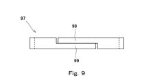
例えば、第1~第4実施形態において、スパイラルリング92に代えて、図9に示すような、第1摺動室20aの周面と摺動するフラットリング97が用いられてもよい。このフラットリング97は、当該フラットリング97の周方向に延びる線材における互いに重なり合う両端部98,99がフラットリング97の軸方向と直交する平面上で互いに面接触するように段差形状とされたものである。換言すれば、線材の両端部98,99は、互いに係合するように相手側から切り欠かれている。例えば、線材の両端部98,99は、線材の中間部の半分の高さでフラットリング97の周方向に延びてもよい。この構成においても、スパイラルリング92を用いた場合と同様の効果を得ることができる。
フラットリング97を用いた場合でも、弾性体91によってフラットリング97を径方向外向きに付勢してもよいし、弾性体91を省略してもよい。
本発明は、種々の用途の弁装置に広く適用可能である。
1A~1E 弁装置
2 ハウジング
20 弁体空間
23 ストッパー
24 第2圧力室
3 主通路
31 一次通路
32 第1圧力室
33 二次通路
4 主弁体
5 パイロット弁体
55 付勢部材
61 第1パイロット通路
62 第1絞り
63 第2パイロット通路
64 第2絞り
7 ソレノイド
8 ピン
9 シール部材
91 弾性体
92 スパイラルリング
93,94 端部
95 周回部分
97 フラットリング
98,99 端部
e1 隙間
2 ハウジング
20 弁体空間
23 ストッパー
24 第2圧力室
3 主通路
31 一次通路
32 第1圧力室
33 二次通路
4 主弁体
5 パイロット弁体
55 付勢部材
61 第1パイロット通路
62 第1絞り
63 第2パイロット通路
64 第2絞り
7 ソレノイド
8 ピン
9 シール部材
91 弾性体
92 スパイラルリング
93,94 端部
95 周回部分
97 フラットリング
98,99 端部
e1 隙間
Claims (9)
- 主通路を構成する一次通路および二次通路が形成された、前記一次通路と前記二次通路の間に弁体空間を有するハウジングと、
前記弁体空間を前記一次通路および前記二次通路と連通する第1圧力室と第2圧力室とに仕切るように前記ハウジング内に配置された、前記二次通路を開閉する主弁体と、
前記主弁体に設けられた環状溝であって前記ハウジングで覆われる環状溝内に配置された、前記第1圧力室と前記第2圧力室とを隔離するシール部材と、
一端が前記一次通路と直接的または間接的に連通し、他端が前記第2圧力室と連通する、第1絞りを有する第1パイロット通路と、
前記第2圧力室から前記二次通路へ至るように前記主弁体に形成された、第2絞りを有する第2パイロット通路と、
前記第2圧力室内に配置された、前記第2パイロット通路を開閉するパイロット弁体と、
前記パイロット弁体を前記主弁体に押し付ける付勢部材と、
通電により前記パイロット弁体を前記付勢部材の付勢力に抗して前記第2パイロット通路を開く方向に駆動する駆動機構と、
前記主弁体と前記パイロット弁体とを連結するピンであって、前記主弁体または前記パイロット弁体との間に前記パイロット弁体の前記主弁体からの離間を可能とする隙間が形成されたピンと、を備え、
前記主弁体が、前記パイロット弁体により前記第2パイロット通路が開かれて前記第2圧力室の圧力が前記第1圧力室の圧力よりも低下したときに、前記第1圧力室と前記第2圧力室の差圧によって前記二次通路を開く方向に駆動されるように構成されており、
前記シール部材は、前記ハウジングと摺動するスパイラルリングを含む、弁装置。 - 前記スパイラルリングは、1本の線材が当該線材の少なくとも両端部が周回部分と重なり合うように巻き回されたものであり、前記線材の両端部は、前記周回部分との間に楔状の隙間が形成されるように先細りとなっている、請求項1に記載の弁装置。
- 前記シール部材は、前記スパイラルリングを径方向外向きに付勢する弾性体を含む、請求項1または2に記載の弁装置。
- 前記駆動機構は、前記パイロット弁体を吸引する固定磁極を含むソレノイドであり、
前記ハウジングには、前記主弁体用のストッパーが設けられており、
前記第2パイロット通路および前記二次通路が閉じられた状態において、前記パイロット弁体から前記固定磁極までの距離は、前記主弁体から前記ストッパーまでの距離と前記隙間の和よりも大きい、請求項1~3のいずれか一項に記載の弁装置。 - 前記第1パイロット通路が前記ハウジングまたは前記主弁体に形成されている、請求項1~4のいずれか一項に記載の弁装置。
- 主通路を構成する一次通路および二次通路が形成された、前記一次通路と前記二次通路の間に弁体空間を有するハウジングと、
前記弁体空間を前記一次通路および前記二次通路と連通する第1圧力室と第2圧力室とに仕切るように前記ハウジング内に配置された、前記二次通路を開閉する主弁体と、
前記主弁体に設けられた環状溝であって前記ハウジングで覆われる環状溝内に配置された、前記第1圧力室と前記第2圧力室とを隔離するシール部材と、
一端が前記一次通路と直接的または間接的に連通し、他端が前記第2圧力室と連通する、第1絞りを有する第1パイロット通路と、
前記第2圧力室から前記二次通路へ至るように前記主弁体に形成された、第2絞りを有する第2パイロット通路と、
前記第2圧力室内に配置された、前記第2パイロット通路を開閉するパイロット弁体と、
前記パイロット弁体を前記主弁体に押し付ける付勢部材と、
通電により前記パイロット弁体を前記付勢部材の付勢力に抗して前記第2パイロット通路を開く方向に駆動する駆動機構と、
前記主弁体と前記パイロット弁体とを連結するピンであって、前記主弁体または前記パイロット弁体との間に前記パイロット弁体の前記主弁体からの離間を可能とする隙間が形成されたピンと、を備え、
前記主弁体が、前記パイロット弁体により前記第2パイロット通路が開かれて前記第2圧力室の圧力が前記第1圧力室の圧力よりも低下したときに、前記第1圧力室と前記第2圧力室の差圧によって前記二次通路を開く方向に駆動されるように構成されており、
前記シール部材は、前記ハウジングと摺動するフラットリングであって、前記フラットリングの周方向に延びる線材における互いに重なり合う両端部が前記フラットリングの軸方向と直交する平面上で互いに面接触するように段差形状とされたフラットリングを含む、弁装置。 - 前記シール部材は、前記フラットリングを径方向外向きに付勢する弾性体を含む、請求項6に記載の弁装置。
- 前記駆動機構は、前記パイロット弁体を吸引する固定磁極を含むソレノイドであり、
前記ハウジングには、前記主弁体用のストッパーが設けられており、
前記第2パイロット通路および前記二次通路が閉じられた状態において、前記パイロット弁体から前記固定磁極までの距離は、前記主弁体から前記ストッパーまでの距離と前記隙間の和よりも大きい、請求項6または7に記載の弁装置。 - 前記第1パイロット通路が前記ハウジングまたは前記主弁体に形成されている、請求項6~8のいずれか一項に記載の弁装置。
Priority Applications (1)
| Application Number | Priority Date | Filing Date | Title |
|---|---|---|---|
| US15/551,297 US10161360B2 (en) | 2015-02-26 | 2016-02-23 | Valve device |
Applications Claiming Priority (2)
| Application Number | Priority Date | Filing Date | Title |
|---|---|---|---|
| JP2015-036636 | 2015-02-26 | ||
| JP2015036636A JP6463647B2 (ja) | 2015-02-26 | 2015-02-26 | 弁装置 |
Publications (1)
| Publication Number | Publication Date |
|---|---|
| WO2016136239A1 true WO2016136239A1 (ja) | 2016-09-01 |
Family
ID=56788326
Family Applications (1)
| Application Number | Title | Priority Date | Filing Date |
|---|---|---|---|
| PCT/JP2016/000955 Ceased WO2016136239A1 (ja) | 2015-02-26 | 2016-02-23 | 弁装置 |
Country Status (3)
| Country | Link |
|---|---|
| US (1) | US10161360B2 (ja) |
| JP (1) | JP6463647B2 (ja) |
| WO (1) | WO2016136239A1 (ja) |
Cited By (3)
| Publication number | Priority date | Publication date | Assignee | Title |
|---|---|---|---|---|
| WO2019001249A1 (zh) * | 2017-06-30 | 2019-01-03 | 浙江三花汽车零部件有限公司 | 一种电动阀 |
| JP2021017948A (ja) * | 2019-07-22 | 2021-02-15 | 日本電産トーソク株式会社 | 電磁弁、および流路装置 |
| JP2021110442A (ja) * | 2020-01-15 | 2021-08-02 | 日立Astemo株式会社 | バルブ機構および圧力緩衝装置 |
Families Citing this family (28)
| Publication number | Priority date | Publication date | Assignee | Title |
|---|---|---|---|---|
| DE102015005977A1 (de) * | 2015-05-08 | 2016-11-10 | Daimler Ag | Entnahmeventil |
| KR101821597B1 (ko) * | 2016-05-10 | 2018-01-26 | 영도산업 주식회사 | 유체 제어용 솔레노이드 밸브 |
| KR102274114B1 (ko) * | 2017-01-25 | 2021-07-06 | 현대자동차주식회사 | 독립 거동 가능한 파일럿 플런저 헤드를 포함하는 솔레노이드 밸브 |
| DE102018113748B3 (de) * | 2018-06-08 | 2019-07-11 | Leinemann Gmbh & Co. Kg | Tankventil und Tank mit einem derartigen Ventil |
| JP2020070900A (ja) * | 2018-11-01 | 2020-05-07 | 株式会社ニッキ | パイロット式電磁弁 |
| US11499726B2 (en) * | 2019-09-17 | 2022-11-15 | Emerson Electric Co. | Coaxial gas valve assemblies including electronically controlled solenoids |
| CN211901785U (zh) * | 2019-12-24 | 2020-11-10 | 博西华电器(江苏)有限公司 | 电磁阀及燃气灶 |
| DE102020203700A1 (de) * | 2020-03-23 | 2021-09-23 | Robert Bosch Gesellschaft mit beschränkter Haftung | Ventilvorrichtung für ein Brennstoffzellensystem und Tankvorrichtung zur Speicherung eines gasförmigen Mediums |
| DE102020206678A1 (de) * | 2020-05-28 | 2021-12-02 | Robert Bosch Gesellschaft mit beschränkter Haftung | Absperrventil für einen Druckgasbehälter, Druckgasbehälter |
| DE102020211860A1 (de) * | 2020-09-23 | 2022-03-24 | Robert Bosch Gesellschaft mit beschränkter Haftung | Tankvorrichtung mit einer Ventilvorrichtung |
| DE102020211862A1 (de) | 2020-09-23 | 2022-03-24 | Robert Bosch Gesellschaft mit beschränkter Haftung | Tankvorrichtung zur Speicherung eines gasförmigen Mediums mit einer Ventilvorrichtung |
| DE102020211865A1 (de) | 2020-09-23 | 2022-03-24 | Robert Bosch Gesellschaft mit beschränkter Haftung | Tankvorrichtung zur Speicherung eines gasförmigen Mediums mit einer Ventilvorrichtung |
| DE102021205810A1 (de) | 2021-06-09 | 2022-12-15 | Robert Bosch Gesellschaft mit beschränkter Haftung | Brennstoffzellensystem, Gastankvorrichtung und Absperrventil für eine Gastankvorrichtung |
| DE102021207320A1 (de) | 2021-07-12 | 2023-01-12 | Robert Bosch Gesellschaft mit beschränkter Haftung | Sperrventil und Steuerungsverfahren zum Steuern eines Wasserstoffflusses aus einem Drucktank |
| DE102021209468A1 (de) * | 2021-08-30 | 2023-03-02 | Robert Bosch Gesellschaft mit beschränkter Haftung | Magnetventil sowie Wasserstofftanksystem mit Magnetventil |
| DE102021211815A1 (de) * | 2021-10-20 | 2023-04-20 | Robert Bosch Gesellschaft mit beschränkter Haftung | Brennstoffzellensystem, Gastankvorrichtung und Absperreinrichtung für eine Gastankvorrichtung |
| DE102021212129A1 (de) * | 2021-10-27 | 2023-04-27 | Robert Bosch Gesellschaft mit beschränkter Haftung | Absperrventil sowie Wasserstofftanksystem mit Absperrventil |
| DE102022200799A1 (de) * | 2022-01-25 | 2023-07-27 | Robert Bosch Gesellschaft mit beschränkter Haftung | Absperrventil sowie Wasserstofftanksystem mit Absperrventil |
| DE102022201837A1 (de) * | 2022-02-22 | 2023-08-24 | Robert Bosch Gesellschaft mit beschränkter Haftung | Absperrventil für Brenngastanksysteme sowie Brenngastanksystem mit Absperrventil |
| DE102022201957A1 (de) * | 2022-02-25 | 2023-08-31 | Robert Bosch Gesellschaft mit beschränkter Haftung | Ventilvorrichtung mit verkippbarem Führungselement sowie Fluidsystem |
| DE102022201983A1 (de) * | 2022-02-25 | 2023-08-31 | Robert Bosch Gesellschaft mit beschränkter Haftung | Absperrventil sowie Wasserstofftanksystem mit Absperrventil |
| DE102022202170A1 (de) * | 2022-03-03 | 2023-09-07 | Robert Bosch Gesellschaft mit beschränkter Haftung | Absperrventil sowie Wasserstofftanksystem mit Absperrventil |
| WO2023179797A1 (zh) * | 2022-03-25 | 2023-09-28 | 浙江盾安人工环境股份有限公司 | 电磁截止阀 |
| EP4270142B1 (de) * | 2022-04-28 | 2024-11-20 | Robert Bosch GmbH | Druckminderungsventil, wasserstofftank und kraftfahrzeug |
| CN119173714A (zh) * | 2022-05-30 | 2024-12-20 | 株式会社捷太格特 | 阀组件 |
| DE102023202600A1 (de) * | 2023-03-22 | 2024-09-26 | Robert Bosch Gesellschaft mit beschränkter Haftung | Absperrventil sowie Wasserstofftanksystem mit Absperrventil |
| DE102024202948A1 (de) * | 2024-03-28 | 2025-10-02 | Robert Bosch Gesellschaft mit beschränkter Haftung | Sicherheitsmagnetventileinrichtung und Verfahren zum Betreiben einer Sicherheitsmagnetventileinrichtung |
| JP7903581B2 (ja) * | 2024-04-01 | 2026-08-12 | トヨタ自動車株式会社 | 電磁弁の制御装置 |
Citations (5)
| Publication number | Priority date | Publication date | Assignee | Title |
|---|---|---|---|---|
| JPS6185775U (ja) * | 1984-11-12 | 1986-06-05 | ||
| JPS6358312B2 (ja) * | 1981-08-31 | 1988-11-15 | Tokyo Taiyoo Kk | |
| JP2002071044A (ja) * | 2000-09-01 | 2002-03-08 | Aisan Ind Co Ltd | 双方向型パイロット式電磁流路開閉弁と双方向型配管 |
| WO2011158457A1 (ja) * | 2010-06-15 | 2011-12-22 | 川崎重工業株式会社 | 電磁式開閉弁 |
| WO2015033528A1 (ja) * | 2013-09-03 | 2015-03-12 | 川崎重工業株式会社 | 弁装置 |
Family Cites Families (11)
| Publication number | Priority date | Publication date | Assignee | Title |
|---|---|---|---|---|
| US2575272A (en) * | 1947-07-17 | 1951-11-13 | Skinner Chuck Company | Rapid closure valve for high-flow rates at low-pressure drop |
| US4699351A (en) * | 1984-07-11 | 1987-10-13 | Target Rock Corporation | Pressure responsive, pilot actuated, modulating valve |
| US4938450A (en) * | 1989-05-31 | 1990-07-03 | Target Rock Corporation | Programmable pressure reducing apparatus for throttling fluids under high pressure |
| US5048790A (en) * | 1990-07-18 | 1991-09-17 | Target Rock Corporation | Self-modulating control valve for high-pressure fluid flow |
| US5271599A (en) * | 1990-09-28 | 1993-12-21 | Kolchinsky Abel E | Modular solenoid valve |
| JP2832777B2 (ja) * | 1992-08-03 | 1998-12-09 | 昭一 岩本 | 一方向弁装置 |
| JPH0875029A (ja) | 1994-09-07 | 1996-03-19 | Nichiden Kogyo Kk | 電磁弁 |
| KR20040045860A (ko) * | 2001-10-18 | 2004-06-02 | 카타쿠라코오교 가부시키가이샤 | 차단밸브와 연료공급기구 |
| JP4330943B2 (ja) * | 2003-06-30 | 2009-09-16 | 株式会社ジェイテクト | 水素ガス用高圧バルブ及び水素ガス用減圧装置 |
| JP4685903B2 (ja) * | 2008-06-11 | 2011-05-18 | 株式会社酉島製作所 | 流体機械のシール装置 |
| JP4805320B2 (ja) * | 2008-09-11 | 2011-11-02 | 川崎重工業株式会社 | 電磁開閉弁 |
-
2015
- 2015-02-26 JP JP2015036636A patent/JP6463647B2/ja not_active Expired - Fee Related
-
2016
- 2016-02-23 US US15/551,297 patent/US10161360B2/en active Active
- 2016-02-23 WO PCT/JP2016/000955 patent/WO2016136239A1/ja not_active Ceased
Patent Citations (5)
| Publication number | Priority date | Publication date | Assignee | Title |
|---|---|---|---|---|
| JPS6358312B2 (ja) * | 1981-08-31 | 1988-11-15 | Tokyo Taiyoo Kk | |
| JPS6185775U (ja) * | 1984-11-12 | 1986-06-05 | ||
| JP2002071044A (ja) * | 2000-09-01 | 2002-03-08 | Aisan Ind Co Ltd | 双方向型パイロット式電磁流路開閉弁と双方向型配管 |
| WO2011158457A1 (ja) * | 2010-06-15 | 2011-12-22 | 川崎重工業株式会社 | 電磁式開閉弁 |
| WO2015033528A1 (ja) * | 2013-09-03 | 2015-03-12 | 川崎重工業株式会社 | 弁装置 |
Cited By (6)
| Publication number | Priority date | Publication date | Assignee | Title |
|---|---|---|---|---|
| WO2019001249A1 (zh) * | 2017-06-30 | 2019-01-03 | 浙江三花汽车零部件有限公司 | 一种电动阀 |
| US11156296B2 (en) | 2017-06-30 | 2021-10-26 | Zhejiang Sanhua Automotive Components Co., Ltd. | Flow control valve |
| JP2021017948A (ja) * | 2019-07-22 | 2021-02-15 | 日本電産トーソク株式会社 | 電磁弁、および流路装置 |
| JP7293941B2 (ja) | 2019-07-22 | 2023-06-20 | ニデックパワートレインシステムズ株式会社 | 電磁弁、および流路装置 |
| JP2021110442A (ja) * | 2020-01-15 | 2021-08-02 | 日立Astemo株式会社 | バルブ機構および圧力緩衝装置 |
| JP7297693B2 (ja) | 2020-01-15 | 2023-06-26 | 日立Astemo株式会社 | バルブ機構および圧力緩衝装置 |
Also Published As
| Publication number | Publication date |
|---|---|
| US10161360B2 (en) | 2018-12-25 |
| US20180038507A1 (en) | 2018-02-08 |
| JP6463647B2 (ja) | 2019-02-06 |
| JP2016156485A (ja) | 2016-09-01 |
Similar Documents
| Publication | Publication Date | Title |
|---|---|---|
| JP6463647B2 (ja) | 弁装置 | |
| WO2015033528A1 (ja) | 弁装置 | |
| KR102518258B1 (ko) | 가스용 솔레노이드 밸브 | |
| JP5873451B2 (ja) | 弁装置 | |
| JP5952760B2 (ja) | 減衰弁 | |
| JP4805320B2 (ja) | 電磁開閉弁 | |
| JP5952762B2 (ja) | 減衰弁 | |
| CN104121317B (zh) | 缓冲器 | |
| CN102203479B (zh) | 阀门组件 | |
| US20060021664A1 (en) | Three-port electromagnetic valve | |
| WO2014174759A1 (ja) | 過流防止機能付き弁装置 | |
| CN105874253B (zh) | 电磁阀 | |
| EP3919795B1 (en) | Electromagnetic gas valve | |
| US9856992B2 (en) | Solenoid valve | |
| WO2015125404A1 (ja) | 弁装置 | |
| CN103195968B (zh) | 电磁阀以及先导式电磁阀 | |
| JP5675777B2 (ja) | 流体作動機器用の面シーリング環状バルブ | |
| US10132421B2 (en) | Solenoid and solenoid valve | |
| JP6322562B2 (ja) | 電動弁 | |
| JP5722164B2 (ja) | 減圧装置 | |
| CN103688091B (zh) | 阀模块 | |
| JP5403772B2 (ja) | 減衰弁 | |
| CN107131165A (zh) | 电磁阀和压力流体控制设备 | |
| JP5712092B2 (ja) | パイロット機能付き弁 | |
| JP5955763B2 (ja) | 弁構造 |
Legal Events
| Date | Code | Title | Description |
|---|---|---|---|
| 121 | Ep: the epo has been informed by wipo that ep was designated in this application |
Ref document number: 16754990 Country of ref document: EP Kind code of ref document: A1 |
|
| WWE | Wipo information: entry into national phase |
Ref document number: 15551297 Country of ref document: US |
|
| NENP | Non-entry into the national phase |
Ref country code: DE |
|
| 122 | Ep: pct application non-entry in european phase |
Ref document number: 16754990 Country of ref document: EP Kind code of ref document: A1 |