WO2016136059A1 - 冊子ページめくり装置および冊子ページめくり方法 - Google Patents
冊子ページめくり装置および冊子ページめくり方法 Download PDFInfo
- Publication number
- WO2016136059A1 WO2016136059A1 PCT/JP2015/082986 JP2015082986W WO2016136059A1 WO 2016136059 A1 WO2016136059 A1 WO 2016136059A1 JP 2015082986 W JP2015082986 W JP 2015082986W WO 2016136059 A1 WO2016136059 A1 WO 2016136059A1
- Authority
- WO
- WIPO (PCT)
- Prior art keywords
- page
- turning
- page turning
- booklet
- roller
- Prior art date
- Legal status (The legal status is an assumption and is not a legal conclusion. Google has not performed a legal analysis and makes no representation as to the accuracy of the status listed.)
- Ceased
Links
Images




Classifications
-
- B—PERFORMING OPERATIONS; TRANSPORTING
- B42—BOOKBINDING; ALBUMS; FILES; SPECIAL PRINTED MATTER
- B42D—BOOKS; BOOK COVERS; LOOSE LEAVES; PRINTED MATTER CHARACTERISED BY IDENTIFICATION OR SECURITY FEATURES; PRINTED MATTER OF SPECIAL FORMAT OR STYLE NOT OTHERWISE PROVIDED FOR; DEVICES FOR USE THEREWITH AND NOT OTHERWISE PROVIDED FOR; MOVABLE-STRIP WRITING OR READING APPARATUS
- B42D9/00—Bookmarkers; Spot indicators; Devices for holding books open; Leaf turners
- B42D9/04—Leaf turners
Definitions
- the present invention relates to a booklet page turning device and a booklet page turning method for turning a page of a booklet in a booklet handling device for handling a booklet such as a passbook.
- Some booklet printers that can print on a passbook have a page turning device that automatically turns pages.
- This page turning apparatus automatically turns the next page when the printing of the currently printed page is completed.
- a booklet stopped on the conveyance path is pushed into the booklet binding side by the pressing rotation of the page turning roller, and the turning page is buckled and lifted. Thereafter, the remaining booklet with the page turned up is conveyed in the direction opposite to the pushing side to turn the page.
- problems such as turning two pages of pages or non-picking arise due to excessive or insufficient pressing force of the page turning roller, which is a vertical force applied to the page to be turned.
- a booklet such as a passbook differs greatly in properties such as the rigidity of the paper between the front cover and the inner cover.
- the cover has high rigidity
- the middle paper has low rigidity. For this reason, when a page turning roller capable of generating a high pressing force for turning the cover is used, turning the middle sheet is likely to occur. Further, if a page turning roller with a low pressing force is used to prevent turning two sheets of paper when turning the middle paper, a non-pick problem tends to occur when turning the cover.
- the rubber roller hardness is changed by cooling and heating (cooling and heating) the rubber roller, and the pressing force of the rubber roller when turning the page is controlled. And page turning is realized.
- the page turning apparatus described in Patent Document 2 is provided with an arm that interlocks with the rotation of the page turning roller, and the page turning is realized by controlling the pressing force of the page turning roller by the rotation of the arm.
- the present invention solves the above-described conventional problems, and provides a booklet page turning apparatus and booklet page turning method capable of turning pages of booklets having pages with different rigidity without providing an additional mechanism.
- the purpose is to do.
- the present invention includes a transport device that transports a booklet, and a page turning roller that turns the booklet by turning and pressing the booklet, and the page turning roller turns the page of the booklet.
- a transport device that transports a booklet
- a page turning roller that turns the booklet by turning and pressing the booklet
- the page turning roller turns the page of the booklet.
- it has a shape that generates a pressing force of at least two stages.
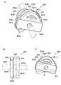
- the page turning roller which concerns on 2nd Embodiment is shown, (a) is a perspective view, (b) is a side view, (c) It is a top view. It is a page turning operation
- FIG. 1 is a configuration diagram of a booklet printer.
- a booklet printer 101 is equipped with a page turning unit 106 (booklet page turning device) according to an embodiment of the present invention.
- the page turning unit 106 is mounted on, for example, an automatic teller machine or a passbook bookkeeping apparatus, and prints a transaction history on the passbook.
- the booklet printer 101 includes an insertion slot 102 for inserting and ejecting a booklet, a conveyance unit 103 for conveying the booklet, a booklet reading unit 104 for reading a page code of the booklet, a printing mechanism unit 105 for printing on a booklet page, and a booklet page.
- a page turning unit 106 for turning pages, a control unit 107 for controlling these mechanism units, and the like are provided.
- the reading of the page code means reading of the magnetic stripe of the bankbook or reading of the barcode.
- the insertion slot 102 is provided on the front side of the housing of the booklet printer 101, and a sensor (not shown) for detecting that the booklet has been inserted is provided.
- a sensor (not shown) for detecting that the booklet has been inserted is provided.
- the booklet shown below is, for example, a binding of a plurality of paper sheets, and a hard (high rigidity) paper sheet is used for the front cover and the back cover, and soft between the cover and the back cover ( Paper sheets with low rigidity) are used.
- the conveyance unit 103 includes a lower conveyance guide 113 and an upper conveyance guide 114 that guide the booklet between the insertion slot 102 and the page turning unit 106.
- the transport unit 103 includes a plurality of transport rollers 115a to 115h that transport the booklet.
- the transport rollers 115a and 115b are disposed to face each other vertically, and the transport rollers 115c and 115d are disposed to face each other vertically.
- a booklet reading unit 104 is installed between the conveying rollers 115a and 115b and the conveying rollers 115c and 115d.
- the transport rollers 115e and 115f are disposed to face each other vertically, and the transport rollers 115g and 115h are disposed to face each other vertically.
- the printing mechanism 105 is installed between the conveying rollers 115e and 115f and the conveying rollers 115g and 115h.
- the transport rollers 115b, 115d, 115f, and 115h are drive rollers, and are configured such that the driven-side transport rollers 115a, 115c, 115e, and 115g are in pressure contact with the transport rollers 115b, 115d, 115f, and 115h. .
- FIG. 2 is a control block diagram of the booklet printer.
- the control unit 107 of the booklet printer 101 is connected to the main body control unit 201 via a bus 201a.
- the control unit 107 performs control according to a command from the main body control unit 201 and the state of the booklet printer 101.
- Inside the booklet printer 101 it is connected to drive systems and sensors of each unit (insertion slot 102, transport section 103, booklet reading section 104, print mechanism section 105, page turning section 106), and controls these drive systems. Yes.
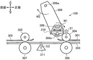
- FIG. 3 is a configuration diagram illustrating the booklet page turning apparatus according to the first embodiment.
- the page turning unit 106 includes a transport device (upper transport guides 301 and 302 and a lower transport guide 303 that form a booklet transport path, upper transport rollers 304 and 305, and a lower transport roller 306. 307), a page turning roller 308, a roller holding arm 309 for holding the page turning roller 308, and a push-up guide 311.
- the upper transport guides 301 and 302 are disposed above the booklet and are spaced apart in the front-rear direction (front side and rear side).
- the lower conveyance guide 303 is disposed below the booklet. A gap is formed between the upper conveyance guides 301 and 302 and the lower conveyance guide 303 so that the booklet can be conveyed.
- the upper transport roller 304 is disposed opposite to the lower transport roller 306 and is urged in a direction in which the booklet or the lower transport roller 306 is pressed by an elastic member such as a spring (not shown). Further, the upper conveying roller 304 is configured to be retractable upward (in the S1 direction) away from the booklet. A driving force of a motor (not shown) is transmitted to the lower conveyance roller 306, and the booklet is nipped and conveyed by the upper conveyance roller 304 and the lower conveyance roller 306.
- the upper transport roller 305 is disposed to face the lower transport roller 307 and is urged in a direction in which the booklet is pressed by an elastic member such as a spring (not shown).
- a driving force of a motor (not shown) is transmitted to the lower conveyance roller 307, and the booklet is nipped and conveyed by the upper conveyance roller 305 and the lower conveyance roller 307.
- the page turning roller 308 turns the page by pressing and rotating with respect to the turning page of the booklet, and is rotatably supported by the roller holding arm 309 via the shaft 308a. Further, the page turning roller 308 turns a booklet page by rotating once in the W1 direction by a driving force of a motor (not shown). The detailed shape of the page turning roller 308 will be described later.
- the roller holding arm 309 is rotatably supported by the casing of the page turning unit 106 via a shaft 309a. Further, the roller holding arm 309 is formed with a page holding protrusion 310 that catches the tip of the turned page when the page is turned.
- the shaft 309a of the roller holding arm 309 is located above the page turning roller 308, and the shaft 308a of the page turning roller 308 is located on the upper conveying roller 304 side than the shaft 309a.
- the roller holding arm 309 shown in FIG. 3 is in a state when turning the page in the forward direction.
- the roller holding arm 309 may be turned in the W2 direction via the shaft 309a so that the page can be turned in the reverse direction.
- the push-up guide 311 pushes up the booklet at the time of turning the page to make it easier to turn the page, and is arranged below the conveyance path.
- the push-up guide 311 is configured to move upward (in the direction S3) by a driving force of a motor (not shown).
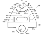
- FIG. 4 is a side view showing the page turning roller according to the first embodiment.
- FIG. 4 shows a state before the page turning roller 308 rotates (before turning the page), and the contact surface 620 faces upward.
- the page turning roller 308 includes a base portion 601 to which the shaft 308a is fixed, and an elastic portion 602 on which a contact surface 620 that contacts the booklet is formed.
- the base portion 601 is made of a highly rigid metal (such as an aluminum alloy) and has a holding portion 601a for holding the elastic portion 602 and a shaft hole 601b through which the shaft 308a is inserted.
- the elastic portion 602 is formed of an elastic material such as rubber and has a shape protruding from the base portion 601 in a substantially mountain shape. Further, the outer peripheral surface of the elastic portion 602 has slope portions 602a and 602b extending inward from both ends of the base portion 601, and a top portion 602c that connects these slope portions 602a and 602b.
- the top portion 602c has an arc shape centered on the point O of the shaft 308a.
- the elastic portion 602 has hollow portions 603 and 604 penetrating sideways (in the axial direction) (perpendicular to the paper surface of FIG. 4).
- the hollow portion 603 is located on the top portion 602c side of the elastic portion 602, and extends along the rotation direction W1 (left and right direction in FIG. 4) of the page turning roller 308, and both ends of the long hole portion 603a. And corner portions 603b and 603c having a triangular shape in a side view.
- the corner portion 603b protrudes toward a contact surface end portion P1 that is a boundary between the slope portion 602a and the top portion 602c.
- the corner portion 603c protrudes toward the contact surface end portion P2, which is the boundary between the slope portion 602b and the top portion 602c.
- the contact surface end portion P1 is an end of the rotation direction W1 of the page turning roller 308 that first comes into contact with the turning page of the contact surface 620 with the turning page when turning the page forward (see FIG. 3).
- the contact surface end portion P2 is an end portion in the direction opposite to the rotation direction W1 of the page turning roller 308 that first contacts the turning page, of the contact surface 620 with the turning page in the case of reverse turning.
- the thickness portions of the corner portions 603b and 603c and the contact surface end portions P1 and P2 are thinner than the thicknesses of the other portions. It is formed as.
- the thickness of the other part is the thickness of the part of the contact surface 620 excluding the contact surface end portions P1 and P2 (thin wall portions 609 and 610).
- the shape of the corner portions 603b and 603c is not limited to a triangular shape in a side view as long as the thin portions 609 and 610 are formed, and may be an arc shape or a curved shape.
- the hollow portion 604 is formed on the side of the base portion 601 opposite to the top portion 602c of the elastic portion 602 so as to be parallel to the hollow portion 603. Further, the hollow portion 604 is formed to have substantially the same length as the longitudinal direction of the hollow portion 603. In the present embodiment, the case where two hollow portions 603 and 604 are formed has been described as an example, but may be one, or may be three or more.
- the elastic portion 602 functions as a reinforcing bar 605 between the hollow portion 603 and the hollow portion 604.
- a concave portion 606 is formed in the central portion in the rotational direction W1 (the left-right direction in the drawing) at the top portion 602c of the elastic portion 602.
- the elastic portion 602 is formed with metal reinforcing portions 607 and 608 on both sides in the longitudinal direction of the hollow portion 604.
- the reinforcing portions 607 and 608 have a plate shape protruding from the base portion 601, and the ends of the reinforcing portions 607 and 608 extend to the position of the reinforcing bar 605.
- the reinforcing portion 607 is formed between one end of the hollow portion 604 in the longitudinal direction and the slope portion 602b (inside the page turning roller 308).
- the reinforcing portion 608 is formed between the other end in the longitudinal direction of the hollow portion 604 and the slope portion 602a. That is, the rubber portion of the elastic portion 602 is formed outside the reinforcing portions 607 and 608 (the left and right outside in the drawing).
- the page turning roller 308 is formed so as to be symmetric with respect to a virtual line VL connecting the concave portion 606 and the center O of the shaft 308a.
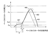
- FIG. 5 is a graph showing the pressing force of the page turning roller according to the first embodiment
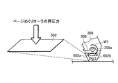
- FIG. 6 is an explanatory diagram regarding the pressing force of the page turning roller.
- a solid line 402 shown in FIG. 5 indicates a change in the pressing force of the page turning roller 308 in the present embodiment
- a broken line 401 shown in FIG. 5 indicates a change in the pressing force of the page turning roller in the conventional shape.
- the conventional shape is a simple shape in which one hollow portion is formed in an elastic portion having a curved shape in side view.
- the force required to buckle the booklet turning page (cover page turning sufficient value Fc, intermediate paper turning sufficient value Fp) is obtained.
- the front cover turning sufficient value Fc and the intermediate paper turning sufficient value Fp are values determined by the rigidity of the booklet paper (paper sheet) and are obtained by the following equations (1) and (2).
- Fc Rc / ( ⁇ r-1 ⁇ 1-2 ) (1)
- Fp Rp / ( ⁇ r-1 ⁇ 1-2 ) (2)
- Fp Cover sheet turning value
- Rc Cover buckling resistance
- the cover turning sufficient value Fc is equal to or greater than this value, under what environment (worst environment) This is a pressing force that can be applied even when a cover with a certain hardness is applied.
- the sufficient value for turning the intermediate paper Fp is a pressing force that can be turned even if the intermediate paper is turned in any environment (worst environment) as long as it is equal to or greater than this value.
- the upper limit value of the page turning roller 308 for not turning the second page (upper page turning upper limit value (before turning page buckling) Fp2, the upper limit value for turning the two sheets). (After flipping page buckling) F'p2) exists.
- the two-sheet turning upper limit values Fp2 and F′p2 are obtained by the following formulas (3) and (4), in which there are two cases of static frictional force and dynamic frictional force before and after the turning page buckles and starts moving.
- Fp2 Rp / ( ⁇ 1-2 - ⁇ 2-3 ) (3)
- F′p2 Rp / ( ⁇ ′ 1-2 ⁇ 2-3 ) (4)
- F'p2 Upper limit value for turning two sheets in the dynamic friction coefficient
- ⁇ 2-3 Static friction coefficient between the second and third pages
- ⁇ ' 1-2 Turning page Coefficient of friction between the first page and the second page
- the pressing force indicated by the solid line 402 in FIG. 5 is a vertical force (page) applied from the page turning roller 308 to the contact surface 502 when the page turning roller 308 is rotated in the rotation direction W1 in the figure. It is obtained by measuring the pressing force of the turning roller 308.
- the pressing force increases with the rotation of the page turning roller, and is set so as to reach a peak at a point facing approximately right below.
- Fc cover cover sufficient value
- the page turning roller has a steep rising pressing force for that purpose, the angle range A (see FIG. 5) of the pressing force that does not turn two sheets when turning the middle sheet (less than the two-sheet turning upper limit Fp2) becomes narrower. It becomes easier to turn two sheets by applying a pressing force more than necessary (Fp2 or more) before the page is buckled.
- a page turning roller having a weak pressing force is used to prevent turning two sheets when turning the middle sheet, the peak value of the pressing force of the page turning roller becomes small, and non-picking becomes easier when turning the cover.
- the page turning roller 308 of the first embodiment generates a two-step step-like pressing force. That is, a gentle pressing force is generated at the beginning of turning, and the pressing force increases as the rotation of the page turning roller 308 advances, so that a large pressing force can be generated.
- the page turning roller buckles and starts to move by the gentle pressing force at the beginning of turning (first step 407, first pressing force), so that the conventional page turning roller can be moved.
- the angle range B (see FIG. 5) of the pressing force that does not turn two sheets (the intermediate sheet turning sufficient value Fp or more and less than the two-sheet turning upper limit value Fp2) is increased.
- the pressing force becomes a two-step staircase, so that the cover sheet non-pick prevention performance and the middle sheet two page turn prevention performance are achieved. Will improve.
- FIG. 7 is a page turning operation diagram of the booklet page turning apparatus according to the first embodiment.
- FIG. 7 shows the operation when turning the middle paper
- FIG. 7 (a) is before the page turning operation
- (b) is when the page is flipped
- (c) is when the page is turned up
- (d) is the page turning.
- (e) shows the time of booklet conveyance.
- the roller holding arm 309 is held in a tilted state toward the booklet conveyance side, and the page turning roller 308 is set upward (in a state where the rotation angle is 0 degree). Further, the push-up guide 311 is retracted below the lower conveyance guide 303.
- FIGS. 4 and 5 description will be made with reference to FIGS. 4 and 5 as appropriate.
- a booklet 701 inserted from the insertion slot 102 is transported by transport rollers 115a to 115g (see FIG. 1) of the transport unit 103, and the upper transport rollers 304 and 305 of the page turning unit 106 and It is transported by the lower transport rollers 306 and 307, transported to a predetermined position shown in FIG.
- the predetermined position means that the front end of the booklet (the side opposite to the binding margin) can be sandwiched between the upper conveying roller 304 and the lower conveying roller 306, and the binding margin side of the booklet is the upper conveying roller 305 and the lower conveying roller. This position can be sandwiched between 307 and 307.
- the upper conveying roller 304 located on the opening side of the booklet 701 is retracted in the direction of the arrow S1 so as not to obstruct the page turning.
- the page turning roller 308 is rotated in the W1 direction (clockwise direction in the drawing), and the push-up guide 311 is operated in the arrow S2 direction.
- the push-up guide 311 is raised when the page turning roller 308 is at an angle before coming into contact with the turning page of the booklet 701.
- the push-up guide 311 the turning page can be easily buckled.
- the page turning roller 308 presses and turns the page to be turned of the booklet 701, so that the page turning is buckled.
- the space of the corner portion 603b of the page turning roller 308 expands (extends) in the S10 direction (see FIG. 4) and the corner.
- the space of the portion 603c narrows (shrinks) in the direction of the arrow S20, the pressing force on the booklet can be kept low.
- the pressing force of the page turning roller 308 gradually increases, and it is possible to secure a long time until it exceeds the upper limit value Fp2 for turning two sheets (before turning page buckling). (See FIG. 5).
- the angle range B is wide. (Too large) can be prevented.
- the concave portion 606 in the page turning roller 308 it is possible to contribute to the deformation of the corner portion 603b when the thin-walled portion 609 is deformed (because it is easily deformed), so the pressing shown in the first step 407 in FIG. The pressure can be kept low.
- the space of the corner portion 603b expands in the S10 direction and the space of the corner portion 603c closes in the S20 direction, so that the elastic portion 602 is stretched (is difficult to deform), and the pressing force of the page turning roller 308 is reduced. It can be increased rapidly.
- the reinforcing portion 607 on the side opposite to the rotation direction W1 of the thin portion 609 (contact surface end portion P1), further collapse of the elastic portion 602 can be suppressed (preventing excessive deformation of rubber). Therefore, the pressing force of the page turning roller 308 can be increased rapidly.
- the elastic portion 602 is more than in the case where the reinforcing portion 607 is on the outermost side of the elastic portion 602. Can be released to the outside (in the direction of arrow S30), and the pressing force of the page turning roller 308 can be prevented from being excessively increased (exceeding the upper limit value of two pages (after page turning buckling) F′p2).
- the page turning roller 308 is further rotated to rotate about 180 degrees (180 ⁇ 15 degrees) (when the page turning roller 308 is in the downward state), the page turning roller The pressing force of 308 becomes a peak value (second step 408). Since the peak value of the pressing force is set to be less than the upper limit value (after page turning buckling) F′p2 for turning two sheets, two sheets are turned even after the turning page of the middle sheet is buckled. There is nothing to do.
- the push-up guide 311 is retracted in the direction of the arrow S3, and the page turning roller 308 is continuously rotated in the direction of the arrow W1, so that the middle paper turning page is lifted in a buckled state. It is done. Note that the timing for operating the push-up guide 311 is in the middle of the page turning roller 308 being in contact with the intermediate paper.
- the page turning roller 308 is continuously rotated until it rotates once, thereby turning up the turning page of the intermediate paper and hooking the turning page on the page holding protrusion 310 of the roller holding arm 309. Hold. Then, the upper conveyance roller 304 is moved again in the direction of the arrow S 4, and the pull-in booklet 701 other than the turning pages is sandwiched between the upper conveyance roller 304 and the lower conveyance roller 306.
- the booklet 701 is transported in the direction of arrow S5 by the upper transport rollers 304 and 305 and the lower transport rollers 306 and 307, so that the turning page is detached from the page holding protrusion 310.
- the turning page is turned, and the page turning operation is completed.
- the page turning roller 308 is rotated once so that the cover is turned.
- the case of turning the cover is, for example, turning a closed new passbook in the machine (page turning unit 106) when issuing a new passbook.
- the page turning rollers 308 are formed symmetrically in FIG. 4, so that page turning in the reverse direction (hereinafter referred to as “reverse turning”) is possible. Yes.
- the case of turning over is, for example, when closing an open page or returning a page.
- the roller holding arm 309 is rotated (swinged) in the W2 direction (see FIG. 3), and the page turning roller 308 is rotated in the direction opposite to the W1 direction.
- the upper transport roller 305 is configured to be retractable in a direction away from the booklet.
- the elastic portion 602 is stretched (is difficult to be deformed), and the pressing force of the page turning roller 308 can be increased rapidly.
- the reinforcing portion 608 on the opposite side to the rotation direction of the thin-walled portion 610 (contact surface end portion P2), further collapse of the elastic portion 602 can be suppressed (preventing excessive deformation of rubber).
- the pressing force of the page turning roller 308 can be increased rapidly.
- a transport device that transports the booklet 701 (upper transport guides 301 and 302, lower transport guide 303, upper transport rollers 304 and 305, and lower transport rollers 306 and 307);
- two or more levels of pressing force see FIG. The first stage 407 and the second stage 408).
- a two-stage pressing force can be generated only by rotating the page turning roller 308, and it can be configured by only one mechanism for rotating the page turning roller 308. Therefore, it is possible to perform page turning of booklets having pages with different rigidity without providing an additional mechanism such as a mechanism for cooling and heating the page turning roller 308 or a mechanism for moving an arm for holding the page turning roller as in the past. It becomes possible.
- hollow portions 603 and 604 are formed inside the page turning roller 308, and the page turning roller 308 has the contact surface end portions P1 and P2 of the contact surface 620 with the turning page.
- Thin portions 609 and 610 whose thickness is thinner than the thickness of other portions are formed (see FIG. 4). According to this, when the contact surface end portions P1 and P2 hit the turning page, the thin wall portions 609 and 610 can secure a large angle range B corresponding to the pressing force of the first step 407, so It is possible to generate a large pressing force, and it is possible to prevent the turning of the two middle sheets.
- the page turning roller 308 is provided with reinforcing portions 607 and 608 on the opposite side of the contact surface end portions P1 and P2 and the rotation direction W1 (see FIG. 4). According to this, since the further turning of the page turning roller 308 (elastic portion 602) can be suppressed, the pressing force of the page turning roller 308 can be increased rapidly.
- the reinforcing portions 607 and 608 are located inside the page turning roller 308 (see FIG. 4). According to this, the rubber part (elastic deformation) of the elastic part 602 can be released to the outside (in the direction of the arrow S30), compared to the case where the reinforcing parts 607 and 608 are on the outermost side of the page turning roller 308 (elastic part 602). Therefore, it is possible to prevent the pressing force of the page turning roller 308 from excessively increasing (exceeding the upper limit value of two sheets (after turning page buckling) F′p2).
- the page turning roller 308 is formed with a recess 606 at the center of the contact surface 620 in the rotation direction W1 (see FIG. 4). According to this, when the thin-walled portions 609 and 610 are elastically deformed, they can contribute to the elastic deformation, so that the pressing force indicated by the first stage 407 in FIG. 5 can be kept low.
- the page turning roller 308 is formed with a reinforcing bar 605 that is divided into a hollow portion 603 of the contact surface 620 and a hollow portion 604 on the center O side (rotating shaft side) of the shaft 308a ( (See FIG. 4). According to this, the angle range B of the gentle pressing force at the beginning of turning can be adjusted so as not to become too large, and the pressing force can be increased at an appropriate angle.
- the page turning roller 308 is formed symmetrically with respect to an imaginary line VL passing through the center portion (concave portion 606) of the contact surface 620 and the center O (see FIG. 4). According to this, not only page turning in one direction but also page turning in the reverse direction is possible.
- the upper transport roller 304 is retracted from the booklet 701, the booklet 701 is pushed up from below by the push-up guide 311, and the page turning roller 308 is rotated. It is configured to turn. According to this, the turning page can be easily buckled.
- FIG. 8 shows a page turning roller according to the second embodiment, wherein (a) is a perspective view, (b) is a side view, and (c) is a plan view.
- the booklet page turning apparatus (page turning unit 106) of the second embodiment differs from the first embodiment in the shape of the page turning roller, and uses a page turning roller 800 instead of the page turning roller 308.
- the booklet page turning apparatus and operation in the present embodiment are the same as those in the first embodiment.
- the page turning roller 800 has a shape in which three rollers 801, 802, and 803 are integrated.
- the rollers 801 and 803 both have the same shape and characteristics, and are made of soft rubber that generates a pressing force for the intermediate paper.
- the roller 802 is made of hard rubber that generates a pressing force for the cover. Note that the roller 803 corresponds to the reverse turning of the page as in the first embodiment.
- the rollers 801 and 803 include base portions 801a and 803a to which the shaft 308a is fixed, and elastic portions 801b and 803b that come into contact with the booklet.
- the roller 802 includes a base portion 802a and an elastic portion 802b.
- the base portions 801a, 802a, and 803a are made of, for example, metal.
- the elastic portions 801b, 802b, and 803b are substantially mountain-shaped (substantially triangular) in a side view, and hollow portions 801c, 802c, and 803c penetrating in the axial direction are formed inside the elastic portions 801b, 802b, and 803b. Has been.
- the roller 801 is fixed in a state where it is rotated with respect to the roller 802 in one rotation direction of the shaft 308a.
- the roller 803 is fixed in a state where it is rotated in the other rotational direction of the shaft 308a with respect to the roller 802 (configured in a state where the phases of the three rollers 801, 802 and 803 are shifted).
- the contact surface 801d at the top of the roller 801 is arranged to be offset in the rotational direction of the shaft 308a with respect to the contact surface 802d at the top of the roller 802.
- the contact surface 803d at the top of the roller 803 is disposed offset with respect to the contact surface 802d in the direction of rotation opposite to that of the shaft 308a.
- the contact surface 801d of the roller 801 has an arc shape centered on the point O of the shaft 308a.
- the contact surface 802d of the roller 802 has an arc shape centered on the point O
- the contact surface 803d of the roller 803 has an arc shape centered on the point O.
- the contact surfaces 801d, 802d, and 803d have an arc shape having the same diameter with the point O as the center.
- the pressing force when turning the page is the same as that in the first embodiment (the first stage 407 and the second stage shown in FIG. 5). Stage 408) The existing effects can be obtained.
- FIG. 9 is a page turning operation diagram of the booklet page turning apparatus according to the second embodiment. 9 (a), (c), (d), and (e) are the same as FIGS. 7 (a), (c), (d), and (e). Only b) will be described.
- the page turning roller 800 is rotated in the W1 direction (clockwise direction in the drawing) and pressed against the booklet 701.
- the roller 801 of the page turning roller 800 first hits the booklet 701
- a pressing force corresponding to the turning of the intermediate paper can be generated.
- the contact surface 801d of the roller 801 is formed long in the W1 direction of the page turning roller 800, the pressing force of the page turning roller 800 gradually increases as shown in the first step 407 in FIG. It is possible to prevent turning two sheets.
- the contact surface 801d of the roller 801 first presses against the cover, but here, since only the pressing force corresponding to the turning of the inner sheet is generated, the cover is buckled and turned. Absent. Then, the page turning roller 800 further rotates in the W1 direction, and the contact surface 802d (see FIG. 8A) of the roller 802 presses against the cover, so that the pressing force increases rapidly, corresponding to the cover turning. Can be generated.
- the roller holding arm 309 is rotated (swinged) in the W2 direction (see FIG. 3), and the page turning roller 800 is rotated in the reverse direction to the W1 direction. Can be done.
- the page turning roller 800 is rotated, and the contact surface 803d of the roller 803 first presses the middle paper, so that the middle paper can be turned over.
- the cover surface can be turned upside down by the contact surface 802d of the roller 802 pressing the cover after the contact surface 803d of the roller 803 presses the cover.
- the second embodiment configured as described above includes a transport device that transports the booklet 701, and a page turning roller 800 that turns and presses the booklet 701 to turn the page of the booklet 701.
- 800 has a shape that generates a pressing force of two or more levels (the first level 407 and the second level 408 in FIG. 5) when turning the page of the booklet 701. According to this, it is possible to generate a two-stage pressing force only by rotating the page turning roller 800, and it is possible to configure with only one mechanism for rotating the page turning roller 800. Therefore, it is possible to perform page turning of booklets having pages with different rigidity without providing an additional mechanism such as a mechanism for cooling and heating the page turning roller 308 or a mechanism for moving an arm for holding the page turning roller as in the past. It becomes possible.
- the scope of the present invention is not limited to these, and various modifications can be made within the scope described in the claims.
- the two-step step-like page turning rollers 308 and 800 are used. However, depending on the booklet to be handled, if there are some appropriate pressing forces, a page turning roller having a larger number of steps is used. By using it, it becomes possible to prevent the occurrence of turning of two sheets and non-picking of a turning page.
- the angle range of the pressing force that does not turn two pages during page turning is increased by the pressing force characteristics of the page turning rollers 308 and 800, but by reducing the page turning speed at the beginning of turning, 2
- An effect similar to that of the present invention can also be obtained by increasing the time existing at the angle of the pressing force that does not turn the sheets.
Landscapes
- Handling Of Cut Paper (AREA)
Abstract
ページめくりローラ(308)は、当該ページめくりローラ(308)の内部に中空部(603,604)を有し、冊子のめくりページとの接触面(620)のうち、めくりページと始めに接触する当該ページめくりローラ(308)の回転方向(W1)の接触面端部(P1,P2)の肉厚が接触面(620)の他の部分の肉厚よりも薄い薄肉部(609,610)を有する。
Description
本発明は、通帳等の冊子を取り扱う冊子取扱装置において、冊子のページをめくる冊子ページめくり装置および冊子ページめくり方法に関する。
通帳等に印刷することができる冊子プリンタには自動的にページをめくる機構であるページめくり装置が備わっているものがある。このページめくり装置は、現在印刷中のページの記帳が終了すると、自動的に次ページのページめくりを行うものである。一般的なページめくり装置では、搬送路上に停止した冊子を、ページめくりローラの押圧回転によって冊子綴じ側に押し込み、めくりページを座屈させて持ち上げる。その後、めくったページを持ち上げた状態で残った冊子を押し込み側とは反対方向へ搬送することでページをめくる。しかしながら,このようなページめくり装置では、めくり対象のページに加わる垂直力であるページめくりローラの押圧力の過不足によって、ページの2枚めくりやノンピックといった問題が生じる。
特に、通帳のような冊子は、表紙と中紙とで紙の剛性等といった性質が大きく異なる。一般に表紙は剛性が高く、中紙は剛性が低い。そのため、表紙をめくるために高い押圧力を発生させることのできるページめくりローラを使用すると、中紙をめくる際に2枚めくりが発生しやすくなる。また、中紙をめくる際の2枚めくりを防ぐために、低い押圧力のページめくりローラを使用すると、表紙めくりの際にノンピックの問題が発生しやすくなる。
このような問題の対策として、特許文献1に記載のページめくり装置では、ゴムローラを冷加温(冷却および加熱)することによってゴムローラの硬度を変化させ、ページめくりする際のゴムローラの押圧力を制御してページめくりを実現している。また、特許文献2に記載のページめくり装置では、ページめくりローラの回転と連動するアームを設け、そのアームの回転によりページめくりローラの押圧力を制御してページめくりを実現している。
しかしながら、特許文献1に記載のページめくり装置では、ページめくりローラの硬度を変化させるための冷加温手段を備える必要があり、さらに温度制御のためのセンサも必要になるため、装置が複雑になる問題がある。また、特許文献2に記載のページめくり装置では、ページめくりする際の押圧力を制御するために、めくりローラを回転させるモータの他に、アームを可動させるためのモータが必要になり、装置が複雑になる問題がある。これらのページめくり装置では、いずれもページめくりローラの押圧力を制御するために追加の機構を必要としており、その結果として装置が複雑化するものであった。
本発明は、前記した従来の問題を解決するものであり、追加の機構を設けることなく剛性の異なるページを有する冊子のページめくりを行うことが可能な冊子ページめくり装置および冊子ページめくり方法を提供することを目的とする。
本発明は、冊子を搬送する搬送装置と、前記冊子に対して押圧回転することで当該冊子のページをめくるページめくりローラと、を備え、前記ページめくりローラは、前記冊子のページをめくっている際、少なくとも2段以上の押圧力を発生させる形状を有することを特徴とする。
本発明によれば、追加の機構を設けることなく剛性の異なるページを有する冊子のページめくりを行うことが可能な冊子ページめくり装置および冊子ページめくり方法を提供できる。
以下、本発明を実施するための形態(以下「実施形態」という)について、適宜図面を参照しながら詳細に説明する。
(第1実施形態)
図1は、冊子プリンタの構成図である。
図1に示すように、冊子プリンタ101には、本発明の実施形態に係るページめくり部106(冊子ページめくり装置)が搭載されている。このページめくり部106は、例えば、現金自動取引装置や通帳の記帳装置に搭載され、通帳に取引の履歴を印字するものである。
(第1実施形態)
図1は、冊子プリンタの構成図である。
図1に示すように、冊子プリンタ101には、本発明の実施形態に係るページめくり部106(冊子ページめくり装置)が搭載されている。このページめくり部106は、例えば、現金自動取引装置や通帳の記帳装置に搭載され、通帳に取引の履歴を印字するものである。
また、冊子プリンタ101は、冊子を挿入および排出する挿入口102、冊子を搬送する搬送部103、冊子のページコードを読み取る冊子読取部104、冊子のページに印字する印字機構部105、冊子のページめくりを行うページめくり部106、これらの機構部の制御を行う制御部107などを備えて構成されている。なお、ページコードの読み取りとは、通帳のマグネットストライプの読み取りやバーコードの読み取りである。
挿入口102は、冊子プリンタ101の筺体の正面側に設けられ、冊子が投入されたことを検知するセンサ(不図示)が設けられている。なお、以下に示す冊子は、例えば、複数枚の紙葉類を綴じたものであり、表紙および裏表紙に硬い(剛性の高い)紙葉が用いられ、表紙と裏表紙との間に柔らかい(剛性の低い)紙葉が用いられたものである。
搬送部103は、挿入口102とページめくり部106との間で冊子をガイドする下側搬送用ガイド113と上側搬送用ガイド114とを備えている。また、搬送部103は、冊子を搬送させる複数の搬送用ローラ115a~115hを備えている。
搬送用ローラ115a,115bは、上下に対向して配置され、搬送用ローラ115c,115dは、上下に対向して配置されている。搬送用ローラ115a,115bと搬送用ローラ115c,115dとの間に冊子読取部104が設置されている。
搬送用ローラ115e,115fは、上下に対向して配置され、搬送用ローラ115g,115hは、上下に対向して配置されている。搬送用ローラ115e,115fと搬送用ローラ115g,115hとの間に印字機構部105が設置されている。
搬送用ローラ115b,115d,115f,115hは、駆動ローラであり、従動側の搬送用ローラ115a,115c,115e,115gが搬送用ローラ115b,115d,115f,115hに圧接するように構成されている。
図2は、冊子プリンタの制御ブロック図である。
図2に示すように、冊子プリンタ101の制御部107は、バス201aを介して本体制御部201と接続されている。制御部107は、本体制御部201からの指令および冊子プリンタ101の状態に応じて制御を行っている。冊子プリンタ101の内部では、各ユニット(挿入口102、搬送部103、冊子読取部104、印字機構部105、ページめくり部106)の駆動系統やセンサと接続され、それら駆動系の制御を行っている。
図2に示すように、冊子プリンタ101の制御部107は、バス201aを介して本体制御部201と接続されている。制御部107は、本体制御部201からの指令および冊子プリンタ101の状態に応じて制御を行っている。冊子プリンタ101の内部では、各ユニット(挿入口102、搬送部103、冊子読取部104、印字機構部105、ページめくり部106)の駆動系統やセンサと接続され、それら駆動系の制御を行っている。
図3は、第1実施形態の冊子ページめくり装置を示す構成図である。
図3に示すように、ページめくり部106は、搬送装置(冊子の搬送路を構成する上側搬送ガイド301,302および下側搬送ガイド303と、上側搬送ローラ304,305と、下側搬送ローラ306,307)と、ページめくりローラ308と、ページめくりローラ308を保持するローラ保持アーム309と、押し上げガイド311と、を備えて構成されている。
図3に示すように、ページめくり部106は、搬送装置(冊子の搬送路を構成する上側搬送ガイド301,302および下側搬送ガイド303と、上側搬送ローラ304,305と、下側搬送ローラ306,307)と、ページめくりローラ308と、ページめくりローラ308を保持するローラ保持アーム309と、押し上げガイド311と、を備えて構成されている。
上側搬送ガイド301,302は、冊子の上方に配置され、前後方向(正面⇔背面)に離間して配置されている。下側搬送ガイド303は、冊子の下方に配置されている。上側搬送ガイド301,302と下側搬送ガイド303との間には、冊子を搬送可能とする隙間が形成されている。
上側搬送ローラ304は、下側搬送ローラ306と対向して配置され、ばね(不図示)などの弾性部材によって冊子または下側搬送ローラ306を圧接する方向に付勢されている。また、上側搬送ローラ304は、冊子から離れる上方(S1方向)に向けて退避可能に構成されている。下側搬送ローラ306には、モータ(不図示)の駆動力が伝達され、上側搬送ローラ304と下側搬送ローラ306とで冊子を挟持して搬送する。
上側搬送ローラ305は、下側搬送ローラ307と対向して配置され、ばね(不図示)などの弾性部材によって冊子を圧接する方向に付勢されている。下側搬送ローラ307には、モータ(不図示)の駆動力が伝達され、上側搬送ローラ305と下側搬送ローラ307とで冊子を挟持して搬送する。
ページめくりローラ308は、冊子のめくりページに対して押圧回転することでページめくりするものであり、ローラ保持アーム309に軸308aを介して回転自在に支持されている。また、ページめくりローラ308は、モータ(不図示)の駆動力によってW1方向に1回転することにより、冊子のページめくりを行う。なお、ページめくりローラ308の詳細な形状については後記する。
ローラ保持アーム309は、ページめくり部106の筺体に軸309aを介して回動自在に支持されている。また、ローラ保持アーム309には、ページがめくられたときに、めくりページの先端が引っ掛かるページ保持突起310が形成されている。
また、ローラ保持アーム309の軸309aは、ページめくりローラ308の上方に位置するとともに、ページめくりローラ308の軸308aが軸309aよりも上側搬送ローラ304側に位置している。図3に示すローラ保持アーム309は、ページを順方向にめくるときの状態である。なお、ローラ保持アーム309を、軸309aを介してW2方向に回動させることで、ページを逆方向にもめくることができるようにしてもよい。
押し上げガイド311は、ページめくり時に冊子を押し上げて、ページをめくり易くするものであり、搬送路の下方に配置されている。また、押し上げガイド311は、モータ(不図示)の駆動力によって上方(S3方向)に可動するように構成されている。
図4は、第1実施形態に係るページめくりローラを示す側面図である。なお、図4は、ページめくりローラ308が回転する前(ページめくりする前)の状態であり、接触面620が上向きとなっている。
図4に示すように、ページめくりローラ308は、軸308aが固定されるベース部601と、冊子と接触する接触面620が形成される弾性部602とを備えて構成されている。
図4に示すように、ページめくりローラ308は、軸308aが固定されるベース部601と、冊子と接触する接触面620が形成される弾性部602とを備えて構成されている。
ベース部601は、剛性の高い金属製のもの(アルミニウム合金など)で構成され、弾性部602を保持する保持部601aと、軸308aが挿通される軸孔601bと、を有している。
弾性部602は、ゴムなどの弾性材料で形成され、ベース部601から略山型に突出する形状を有している。また、弾性部602の外周面は、ベース部601の両端から互いに内向きに延びる斜面部602a,602bと、こられの斜面部602a,602b同士をつなぐ頂部602cと、を有している。頂部602cは、軸308aの点Oを中心とした円弧形状を呈している。このように、頂部602cを円弧形状とすることにより、頂部602cが冊子と接したときに弾性部602が変形することで頂部602cを平面の状態で冊子に押し当てることができる。
また、弾性部602は、側方(軸方向)に向けて(図4の紙面に対して垂直方向に)貫通する中空部603,604を有している。
中空部603は、弾性部602の頂部602c側に位置し、ページめくりローラ308の回転方向W1(図4の左右方向)に沿って延在する長孔部603aと、この長孔部603aの両端部において側面視三角形状を呈する角部603b,603cと、を有して構成されている。
角部603bは、斜面部602aと頂部602cとの境界である接触面端部P1に向けて突出している。角部603cは、斜面部602bと頂部602cとの境界である接触面端部P2に向けて突出している。なお、接触面端部P1は、ページを順めくりする場合(図3参照)において、めくりページとの接触面620のうち、めくりページと始めに接触する当該ページめくりローラ308の回転方向W1の端部である。また、接触面端部P2は、逆めくりする場合において、めくりページとの接触面620のうち、めくりページと始めに接触する当該ページめくりローラ308の回転方向W1と逆方向の端部である。
前記した形状の中空部603を設けることにより、弾性部602において、角部603b,603cと接触面端部P1,P2との肉厚が、他の部分の肉厚よりも薄い薄肉部609,610として形成されている。なお、他の部分の肉厚とは、接触面620のうちの接触面端部P1,P2(薄肉部609,610)を除く部分の肉厚である。また、角部603b,603cの形状は、薄肉部609,610が形成されるものであれば、側面視三角形状に限定されるものではなく、円弧形状や湾曲形状であってもよい。
中空部604は、弾性部602の頂部602cとは逆のベース部601側に、中空部603と平行となるように形成されている。また、中空部604は、中空部603の長手方向と略同じ長さで形成されている。なお、本実施形態では、2つの中空部603,604が形成された場合を例に挙げて説明したが、1つであってもよく、3つ以上であってもよい。
また、弾性部602は、中空部603と中空部604との間が、補強桟605として機能している。
また、弾性部602の頂部602cには、回転方向W1(図示左右方向)の中央部に、凹部606が形成されている。
また、弾性部602には、中空部604の長手方向の両側に金属製の補強部607,608が形成されている。この補強部607,608は、ベース部601から突出する板形状であり、補強部607,608の先端が、補強桟605の位置まで延びている。
補強部607は、中空部604の長手方向の一端と斜面部602bとの間(ページめくりローラ308の内部)に形成されている。補強部608は、中空部604の長手方向の他端と斜面部602aとの間に形成されている。つまり、補強部607,608の外側(図示左右外側)に弾性部602のゴム部分が形成されるように構成されている。
また、ページめくりローラ308は、凹部606と軸308aの中心Oとを結ぶ仮想線VLに対して線対称となるように形成されている。
図5は、第1実施形態に係るページめくりローラの押圧力を示すグラフ、図6は、ページめくりローラの押圧力に関する説明図である。なお、図5に示す実線402は、本実施形態におけるページめくりローラ308の押圧力の変化を示し、図5に示す破線401は、従来形状におけるページめくりローラの押圧力の変化を示している。従来形状とは、側面視湾曲形状の弾性部に1つの中空部が形成された単純形状のものである。
図5に示すように、ページめくり部106において冊子のページめくりを行う際には、冊子のめくりページを座屈させるために必要な力(表紙めくり十分値Fc、中紙めくり十分値Fp)が存在する。この表紙めくり十分値Fcおよび中紙めくり十分値Fpは、冊子の紙(紙葉)の剛性により決定される値であり、以下の式(1)、(2)によって求められる。
Fc=Rc/(μr-1-μ1-2)・・・(1)
Fp=Rp/(μr-1-μ1-2)・・・(2)
Fc:表紙めくり十分値
Fp:中紙めくり十分値
Rc:表紙の座屈抵抗力
Rp:中紙の座屈抵抗力
μr-1:ページめくりローラとめくりページ間の摩擦係数
μ1-2:めくりページ2枚目ページ間の静止摩擦係数
Fc=Rc/(μr-1-μ1-2)・・・(1)
Fp=Rp/(μr-1-μ1-2)・・・(2)
Fc:表紙めくり十分値
Fp:中紙めくり十分値
Rc:表紙の座屈抵抗力
Rp:中紙の座屈抵抗力
μr-1:ページめくりローラとめくりページ間の摩擦係数
μ1-2:めくりページ2枚目ページ間の静止摩擦係数
なお、冊子によっても硬さが違い、環境によっても硬さが変わるので、ここでの表紙めくり十分値Fcは、この値以上であれば、どのような環境(最悪な環境)下で、どのような硬さの表紙がきてもめくれる押圧力である。また、中紙めくり十分値Fpについても、この値以上であれば、どのような環境(最悪な環境)下で、どのような硬さの中紙がきてもめくれる押圧力である。
また、冊子のうちの中紙のページめくりを行う際には、2枚めくりしないためのページめくりローラ308の上限値(2枚めくり上限値(めくりページ座屈前)Fp2,2枚めくり上限値(めくりページ座屈後)F'p2)が存在する。この2枚めくり上限値Fp2,F'p2は、めくりページが座屈し、動き出す前後によって静止摩擦力と動摩擦力の2つの場合が存在し、以下の式(3)、(4)によって求められる。
Fp2=Rp/(μ1-2-μ2-3)・・・(3)
F'p2=Rp/(μ'1-2-μ2-3)・・・(4)
Fp2:静止摩擦係数における2枚めくり上限値
F'p2:動摩擦係数における2枚めくり上限値
μ2-3:2枚目ページと3枚目ページ間の静止摩擦係数
μ'1-2:めくりページと2枚目ページ間の動摩擦係数
Fp2=Rp/(μ1-2-μ2-3)・・・(3)
F'p2=Rp/(μ'1-2-μ2-3)・・・(4)
Fp2:静止摩擦係数における2枚めくり上限値
F'p2:動摩擦係数における2枚めくり上限値
μ2-3:2枚目ページと3枚目ページ間の静止摩擦係数
μ'1-2:めくりページと2枚目ページ間の動摩擦係数
図6に示すように、図5の実線402で示す押圧力は、ページめくりローラ308を図中の回転方向W1に回転させる際、ページめくりローラ308から接触面502に加わる垂直方向の力(ページめくりローラ308の押圧力)を測定することで得られるものである。
ところで、図5に示すように、破線401で示す従来のページめくりローラでは、ページめくりローラの回転とともに押圧力が増大し、おおよそ真下を向いた地点でピークを迎えるように設定されている。表紙のノンピック(めくり上げ失敗)を起こさせないためには、少なくともこのピーク地点で表紙めくり十分値Fcを超える必要がある。しかし、そのために急峻な立ち上がりの押圧力をもつページめくりローラにすると、中紙めくり時に2枚めくりしない押圧力(2枚めくり上限値Fp2未満)の角度範囲A(図5参照)が狭くなり、めくりページが座屈する前に必要以上(Fp2以上)の押圧力が加わることで2枚めくりしやすくなってしまう。また、中紙めくり時に2枚めくりを防ごうと、押圧力の弱いページめくりローラを用いると、ページめくりローラの押圧力のピーク値が小さくなってしまい、表紙めくり時にノンピックしやすくなってしまう。
図5に示すように、第1実施形態のページめくりローラ308では、2段の階段状の押圧力が発生するようになっている。すなわち、めくり始めの部分では、緩やかな押圧力を生み出し、ページめくりローラ308の回転が進むと押圧力が増大し、大きな押圧力を生み出すことができる。
さらに説明すると、中紙めくり時は、めくり始めの緩やかな押圧力(最初の段407、第1の押圧力)によって、めくりページを座屈させて動き出させることで、従来のページめくりローラに比べて、2枚めくりしない押圧力(中紙めくり十分値Fp以上2枚めくり上限値Fp2未満)の角度範囲B(図5参照)を大きくしている。これにより、めくりページが座屈する前に必要以上の押圧力が加わるのを防ぐことができ、2枚めくり防止性能を向上させることが可能となる。また、ページめくりローラ308の回転が進んだ後の増大した押圧力(2つ目の段408、第2の押圧力)が存在することで、表紙めくり時のノンピックを防ぐことができる。
このように、ページめくりローラ308の押圧力の増加量がページめくりの最中に変化することによって、押圧力が2段の階段状となり、表紙ノンピックの防止性能および中紙2枚めくりの防止性能が向上する。
図7は、第1実施形態に係る冊子ページめくり装置のページめくり動作図である。図7は、中紙めくり時の動作を示し、図7(a)はページめくり動作前、(b)はめくりページ座屈時、(c)はページめくり上げ時、(d)はめくりページ引掛け時、(e)は冊子搬送時を示している。ページめくり動作開始前においては、ローラ保持アーム309が冊子搬送側に傾いた状態で保持されるとともに、ページめくりローラ308が上向き(回転角度0度の状態)に設定されている。また、押し上げガイド311が下側搬送ガイド303の下方に退避している。なお、以下では、図4および図5を適宜参照して説明する。
まず、挿入口102(図1参照)から挿入された冊子701を、搬送部103の搬送用ローラ115a~115g(図1参照)によって搬送し、さらにページめくり部106の上側搬送ローラ304,305および下側搬送ローラ306,307によって搬送し、図7(a)に示す所定位置に搬送して停止させる。なお、所定位置とは、冊子の先端(綴じ代と反対側)を上側搬送ローラ304と下側搬送ローラ306とで挟み込むことができ、冊子の綴じ代側を上側搬送ローラ305と下側搬送ローラ307とで挟み込むことができる位置である。そして、ページめくりの際に邪魔にならないよう、冊子701の開き側に位置する上側搬送ローラ304を矢印S1方向へ退避させる。
そして、図7(b)に示すように、ページめくりローラ308をW1方向(図示時計回り方向)に回転させるとともに、押し上げガイド311を矢印S2方向に動作させる。具体的には、例えば、ページめくりローラ308が冊子701のめくりページに接触する前のある角度になったときに押し上げガイド311を上昇させる。押し上げガイド311を利用することで、めくりページを座屈させ易くできる。ページめくりローラ308が冊子701のめくりページを押圧回転することで、めくりページが座屈する。
このとき、ページめくりローラ308の薄肉部609(図4参照)が冊子701を押圧することで、ページめくりローラ308の角部603bの空間がS10方向(図4参照)に広がる(伸びる)とともに角部603cの空間が矢印S20方向に狭まる(縮まる)ことで、冊子に対する押圧力が低く抑えられる。これによって、図5の最初の段407で示すように、ページめくりローラ308の押圧力が緩やかに上昇し、2枚めくり上限値(めくりページ座屈前)Fp2を超えるまでの時間を長く確保できる(図5参照)。
また、ページめくりローラ308に2つの中空部603,604を形成して、中空部603と中空部604との間に、補強桟605(図4参照)を形成することで、角度範囲Bが広く(大きく)なり過ぎるのを防止できる。
また、ページめくりローラ308に凹部606を形成することで、薄肉部609が変形する際に角部603bの変形に寄与できるので(変形し易くなるので)、図5の最初の段407で示す押圧力を低く抑えることができる。
そして、角部603bの空間がS10方向に広がり、角部603cの空間がS20方向に閉じることで、弾性部602が突っ張った状態となり(変形し難い状態となり)、ページめくりローラ308の押圧力を急増させることができる。このとき、薄肉部609(接触面端部P1)の回転方向W1とは反対側に補強部607を形成することによって、弾性部602のさらなる倒れ込みを抑える(ゴムの過変形を防ぐ)ことができるので、ページめくりローラ308の押圧力を急増させることができる。また、補強部607を弾性部602の一番外側ではなく、弾性部602の内部(内側)に配置することで、補強部607が弾性部602の一番外側にある場合よりも、弾性部602の弾性部分を外側(矢印S30方向)に逃がすことができ、ページめくりローラ308の押圧力が上がり過ぎる(2枚めくり上限値(めくりページ座屈後)F'p2を超える)のを防止できる。
そして、中紙のめくりページが座屈した後、ページめくりローラ308がさらに回転して約180度(180±15度)回転した状態(ページめくりローラ308が下向きの状態)になると、ページめくりローラ308の押圧力がピーク値(2つ目の段408)となる。この押圧力のピーク値は、2枚めくり上限値(めくりページ座屈後)F'p2未満に設定されているので、中紙のめくりページが座屈した後であっても、2枚めくりされることがない。
そして、図7(c)に示すように、押し上げガイド311を矢印S3方向に退避させ、ページめくりローラ308を矢印W1方向に回転させ続けることで、中紙のめくりページが座屈した状態で持ち上げられる。なお、押し上げガイド311を動作させるタイミングは、ページめくりローラ308が中紙と接触している最中である。
その後、図7(d)に示すように、1回転するまでページめくりローラ308を回転させ続けることにより、中紙のめくりページをめくり上げ、ローラ保持アーム309のページ保持突起310にめくりページを引っ掛けて保持させる。そして、上側搬送ローラ304を再び矢印S4方向に移動し、めくりページ以外の引き込み側の冊子701を上側搬送ローラ304と下側搬送ローラ306とで挟持する。
最後に、図7(e)に示すように、上側搬送ローラ304,305および下側搬送ローラ306,307によって冊子701を矢印S5方向へと搬送することで、めくりページがページ保持突起310から外れ、めくりページ以外の引き込み側の冊子701を矢印S5方向へ引き込むことでめくりページがめくられ、ページめくり動作が完了する。
また、ページめくり部106において表紙をめくる場合には、前記と同様にして、ページめくりローラ308が1回転することにより、表紙めくりが行なわれる。なお、表紙をめくる場合とは、例えば、新通帳を発行する際に、機械(ページめくり部106)の中に入っている閉じた状態の新通帳をめくるときである。
表紙をめくる場合、図7(b)に示す回転角度(薄肉部609で押圧した状態)では、表紙が座屈することがなく、ページめくりローラ308がさらに回転して、ページめくりローラ308が下向きになり、ページめくりローラ308の押圧力がピーク値となる付近で、表紙が座屈する。このように表紙をめくる場合、ページめくりローラ308の押圧力が最初の段407(図5参照)においては表紙が座屈することがなく、ページめくりローラ308の押圧力が2つ目の段408(図5参照)となる付近で、表紙が座屈して、表紙のページめくりが行なわれる。
その後は、中紙めくりと同様に、表紙が座屈した状態で持ち上げられ(図7(c)参照)、表紙がページ保持突起310に引っ掛かり(図7(d)参照)、表紙以外の冊子701を矢印S5方向に戻すことにより(図7(e)参照)、ページめくり動作が完了する。
なお、本実施形態のページめくり部106では、ページめくりローラ308が、図4において左右対称に形成されているので、逆方向のページめくり(以下、「逆めくり」とする)が可能となっている。逆めくりする場合とは、例えば、開いているページを閉じるときや、ページを戻すときである。
すなわち、逆めくりする場合には、ローラ保持アーム309をW2方向(図3参照)に回動(スイング)させ、ページめくりローラ308を前記W1方向とは逆向きに回転させる。また、上側搬送ローラ305は、冊子から離れる方向に退避可能に構成されている。中紙を逆めくりする場合には、中紙に対してページめくりローラ308が押圧回転する際、薄肉部610(図4参照)によって、ページめくりローラ308の押圧力(図5の最初の段407)が与えられることで、中紙のページめくりが行なわれる。詳述すると、ページめくりローラ308の薄肉部610(図4参照)が冊子701を押圧することで、ページめくりローラ308の角部603cの空間が広がるとともに角部603bの空間が狭まることで、冊子に対する押圧力が低く抑えられる。これによって、図5の最初の段407で示すように、ページめくりローラ308の押圧力が緩やかに上昇し、2枚めくり上限値(めくりページ座屈前)Fp2を超えるまでの時間を長く確保できる(図5参照)。
また、角部603cの空間が広がり、角部603bの空間が狭まることで、弾性部602が突っ張った状態となり(変形し難い状態となり)、ページめくりローラ308の押圧力を急増させることができる。このとき、薄肉部610(接触面端部P2)の回転方向とは反対側に補強部608を形成することによって、弾性部602のさらなる倒れ込みを抑える(ゴムの過変形を防ぐ)ことができるので、ページめくりローラ308の押圧力を急増させることができる。
また、表紙を逆めくりする場合には、表紙に対してページめくりローラ308が押圧回転する際、ページめくりローラ308の押圧力(図5の2つめの段408)が与えられることで、表紙のページめくりが行なわれる。
このように構成された第1実施形態では、冊子701を搬送する搬送装置(上側搬送ガイド301,302、下側搬送ガイド303、上側搬送ローラ304,305および下側搬送ローラ306,307)と、冊子701に対して押圧回転することで当該冊子701のページをめくるページめくりローラ308と、を備え、ページめくりローラ308が、冊子701のページをめくっている際、2段以上の押圧力(図5の最初の段407と2つ目の段408)を発生させる形状を有している。これによれば、ページめくりローラ308を回転させるだけで2段階の押圧力を発生させることができ、ページめくりローラ308を回転させる1つの機構のみで構成できる。よって、従来のようにページめくりローラ308を冷加温する機構やページめくりローラを保持するアームを可動させる機構など追加の機構を設けることなく異なる剛性のページを有する冊子のページめくりを良好に行うことが可能になる。
また、第1実施形態では、ページめくりローラ308の内部に中空部603,604が形成され、ページめくりローラ308には、めくりページとの接触面620のうち、接触面端部P1,P2の肉厚が他の部分の肉厚よりも薄い薄肉部609,610が形成されている(図4参照)。これによれば、接触面端部P1,P2がめくりページに当たったときに薄肉部609,610によって、最初の段407の押圧力に対応する角度範囲Bを大きく確保できるので、めくり始めの緩やかな押圧力を生み出すことができ、中紙の2枚めくりを防ぐことが可能になる。
また、第1実施形態では、ページめくりローラ308に、接触面端部P1,P2と回転方向W1の反対側に補強部607,608が設けられている(図4参照)。これによれば、ページめくりローラ308(弾性部602)のさらなる倒れ込みを抑えることができるので、ページめくりローラ308の押圧力を急増させることができる。
また、第1実施形態では、補強部607,608が、ページめくりローラ308の内部に位置している(図4参照)。これによれば、補強部607,608がページめくりローラ308(弾性部602)の最も外側にある場合よりも、弾性部602のゴム部分(弾性変形)を外側(矢印S30方向)に逃がすことができるので、ページめくりローラ308の押圧力が上がり過ぎる(2枚めくり上限値(めくりページ座屈後)F'p2を超える)のを防止できる。
また、第1実施形態では、ページめくりローラ308に接触面620の回転方向W1の中央部に凹部606が形成されている(図4参照)。これによれば、薄肉部609,610が弾性変形する際に、その弾性変形に寄与できるので、図5の最初の段407で示す押圧力を低く抑えることができる。
また、第1実施形態では、ページめくりローラ308に、接触面620の中空部603と軸308aの中心O側(回転軸側)の中空部604とに区画する補強桟605が形成されている(図4参照)。これによれば、めくり始めの緩やかな押圧力の角度範囲Bが大きくなりすぎないように調整でき、適切な角度で押圧力を増加させることが可能になる。
また、第1実施形態では、ページめくりローラ308が、接触面620の中央部(凹部606)と中心Oとを通る仮想線VLに対して線対称に形成されている(図4参照)。これによれば、一方向のみのページめくりだけではなく、逆方向のページめくりも可能になる。
また、第1実施形態では、冊子701を所定位置に搬送した後、上側搬送ローラ304を冊子701から退避させ、押し上げガイド311によって冊子701を下から押し上げ、ページめくりローラ308を回転させることでページめくりを行うように構成されている。これによれば、めくりページを座屈させ易くできる。
(第2実施形態)
図8は、第2実施形態に係るページめくりローラを示し、(a)は斜視図、(b)は側面図、(c)平面図である。なお、第2実施形態の冊子ページめくり装置(ページめくり部106)は、ページめくりローラの形状が第1実施形態と異なり、ページめくりローラ308に替えてページめくりローラ800としたものである。特に言及しない限り本実施の形態における冊子ページめくり装置および動作は第1実施形態と同様である。
図8は、第2実施形態に係るページめくりローラを示し、(a)は斜視図、(b)は側面図、(c)平面図である。なお、第2実施形態の冊子ページめくり装置(ページめくり部106)は、ページめくりローラの形状が第1実施形態と異なり、ページめくりローラ308に替えてページめくりローラ800としたものである。特に言及しない限り本実施の形態における冊子ページめくり装置および動作は第1実施形態と同様である。
図8(a)に示すように、ページめくりローラ800は、3枚のローラ801,802,803を一体にした形状を有している。ローラ801,803は、どちらも同じ形状および特性を有するものであり、中紙用の押圧力を発生させる柔らかいゴムによって構成されている。ローラ802は、表紙用の押圧力を発生させる硬いゴムによって構成されている。なお、ローラ803は、第1実施形態と同様に、ページの逆めくりに対応したものである。
ローラ801,803は、軸308aが固定されるベース部801a,803aと、冊子と接触する弾性部801b,803bとを備えて構成されている。ローラ802も同様に、ベース部802aと弾性部802bとを備えて構成されている。ベース部801a,802a,803aは、例えば、金属製のもので構成されている。弾性部801b,802b,803bは、側面視において略山型(略三角形状)を呈するものであり、弾性部801b,802b,803bの内部に軸方向に貫通する中空部801c,802c,803cが形成されている。
図8(b)に示すように、ローラ801は、ローラ802に対して軸308aの一方の回転方向に回動した状態で固定されている。ローラ803は、ローラ802に対して軸308aの他方の回転方向に回動した状態で固定されている(3つのローラ801,802,803の位相をずらした状態で構成されている)。
ローラ801の頂部の接触面801dは、ローラ802の頂部の接触面802dに対して軸308aの回転方向にオフセットして配置されている。ローラ803の頂部の接触面803dは、接触面802dに対して軸308aの前記とは逆の回転方向にオフセットして配置されている。
図8(c)に示すように、ローラ801の接触面801dは、軸308aの点Oを中心とした円弧形状である。同様にローラ802の接触面802dは、点Oを中心とした円弧形状であり、ローラ803の接触面803dは、点Oを中心とした円弧形状である。また、接触面801d,802d,803dは、点Oを中心とした同一径を有する円弧形状である。
これによって、第2実施形態においても、ページめくりローラ800を用いることで、第1実施形態と同様のページをめくる際の押圧力が2段(図5に示す最初の段407、2つ目の段408)存在する効果を得ることができる。
図9は、第2実施形態に係る冊子ページめくり装置のページめくり動作図である。なお、図9(a),(c),(d),(e)は、図7(a),(c),(d)、(e)と同様であるので、以下では、図9(b)のみについて説明する。
図9(b)に示すように、ページめくりローラ800をW1方向(図示時計回り方向)に回転させるとともに、冊子701に対して押圧回転させる。このとき、ページめくりローラ800のローラ801が冊子701に最初に当たることで、中紙めくりに対応した押圧力を発生させることができる。また、ローラ801の接触面801dは、ページめくりローラ800のW1方向に長く形成されているので、図5の最初の段407で示すように、ページめくりローラ800の押圧力が緩やかに上昇させることができ、2枚めくりを防止することが可能になる。
また、表紙をめくる場合にも、ローラ801の接触面801dが表紙に対して最初に押圧するが、ここでは中紙めくりに対応した押圧力しか発生しないので、表紙が座屈してめくられることはない。そして、ページめくりローラ800がさらにW1方向に回転して、ローラ802の接触面802d(図8(a)参照)が表紙に対して押圧することで、押圧力が急増して、表紙めくりに対応した押圧力を発生させることができる。
また、逆めくりする場合には、第1実施形態と同様に、ローラ保持アーム309をW2方向(図3参照)に回転(スイング)させ、ページめくりローラ800をW1方向とは逆回転させることで行なうことができる。中紙を逆めくりする場合には、ページめくりローラ800を回転させ、最初にローラ803の接触面803dが中紙を押圧することで、中紙を逆めくりすることができる。また、表紙を逆めくりする場合には、ローラ803の接触面803dが表紙を押圧した後に、ローラ802の接触面802dが表紙を押圧することで、表紙を逆めくりすることができる。
このように構成された第2実施形態では、冊子701を搬送する搬送装置と、冊子701に対して押圧回転することで当該冊子701のページをめくるページめくりローラ800と、を備え、ページめくりローラ800が、冊子701のページをめくっている際、2段以上の押圧力(図5の最初の段407と2つ目の段408)を発生させる形状を有している。これによれば、ページめくりローラ800を回転させるだけで2段階の押圧力を発生させることができ、ページめくりローラ800を回転させる1つの機構のみで構成できる。よって、従来のようにページめくりローラ308を冷加温する機構やページめくりローラを保持するアームを可動させる機構など追加の機構を設けることなく異なる剛性のページを有する冊子のページめくりを良好に行うことが可能になる。
また、第2実施形態では、3つのローラ801,802,803を組み合わせたものとなっているため、ページめくり押圧力の階段状の段数に関する変更が容易になる。
なお、本発明の範囲はこれらに限定されず、特許請求の範囲に記載された範囲内において種々変更することが可能である。前記した実施形態では、2段の階段状のページめくりローラ308,800としたが、取り扱う冊子に応じて、前記した適正押圧力がいくつか存在する場合はより多くの段数を持つページめくりローラを用いることで、2枚めくり発生およびめくりページのノンピックを防ぐことが可能になる。
また、前記した実施形態ではページめくりローラ308,800の押圧力特性により、ページめくり中の2枚めくりしない押圧力の角度範囲を大きくしたが、めくり始めのページめくり速度を遅くすることで、2枚めくりしない押圧力の角度に存在する時間を長くさせることでも本発明と同様の効果を得ることができる。
また、前記した実施形態では、表紙と裏表紙に硬い紙とし、中紙に柔らかい紙とした2種類の紙を使用した場合を例に挙げて説明したが、3種類以上の紙を用いた冊子であってもよい。
101 冊子プリンタ
102 挿入口
103 搬送部
104 冊子読取部
105 印字機構部
106 ページめくり部
115a,115b,115c,115d,115e,115f,115g,115h,115g 搬送用ローラ
113 下側搬送用ガイド
114 上側搬送用ガイド
116 制御部
201 本体制御部
301,302 上側搬送ガイド(搬送装置)
303 下側搬送ガイド(搬送装置)
304,305 上側搬送ローラ(搬送装置)
306,307 下側搬送ローラ(搬送装置)
308 ページめくりローラ
308a 軸(回動軸)
309 ローラ保持アーム
310 めくりページ保持突起
311 押し上げガイド
603,604 中空部
605 補強桟
606 凹部
607,608 補強部
609,610 薄肉部
620 接触面
701 冊子
801,803 ローラ(中紙めくり用)
802 ローラ(表紙めくり用)
Fc 表紙めくり十分値
Fp 中紙めくり十分値
Fp2 2枚めくり上限値(めくりページ座屈前)
F'p2 2枚めくり上限値(めくりページ座屈後)
P1,P2 接触面端部
102 挿入口
103 搬送部
104 冊子読取部
105 印字機構部
106 ページめくり部
115a,115b,115c,115d,115e,115f,115g,115h,115g 搬送用ローラ
113 下側搬送用ガイド
114 上側搬送用ガイド
116 制御部
201 本体制御部
301,302 上側搬送ガイド(搬送装置)
303 下側搬送ガイド(搬送装置)
304,305 上側搬送ローラ(搬送装置)
306,307 下側搬送ローラ(搬送装置)
308 ページめくりローラ
308a 軸(回動軸)
309 ローラ保持アーム
310 めくりページ保持突起
311 押し上げガイド
603,604 中空部
605 補強桟
606 凹部
607,608 補強部
609,610 薄肉部
620 接触面
701 冊子
801,803 ローラ(中紙めくり用)
802 ローラ(表紙めくり用)
Fc 表紙めくり十分値
Fp 中紙めくり十分値
Fp2 2枚めくり上限値(めくりページ座屈前)
F'p2 2枚めくり上限値(めくりページ座屈後)
P1,P2 接触面端部
Claims (10)
- 冊子を搬送する搬送装置と、
前記冊子に対して押圧回転することで当該冊子のページをめくるページめくりローラと、を備え、
前記ページめくりローラは、前記冊子のページをめくっている際、少なくとも2段以上の押圧力を発生させる形状を有することを特徴とする冊子ページめくり装置。 - 前記形状として、
前記ページめくりローラは、中空部を有し、
さらに、前記ページめくりローラは、めくりページとの接触面のうち、前記めくりページと始めに接触する当該ページめくりローラの回転方向の接触面端部の肉厚が前記接触面の他の部分の肉厚よりも薄い薄肉部を有することを特徴とする請求項1に記載の冊子ページめくり装置。 - 前記ページめくりローラは、前記接触面端部と前記回転方向の反対側に補強部を備えることを特徴とする請求項2に記載の冊子ページめくり装置。
- 前記補強部は、前記ページめくりローラの内部に位置することを特徴とする請求項3に記載の冊子ページめくり装置。
- 前記ページめくりローラは、前記接触面の前記回転方向の中央部に凹部を有することを特徴とする請求項2に記載の冊子ページめくり装置。
- 前記ページめくりローラは、前記中空部を、前記接触面側と当該ページめくりローラの回転軸側とに区画する補強桟を有することを特徴とする請求項2に記載の冊子ページめくり装置。
- 前記ページめくりローラは、前記接触面の前記回転方向の中央部と前記回転軸とを通る仮想線に対して線対称に形成されていることを特徴とする請求項6に記載の冊子ページめくり装置。
- 前記搬送装置は、
前記冊子を上下で挟んで搬送する搬送ローラと、
前記めくりページ側の前記冊子を押し上げる押し上げガイドと、
前記搬送ローラおよび前記押し上げガイドを制御する制御部と、を備え、
前記制御部は、前記冊子を所定位置に搬送した後、前記めくりページ側の前記搬送ローラを前記冊子から退避させ、前記押し上げガイドによって前記冊子を下から押し上げ、前記ページめくりローラを回転させることでページめくりを行うことを特徴とする請求項1に記載の冊子ページめくり装置。 - 冊子を所定位置に搬送し、中空部が形成されたページめくりローラのめくりページとの接触面のうち、当該めくりページと始めに接触する当該ページめくりローラの接触面端部に形成された薄肉部で押圧することで第1の押圧力を発生させ、その後、前記接触面の他の部分で押圧することで前記第1の押圧力よりも高い第2の押圧力を発生させることでページめくりを行うことを特徴とする冊子ページめくり方法。
- 前記ページめくりローラによって前記めくりページを座屈させる前に、押し上げガイドによって前記冊子を前記ページめくりローラ側に押し上げることを特徴とする請求項9に記載の冊子ページめくり方法。
Priority Applications (1)
| Application Number | Priority Date | Filing Date | Title |
|---|---|---|---|
| JP2017501849A JP6393402B2 (ja) | 2015-02-23 | 2015-11-25 | 冊子ページめくり装置 |
Applications Claiming Priority (2)
| Application Number | Priority Date | Filing Date | Title |
|---|---|---|---|
| JP2015033214 | 2015-02-23 | ||
| JP2015-033214 | 2015-02-23 |
Publications (1)
| Publication Number | Publication Date |
|---|---|
| WO2016136059A1 true WO2016136059A1 (ja) | 2016-09-01 |
Family
ID=56788667
Family Applications (1)
| Application Number | Title | Priority Date | Filing Date |
|---|---|---|---|
| PCT/JP2015/082986 Ceased WO2016136059A1 (ja) | 2015-02-23 | 2015-11-25 | 冊子ページめくり装置および冊子ページめくり方法 |
Country Status (2)
| Country | Link |
|---|---|
| JP (1) | JP6393402B2 (ja) |
| WO (1) | WO2016136059A1 (ja) |
Citations (5)
| Publication number | Priority date | Publication date | Assignee | Title |
|---|---|---|---|---|
| JP3081690B2 (ja) * | 1991-11-11 | 2000-08-28 | 富士通株式会社 | ページ捲り機構 |
| JP3491616B2 (ja) * | 2001-02-27 | 2004-01-26 | 株式会社日立製作所 | ページめくり装置及びページめくり方法 |
| JP3810595B2 (ja) * | 1999-09-06 | 2006-08-16 | 富士通株式会社 | 冊子状媒体の頁めくり装置 |
| JP4163127B2 (ja) * | 2004-01-22 | 2008-10-08 | 日立オムロンターミナルソリューションズ株式会社 | 冊子取扱装置における改頁機構 |
| JP4523295B2 (ja) * | 2004-01-30 | 2010-08-11 | 富士通株式会社 | ページ捲り装置 |
-
2015
- 2015-11-25 WO PCT/JP2015/082986 patent/WO2016136059A1/ja not_active Ceased
- 2015-11-25 JP JP2017501849A patent/JP6393402B2/ja active Active
Patent Citations (5)
| Publication number | Priority date | Publication date | Assignee | Title |
|---|---|---|---|---|
| JP3081690B2 (ja) * | 1991-11-11 | 2000-08-28 | 富士通株式会社 | ページ捲り機構 |
| JP3810595B2 (ja) * | 1999-09-06 | 2006-08-16 | 富士通株式会社 | 冊子状媒体の頁めくり装置 |
| JP3491616B2 (ja) * | 2001-02-27 | 2004-01-26 | 株式会社日立製作所 | ページめくり装置及びページめくり方法 |
| JP4163127B2 (ja) * | 2004-01-22 | 2008-10-08 | 日立オムロンターミナルソリューションズ株式会社 | 冊子取扱装置における改頁機構 |
| JP4523295B2 (ja) * | 2004-01-30 | 2010-08-11 | 富士通株式会社 | ページ捲り装置 |
Also Published As
| Publication number | Publication date |
|---|---|
| JP6393402B2 (ja) | 2018-09-19 |
| JPWO2016136059A1 (ja) | 2017-10-26 |
Similar Documents
| Publication | Publication Date | Title |
|---|---|---|
| JP5854696B2 (ja) | 給紙装置、および記録装置 | |
| WO1996011111A1 (en) | Paper feed method and apparatus for printers | |
| US7891659B2 (en) | Paper feeding device, recording apparatus and information processing apparatus having the same | |
| CN100581959C (zh) | 对齐装置和具有该对齐装置的成像设备 | |
| US7111934B2 (en) | Recording medium feeding apparatus, recording apparatus, liquid ejecting apparatus | |
| CN106458498B (zh) | 用于介质生产装置的传送机构、推送器单元及打印装置 | |
| JP3491616B2 (ja) | ページめくり装置及びページめくり方法 | |
| JP2008162705A (ja) | シート搬送装置 | |
| JP6393402B2 (ja) | 冊子ページめくり装置 | |
| JP7342594B2 (ja) | 搬送装置および処理装置 | |
| JP4163127B2 (ja) | 冊子取扱装置における改頁機構 | |
| JP2016052950A (ja) | 給紙装置、および記録装置 | |
| US12030737B2 (en) | Feeding device | |
| JP2005324451A (ja) | 画像形成装置および画像形成方法 | |
| JP5939019B2 (ja) | 印刷装置 | |
| JP5402592B2 (ja) | シート処理装置、画像形成装置、及びシート処理方法 | |
| JP4307748B2 (ja) | 媒体搬送装置 | |
| JP3311156B2 (ja) | シート材給送装置及び記録装置 | |
| JP5316632B2 (ja) | 給紙機構及びそれを備えた記録装置 | |
| JP2022137339A (ja) | ページめくり装置、印刷装置およびページめくり装置の制御方法 | |
| JPH0781271A (ja) | 自動頁めくり制御方式 | |
| JPH11227978A (ja) | シート処理装置及び記録装置 | |
| JP7445398B2 (ja) | プリンタ | |
| JP2005212909A (ja) | 冊子取扱装置 | |
| JP4784331B2 (ja) | 自動改頁機構 |
Legal Events
| Date | Code | Title | Description |
|---|---|---|---|
| 121 | Ep: the epo has been informed by wipo that ep was designated in this application |
Ref document number: 15883349 Country of ref document: EP Kind code of ref document: A1 |
|
| ENP | Entry into the national phase |
Ref document number: 2017501849 Country of ref document: JP Kind code of ref document: A |
|
| NENP | Non-entry into the national phase |
Ref country code: DE |
|
| 122 | Ep: pct application non-entry in european phase |
Ref document number: 15883349 Country of ref document: EP Kind code of ref document: A1 |