WO2016136002A1 - スイッチ - Google Patents
スイッチ Download PDFInfo
- Publication number
- WO2016136002A1 WO2016136002A1 PCT/JP2015/072906 JP2015072906W WO2016136002A1 WO 2016136002 A1 WO2016136002 A1 WO 2016136002A1 JP 2015072906 W JP2015072906 W JP 2015072906W WO 2016136002 A1 WO2016136002 A1 WO 2016136002A1
- Authority
- WO
- WIPO (PCT)
- Prior art keywords
- sliding body
- contact
- base
- switch
- fixed contact
- Prior art date
- Legal status (The legal status is an assumption and is not a legal conclusion. Google has not performed a legal analysis and makes no representation as to the accuracy of the status listed.)
- Ceased
Links
Images





Classifications
-
- H—ELECTRICITY
- H01—ELECTRIC ELEMENTS
- H01H—ELECTRIC SWITCHES; RELAYS; SELECTORS; EMERGENCY PROTECTIVE DEVICES
- H01H1/00—Contacts
- H01H1/12—Contacts characterised by the manner in which co-operating contacts engage
- H01H1/36—Contacts characterised by the manner in which co-operating contacts engage by sliding
-
- H—ELECTRICITY
- H01—ELECTRIC ELEMENTS
- H01H—ELECTRIC SWITCHES; RELAYS; SELECTORS; EMERGENCY PROTECTIVE DEVICES
- H01H21/00—Switches operated by an operating part in the form of a pivotable member acted upon directly by a solid body, e.g. by a hand
- H01H21/02—Details
- H01H21/18—Movable parts; Contacts mounted thereon
- H01H21/22—Operating parts, e.g. handle
- H01H21/24—Operating parts, e.g. handle biased to return to normal position upon removal of operating force
-
- H—ELECTRICITY
- H01—ELECTRIC ELEMENTS
- H01H—ELECTRIC SWITCHES; RELAYS; SELECTORS; EMERGENCY PROTECTIVE DEVICES
- H01H21/00—Switches operated by an operating part in the form of a pivotable member acted upon directly by a solid body, e.g. by a hand
- H01H21/02—Details
- H01H21/18—Movable parts; Contacts mounted thereon
- H01H21/36—Driving mechanisms
- H01H21/40—Driving mechanisms having snap action
- H01H21/42—Driving mechanisms having snap action produced by compression or extension of coil spring
-
- H—ELECTRICITY
- H01—ELECTRIC ELEMENTS
- H01H—ELECTRIC SWITCHES; RELAYS; SELECTORS; EMERGENCY PROTECTIVE DEVICES
- H01H21/00—Switches operated by an operating part in the form of a pivotable member acted upon directly by a solid body, e.g. by a hand
- H01H21/54—Lever switches with blade-type contact co-operating with one or two spring-clip contacts, e.g. knife switch
-
- H—ELECTRICITY
- H01—ELECTRIC ELEMENTS
- H01H—ELECTRIC SWITCHES; RELAYS; SELECTORS; EMERGENCY PROTECTIVE DEVICES
- H01H23/00—Tumbler or rocker switches, i.e. switches characterised by being operated by rocking an operating member in the form of a rocker button
- H01H23/02—Details
- H01H23/12—Movable parts; Contacts mounted thereon
- H01H23/16—Driving mechanisms
- H01H23/20—Driving mechanisms having snap action
-
- H—ELECTRICITY
- H01—ELECTRIC ELEMENTS
- H01H—ELECTRIC SWITCHES; RELAYS; SELECTORS; EMERGENCY PROTECTIVE DEVICES
- H01H1/00—Contacts
- H01H1/12—Contacts characterised by the manner in which co-operating contacts engage
- H01H1/36—Contacts characterised by the manner in which co-operating contacts engage by sliding
- H01H1/40—Contact mounted so that its contact-making surface is flush with adjoining insulation
-
- H—ELECTRICITY
- H01—ELECTRIC ELEMENTS
- H01H—ELECTRIC SWITCHES; RELAYS; SELECTORS; EMERGENCY PROTECTIVE DEVICES
- H01H21/00—Switches operated by an operating part in the form of a pivotable member acted upon directly by a solid body, e.g. by a hand
- H01H21/02—Details
- H01H21/04—Cases; Covers
-
- H—ELECTRICITY
- H01—ELECTRIC ELEMENTS
- H01H—ELECTRIC SWITCHES; RELAYS; SELECTORS; EMERGENCY PROTECTIVE DEVICES
- H01H21/00—Switches operated by an operating part in the form of a pivotable member acted upon directly by a solid body, e.g. by a hand
- H01H21/02—Details
- H01H21/18—Movable parts; Contacts mounted thereon
- H01H21/22—Operating parts, e.g. handle
Definitions
- the present invention relates to a switch.
- the switch includes an operation member, a fixed contact composed of a common contact and first and second switching contacts, a movable contact having a contact portion that contacts the common contact and contacts either the first or second switching contact. And a snap action mechanism for moving the movable contact that contacts the first and second switching contacts by a pressing operation of the operation member.
- the conventional switch slides the movable contact to the switching contact, thereby providing a switch with high contact reliability.
- the present inventor has found that a switch with higher contact reliability than the conventional switch can be obtained.
- an object of the present invention is to provide a switch with high contact reliability.
- the switch of the present invention has a base and a common fixed contact and at least one open / close fixed contact that are arranged at a predetermined interval from each other, and at least one of the at least one fixed contact provided on the base.
- Two switch parts, a common movable contact that slidably contacts the common fixed contact, and an open / close movable contact that is electrically connected to the common movable contact and that is slidably contacted or separated from the open / close fixed contact A sliding body that is rotatably supported by the base, a cover that is attached to the base so as to cover the switch portion and the sliding body, and is movably supported by the base or the cover.
- the sliding body is supported so as to be rotated by a snap action operation by an elastic force of the elastic body when the operating body is moved to a predetermined position, and the open / close movable contact is provided on the sliding body. Along with the rotation, it slides so as to contact with or separate from the open / close fixed contact, and the common movable contact slides while maintaining a state in contact with the common fixed contact as the sliding body rotates. Moving.
- the switch of the present invention when the operating body is moved to a predetermined position, the sliding body is rotated by the snap action operation by the elastic force of the elastic body, and the opening / closing movable is performed with the rotation of the sliding body.
- the movable contact for opening and closing is slid so that the contact and the fixed contact for opening and closing are brought into contact with or separated from each other, and the common movable contact is slid while maintaining the state in contact with the common fixed contact. For this reason, impurities generated on the surfaces of the first and second movable contacts and the fixed contacts are scraped off, and a wiping effect can be obtained. As a result, contact reliability can be improved.
- the second movable contact is slid while being in contact with the common fixed contact by the rotation of the sliding body. For this reason, even if it has a some switch part, all the switch parts can be switched substantially simultaneously.
- the operating body has a rotating part rotatably supported by the base or the cover, and an operating part connected to the rotating part, and the sliding body And it is good also as a structure arrange
- the sliding body and the rotating part have different rotational fulcrums
- the sliding body and the rotating part are compared with the switch in which the rotational fulcrum of the sliding body and the rotating part is at the same position. It is possible to reduce the pressing force of the operating body necessary for turning. That is, a driving force for a large sliding body can be obtained with a pressing force for a small operating body. As a result, the switch unit can be easily switched.
- the sliding body has a movable contact piece provided with a pair of the movable contacts for opening and closing and a pair of the common movable contacts, and the pair of movable contacts for opening and closing and the pair of pairs
- Each of the common movable contacts may be attached in the direction of the rotation axis of the sliding body and movably attached, and the open / close fixed contact and the common fixed contact may be elastically sandwiched.
- the movable contact piece is It moves according to the position, and the position of the movable contact piece is automatically adjusted. For this reason, since it is not necessary to strictly manage the positioning accuracy of the switch part, the manufacturing cost can be reduced.
- FIG. 4 is an exploded perspective view of the switch of FIG. 1 viewed from a direction different from that of FIG. 3.
- FIG. 6 is a diagram for explaining a method of assembling the switch of FIG. 1 following FIG. 5.
- FIG. 7 is a diagram for explaining a method of assembling the switch of FIG. 1 following FIG. 6.
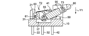
- FIG. 8 is a diagram for explaining a method of assembling the switch of FIG. 1 following FIG. 7. It is a figure for demonstrating operation
- FIG. 10 is a diagram for explaining the operation of the switch of FIG. 1 following FIG. 9.
- FIG. 11 is a diagram for explaining the operation of the switch of FIG. 1 following FIG. 10.
- FIG. 12 is a diagram for explaining the operation of the switch of FIG. 1 following FIG. 11.
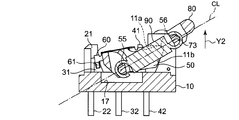
- FIG. 13 is a diagram for explaining the operation of the switch of FIG. 1 following FIG. 12.
- FIG. 14 is a diagram for explaining the operation of the switch of FIG. 1 following FIG. 13. It is a figure for demonstrating other embodiment of the switch of FIG. It is another figure for demonstrating other embodiment of the switch of FIG. It is another figure for demonstrating other embodiment of the switch of FIG. It is another figure for demonstrating other embodiment of the switch of FIG.
- the switch 100 includes a base 10, an operating lever 70 as an example of a sliding body 50 and an operating body provided on the base 10, and the base 10. And a cover 80 that covers the sliding body 50.
- the base 10 is provided with two sets of a first fixed contact terminal 20, a second fixed contact terminal 30, and a common fixed contact terminal 40.
- Two movable contact pieces 60 are attached to the sliding body 50.
- the switch 100 further includes a reversing spring 90 as an example of an elastic body connected to the sliding body 50 and the operation lever 70, and two return springs 91 connected to the base 10 and the operation lever 70. .
- the base 10 has a rectangular shape in a top view defined by a pair of long sides and a pair of short sides, as shown in FIGS.
- the base 10 is provided with a pair of support portions 11 for supporting the sliding body 50 and the operation lever 70.
- the pair of support portions 11 are provided at the edge of one short side of the upper surface of the base 10 so as to protrude from the upper surface of the base 10. It arrange
- the support portion 11 includes a vertical portion extending upward from the upper surface of the base 10 and a horizontal portion extending in the longitudinal direction of the base 10 along the upper surface of the base 10 from the upper end of the vertical portion.
- a notch portion 12 is provided at a connecting portion between the lower surface 11 a of the horizontal portion and the side surface 11 b of the vertical portion continuing to the lower surface 11 a.
- the notch 12 is disposed on an outward surface not facing the other support 11, and a rotation receiving portion 13 that rotatably supports the slide 50 and a slide attachment hole for attaching the slide 50. 14.
- the lower surface 11a of the horizontal portion of the support portion 11 and the side surface 11b of the vertical portion continuing to the lower surface 11a are inclined so that the rotation range of the sliding body 50 can be defined.
- a base projection 15 protruding from the outward surface of the support portion 11 is provided above the notch portion 12 of the support portion 11, and a spring for attaching one end of the return spring 91 to the base portion (lower end) of the vertical portion.
- a mounting hole 16 is provided.
- a recess 10 a corresponding to the shape of the cover 80 is provided at the outer peripheral edge of the upper surface of the base 10, and a recess 17 having a rectangular shape in top view is provided at the center of the upper surface of the base 10.
- two attachment projections 18 for attaching the cover 80 are provided at predetermined intervals on each side surface parallel to the longitudinal direction of the base 10.
- the first fixed contact terminal 20, the second fixed contact terminal 30, and the common fixed contact terminal 40 are plate-like bodies formed by punching one conductive plate, as shown in FIGS. It is provided at the edge of the long side by insert molding.
- the first fixed contact terminal 20, the second fixed contact terminal 30, and the common fixed contact terminal 40 are aligned and arranged in a line, and the second fixed contact terminal 20 and the common fixed contact terminal 40 are second fixed.
- the contact terminals 30 are located and arranged so as to be separated from each other.
- the first fixed contact terminal 20, the second fixed contact terminal 30, and the common fixed contact terminal 40 arranged in a line constitute the switch units SW1 and SW2.
- the first fixed contact terminal 20 has a first fixed contact 21 provided on the upper surface side of the base 10 and a first fixed terminal 22 provided on the bottom surface side of the base 10, and the second fixed contact terminal 30 is The second fixed contact 31 provided on the upper surface side of the base 10 and the second fixed terminal 32 provided on the bottom surface side of the base 10 are provided.
- the common fixed contact terminal 40 has a common fixed contact 41 provided on the upper surface side of the base 10 and a common fixed terminal 42 provided on the bottom surface side of the base 10.
- the first and second fixed contacts 21 and 31 are examples of open / close fixed contacts.
- the first fixed contacts 21 are disposed at both ends of the short side of the upper surface of the base 10 facing the support portion 11 and protrude upward from the upper surface of the base 10.
- the first fixed contact 21 includes a vertical portion extending upward from the upper surface of the base 10 and a horizontal portion extending from the upper end portion of the vertical portion toward the support portion 11.
- the vertical portion of the first fixed contact 21 is covered with an insulating member 23, and the horizontal portion is exposed.
- the second fixed contact 31 is disposed below the horizontal portion of the first fixed contact 21 and protrudes upward from the upper surface of the base 10.
- the horizontal portion of the first fixed contact 21 and the second fixed contact 31 are integrated with each other through an insulating portion 33 to form one plate-like body.
- This plate-like body has no step between the surfaces of the first fixed contact 21, the insulating portion 33 and the second fixed contact 31, and is formed flush. Further, the common fixed contact 41 is disposed so as to be positioned between the first and second fixed contacts 21, 31 and the support portion 11, and protrudes upward from the upper surface of the base 10.
- the first fixed terminal 22, the second fixed terminal 32, and the common fixed terminal 42 are arranged at a predetermined interval and project downward from the bottom surface of the base 10.
- the sliding body 50 includes a main body portion 51 and two arm portions 52 extending in parallel with an interval from both ends of one side surface of the main body portion 51.
- the main body 51 has a substantially rectangular shape when viewed from above, as shown in FIG.
- Sliding body through holes 53 are provided at both ends of the upper surface of the main body 51 in the longitudinal direction.
- Each of the sliding body through holes 53 has a rectangular shape having a long side extending in the short direction of the main body 51 and a short side extending in the longitudinal direction.
- Protruding portions 54 extending from the upper surface of the main body 51 toward the bottom surface are provided on both side surfaces in the longitudinal direction of the main body 51.
- an attachment shaft portion 55 for attaching one end of the reversing spring 90 is provided on the side surface of the main body portion 51 where the arm portion 52 is provided.
- Each of the arm parts 52 has a sliding body rotating shaft part 56 at the tip thereof.
- the sliding body rotation shaft portion 56 has a shape that can be stored in the rotation receiving portion 13 of the base 10, and is provided so that a contact portion with the rotation receiving portion 13 becomes a rotation fulcrum of the sliding body 50.
- a sliding body protrusion 57 is provided on the inward surface facing the other arm portion 52 of the sliding body rotation shaft portion 56.
- the sliding body protrusion 57 has a shape that can be fitted into the sliding body mounting hole 14 of the support portion 11 of the base 10.
- the sliding body mounting hole 14 of the base 10 and the sliding body protrusion 57 of the sliding body 50 constitute a temporary fixing mechanism for temporarily fixing the sliding body 50 to the base 10.
- the movable contact piece 60 has a rectangular shape in a top view formed by punching and bending one conductive spring plate.
- the movable contact piece 60 includes a pair of first movable contacts 61 and a pair of second movable contacts 62 provided at both ends, and an attachment mechanism portion provided between the first and second movable contacts 61 and 62. When it is attached to the sliding body 50, it is formed so that it can move with play in the short direction.
- the first movable contact 61 is an example of an open / close movable contact
- the second movable contact 62 is an example of a common movable contact.
- the first movable contact 61 has a shape capable of elastically holding the first and second fixed contacts 21 and 31 along the longitudinal direction of the movable contact piece 60.
- the second movable contact 62 has a shape capable of elastically holding the common fixed contact along the longitudinal direction of the movable contact piece 60.
- the first and second movable contacts 61 and 62 are arranged so that either the first or second fixed contact 21 or 31 and the common fixed contact 41 can be elastically sandwiched simultaneously.
- the attachment mechanism portion of the movable contact piece 60 includes an insertion portion 63 to be inserted into the slide body through hole 53 of the slide body 50 and an elastic arm portion 65 for fixing the movable contact piece 60 to the slide body 50.
- the insertion portion 63 is in a rectangular plate state and extends from one side surface in the short direction of the movable contact piece 60 in a direction orthogonal to the upper surface of the movable contact piece 60.
- a locking claw portion 64 is provided at the center of the lower end of the insertion portion 63.
- the elastic arm portion 65 has a bifurcated shape that can sandwich the protruding portion 54 of the sliding body 50, and faces the insertion portion 63 from the other side surface in the short direction of the movable contact piece 60.
- a locking claw portion 66 is provided at the tip of the elastic arm portion 65.
- Each of the locking claws 64 and 66 has a shape that can be locked to the bottom surface of the sliding body 50 when the movable contact piece 60 is attached to the sliding body 50.
- a protrusion 67 is provided between the first and second movable contacts 61 and 62 on the upper surface of the movable contact piece 60 and the attachment mechanism portion to increase the rigidity.
- the operation lever 70 includes an operation member 71 and a pair of lever support portions 72 provided at both ends of one surface of the operation member 71.
- the operation member 71 is a rectangular plate-like body and has one curved surface in the short direction. As shown in FIG. 4, an attachment shaft portion 73 for attaching one end of the reversing spring 90 is provided between the lever support portions 72 on the surface facing the curved surface.
- Each of the lever support portions 72 has an operation lever rotating shaft portion 74, respectively.
- the operation lever rotation shaft portion 74 has a cylindrical shape, and is provided so that the center thereof becomes a rotation fulcrum of the operation lever 70. That is, one operation lever rotation shaft portion 74 and the other operation lever rotation shaft portion 74 extend in the opposite direction along the longitudinal direction of the operation member 71, and the central axes of both are on the same straight line. It is arranged to be located.
- Temporary fixing holes 75 are provided at both ends of the operation lever rotating shaft portion 74 in the axial direction.
- the temporary fixing hole 75 penetrates in the axial direction of the operation lever rotation shaft portion 74 and has a shape that can be fitted to the base protrusion 15 of the support portion 11 of the base 10.
- the base protrusion 15 of the base 10 and the temporary fixing hole 75 of the operating lever 70 constitute a temporary fixing mechanism for temporarily fixing the operating lever 70 to the base 10.
- a part of the operation member 71 constitutes an example of the operation part, and a part of the operation member 71, the lever support part 72, and the attachment shaft part 73 constitute an example of the rotation part. That is, in the operation lever 70, the rotating part and the operation part are integrally formed.
- a step 76 is provided between the operation member 71 and the lever support 72.
- An operation lever through hole 77 for attaching one end of the return spring 91 is provided on the lever support portion 72 on the operation member 71 side.
- the cover 80 has a substantially rectangular parallelepiped shape with an open bottom surface and attachable to the base 10.
- the cover 80 has a cover attachment hole 81 for attaching the cover 80 to the base 10, a support hole 82 for rotatably supporting the operation lever 70, and an operation for enabling operation of the operation lever 70.
- An opening 83 is provided.
- the cover mounting hole 81 is disposed at the opening side edge on both side surfaces of the cover 80 in the short direction, and has a shape that can be fitted to the mounting protrusion 18 of the base 10.
- the support hole 82 has a shape that can be fitted to the operation lever rotation shaft portion 74 of the operation lever 70.
- the support hole 82 is disposed at one corner on the upper surface side of both side surfaces of the cover 80 in the short direction, and supports the operation lever rotation shaft portion 74 so as to be rotatable.
- the operation opening 83 is open to a part of the side surface and the upper surface on the side where the support hole 82 is provided among the side surfaces in the longitudinal direction of the cover 80.
- the reverse spring 90 and the return spring 91 are made of, for example, carbon steel or stainless steel.
- the reversing spring 90 is a coil spring, and both ends have shapes that can be attached to the attachment shaft portion 55 of the sliding body 50 and the attachment shaft portion 73 of the operation lever 70.
- the reversing spring 90 is adjusted in spring length so that when the reversing spring 90 is attached to the sliding body 50 and the operation lever 70, an elastic force always acts in a direction in which both are pulled.
- the return spring 91 is a torsion spring, and both ends thereof are bent in the same direction, and one end thereof has a shape that can be attached to the spring attachment hole 16 of the base 10.
- the return spring 91 is formed with an annular portion 92 having an inner diameter into which the operation lever rotating shaft portion 74 of the operation lever 70 can be inserted.
- FIG. 1 A method for assembling the switch 100 having the above-described configuration will be described with reference to FIGS. 1, 2, and 5 to 8.
- FIG. 1 A method for assembling the switch 100 having the above-described configuration will be described with reference to FIGS. 1, 2, and 5 to 8.
- the sliding body 50 having the two movable contact pieces 60 attached thereto is temporarily fixed to the base 10 provided with the two sets of switch portions SW ⁇ b> 1 and SW ⁇ b> 2.
- the sliding body 50 fits the sliding body protrusion 57 into the sliding body mounting hole 14 of the base 10, and the first movable contact 61 of the movable contact piece 60 is the first fixed contact 21.
- the second movable contact 62 is temporarily fixed to the base 10 with the common fixed contact 41 held therebetween.
- the movable contact piece 60 is attached to be movable in a short direction, that is, in a state where there is play in the rotational axis direction of the sliding body 50, and the pair of first movable contacts 61 and the pair of second movable contacts 62. Is attached in the direction of the rotational axis of the sliding body 50. For this reason, even if there is an error between the positions of the provided switch parts SW1 and SW2 and the designed positions of the switch parts SW1 and SW2, when the sliding body 50 is attached to the base 10, the movable contact The piece 60 moves according to the positions of the switch portions SW1 and SW2, and the position of the movable contact piece 60 is automatically adjusted. As a result, since it is not necessary to strictly manage the positioning accuracy of the switch units SW1 and SW2, the manufacturing cost can be reduced.
- the base protrusion 15 (shown in FIGS. 5 and 6) of the base 10 is fitted into the temporary fixing hole 75 of the operation lever 70 to temporarily fix the operation lever 70 to the base 10. .
- the sliding body 50 and the operating lever 70 are temporarily fixed to the base 10, as shown in FIG. 8, one end of the reversing spring 90 is attached to the mounting shaft portion 55 of the sliding body 50, while the other end of the reversing spring 90 is operated.
- the sliding body 50 and the operation lever 70 are connected to each other by attaching to the mounting shaft portion 73 of the lever 70 via the reversing spring 90.
- the reversing spring 90 is attached, the sliding body 50 is attracted to the operating lever 70 and biased away from the base 10 by the reversing spring 90.
- the sliding body 50 has the sliding body rotation shaft portion 56 in contact with the rotation receiving portion 13 of the base 10 and is rotatably supported by the base 10, and at the horizontal portion of the support portion 11 of the base 10. It is held in a first operating position defined by the lower surface 11a.
- the first operating position means that the first movable contact 61 contacts the first fixed contact 21, the second movable contact 62 contacts the common fixed contact 41, and the first fixed contact 21, the common fixed contact 41, Is the position of the sliding body 50 that makes the two conductive.
- one end of the return spring 91 is attached to the spring mounting hole 16 of the base 10 so that the operation lever rotation shaft portion 74 is inserted into the annular portion 92 of the return spring 91.
- the other end is attached to the operation lever through hole 77 of the operation lever 70.
- the mounting protrusion 18 of the base 10 is fitted into the cover mounting hole 81 of the cover 80, the cover 80 is mounted on the base 10, and the assembly process of the switch 100 is completed.
- the cover 80 is attached to the base 10 so that the operation lever rotating shaft portion 74 of the operation lever 70 is fitted into the support hole 82 and the operation lever 70 protrudes from the operation opening 83 of the cover 80 so as to be operable. It is done.
- the sliding body 50 and the operation lever 70 can be temporarily fixed to the base 10, so that the switch 100 can be temporarily fixed even in a semi-finished product. For this reason, the assembly of the switch 100 becomes easy, and the productivity can be enhanced.
- the switch 100 has two sets of switch units SW1 and SW2, and switches these switch units SW1 and SW2 substantially simultaneously.
- the sliding body 50 When torque T ⁇ b> 2 is applied to the sliding body 50, the sliding body 50 is biased in a direction approaching the base 10 by the elasticity of the reversing spring 90, and the sliding body 50 rotates counterclockwise about the sliding body rotating shaft portion 56. Starts turning. Then, as shown in FIG. 11, the sliding body 50 rotates to the second operation position defined by the side surface 11 b of the vertical portion that is continuous with the lower surface 11 a of the horizontal portion of the support portion 11 and stops.
- the second operation position means that the first movable contact 61 contacts the second fixed contact 31, the second movable contact 62 contacts the common fixed contact 41, and the second fixed contact 31, the common fixed contact 41, Is the position of the sliding body 50 that makes the two conductive.
- the first movable contact 61 of the movable contact piece 60 slides on the surface of the plate-like body in the Y1 direction while holding the plate-like body composed of the first and second fixed contacts 21 and 31.
- the second movable contact 62 slides on the surface of the common fixed contact 41 in the Y1 direction while holding the common fixed contact 41 therebetween. That is, the first movable contact 61 that has been in contact with the first fixed contact 21 by the rotation of the sliding body 50 slides from the first fixed contact 21 to the second fixed contact 31 through the insulating portion 33, The two movable contacts 62 slide on the surface of the common fixed contact 41.
- the operation lever 70 is pushed down to the position shown in FIG. 12, contacts the support portion 11 of the base 10, and stops.
- the sliding body 50 and the operation lever 70 rotatably supported by the base 10 are connected by the reversing spring 90, and when the operation lever 70 is rotated to a predetermined position, the sliding force 50 is slid by the elastic force of the reversing spring 90.
- the moving body 50 rotates and contacts or separates the first movable contact 61 and the first and second fixed contacts 21 and 31. That is, since the conduction path is directly switched by the external force applied to the operation lever 70, parts such as an actuator are not required to transmit the external force to the operation lever 70. For this reason, the number of parts and assembly man-hours of the switch 100 can be reduced, and the productivity can be increased.
- the sliding body 50 is rotated by the snap action operation by the elastic force of the reversing spring 90 when the operation lever 70 is rotated to a predetermined position, and the first movable contact 61 and the first and first contacts
- the first movable contact 61 is slid so that the second fixed contacts 21 and 31 are brought into contact with or separated from each other, and the second movable contact 62 is slid while maintaining the state in contact with the common fixed contact 41. For this reason, impurities and the like generated on the surfaces of the first and second movable contacts 61 and 62 and the fixed contacts 21, 31, and 41 are scraped off, so that a wiping effect can be obtained and contact reliability can be improved. .
- the switch units SW1 and SW2 are switched, the second movable contact 62 slides while being in contact with the common fixed contact 41 by the rotation of the sliding body 50. For this reason, even if it has three or more switch parts, all the switch parts can be switched substantially simultaneously.
- the sliding body 50 and the operation lever 70 have different rotation fulcrums.
- the operation lever rotation shaft portion 74 serving as the rotation fulcrum of the operation lever 70 is provided on the upper portion of the slide body rotation shaft portion 56 serving as the rotation fulcrum of the slide body 50. Therefore, it is possible to reduce the pressing force in the Y1 direction of the operating lever 70 necessary for rotating the sliding body 50, compared to a switch in which the sliding fulcrum of the sliding body 50 and the operating lever 70 is at the same position. That is, the driving force for the large sliding body 50 can be obtained by the pressing force for the small operating lever 70. As a result, even if three or more sets of switch units are provided, the switch units can be easily switched.
- the rotation range of the sliding body 50 is defined by the lower surface 11a of the horizontal portion of the support portion 11 and the side surface 11b of the vertical portion continuous to the lower surface 11a.
- the sliding body 50 rotated by switching between the switch units SW1 and SW2 is a horizontal portion of the support portion 11 located in the vicinity of the sliding body rotation shaft portion 56 serving as a rotation fulcrum of the sliding body 50, and It collides with the vertical part and stops.
- the horizontal portion and the vertical portion of the support portion 11 are disposed in the vicinity of the slide body rotation shaft portion 56 that serves as the rotation fulcrum of the slide body 50, the collision is low when the slide body 50 rotates. It collides with the horizontal part and the vertical part of the support part 11 at a speed. For this reason, the noise by the sliding body 50 colliding with the horizontal part and the vertical part of the support part 11 can be reduced.
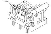
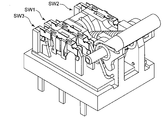
- the switch unit is not limited to two sets, but may be one set (SW1) as shown in FIG. 15, or three sets (SW1 to SW3) as shown in FIG. Although not shown, four or more sets may be used.
- the switch portions are not limited to being arranged in a line, and may be arranged so that the fixed contacts are not aligned on a straight line.
- the sliding body 50 and the operation lever 70 are connected by the reversing spring 90, and the conduction path is directly switched by the external force applied to the operation lever 70.
- the present invention is not limited to this. That is, according to the present invention, the opening / closing movable contact slides and the common movable contact is fixed in common so that the opening / closing movable contact and at least one opening / closing fixed contact are contacted or separated by rotation of the sliding body. Any switch can be used as long as it slides while maintaining the contact state.
- a reversing spring may be attached in a state where the base, the sliding body and the operation lever are assembled, and the base, the sliding body and the operation lever can be assembled in any order.
- a metal material may be inserted into the rotation receiving portion 13 of the base 10. Thereby, the intensity
- the plate-like body composed of the first and second fixed contacts 21 and 31 and the common fixed contact 41 can be slid in a state where the first and second movable contacts 61 and 62 are in contact with each other by the rotation of the slide body 50. Any size and shape may be used, and any size and shape can be adopted.
- the sliding body 50 may be integrally formed with a sliding body through-hole into which the movable contact piece is inserted, a sliding body rotating shaft portion, and an attachment shaft portion for fixing one end of the reversing spring, or may be formed separately.
- the sliding body may be formed by connecting with an adhesive or the like.
- the attachment shaft portion 55 that fixes one end of the reversing spring 90 may be formed of a metal material. Thereby, the intensity
- the movable contact piece 60 is fixed by inserting the insertion portion 63 into the sliding body through-hole 53 of the sliding body 50, but is not limited thereto.
- the movable contact piece 60 may be formed integrally with the sliding body 50 by insert molding, or may be fixed to the sliding body 50 by thermal caulking. Thereby, the fixed strength of the movable contact piece 60 with respect to the sliding body 50 can be raised.
- the operation lever 70 may be formed integrally with the operation member and the lever support portion, or may be formed separately and connected with an adhesive or the like to form the operation lever. Further, the attachment shaft portion 73 that fixes one end of the reversing spring 90 may be formed of a metal material. Thereby, the intensity
- the operation body is not limited to the operation lever 70, and any operation body can be used as long as it can rotate the slide body 50.
- the shape, size, number of parts, and the like are arbitrary depending on the design of the switch. Can be set.
- the operating body is not limited to the one that is rotatably supported, but may be one that is supported to be linearly movable.
- the operation lever 70 in which the operation unit and the rotation unit are integrally formed but the operation unit and the rotation unit may be separately formed and connected.
- an actuator that transmits an external force to the rotating unit and an operation member for operating the actuator may be used.
- any material can be used for the reversing spring 90 as long as it exhibits an elastic force according to the design of the switch 100.
- a coil spring not only a coil spring but a leaf
- the return spring 91 may be made of any material as long as it exerts an elastic force that returns the operation lever 70 to the return position against the elastic force of the reversing spring 90 when the operation lever 70 is pushed down. Can do. Moreover, not only a torsion spring but a coil spring, a leaf
- the temporary fixing mechanism for temporarily fixing the sliding body 50 and the operation lever 70 to the base 10 may be any mechanism as long as it can be temporarily fixed with the sliding body 50 and the operation lever 70 attached to the base 10. Not limited to.
- a convex portion may be provided on the base, and a concave portion that can be fitted to the convex portion may be provided on the sliding body.
- the base may be provided with a concave portion, and the operation lever may be provided with a convex portion that can be fitted into the concave portion.
- the switch of the present invention can be used, for example, in an electronically controlled parking brake of an automobile.
Landscapes
- Rotary Switch, Piano Key Switch, And Lever Switch (AREA)
- Push-Button Switches (AREA)
Abstract
スイッチ(100)が、ベース(10)と、共通固定接点(41)および第1,第2固定接点(21,31)を有するスイッチ部(SW1,SW2)と、共通固定接点(41)に接触する第2可動接点(62)と、共通可動接点(62)に導通し、かつ、第1,第2固定接点(21,31)に接触する第1可動接点(61)とを有し、ベース(10)に移動可能に支持された摺動体(50)と、ベース(10)に取り付けられたカバー(80)と、カバー(80)に支持され摺動体(50)を回動させる操作レバー(70)と、摺動体(50)と操作レバー(70)とを互いに近づく方向に付勢する反転ばね(90)と、を備えている。摺動体(50)の回動によって、第1可動接点(61)が、第1,第2固定接点(21,31)と接触または開離するようにスライド移動すると共に、第2可動接点(62)が、共通固定接点(41)に接触した状態を維持したままスライド移動する。
Description
本発明は、スイッチに関する。
従来、スイッチとしては、例えば、特許文献1に記載されたものがある。このスイッチは、操作部材と、コモン接点および第1,第2切替接点からなる固定接点と、コモン接点に当接すると共に第1,第2切替接点のいずれかに接触する接点部を有する可動接点と、操作部材の押圧操作によって第1,第2切替接点に接触する可動接点を移動させるためのスナップアクション機構と、を備えている。
前記従来のスイッチは、可動接点を切替接点に摺接させ、これにより接触信頼性の高いスイッチを提供している。本発明者は、前記従来のスイッチよりもさらに接触信頼性の高いスイッチが得られることを見出した。
そこで、本発明は、接触信頼性の高いスイッチを提供することを課題とする。
本発明のスイッチは、前記課題を解決すべく、ベースと、互いに所定の間隔を空けて配置された、共通固定接点および少なくとも1つの開閉用固定接点を有し、前記ベースに設けられた少なくとも1つのスイッチ部と、前記共通固定接点に摺動可能に接触する共通可動接点と、前記共通可動接点に導通し、かつ、前記開閉用固定接点に摺動可能に接触または開離する開閉用可動接点とを有し、前記ベースに回動可能に支持された摺動体と、前記スイッチ部および前記摺動体を覆うように前記ベースに取り付けられたカバーと、前記ベースまたは前記カバーに移動可能に支持された操作体と、前記摺動体と前記操作体とを互いに近づく方向に付勢する弾性体と、を備える。前記摺動体は、前記操作体を所定の位置まで移動させたときに前記弾性体の弾性力によるスナップアクション動作により回動するように支持されており、前記開閉用可動接点は、前記摺動体の回動に伴い、前記開閉用固定接点と接触または開離するようにスライド移動し、前記共通可動接点は、前記摺動体の回動に伴い、前記共通固定接点に接触した状態を維持したままスライド移動する。
本発明のスイッチによれば、操作体を所定の位置まで移動させたときに弾性体の弾性力によるスナップアクション動作により摺動体が回動し、この摺動体の回動に伴って、開閉用可動接点と開閉用固定接点とを接触または開離させるように開閉用可動接点をスライド移動させると共に、共通固定接点に接触した状態を維持しつつ共通可動接点をスライド移動させる。このため、第1,第2の可動接点および各固定接点の表面上に生成された不純物等が擦り取られ、ワイピング効果を得ることができ、その結果、接触信頼性を向上できる。
また、摺動体の回動によって、第2の可動接点が共通固定接点に接触した状態のままスライド移動する。このため、複数のスイッチ部を有していたとしても、全てのスイッチ部を略同時に切り替えることができる。
本発明の一実施形態としては、前記操作体が、前記ベースまたは前記カバーに回動可能に支持された回動部と、この回動部に連結された操作部とを有し、前記摺動体および前記回動部が、異なる回動支点を有するように配置されている構成としてもよい。
この実施形態によれば、摺動体および回動部が、異なる回動支点を有しているので、摺動体および回動部の回動支点が同じ位置にあるスイッチと比較して、摺動体を回動させるために必要な操作体の押圧力を低減できる。すなわち、小さな操作体に対する押圧力で、大きな摺動体に対する駆動力を得ることができる。その結果、スイッチ部を容易に切り替えることができる。
本発明の一実施形態としては、前記摺動体が、一対の前記開閉用可動接点と一対の前記共通可動接点とが設けられた可動接触片を有し、前記一対の開閉用可動接点および前記一対の共通可動接点の各々が、前記摺動体の回動軸方向に取り付けられ、かつ、移動可能に取り付けられると共に、前記開閉用固定接点および前記共通固定接点を弾性挟持している構成としてもよい。
この実施形態によれば、設けられたスイッチ部の位置と設計上のスイッチ部の位置との間に誤差が生じていたとしても、摺動体をベースに取り付けたときに可動接触片がスイッチ部の位置に合わせて移動し、可動接触片の位置が自動調整される。このため、スイッチ部の位置決め精度を厳しく管理する必要がないので、製造コストを低減できる。
以下、添付図面を参照して本発明のスイッチの実施形態を説明する。なお、以下の説明では、図面に表された構成を説明するうえで、「上」、「下」、「左」、「右」等の方向を示す用語、及びそれらを含む別の用語を使用するが、それらの用語を使用する目的は図面を通じて実施形態の理解を容易にするためである。したがって、それらの用語は本発明の実施形態が実際に使用されるときの方向を示すものとは限らないし、それらの用語によって特許請求の範囲に記載された発明の技術的範囲が限定的に解釈されるべきでない。
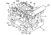
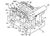
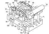
本発明の一実施形態のスイッチ100は、図1,図2に示すように、ベース10と、このベース10上に設けられた摺動体50および操作体の一例の操作レバー70と、ベース10上に設けられ摺動体50を覆うカバー80とを備えている。
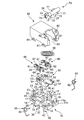
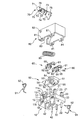
図3に示すように、ベース10には、2組の第1固定接点端子20、第2固定接点端子30および共通固定接点端子40が設けられている。摺動体50には、2つの可動接触片60が取り付けられている。また、スイッチ100には、摺動体50および操作レバー70に連結された弾性体の一例の反転ばね90と、ベース10および操作レバー70に連結された2つの復帰ばね91とがさらに設けられている。
ベース10は、図3~図5に示すように、一対の長辺および一対の短辺で画定される上面視矩形状を有している。このベース10には、摺動体50および操作レバー70を支持するための一対の支持部11が設けられている。
一対の支持部11は、図3,図5に示すように、ベース10の上面の一短辺の縁部に、ベース10の上面から突出するように設けられ、各支持部11が、ベース10の短辺に沿って互いに対向するように配置されている。
支持部11は、ベース10の上面から上方に延びる鉛直部と、鉛直部の上端からベース10の上面に沿ってベース10の長手方向に延びる水平部とで構成されている。水平部の下面11aと、この下面11aに連続する鉛直部の側面11bとの連結部分には、図4に示すように、切欠部12が設けられている。この切欠部12は、他方の支持部11に面していない外向面に配置され、摺動体50を回動可能に支持する回動受部13と、摺動体50を取り付けるための摺動体取付孔14とを有している。支持部11の水平部の下面11aと、この下面11aに連続する鉛直部の側面11bとは傾斜しており、摺動体50の回動範囲を画定できるようになっている。
また、支持部11の切欠部12の上方には、支持部11の外向面から突出するベース突起15が設けられ、鉛直部の基部(下端)には、復帰ばね91の一端を取り付けるためのばね取付孔16が設けられている。
ベース10の上面の外周縁部には、カバー80の形状に応じた凹部10aが設けられ、ベース10の上面の中央部には、上面視矩形状の凹部17が設けられている。また、ベース10の長手方向に平行な側面の各々には、カバー80を取り付けるための2つの取付突部18が、所定の間隔を空けて設けられている。
第1固定接点端子20、第2固定接点端子30および共通固定接点端子40は、図3~図5に示すように、1枚の導電板を打ち抜いて形成した板状体であり、ベース10の長辺の縁部にインサート成形により設けられている。この第1固定接点端子20、第2固定接点端子30および共通固定接点端子40は、一列に整列配置されていると共に、第1固定接点端子20と共通固定接点端子40との間に第2固定接点端子30が位置し、かつ、互いに離間するように配置されている。なお、一列に整列配置された第1固定接点端子20、第2固定接点端子30および共通固定接点端子40で、スイッチ部SW1,SW2を構成している。
第1固定接点端子20は、ベース10の上面側に設けられた第1固定接点21と、ベース10の底面側に設けられた第1固定端子22とを有し、第2固定接点端子30は、ベース10の上面側に設けられた第2固定接点31と、ベース10の底面側に設けられた第2固定端子32とを有している。また、共通固定接点端子40は、ベース10の上面側に設けられた共通固定接点41と、ベース10の底面側に設けられた共通固定端子42とを有している。なお、第1,第2固定接点21,31は、開閉用固定接点の一例である。
第1固定接点21は、ベース10の上面の支持部11に対向する側の短辺の両端に配置され、ベース10の上面から上方に突出している。この第1固定接点21は、ベース10の上面から上方に延びる鉛直部分と、この鉛直部分の上端部から支持部11に向かって延びる水平部分とで構成されている。第1固定接点21の鉛直部分は、絶縁部材23で覆われており、水平部分が露出している。第2固定接点31は、第1固定接点21の水平部分の下方に配置され、ベース10の上面から上方に突出している。第1固定接点21の水平部分と第2固定接点31とは、絶縁部33を介して一体化され、1つの板状体を形成している。この板状体は、第1固定接点21、絶縁部33および第2固定接点31の表面の間に段差がなく、面一に形成されている。また、共通固定接点41は、第1,第2固定接点21,31と支持部11との間に位置するように配置され、ベース10の上面から上方に突出している。
第1固定端子22、第2固定端子32および共通固定端子42は、図4に示すように、所定の間隔を空けて配置されており、それぞれ、ベース10の底面から下方に突出している。
摺動体50は、図3,図4に示すように、本体部51と、この本体部51の一側面の両端から間隔を空けて平行に延びる2つの腕部52とで構成されている。
本体部51は、図3に示すように、上面視略矩形状を有している。本体部51の上面の長手方向の両端には、摺動体貫通孔53が設けられている。この摺動体貫通孔53は、それぞれ、本体部51の短手方向に延びる長辺と長手方向に延びる短辺とを有する矩形状を有している。本体部51の長手方向の両側面には、本体部51の上面から底面に向かって延びる突出部54が設けられている。また、図4,図9に示すように、本体部51の腕部52が設けられた側面には、反転ばね90の一端を取り付けるための取付軸部55が設けられている。
腕部52は、その先端に、それぞれ、摺動体回動軸部56を有している。この摺動体回動軸部56は、ベース10の回動受部13に収納可能な形状を有し、回動受部13との接触部分が摺動体50の回動支点となるように設けられている。また、摺動体回動軸部56の他方の腕部52に面する内向面に、摺動体突起57が設けられている。この摺動体突起57は、ベース10の支持部11の摺動体取付孔14に嵌合可能な形状を有している。なお、ベース10の摺動体取付孔14と摺動体50の摺動体突起57とで、ベース10に摺動体50を仮止めするための仮止め機構を構成している。
可動接触片60は、図3,図4に示すように、1枚の導電性ばね板を打ち抜き折り曲げて形成した上面視矩形状を有している。この可動接触片60は、両端に設けられた一対の第1可動接点61および一対の第2可動接点62と、この第1,第2可動接点61,62の間に設けられた取付機構部とで構成され、摺動体50に取り付けたときに、短手方向に遊びを持った状態で移動できるように形成されている。なお、第1可動接点61は、開閉用可動接点の一例であり、第2可動接点62は、共通可動接点の一例である。
第1可動接点61は、可動接触片60の長手方向に沿って第1,第2固定接点21,31を弾性挟持可能な形状を有している。また、第2可動接点62は、可動接触片60の長手方向に沿って共通固定接点を弾性挟持可能な形状を有している。この第1,第2可動接点61,62は、第1,第2固定接点21,31のいずれかと共通固定接点41とを同時に弾性挟持できるように配置されている。
可動接触片60の取付機構部は、摺動体50の摺動体貫通孔53に挿入する挿入部63と、可動接触片60を摺動体50に固定するための弾性腕部65とで構成されている。挿入部63は、矩形の板状態で、可動接触片60の短手方向の一方の側面から、可動接触片60の上面の直交方向に延びている。この挿入部63の下端中央には、係止爪部64が設けられている。また、弾性腕部65は、摺動体50の突出部54を間に挟むことができる二股形状を有し、可動接触片60の短手方向の他方の側面から、挿入部63に対向するように延びている。この弾性腕部65の先端には、係止爪部66が設けられている。係止爪部64,66は、それぞれ、可動接触片60を摺動体50に取り付けたときに、摺動体50の底面に係止可能な形状を有している。
また、可動接触片60の上面の第1,第2可動接点61,62と取付機構部との間には、剛性を高めるための突起67が設けられている。
操作レバー70は、図3,図4に示すように、操作部材71と、操作部材71の一面の両端に設けられた一対のレバー支持部72とで構成されている。
操作部材71は、矩形の板状体であり、短手方向に1つの曲面を有している。また、図4に示すように、曲面に対向する面のレバー支持部72の間には、反転ばね90の一端を取り付けるための取付軸部73が設けられている。
レバー支持部72の各々は、操作レバー回動軸部74をそれぞれ有している。操作レバー回動軸部74は、円筒形状を有し、その中心が操作レバー70の回動支点となるように設けられている。すなわち、一方の操作レバー回動軸部74と他方の操作レバー回動軸部74とが、操作部材71の長手方向に沿って互いに対向方向に延びており、両者の中心軸が同一直線上に位置するように配置されている。操作レバー回動軸部74の軸心方向の両端には、仮止め孔75が設けられている。仮止め孔75は、操作レバー回動軸部74の軸心方向に貫通しており、ベース10の支持部11のベース突起15に嵌合可能な形状を有している。なお、ベース10のベース突起15と操作レバー70の仮止め孔75とで、ベース10に操作レバー70を仮止めするための仮止め機構を構成している。
なお、操作部材71の一部が操作部の一例を構成し、操作部材71の一部とレバー支持部72と取付軸部73とが回動部の一例を構成している。すなわち、この操作レバー70では、回動部と操作部とが一体に形成されている。
操作部材71とレバー支持部72との間には、段部76が設けられている。また、レバー支持部72の操作部材71側には、復帰ばね91の一端を取り付けるための操作レバー貫通孔77が設けられている。
カバー80は、図3,図4に示すように、底面が開口し、ベース10に取り付け可能な略直方体形状を有している。このカバー80には、カバー80をベース10に取り付けるためのカバー取付孔81と、操作レバー70を回動可能に支持するための支持孔82と、操作レバー70の操作を可能にするための操作開口83とが設けられている。
カバー取付孔81は、カバー80の短手方向の両側面の開口側縁部に配置され、ベース10の取付突部18に嵌合可能な形状を有している。支持孔82は、操作レバー70の操作レバー回動軸部74に嵌合可能な形状を有している。この支持孔82は、カバー80の短手方向の両側面の上面側の1つの隅部に配置され、操作レバー回動軸部74を回動可能に支持している。また、操作開口83は、カバー80の長手方向の側面のうち、支持孔82が設けられている側の側面および上面の一部に開口している。
反転ばね90および復帰ばね91は、例えば、炭素鋼あるいはステンレス鋼からなっている。反転ばね90はコイルばねであり、両端部の各々が、摺動体50の取付軸部55および操作レバー70の取付軸部73に取り付け可能な形状を有している。また、反転ばね90は、反転ばね90を摺動体50および操作レバー70に取り付けたときに、常に両者を引き寄せる方向に弾性力が働くようばね長が調整されている。復帰ばね91はトーションばねであり、両端部が同一方向に折り曲げられ、一端部が、ベース10のばね取付孔16に取り付け可能な形状を有している。また、復帰ばね91には、操作レバー70の操作レバー回動軸部74を挿入可能な内径を有する環状部92が形成されている。
前記構成のスイッチ100の組立方法について、図1,図2および図5~図8を用いて説明する。
まず、図5,図6に示すように、2組のスイッチ部SW1,SW2が設けられたベース10に、2つの可動接触片60を取り付けた摺動体50を仮止めする。このとき、摺動体50は、図6に示すように、摺動体突起57をベース10の摺動体取付孔14に嵌合させると共に、可動接触片60の第1可動接点61が第1固定接点21を挟持し、第2可動接点62が共通固定接点41を挟持した状態で、ベース10に仮止めされる。
また、可動接触片60は、短手方向、すなわち、摺動体50の回動軸方向に遊びを持った状態で移動可能に取り付けられ、一対の第1可動接点61および一対の第2可動接点62が、摺動体50の回動軸方向に取り付けられている。このため、設けられたスイッチ部SW1,SW2の位置と設計上のスイッチ部SW1,SW2の位置との間に誤差が生じていたとしても、摺動体50をベース10に取り付けたときに、可動接触片60がスイッチ部SW1,SW2の位置に合わせて移動し、可動接触片60の位置が自動調整される。その結果、スイッチ部SW1,SW2の位置決め精度を厳しく管理する必要がないので、製造コストを低減できる。
次に、図7に示すように、操作レバー70の仮止め孔75にベース10のベース突起15(図5,図6に示す)を嵌合させて、操作レバー70をベース10に仮止めする。
ベース10に摺動体50および操作レバー70が仮止めされると、図8に示すように、反転ばね90の一端を摺動体50の取付軸部55に取り付ける一方、反転ばね90の他端を操作レバー70の取付軸部73に取り付け、反転ばね90を介して摺動体50と操作レバー70とを連結する。反転ばね90が取り付けられると、摺動体50は、反転ばね90によって、操作レバー70に引きつけられると共に、ベース10から離れる方向に付勢される。これにより、摺動体50は、摺動体回動軸部56がベース10の回動受部13に接触し、ベース10に回動自在に支持されると共に、ベース10の支持部11の水平部の下面11aにより画定される第1動作位置で保持される。
なお、第1動作位置とは、第1可動接点61が第1固定接点21に接触すると共に、第2可動接点62が共通固定接点41に接触し、第1固定接点21と共通固定接点41とを相互に導通状態にする摺動体50の位置をいう。
続いて、図2に示すように、復帰ばね91の環状部92に操作レバー回動軸部74が挿入されるように、復帰ばね91の一方の端部をベース10のばね取付孔16に取り付け、他方の端部を操作レバー70の操作レバー貫通孔77に取り付ける。復帰ばね91が取り付けられると、操作レバー70は、押し下げた場合に、復帰ばね91によって図2に示す復帰位置に復帰する方向に付勢される。
最後に、図1に示すように、カバー80のカバー取付孔81にベース10の取付突部18を嵌合して、カバー80をベース10に取り付け、スイッチ100の組み立て工程を終了する。このとき、カバー80は、支持孔82に操作レバー70の操作レバー回動軸部74が嵌合され、カバー80の操作開口83から操作レバー70が操作可能に突出するように、ベース10に取り付けられる。
このように、前記スイッチ100では、組み立てるときに、摺動体50および操作レバー70をベース10に仮止めできるので、半完品の状態でも仮固定できる。このため、スイッチ100の組み立てが容易になり、その生産性を高めることができる。
次に、前記構成のスイッチ100の動作を、図9~図14を用いて説明する。
前述のように、スイッチ100は、2組のスイッチ部SW1,SW2を有しており、これらのスイッチ部SW1,SW2を略同時に切り替える。
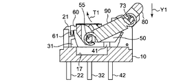
図9に示すように、操作レバー70が復帰位置にある状態では、摺動体50は、第1動作位置で保持され、第1固定接点21と共通固定接点41とを導通状態にしている。このとき、摺動体50には、反転ばね90の弾性力により、摺動体回動軸部56を中心に時計回りのトルクT1が働いている。
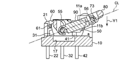
操作レバー70をY1方向に押圧し、図10に示す位置まで移動させると、摺動体50の摺動体回動軸部56と反転ばね90の軸心CLとが一直線上に並び、摺動体50に働いていたトルクT1が消滅する。そして、操作レバー70をY1方向にさらに押圧し、操作レバー70が図10に示す位置よりも下側に押し下げられた瞬間に、摺動体50に反時計回りのトルクT2が働く。すなわち、摺動体50に働くトルク方向が時計回りから反時計回りに反転し、スナップアクション動作する。
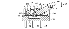
摺動体50にトルクT2が働くと、摺動体50は、反転ばね90の弾性によりベース10に近づく方向に付勢され、摺動体50が、摺動体回動軸部56を中心に反時計回りに回動し始める。そして、図11に示すように、摺動体50は、支持部11の水平部の下面11aに連続する鉛直部の側面11bにより画定される第2動作位置まで回動し、停止する。
なお、第2動作位置とは、第1可動接点61が第2固定接点31に接触すると共に、第2可動接点62が共通固定接点41に接触し、第2固定接点31と共通固定接点41とを相互に導通状態にする摺動体50の位置をいう。
このとき、可動接触片60の第1可動接点61は、第1,第2固定接点21,31からなる板状体を挟持したまま、この板状体の表面上をY1方向にスライド移動し、第2可動接点62は、共通固定接点41を挟持したまま、共通固定接点41の表面上をY1方向にスライド移動する。すなわち、摺動体50の回動により、第1固定接点21に接触していた第1可動接点61は、第1固定接点21から絶縁部33を介して第2固定接点31に摺動し、第2可動接点62は、共通固定接点41の表面上を摺動する。
その後、操作レバー70は、図12に示す位置まで押し下げられて、ベース10の支持部11と接触し、停止する。
操作レバー70への押圧を解除すると、操作レバー70は、復帰ばね91の弾性力によって、図13に示すY2方向に押し戻され、図14に示す復帰位置に復帰する。操作レバー70への押圧を解除することによって、操作レバー70を図12に示す位置から図13に示す位置まで移動させると、摺動体50の摺動体回動軸部56と反転ばね90の軸心CLとが一直線上に並び、摺動体50に働いていたトルクT2が消滅する。そして、操作レバー70が図13に示す位置よりも上側に押し戻された瞬間に、摺動体50に時計回りのトルクT1が働き、摺動体50に働くトルク方向が反時計回りから時計回りに反転し、スナップアクション動作する。
このように、ベース10に回動可能に支持された摺動体50および操作レバー70を反転ばね90で連結し、操作レバー70が所定の位置まで回動したときに反転ばね90の弾性力で摺動体50が回動し、第1可動接点61と第1,第2固定接点21,31とを接触または開離させる。すなわち、操作レバー70に加えられた外力により、導通経路が直接切り替えられるので、外力を操作レバー70に伝えるためにアクチュエータ等の部品を必要としない。このため、スイッチ100の部品点数および組立工数を低減し、その生産性を高めることができる。
また、前記スイッチ100では、摺動体50が、操作レバー70を所定の位置まで回動させたときに反転ばね90の弾性力によるスナップアクション動作により回動し、第1可動接点61と第1,第2固定接点21,31とを接触または開離させるように第1可動接点61をスライド移動させると共に、共通固定接点41に接触した状態を維持したまま第2可動接点62をスライド移動させる。このため、第1,第2可動接点61,62および各固定接点21,31,41の表面上に生成された不純物等が擦り取られ、ワイピング効果を得ることができ、接触信頼性を向上できる。
また、スイッチ部SW1,SW2の切り替えの際、摺動体50の回動によって、第2可動接点62が共通固定接点41に接触した状態のままスライド移動する。このため、3以上のスイッチ部を有していたとしても、全てのスイッチ部を略同時に切り替えることができる。
なお、前記スイッチ100では、摺動体50および操作レバー70が異なる回動支点を有している。すなわち、操作レバー70の回動支点となる操作レバー回動軸部74が、摺動体50の回動支点となる摺動体回動軸部56の上部に設けられている。このため、摺動体50および操作レバー70の回動支点が同じ位置にあるスイッチと比較して、摺動体50を回動させるために必要な操作レバー70のY1方向の押圧力を低減できる。すなわち、小さな操作レバー70に対する押圧力で、大きな摺動体50に対する駆動力を得ることができる。その結果、スイッチ部を3組以上設けたとしても、スイッチ部を容易に切り替えることができる。
また、前記スイッチ100では、支持部11の水平部の下面11aと、この下面11aに連続する鉛直部の側面11bとによって、摺動体50の回動範囲を画定している。このため、スイッチ部SW1,SW2の切り替えることによって回動した摺動体50は、摺動体50の回動支点となる摺動体回動軸部56の近傍に位置している支持部11の水平部および鉛直部に衝突して停止する。このように、支持部11の水平部および鉛直部を摺動体50の回動支点となる摺動体回動軸部56の近傍に配置しているため、摺動体50が回動したときに低い衝突速度で支持部11の水平部および鉛直部に衝突する。このため、摺動体50が支持部11の水平部および鉛直部に衝突することによる騒音を低減できる。
(その他の実施形態)
スイッチ部は、2組に限らず、図15に示すように、1組(SW1)であってもよいし、図16に示すように、3組(SW1~SW3)であってもよいし、図示していないが、4組以上であってもよい。また、スイッチ部は、一列に配置されている場合に限らず、固定接点が一直線上に並ばないように配置してもよい。
スイッチ部は、2組に限らず、図15に示すように、1組(SW1)であってもよいし、図16に示すように、3組(SW1~SW3)であってもよいし、図示していないが、4組以上であってもよい。また、スイッチ部は、一列に配置されている場合に限らず、固定接点が一直線上に並ばないように配置してもよい。
前記スイッチ100では、摺動体50と操作レバー70とを反転ばね90によって連結し、操作レバー70に加えられた外力により、導通経路を直接切り替えているが、これに限らない。すなわち、本発明は、摺動体の回動により、開閉用可動接点と少なくとも1つの開閉用固定接点とが接触または開離するように開閉用可動接点がスライド移動すると共に、共通可動接点が共通固定接点に接触した状態を維持しつつスライド移動するものであれば、任意の構成のスイッチに適用できる。
スイッチの組み立て方法は、前記実施形態に限らない。ベース、摺動体および操作レバーを組み付けた状態で、反転ばねを取り付ければよく、ベース、摺動体および操作レバーは、任意の順序で組み立てることができる。
ベース10の回動受部13に金属材料をインサートしてもよい。これにより、回動受部13の強度を高めることができる。また、回動受部13の代わりに、軸受構造を用いてもよい。
第1,第2固定接点21,31で構成された板状体および共通固定接点41は、摺動体50の回動により、第1,第2可動接点61,62が接触した状態でスライド移動可能な大きさおよび形状であればよく、任意の大きさおよび形状を採用することができる。
摺動体50は、可動接触片を挿入する摺動体貫通孔、摺動体回動軸部、および、反転ばねの一端を固定する取付軸部を一体に形成してもよいし、それぞれ別々に形成し、接着剤等で連結することにより摺動体を形成してもよい。また、反転ばね90の一端を固定する取付軸部55を金属材料で形成してもよい。これにより、取付軸部55の強度を高めることができる。
可動接触片60は、摺動体50の摺動体貫通孔53に挿入部63を挿入することにより固定されているが、これに限らない。例えば、可動接触片60は、インサート成形により摺動体50と一体に形成してもよいし、熱カシメにより摺動体50に固定してもよい。これにより、摺動体50に対する可動接触片60の固定強度を高めることができる。
操作レバー70は、操作部材およびレバー支持部を一体に形成してもよいし、それぞれ別々に形成し、接着剤等で連結することにより操作レバーを形成してもよい。また、反転ばね90の一端を固定する取付軸部73を金属材料で形成してもよい。これにより、取付軸部73の強度を高めることができる。
なお、操作体は、操作レバー70に限らず、摺動体50を回動させることができるものであればよく、その形状、大きさ、および、部品点数等は、スイッチの設計等に応じて任意に設定できる。例えば、操作体は、回動可能に支持されているものに限らず、直線的に移動可能に支持されているものでもよい。また、操作部と回動部とが一体に形成された操作レバー70に限らず、操作部と回動部とをそれぞれ別々に形成して連結したものでもよいし、操作部を複数の部品、例えば、回動部に外力を伝えるアクチュエータと、このアクチュエータを操作するための操作部材とで構成したものでもよい。
反転ばね90は、スイッチ100の設計に応じた弾性力を発揮するものであれば、任意の材料を用いることができる。また、コイルばねに限らず、板ばね、トーションばね、あるいは、ゴム等を採用することもできる。
復帰ばね91は、操作レバー70を押し下げたときに、反転ばね90の弾性力に抗って、操作レバー70を復帰位置に復帰させる弾性力を発揮するものであれば、任意の材料を用いることができる。また、トーションばねに限らず、コイルばね、あるいは、板ばね等を採用することもできる。
ベース10に摺動体50および操作レバー70を仮止めするための仮止め機構は、ベース10に摺動体50および操作レバー70を取り付けた状態で仮止めできるものであればよく、前記実施形態の構成に限らない。例えば、ベースに凸部を設け、摺動体に凸部に嵌合可能な凹部を設けてもよい。また、ベースに凹部を設け、操作レバーに凹部に嵌合可能な凸部を設けてもよい。
前記実施形態で述べた構成要素は、適宜、組み合わせてもよく、また、適宜、選択、置換、あるいは、削除してもよいことは、勿論である。
本発明のスイッチは、例えば、自動車の電子制御パーキングブレーキ等に利用できる。
10 ベース
11 支持部
12 切欠部
13 回動受部
14 摺動体取付孔
15 ベース突起
16 ばね取付孔
17 凹部
18 取付突部
20 第1固定接点端子
21 第1固定接点
22 第1固定端子
30 第2固定接点端子
31 第2固定接点
32 第2固定端子
40 共通固定接点端子
41 共通固定接点
42 共通固定端子
50 摺動体
51 本体部
52 腕部
53 摺動体貫通孔
54 突出部
55 取付軸部
56 摺動体回動軸部
57 摺動体突起
60 可動接触片
61 第1可動接点
62 第2可動接点
63 挿入部
64 係止爪部
65 弾性腕部
66 係止爪部
67 突起
70 操作レバー
71 操作部材
72 レバー支持部
73 取付軸部
74 操作レバー回動軸部
75 仮止め孔
76 段部
77 操作レバー貫通孔
80 カバー
81 カバー取付孔
82 支持孔
83 操作開口
90 反転ばね
91 復帰ばね
100 スイッチ
161 可動接点
11 支持部
12 切欠部
13 回動受部
14 摺動体取付孔
15 ベース突起
16 ばね取付孔
17 凹部
18 取付突部
20 第1固定接点端子
21 第1固定接点
22 第1固定端子
30 第2固定接点端子
31 第2固定接点
32 第2固定端子
40 共通固定接点端子
41 共通固定接点
42 共通固定端子
50 摺動体
51 本体部
52 腕部
53 摺動体貫通孔
54 突出部
55 取付軸部
56 摺動体回動軸部
57 摺動体突起
60 可動接触片
61 第1可動接点
62 第2可動接点
63 挿入部
64 係止爪部
65 弾性腕部
66 係止爪部
67 突起
70 操作レバー
71 操作部材
72 レバー支持部
73 取付軸部
74 操作レバー回動軸部
75 仮止め孔
76 段部
77 操作レバー貫通孔
80 カバー
81 カバー取付孔
82 支持孔
83 操作開口
90 反転ばね
91 復帰ばね
100 スイッチ
161 可動接点
Claims (3)
- ベースと、
互いに所定の間隔を空けて配置された、共通固定接点および少なくとも1つの開閉用固定接点を有し、前記ベースに設けられた少なくとも1つのスイッチ部と、
前記共通固定接点に摺動可能に接触する共通可動接点と、前記共通可動接点に導通し、かつ、前記開閉用固定接点に摺動可能に接触または開離する開閉用可動接点とを有し、前記ベースに回動可能に支持された摺動体と、
前記スイッチ部および前記摺動体を覆うように前記ベースに取り付けられたカバーと、
前記ベースまたは前記カバーに移動可能に支持された操作体と、
前記摺動体と前記操作体とを互いに近づく方向に付勢する弾性体と、
を備え、
前記摺動体は、前記操作体を所定の位置まで移動させたときに前記弾性体の弾性力によるスナップアクション動作により回動するように支持されており、
前記開閉用可動接点は、前記摺動体の回動に伴い、前記開閉用固定接点と接触または開離するようにスライド移動し、
前記共通可動接点は、前記摺動体の回動に伴い、前記共通固定接点に接触した状態を維持したままスライド移動する、スイッチ。 - 前記操作体が、前記ベースまたは前記カバーに回動可能に支持された回動部と、この回動部に連結された操作部とを有し、
前記摺動体および前記回動部が、異なる回動支点を有するように配置されている、請求項1に記載のスイッチ。 - 前記摺動体が、一対の前記開閉用可動接点と一対の前記共通可動接点とが設けられた可動接触片を有し、
前記一対の開閉用可動接点および前記一対の共通可動接点の各々が、前記摺動体の回動軸方向に取り付けられ、かつ、移動可能に取り付けられると共に、前記開閉用固定接点および前記共通固定接点を弾性挟持している、請求項1または2に記載のスイッチ。
Priority Applications (3)
| Application Number | Priority Date | Filing Date | Title |
|---|---|---|---|
| DE112015006204.1T DE112015006204T5 (de) | 2015-02-23 | 2015-08-13 | Schalter |
| US15/544,558 US20170372851A1 (en) | 2015-02-23 | 2015-08-13 | Switch |
| CN201580073465.2A CN107112158A (zh) | 2015-02-23 | 2015-08-13 | 开关 |
Applications Claiming Priority (2)
| Application Number | Priority Date | Filing Date | Title |
|---|---|---|---|
| JP2015033327A JP5954450B1 (ja) | 2015-02-23 | 2015-02-23 | スイッチ |
| JP2015-033327 | 2015-02-23 |
Publications (1)
| Publication Number | Publication Date |
|---|---|
| WO2016136002A1 true WO2016136002A1 (ja) | 2016-09-01 |
Family
ID=56418729
Family Applications (1)
| Application Number | Title | Priority Date | Filing Date |
|---|---|---|---|
| PCT/JP2015/072906 Ceased WO2016136002A1 (ja) | 2015-02-23 | 2015-08-13 | スイッチ |
Country Status (5)
| Country | Link |
|---|---|
| US (1) | US20170372851A1 (ja) |
| JP (1) | JP5954450B1 (ja) |
| CN (1) | CN107112158A (ja) |
| DE (1) | DE112015006204T5 (ja) |
| WO (1) | WO2016136002A1 (ja) |
Families Citing this family (4)
| Publication number | Priority date | Publication date | Assignee | Title |
|---|---|---|---|---|
| EP3813088B1 (en) * | 2018-05-29 | 2023-01-18 | Alps Alpine Co., Ltd. | Switch device |
| TWI698895B (zh) | 2018-11-16 | 2020-07-11 | 台灣華傑股份有限公司 | 導通切換機構 |
| JP7420636B2 (ja) * | 2020-04-17 | 2024-01-23 | 株式会社東海理化電機製作所 | スイッチ装置 |
| CN115917690A (zh) * | 2020-06-24 | 2023-04-04 | 阿尔卑斯阿尔派株式会社 | 切换开关 |
Citations (2)
| Publication number | Priority date | Publication date | Assignee | Title |
|---|---|---|---|---|
| JPS4877375A (ja) * | 1972-01-03 | 1973-10-17 | ||
| JP2003272482A (ja) * | 2002-03-18 | 2003-09-26 | Alps Electric Co Ltd | スイッチ |
Family Cites Families (4)
| Publication number | Priority date | Publication date | Assignee | Title |
|---|---|---|---|---|
| CN2143813Y (zh) * | 1992-12-19 | 1993-10-13 | 陈文宗 | 微动开关 |
| US5568860A (en) * | 1994-06-23 | 1996-10-29 | Methode Electronics, Inc. | Pivot point contact with scrubbing action switch |
| CN2333079Y (zh) * | 1998-06-30 | 1999-08-11 | 厦门市富亚电子有限公司 | 一种小型微动开关 |
| EP1764813B1 (de) * | 2005-09-16 | 2009-07-22 | ZF Friedrichshafen AG | Elektrischer Schalter |
-
2015
- 2015-02-23 JP JP2015033327A patent/JP5954450B1/ja active Active
- 2015-08-13 CN CN201580073465.2A patent/CN107112158A/zh active Pending
- 2015-08-13 WO PCT/JP2015/072906 patent/WO2016136002A1/ja not_active Ceased
- 2015-08-13 US US15/544,558 patent/US20170372851A1/en not_active Abandoned
- 2015-08-13 DE DE112015006204.1T patent/DE112015006204T5/de not_active Withdrawn
Patent Citations (2)
| Publication number | Priority date | Publication date | Assignee | Title |
|---|---|---|---|---|
| JPS4877375A (ja) * | 1972-01-03 | 1973-10-17 | ||
| JP2003272482A (ja) * | 2002-03-18 | 2003-09-26 | Alps Electric Co Ltd | スイッチ |
Also Published As
| Publication number | Publication date |
|---|---|
| US20170372851A1 (en) | 2017-12-28 |
| DE112015006204T5 (de) | 2017-11-02 |
| JP2016157537A (ja) | 2016-09-01 |
| JP5954450B1 (ja) | 2016-07-20 |
| CN107112158A (zh) | 2017-08-29 |
Similar Documents
| Publication | Publication Date | Title |
|---|---|---|
| JP4760998B1 (ja) | スイッチ | |
| JP5954450B1 (ja) | スイッチ | |
| JP5893753B2 (ja) | 自動車のステアリングコラムスイッチシステムのリセットデバイスおよび自動車 | |
| CN105378882A (zh) | 触点机构及使用其的触发开关、电动工具 | |
| JP6049079B2 (ja) | レバースイッチ | |
| CN103426676B (zh) | 多方向输入装置 | |
| JP5628715B2 (ja) | スイッチ装置 | |
| JP5614800B2 (ja) | スイッチ装置 | |
| JP5802078B2 (ja) | プッシュスイッチ | |
| JP6414483B2 (ja) | スイッチ | |
| CN101471197A (zh) | 开关装置 | |
| WO2013137203A1 (ja) | スイッチ | |
| JP4030735B2 (ja) | スイッチ装置 | |
| JP6388341B2 (ja) | スイッチおよびスイッチユニット | |
| JP5913700B1 (ja) | ダブルシーソースイッチ | |
| JP4853171B2 (ja) | スイッチ | |
| JP3187325U (ja) | 多方向入力装置 | |
| JPH0235141Y2 (ja) | ||
| CN109148190B (zh) | 用于按钮开关的驱动件及按钮开关 | |
| JP2016001565A (ja) | ケース付き機構装置 | |
| JP2003132752A (ja) | スイッチ接点構造 | |
| JP6160347B2 (ja) | スイッチ | |
| JP2012169229A (ja) | 入力操作装置 | |
| JPH05347114A (ja) | スイッチ装置の接点構造 | |
| NZ743435B2 (en) | Driving member for push-button switch and push-button switch |
Legal Events
| Date | Code | Title | Description |
|---|---|---|---|
| 121 | Ep: the epo has been informed by wipo that ep was designated in this application |
Ref document number: 15883292 Country of ref document: EP Kind code of ref document: A1 |
|
| WWE | Wipo information: entry into national phase |
Ref document number: 15544558 Country of ref document: US |
|
| WWE | Wipo information: entry into national phase |
Ref document number: 112015006204 Country of ref document: DE |
|
| 122 | Ep: pct application non-entry in european phase |
Ref document number: 15883292 Country of ref document: EP Kind code of ref document: A1 |