WO2016135781A1 - 鉄道車両 - Google Patents
鉄道車両 Download PDFInfo
- Publication number
- WO2016135781A1 WO2016135781A1 PCT/JP2015/001048 JP2015001048W WO2016135781A1 WO 2016135781 A1 WO2016135781 A1 WO 2016135781A1 JP 2015001048 W JP2015001048 W JP 2015001048W WO 2016135781 A1 WO2016135781 A1 WO 2016135781A1
- Authority
- WO
- WIPO (PCT)
- Prior art keywords
- pair
- floor pan
- vehicle
- longitudinal direction
- beams
- Prior art date
- Legal status (The legal status is an assumption and is not a legal conclusion. Google has not performed a legal analysis and makes no representation as to the accuracy of the status listed.)
- Ceased
Links
Images




Classifications
-
- B—PERFORMING OPERATIONS; TRANSPORTING
- B61—RAILWAYS
- B61F—RAIL VEHICLE SUSPENSIONS, e.g. UNDERFRAMES, BOGIES OR ARRANGEMENTS OF WHEEL AXLES; RAIL VEHICLES FOR USE ON TRACKS OF DIFFERENT WIDTH; PREVENTING DERAILING OF RAIL VEHICLES; WHEEL GUARDS, OBSTRUCTION REMOVERS OR THE LIKE FOR RAIL VEHICLES
- B61F1/00—Underframes
- B61F1/08—Details
-
- B—PERFORMING OPERATIONS; TRANSPORTING
- B61—RAILWAYS
- B61F—RAIL VEHICLE SUSPENSIONS, e.g. UNDERFRAMES, BOGIES OR ARRANGEMENTS OF WHEEL AXLES; RAIL VEHICLES FOR USE ON TRACKS OF DIFFERENT WIDTH; PREVENTING DERAILING OF RAIL VEHICLES; WHEEL GUARDS, OBSTRUCTION REMOVERS OR THE LIKE FOR RAIL VEHICLES
- B61F1/00—Underframes
- B61F1/08—Details
- B61F1/14—Attaching or supporting vehicle body-structure
-
- B—PERFORMING OPERATIONS; TRANSPORTING
- B61—RAILWAYS
- B61D—BODY DETAILS OR KINDS OF RAILWAY VEHICLES
- B61D17/00—Construction details of vehicle bodies
- B61D17/04—Construction details of vehicle bodies with bodies of metal; with composite, e.g. metal and wood body structures
- B61D17/10—Floors
-
- B—PERFORMING OPERATIONS; TRANSPORTING
- B61—RAILWAYS
- B61F—RAIL VEHICLE SUSPENSIONS, e.g. UNDERFRAMES, BOGIES OR ARRANGEMENTS OF WHEEL AXLES; RAIL VEHICLES FOR USE ON TRACKS OF DIFFERENT WIDTH; PREVENTING DERAILING OF RAIL VEHICLES; WHEEL GUARDS, OBSTRUCTION REMOVERS OR THE LIKE FOR RAIL VEHICLES
- B61F1/00—Underframes
- B61F1/08—Details
- B61F1/12—Cross bearers
-
- B—PERFORMING OPERATIONS; TRANSPORTING
- B60—VEHICLES IN GENERAL
- B60L—PROPULSION OF ELECTRICALLY-PROPELLED VEHICLES; SUPPLYING ELECTRIC POWER FOR AUXILIARY EQUIPMENT OF ELECTRICALLY-PROPELLED VEHICLES; ELECTRODYNAMIC BRAKE SYSTEMS FOR VEHICLES IN GENERAL; MAGNETIC SUSPENSION OR LEVITATION FOR VEHICLES; MONITORING OPERATING VARIABLES OF ELECTRICALLY-PROPELLED VEHICLES; ELECTRIC SAFETY DEVICES FOR ELECTRICALLY-PROPELLED VEHICLES
- B60L2200/00—Type of vehicles
- B60L2200/26—Rail vehicles
Definitions
- the present invention relates to a railway vehicle, and more particularly to a railway vehicle having a floor structure having a floor pan.
- the railway vehicle structure includes a frame, a pair of side structures provided on both sides of the frame in the vehicle width direction, a roof structure provided over each side structure, and a wife structure provided at both ends in the vehicle longitudinal direction.
- the underframe has a pair of side beams extending in the vehicle longitudinal direction and a plurality of horizontal beams extending in the vehicle width direction and connected to the pair of side beams.
- a floor pan (also referred to as a sub-floor pan) is provided in a region surrounded by a pair of side beams and a pair of adjacent horizontal beams, and a floor board is provided above the floor pan.
- a heat insulating material may be provided between the floor pan and the floor plate, for example, as disclosed in Patent Document 1.
- a railway vehicle structure is required to have a structural strength that can withstand, for example, a compressive load received from the vehicle end in the longitudinal direction of the vehicle and a torsional load received during jacking up or lifting by a crane during traveling or maintenance. .
- the strength of the structure may be increased by increasing the thickness of the side beams and the cross beams, or by increasing the number of members that reinforce the underframe, but doing so may increase the weight of the railway vehicle. .
- an object of the present invention is to increase the structural strength of a railway vehicle structure with a simple configuration while suppressing an increase in weight.
- a railway vehicle includes a pair of side beams and a plurality of horizontal beams that are connected to the pair of side beams and arranged at intervals in the vehicle longitudinal direction.
- a floor pan disposed in a region surrounded by a pair of side beams adjacent to each other among the pair of side beams and the plurality of lateral beams, and fixed to the underframe, the floor pan comprising:
- the strength member is configured to bear at least one of a compressive load and a shear load received from the frame.
- the floor pan is disposed and fixed to the underframe in the region surrounded by the pair of side beams adjacent to each other among the pair of side beams and the plurality of horizontal beams.
- the strength member is configured to bear at least one of a compressive load and a shear load to be received.
- the structural strength of the railway vehicle structure can be increased with a simple configuration while suppressing an increase in weight.
- FIG. 1 is a schematic side view of a railway vehicle according to an embodiment. It is a top view of the underframe looked down from the perpendicular direction. It is a disassembled perspective view which shows a part of underframe and a floor pan. It is a top view which shows a part of underframe and floor pan looked down from the perpendicular direction. It is the fragmentary sectional view of the floor pan seen from the vehicle longitudinal direction. It is the fragmentary sectional view of the floor pan seen from the vehicle width direction. It is the fragmentary sectional view seen from the vehicle longitudinal direction of the floor pan in which repair was performed. It is the fragmentary sectional view seen from the vehicle longitudinal direction of the floor pan in which opening was formed.
- FIG. 1 is a schematic side view of a railway vehicle 1 according to the embodiment.
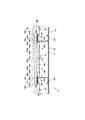
- FIG. 2 is a plan view of the underframe 3 as viewed from the vertical direction.
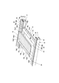
- FIG. 3 is an exploded perspective view showing a part of the underframe 3 and the floor pan 15.
- FIG. 4 is a plan view showing a part of the frame 3 and the floor pan 15 as viewed from the vertical direction. 3 and 4, only the floor pan 15 is shown for convenience.
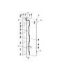
- FIG. 5 is a partial cross-sectional view of the floor pan 15 as seen from the vehicle longitudinal direction.
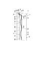
- FIG. 6 is a partial cross-sectional view of the floor pan 15 as seen from the vehicle width direction.
- the railway vehicle 1 includes a carriage 2 and a vehicle body (a railway vehicle structure) 7 supported by the carriage 2.
- the vehicle body 7 includes a frame 3, a side structure 4, a roof structure 5, and a wife structure 6.
- a pair of carriages 2 are arranged at positions separated in the longitudinal direction of the vehicle.
- the side structure 4 is arrange
- the roof structure 5 is disposed above each side structure 4 and connected to each side structure 4.
- the wife structures 6 are disposed on both sides of the frame 3 in the longitudinal direction of the vehicle.
- the underframe 3 includes a side beam 10, an end beam 11, a middle beam 12, a pillow beam 13, a lateral beam 14, and a floor pan 15.
- a pair of side beams 10 are arranged in the vehicle longitudinal direction and spaced apart in the vehicle width direction.
- the side beam 10 is combined with the first plate member 16 having a substantially L-shaped cross section when viewed from the vehicle longitudinal direction and the second plate member having a substantially W-shaped cross section when viewed from the vehicle longitudinal direction. 17 and an upper surface 18 a that protrudes inward in the vehicle width direction of the underframe 3 in the horizontal direction and has a third plate member 18 connected to the second plate member 17.
- Each of the first plate member 16, the second plate member 17, and the third plate member 18 extends in the vehicle longitudinal direction.
- a hollow structure is formed in the side beam 10 by combining the second plate member 17 with the first plate member 16 so as to form an internal space with the first plate member 16.
- a support member 19 that reinforces the side beam 10 and supports a floor plate 30 described later is provided on the upper surface 18 a of the third plate member 18.
- the support member 19 extends in the longitudinal direction of the vehicle and has a hat-shaped cross section when viewed from the longitudinal direction of the vehicle.
- the support member 19 has a main body portion 19b that has a convex upper surface and a flat upper surface when viewed from the longitudinal direction of the vehicle, and a third plate member that protrudes in opposite directions from the lower end of the main body portion 19b. 18 and a pair of flange portions 19a fixed to the upper surface 18a.
- a floor board 30 is disposed above the support member 19.
- the support member 19 supports the floor board 30 (see FIGS. 5 and 6) from below on the flat upper surface of the main body 19b.
- the end beam 11 extends in the vehicle width direction and is connected to each end portion of the pair of side beams 10 in the vehicle longitudinal direction.
- the pair of pillow beams 13 extend in the vehicle width direction, are disposed in pairs in the vehicle longitudinal direction of the railway vehicle 1 with respect to the end beams 11, and are connected to the pair of side beams 10.
- the carriage 2 is connected to the lower part of each pillow beam 13. Thereby, the load from the vehicle body 7 is transmitted to the carriage 2.
- the intermediate beam 12 extends in the longitudinal direction of the vehicle, is disposed between the end beam 11 and the pillow beam 13, and is connected to the end beam 11 and the pillow beam 13.
- the horizontal beam 14 is a member that extends in the vehicle width direction and connects the pair of side beams 10 and is disposed between a pair of pillow beams 13 that are adjacent in the vehicle longitudinal direction.
- the cross beam 14 has a C-shaped cross section when viewed from the vehicle width direction (see FIG. 6).
- the horizontal beam 14 includes an upper plate portion 14a extending in the horizontal direction, a lower plate portion 14c extending downward in the horizontal direction from the upper plate portion 14a, and one end of the upper plate portion 14a in the vehicle longitudinal direction and the lower plate portion 14c. And a side plate portion 14b connected to one end in the longitudinal direction of the vehicle.
- a large number of cross beams 14 are arranged at intervals in the longitudinal direction of the vehicle. Thereby, a plurality of regions S1 surrounded by the pair of side beams 10 and the pair of adjacent lateral beams 14 are arranged in parallel in the vehicle longitudinal direction.
- the floor pan 15 extends in the vehicle width direction, is disposed in the region S1, and is fixed to the pair of side beams 10 and the pair of lateral beams 14.
- the floor pan 15 is disposed in a region S1 of the plurality of regions S1 that is located with one or more regions S1 from the pillow beams 13 inward in the vehicle longitudinal direction. That is, the floor pan 15 is not disposed in the region S1 closest to the pillow beam 13.
- the several floor pan 15 is arrange
- the floor pan 15 has a bathtub shape having a bottom wall portion 15a, a side wall portion 15b, and a flange portion 15c.
- the bottom wall portion 15 a is located below the upper surface 14 a 1 of the upper plate portion 14 a in the horizontal beam 14 and the upper surface 18 a of the third plate material 18 in the side beam 10.
- the bottom wall portion 15a has a rectangular outline in plan view, and has a long side extending in the vehicle width direction and a short side extending in the vehicle longitudinal direction. Further, the bottom wall portion 15a has a plurality of peak portions 15a1 arranged at intervals, and a flat portion 15a2 continuous so as to surround each of the plurality of peak portions 15a1.
- the mountain portion 15a1 is a bulging portion that bulges in the vertical direction (here, the upper side in the vertical direction).
- the mountain portion 15a1 has a base portion 15a3 extending in the longitudinal direction of the vehicle and end portions 15a4 formed at both ends in the longitudinal direction of the base portion 15a3.
- the plurality of peak portions 15a1 are juxtaposed in the vehicle width direction at intervals.
- the contour shape of the end portion 15a4 is a curved shape that is convex outward in the longitudinal direction of the vehicle (the vehicle longitudinal direction), and specifically, an arc shape.
- the mountain portion 15a1 when viewed from the longitudinal direction of the vehicle, has a curved shape whose contour shape is convex upward, specifically, an arc shape.
- the plurality of peak portions 15a1 are formed in a gentle wave shape across the flat portion 15a2.
- the contour shape of the mountain portion 15a1 when viewed from the vehicle width direction, includes a straight portion 15a5 and a pair of curved portions 15a6.
- the straight portion 15a5 is spaced apart from the flat portion 15a2 and extends in the vehicle longitudinal direction.
- the pair of curved portions 15a6 are connected to both ends of the straight portion 15a5 in the vehicle longitudinal direction and the flat portion 15a2 in a curved shape.
- the curved portion 15a6 has a curved shape that is convex upward as viewed from the vehicle width direction, and specifically has an arc shape.
- the mountain portion 15a1 does not have a corner portion when viewed from the vehicle longitudinal direction or the vehicle width direction. Even when viewed from the vertical direction, the base portion 15a3 and the end portion 15a4 of the mountain portion 15a1 are connected at a gentle angle. For this reason, local stress concentration in the peak portion 15a1 is avoided.
- the bulging height h1 of the mountain portion 15a1 in the vertical direction is set to be lower than the side wall portion 15b.
- the side wall 15b1 on the side beam 14 side is lower than the side wall 15b2 on the side beam 10 side.
- the bulging height h1 of the peak portion 15a1 is set to a value that is not less than 10% and not more than 50% of the height h2 of the side wall portion 15b1 on the side beam 14 side.
- the width D1 in the vehicle width direction of the mountain portion 15a1 is set wider than the interval D2 between the mountain portions 15a1 in the vehicle width direction. More specifically, the width D1 is set to a value not less than 3 times and not more than 15 times the interval D2. By setting the width D1 in this way, it is possible to prevent the flat portion 15a2 from buckling when receiving a load. Further, the length L1 of the mountain portion 15a1 in the vehicle longitudinal direction is shorter than the length L2 of the bottom wall portion 15a in the vehicle longitudinal direction. As an example, the length L1 is set to a value not less than 70% and not more than 95% of the length L2. By setting the length L1 in this way, a space between the peak portion 15a1 and the side wall portion 15b is secured, and the floor pan 15 can be easily manufactured by pressing as described later.
- the flat portion 15a2 is formed so as to surround each mountain portion 15a1.
- the mountain parts 15a1 adjacent in the vehicle width direction are separated from each other via the flat part 15a2, and all the mountain parts 15a1 are separated from any side wall part 15b via the flat part 15a2.
- the apparent total area of the mountain portion 15a1 is set larger than the apparent total area of the flat portion 15a2.
- the “apparent area” means a projected area when the bottom wall portion 15a is viewed in plan from the vertical direction.
- the side wall 15b surrounds the periphery of the bottom wall 15a and extends upward from the periphery of the bottom wall 15a.
- the flange portion 15c is connected to the upper end of the side wall portion 15b.
- the flange portion 15c has a long side portion 15c1 extending in the vehicle width direction and a short side portion 15c2 extending in the vehicle longitudinal direction.
- the long side portion 15 c 1 is fixed to the upper surface 14 a 1 of the upper plate portion 14 a of the cross beam 14.
- the short side portion 15 c 2 is fixed to the upper surface 19 a 1 of the flange portion 19 a of the support member 19. Thereby, the short side part 15c2 is arrange
- the floor pan 15 is integrally formed by pressing a metal (for example, stainless steel) plate material.
- the thickness of the floor pan 15 is thinner than any of the first plate member 16, the second plate member 17, and the third plate member 18 in the side beam 10 and thinner than the thickness of the cross beam 14.
- the thickness of the floor pan 15 is preferably 0.6 mm or more and 1.2 mm or less, and 0.9 mm or more and 1.0 mm or less from the viewpoint of processability of the floor pan 15, ensuring structural strength and suppressing weight increase. The value of is more desirable.
- An end portion 15c3 of the long side portion 15c1 of the floor pan 15 is opposed to an end portion 15c3 of the long side portion 15c1 of another adjacent floor pan 15 on the upper surface 14a1 of the upper plate portion 14a of the cross beam 14 with a space therebetween ( (See FIG. 6).
- the long side portion 15c1 of the flange portion 15c is fixed to the upper plate portion 14a of the cross beam 14 by spot welding.
- the short side portion 15c2 of the flange portion 15c is fixed to the flange portion 19a of the support member 19 by spot welding.
- a heat insulating material (not shown) is disposed between the floor pan 15 and the floor board 30 and around the support member 19. Below the floor pan 15, a plurality of unshown floor devices (for example, high voltage devices such as a main transformer and a main converter) fixed to the vehicle body 7 are arranged.
- unshown floor devices for example, high voltage devices such as a main transformer and a main converter
- the bottom wall portion 15a of the floor pan 15 has a plurality of mountain portions 15a1 extending in the vehicle longitudinal direction and arranged in parallel in the vehicle width direction, and a flat portion 15a2 surrounding each mountain portion 15a1. Is formed. For this reason, the floor pan 15 is not easily deformed even if an external force is applied from any of the vertical direction, the vehicle longitudinal direction, and the vehicle width direction. Thereby, the floor pan 15 functions as a strength member that bears a compressive load and a shear load received from the pair of side beams 10 or the lateral beams 14. That is, the frame structure of the underframe 3 having the pair of side beams 10 and the plurality of lateral beams 14 in the vehicle body 7 is reinforced by the plurality of floor pans 15.
- the vehicle body 7 can be reinforced with a simple configuration, and the structural strength of the vehicle body 7 can be increased. Further, since the floor pan 15 firmly connects the pair of side beams 10 to each other, when a vehicle end compression load is applied, the floor pan 15 can increase the strength against lateral buckling of the underframe 3 or buckling of the side beams 10 alone. it can. Therefore, in order to increase the strength of the underframe 3, it is not necessary to increase the thickness of the side beams 10 and the lateral beams 14, or increase the number of reinforcing members that reinforce the underframe 3, and the weight of the vehicle body 7 increases. Can be suppressed.
- each floor pan 15 is prevented from being deformed against the compressive load by a plurality of peak portions 15a1 extending in the vehicle longitudinal direction. Is done. For this reason, the vehicle body 7 is reinforced to withstand this compressive load. Further, when a torsional load is applied to the vehicle body 7 due to traveling, jacking up during maintenance, lifting by a crane, or the like, and as a result, a shear load is applied to the underframe 3, each floor pan 15 is The plurality of peak portions 15a1 and the flat portion 15a2 prevent deformation so as to resist the shear load. For this reason, the vehicle body 7 is reinforced to withstand this torsional load.
- the contour shape of the mountain portion 15a1 is a curve when viewed from the vehicle longitudinal direction, local stress concentration in the mountain portion 15a1 is prevented when a load is applied to the vehicle body 7 from the vehicle width direction.
- the straight portion 15a5 of the mountain portion 15a1 and the pair of curved portions 15a6 are connected in a curved shape when viewed from the vehicle width direction, when a load is applied to the vehicle body 7 from the vehicle longitudinal direction, Local stress concentration at each connecting portion between the straight portion 15a5 of the portion 15a1 and the pair of curved portions 15a6 is prevented.
- the vehicle body 7 is in any one of the vehicle longitudinal direction and the vehicle width direction.
- a load is applied, local stress concentration at the connecting portion between the base portion 15a3 of the peak portion 15a1 and the pair of end portions 15a4 is prevented.
- the floor pan 15 can be appropriately prevented from being damaged or deformed by local stress concentration.
- the bottom wall portion 15a of the floor pan is formed with a mountain portion 15a1 and a flat portion 15a2, and the bottom wall portion 15a is formed by the upper surface portion 14a1 of the upper plate portion 14a of the lateral beam 14 and the third plate material 18 of the side beam 10. It is located below the upper surface 18a. For this reason, even when a load is applied to the flange portion 15c from the outside, the load is not easily transmitted to the bottom wall portion 15a. Therefore, it is possible to appropriately prevent the floor pan 15 from being damaged.
- the apparent total area of the mountain portion 15a1 is set to be larger than the apparent total area of the flat portion 15a2, so that the buckling strength of the flat portion 15a2 is increased.
- the function of the floor pan 15 as a strength member can be improved without increasing the thickness of the floor pan 15.
- the floor pan 15 is arranged in a region S1 that is located at one or more regions S1 from the pillow beam 13 inward in the longitudinal direction of the vehicle among the plurality of regions S1. This prevents an excessive compressive load from being directly applied to the floor pan 15 from the pillow beam 13 and secures the space above the carriage 2 (prevents interference between the carriage 2 and the floor pan 15).
- the vehicle body 7 is strengthened mainly in the longitudinal direction of the vehicle in the longitudinal direction, and the railway vehicle structure is effectively The structural strength of can be improved.
- the height of the cross beam 14 can be reduced by improving the strength of the frame 3, for example, the position of the upper surface 14a1 of the horizontal beam 14 is lowered while maintaining the position of the floor plate 30 in the vertical direction. By doing so, the space between the cross beam 14 and the floor board 30 can be ensured thick, and heat insulation performance can also be improved.
- FIG. 7 is a partial cross-sectional view of the floor pan 15 that has been repaired as seen from the longitudinal direction of the vehicle.
- a flat portion 15a2 is formed in the bottom wall portion 15a of the floor pan 15
- a hole H is generated in the bottom wall portion 15a of the floor pan 15 due to a stepping stone or the like.
- the lower portions 15a7 and 15a8 of the flat portion 15a2 located on both sides in the vehicle width direction of one mountain portion 15a1 are flattened so as to cover the problematic bottom wall portion 15a.
- the floor pan 15 can be repaired quickly by arranging the reinforcing plates 20 so as to overlap and fixing the reinforcing plates 20 to the lower portions 15a7 and 15a8 by spot welding, plug welding, rivets or the like. Moreover, the floor pan 15 can be reinforced also by forming a hollow structure by bonding the peak portion 15a1 and the reinforcing plate 20 together.
- FIG. 8 is a partial cross-sectional view of the floor pan 15 in which the opening 15d is formed as seen from the vehicle longitudinal direction.
- a wide flat portion 21 is formed below the peak portion 15a1. Therefore, using this flat portion 21, for example, an opening 20a is formed in the reinforcing plate 20 below the peak portion 15a1 of the floor pan 15, and a through tube 22 with the tube axis directed vertically is inserted through the opening 20a.
- the through pipe 22 can be fixed to the upper surface of the reinforcing plate 20 by welding or the like at the periphery of the opening 20a.
- the cable 23 can be passed through the through pipe 22 and passed over the floor pan 15 through an opening 15d formed in the peak portion 15a1 with a minimum size.
- the periphery of the opening 20a can be reinforced with the through pipe 22 while forming the opening 20a necessary for the reinforcing plate 20, and the degree of freedom in designing the railway vehicle 1 can be increased.
- the cable 23 can be protected from a stepping stone or the like by forming the hollow structure by bonding the peak portion 15a1 and the reinforcing plate 20 together.
- the floor pan 15 is a strength member that bears the compressive load and shear load received from the frame 3, but may be a strength member that bears at least one of the compressive load and shear load received from the frame 3. That's fine.
- the bulging portion (mountain portion 15a1) formed on the bottom wall portion 15a of the floor pan 15 is bulged upward in the vertical direction, but the bulging portion may be bulged downward in the vertical direction.
- the bottom wall portion 15a of the floor pan 15 is formed with a bulging portion (peak portion 15a1) bulging upward in the vertical direction and a bulging portion (valley portion) bulging downward in the vertical direction. May be.
- a heat insulating material may not necessarily be provided between the floor pan 15 and the floor board 30 and around the support member 19.
- An air layer may be provided between the floor pan 15 and the floor board 30 and around the support member 19.
- the method of welding the floor pan 15 to the side beams 10 and the cross beams 14 is not limited to the spot welding method, but may be other welding methods such as a laser welding method.
- the long side portions 15c1 of the floor pans 15 adjacent in the vehicle longitudinal direction may partially overlap each other.
Landscapes
- Engineering & Computer Science (AREA)
- Mechanical Engineering (AREA)
- Life Sciences & Earth Sciences (AREA)
- Wood Science & Technology (AREA)
- Body Structure For Vehicles (AREA)
- Laminated Bodies (AREA)
Abstract
Description
2 台車
3 台枠
10 側梁
13 枕梁
14 横梁
14a1 横梁の上面(上板部の上面)
15 フロアパン
15a 底壁部
15a1 山部(膨出部)
15a2 平坦部
15a4 端部
15a5 直線部
15a6 曲線部
15b 側壁部
15c フランジ部
18a 第3板材の上面(側梁の上面)
Claims (10)
- 一対の側梁と、前記一対の側梁に接続されて車両長手方向で間隔をおいて配置された複数の横梁とを有する台枠と、
前記一対の側梁と前記複数の横梁のうちで隣接する一対の横梁とで囲まれた領域に配置され、前記台枠に固定されたフロアパンと、を備え、
前記フロアパンが、前記台枠から受ける圧縮荷重及びせん断荷重の少なくともいずれかを負担する強度部材として構成されている、鉄道車両。 - 前記フロアパンの底壁部は、鉛直方向に膨出する1以上の膨出部と、前記膨出部の周囲を囲む平坦部とを有する、請求項1に記載の鉄道車両。
- 車両長手方向から見て、前記膨出部の輪郭形状が、曲線状である、請求項2に記載の鉄道車両。
- 車幅方向から見て、前記膨出部の輪郭形状が、前記平坦部と離間して車両長手方向に延びる直線部と、前記直線部の車両長手方向の両端部と前記平坦部とにそれぞれ曲線状に接続された一対の曲線部とからなる形状である、請求項2または3に記載の鉄道車両。
- 鉛直方向から見て、前記膨出部の車両長手方向の両端部の各輪郭形状が、曲線状である、請求項2~4のいずれか1項に記載の鉄道車両。
- 鉛直方向から見て、前記膨出部の見掛けの総面積が、前記平坦部の見掛けの総面積よりも大きい、請求項2~5のいずれか1項に記載の鉄道車両。
- 前記フロアパンの底壁部において、複数の前記膨出部が、車幅方向に並設されている、請求項2~6のいずれか1項に記載の鉄道車両。
- 前記フロアパンの底壁部において、複数の前記膨出部が、車両長手方向に延びている、請求項7に記載の鉄道車両。
- 前記フロアパンは、その底壁部の周縁から上方に延びる側壁部と、前記側壁部の上端に接続されたフランジ部とを有し、前記フランジ部が前記台枠に固定され、
前記フロアパンの底壁部が、前記横梁の上面及び前記側梁の上面よりも下方に位置している、請求項1~8のいずれか1項に記載の鉄道車両。 - 前記台枠は、一対の台車に支持される一対の枕梁をさらに有し、
前記複数の横梁は、前記一対の枕梁の間に配置され、
前記台枠には、前記一対の側梁と前記一対の横梁とで囲まれた領域が車両長手方向に複数並設されており、
前記フロアパンは、前記複数の領域のうち、前記枕梁から車両長手方向の内方に向けて1以上の領域をおいて位置する領域に配置されている、請求項1~9のいずれか1項に記載の鉄道車両。
Priority Applications (6)
| Application Number | Priority Date | Filing Date | Title |
|---|---|---|---|
| SG11201705903RA SG11201705903RA (en) | 2015-02-27 | 2015-02-27 | Railcar |
| JP2017501547A JP6454777B2 (ja) | 2015-02-27 | 2015-02-27 | 鉄道車両 |
| US15/552,374 US10549765B2 (en) | 2015-02-27 | 2015-02-27 | Railcar |
| CN201580076666.8A CN107249960B (zh) | 2015-02-27 | 2015-02-27 | 铁道车辆 |
| PCT/JP2015/001048 WO2016135781A1 (ja) | 2015-02-27 | 2015-02-27 | 鉄道車両 |
| TW104117758A TWI565614B (zh) | 2015-02-27 | 2015-06-02 | Railway vehicles |
Applications Claiming Priority (1)
| Application Number | Priority Date | Filing Date | Title |
|---|---|---|---|
| PCT/JP2015/001048 WO2016135781A1 (ja) | 2015-02-27 | 2015-02-27 | 鉄道車両 |
Publications (1)
| Publication Number | Publication Date |
|---|---|
| WO2016135781A1 true WO2016135781A1 (ja) | 2016-09-01 |
Family
ID=56789267
Family Applications (1)
| Application Number | Title | Priority Date | Filing Date |
|---|---|---|---|
| PCT/JP2015/001048 Ceased WO2016135781A1 (ja) | 2015-02-27 | 2015-02-27 | 鉄道車両 |
Country Status (6)
| Country | Link |
|---|---|
| US (1) | US10549765B2 (ja) |
| JP (1) | JP6454777B2 (ja) |
| CN (1) | CN107249960B (ja) |
| SG (1) | SG11201705903RA (ja) |
| TW (1) | TWI565614B (ja) |
| WO (1) | WO2016135781A1 (ja) |
Families Citing this family (9)
| Publication number | Priority date | Publication date | Assignee | Title |
|---|---|---|---|---|
| US10549764B2 (en) * | 2015-02-27 | 2020-02-04 | Kawasaki Jukogyo Kabushiki Kaisha | Attaching metal fitting, attaching unit, and railcar |
| WO2016151613A1 (ja) * | 2015-03-20 | 2016-09-29 | 川崎重工業株式会社 | 鉄道車両 |
| CA2967235C (en) | 2015-08-31 | 2019-03-26 | Nippon Sharyo, Ltd. | Railcar |
| JP6359170B2 (ja) | 2015-08-31 | 2018-07-18 | 日本車輌製造株式会社 | 鉄道車両 |
| AT519330B1 (de) * | 2016-10-27 | 2022-04-15 | Siemens Mobility Austria Gmbh | Langträgeranordnung für einen Wagenkasten eines Fahrzeugs |
| CN108928358B (zh) * | 2018-07-09 | 2020-02-14 | 中车青岛四方机车车辆股份有限公司 | 底架结构及具有其的列车 |
| CN108928359B (zh) * | 2018-07-09 | 2020-06-16 | 中车青岛四方机车车辆股份有限公司 | 底架结构及具有其的列车 |
| AT523461B1 (de) * | 2020-02-06 | 2022-02-15 | Voestalpine Stahl Gmbh | Untergestell für Plattformwagen sowie Plattformwagen |
| RU204955U1 (ru) * | 2021-02-26 | 2021-06-21 | Акционерное общество "Рузаевский завод химического машиностроения" (АО "Рузхиммаш") | Рама грузового вагона |
Citations (3)
| Publication number | Priority date | Publication date | Assignee | Title |
|---|---|---|---|---|
| JPS5751566A (en) * | 1980-08-04 | 1982-03-26 | Budd Co | Wiring pipe for mounting under floor of railway rolling stock |
| CN102167051A (zh) * | 2011-03-07 | 2011-08-31 | 南车长江车辆有限公司 | 铁路浴盆敞车底架 |
| WO2013150736A1 (ja) * | 2012-04-02 | 2013-10-10 | 川崎重工業株式会社 | 鉄道車両 |
Family Cites Families (16)
| Publication number | Priority date | Publication date | Assignee | Title |
|---|---|---|---|---|
| GB543612A (en) * | 1939-09-22 | 1942-03-05 | Budd Edward G Mfg Co | Improvements in or relating to rail car underframes |
| US4074495A (en) * | 1975-05-27 | 1978-02-21 | Bodnar Ernest R | Sheet metal panel |
| JPH01229762A (ja) * | 1988-03-11 | 1989-09-13 | Hitachi Ltd | 鉄道車両構体のトラス台枠構造 |
| DE9106253U1 (de) * | 1991-05-21 | 1991-08-08 | Karl Glumann Maschinenbau, O-9034 Chemnitz | Schienengerätewagen in Baukastenaufbau |
| JPH05254429A (ja) | 1992-03-13 | 1993-10-05 | Tokyu Car Corp | 鉄道車両用台枠 |
| JP2638391B2 (ja) * | 1992-06-19 | 1997-08-06 | 株式会社日立製作所 | 鉄道車両の車体 |
| JPH0645884U (ja) | 1992-11-30 | 1994-06-21 | 日本車輌製造株式会社 | 車両の床構造 |
| ATE152980T1 (de) * | 1993-02-24 | 1997-05-15 | Siemens Sgp Verkehrstech Gmbh | Einrichtung zum schutz für passagiere gegen verletzungen bei einem zusammenstoss von eisenbahnzügen |
| CN2590961Y (zh) * | 2002-12-16 | 2003-12-10 | 青岛马士基集装箱工业有限公司 | 集装箱外侧波纹板 |
| CN101254849B (zh) * | 2007-03-02 | 2010-05-26 | 中国国际海运集装箱(集团)股份有限公司 | 集装箱门端结构 |
| PL2130739T3 (pl) * | 2008-06-06 | 2014-02-28 | Bombardier Transp Gmbh | Zespół ostoi wagonu kolejowego i modułowy korpus wagonu dla pojazdu szynowego |
| CN201309700Y (zh) * | 2008-07-11 | 2009-09-16 | 胜狮货柜技术研发(上海)有限公司 | 集装箱 |
| CN201580395U (zh) * | 2009-10-30 | 2010-09-15 | 青岛四方庞巴迪铁路运输设备有限公司 | 轨道车辆不锈钢车体底架结构 |
| JP5684539B2 (ja) | 2010-11-09 | 2015-03-11 | 日本車輌製造株式会社 | 鉄道車両の床構造 |
| CN103625484B (zh) * | 2012-08-21 | 2016-04-20 | 中车青岛四方机车车辆股份有限公司 | 大轴重发电车车体钢结构 |
| CN203005435U (zh) * | 2012-12-20 | 2013-06-19 | 哈尔滨轨道交通装备有限责任公司 | 平车地板 |
-
2015
- 2015-02-27 CN CN201580076666.8A patent/CN107249960B/zh active Active
- 2015-02-27 WO PCT/JP2015/001048 patent/WO2016135781A1/ja not_active Ceased
- 2015-02-27 SG SG11201705903RA patent/SG11201705903RA/en unknown
- 2015-02-27 JP JP2017501547A patent/JP6454777B2/ja active Active
- 2015-02-27 US US15/552,374 patent/US10549765B2/en active Active
- 2015-06-02 TW TW104117758A patent/TWI565614B/zh active
Patent Citations (3)
| Publication number | Priority date | Publication date | Assignee | Title |
|---|---|---|---|---|
| JPS5751566A (en) * | 1980-08-04 | 1982-03-26 | Budd Co | Wiring pipe for mounting under floor of railway rolling stock |
| CN102167051A (zh) * | 2011-03-07 | 2011-08-31 | 南车长江车辆有限公司 | 铁路浴盆敞车底架 |
| WO2013150736A1 (ja) * | 2012-04-02 | 2013-10-10 | 川崎重工業株式会社 | 鉄道車両 |
Also Published As
| Publication number | Publication date |
|---|---|
| JPWO2016135781A1 (ja) | 2017-08-17 |
| CN107249960B (zh) | 2019-08-30 |
| TWI565614B (zh) | 2017-01-11 |
| US20180037238A1 (en) | 2018-02-08 |
| CN107249960A (zh) | 2017-10-13 |
| US10549765B2 (en) | 2020-02-04 |
| JP6454777B2 (ja) | 2019-01-16 |
| TW201630765A (zh) | 2016-09-01 |
| SG11201705903RA (en) | 2017-09-28 |
Similar Documents
| Publication | Publication Date | Title |
|---|---|---|
| JP6454777B2 (ja) | 鉄道車両 | |
| TWI542497B (zh) | Railway vehicles | |
| CN101767595B (zh) | 车身构造 | |
| AU2021269415B2 (en) | Railway vehicle and underframe thereof | |
| JP6879442B2 (ja) | 車両骨格部材 | |
| US9751539B2 (en) | Side bodyshell of railcar | |
| CN202657036U (zh) | 动车组底架边梁及动车组车体 | |
| US20060225604A1 (en) | Car body structure | |
| WO2020192032A1 (zh) | 轨道车辆用端部底架结构及轨道车辆 | |
| JP2017516733A (ja) | クレーンのためのクレーンキャリア | |
| CN103332201A (zh) | 一种无边梁地铁车辆车顶结构 | |
| JP5855525B2 (ja) | 鉄道車両用台車 | |
| JP5986190B2 (ja) | 軌条車両構体 | |
| CN118907162A (zh) | 一种车体结构 | |
| JP5118893B2 (ja) | 鉄筋コンクリート構造物の最上階における柱梁接合部構造 | |
| CN213008128U (zh) | 底架边梁、车体底架以及轨道车辆 | |
| JP5389578B2 (ja) | 梁 | |
| JP5096732B2 (ja) | 鉄道車両用構体 | |
| JP2011143808A (ja) | 鉄道車両構体 | |
| JP5056461B2 (ja) | 車両のアンダーボデー構造 | |
| JP2011057153A5 (ja) | ||
| CN217260329U (zh) | 地板横梁构造、及具有地板横梁构造的车辆 | |
| CN119117025A (zh) | 一种车顶结构 | |
| JP2025138446A (ja) | 鉄道車両 | |
| JP2008001363A (ja) | 車両構体 |
Legal Events
| Date | Code | Title | Description |
|---|---|---|---|
| 121 | Ep: the epo has been informed by wipo that ep was designated in this application |
Ref document number: 15883081 Country of ref document: EP Kind code of ref document: A1 |
|
| ENP | Entry into the national phase |
Ref document number: 2017501547 Country of ref document: JP Kind code of ref document: A |
|
| WWE | Wipo information: entry into national phase |
Ref document number: 11201705903R Country of ref document: SG |
|
| WWE | Wipo information: entry into national phase |
Ref document number: 15552374 Country of ref document: US |
|
| NENP | Non-entry into the national phase |
Ref country code: DE |
|
| 122 | Ep: pct application non-entry in european phase |
Ref document number: 15883081 Country of ref document: EP Kind code of ref document: A1 |