WO2016132896A1 - 接合体および燃料供給ポンプ - Google Patents
接合体および燃料供給ポンプ Download PDFInfo
- Publication number
- WO2016132896A1 WO2016132896A1 PCT/JP2016/053129 JP2016053129W WO2016132896A1 WO 2016132896 A1 WO2016132896 A1 WO 2016132896A1 JP 2016053129 W JP2016053129 W JP 2016053129W WO 2016132896 A1 WO2016132896 A1 WO 2016132896A1
- Authority
- WO
- WIPO (PCT)
- Prior art keywords
- welded portion
- annular welded
- annular
- boundary
- fuel supply
- Prior art date
- Legal status (The legal status is an assumption and is not a legal conclusion. Google has not performed a legal analysis and makes no representation as to the accuracy of the status listed.)
- Ceased
Links
Images



Classifications
-
- B—PERFORMING OPERATIONS; TRANSPORTING
- B23—MACHINE TOOLS; METAL-WORKING NOT OTHERWISE PROVIDED FOR
- B23K—SOLDERING OR UNSOLDERING; WELDING; CLADDING OR PLATING BY SOLDERING OR WELDING; CUTTING BY APPLYING HEAT LOCALLY, e.g. FLAME CUTTING; WORKING BY LASER BEAM
- B23K26/00—Working by laser beam, e.g. welding, cutting or boring
- B23K26/20—Bonding
- B23K26/21—Bonding by welding
- B23K26/24—Seam welding
- B23K26/28—Seam welding of curved planar seams
-
- F—MECHANICAL ENGINEERING; LIGHTING; HEATING; WEAPONS; BLASTING
- F02—COMBUSTION ENGINES; HOT-GAS OR COMBUSTION-PRODUCT ENGINE PLANTS
- F02M—SUPPLYING COMBUSTION ENGINES IN GENERAL WITH COMBUSTIBLE MIXTURES OR CONSTITUENTS THEREOF
- F02M55/00—Fuel-injection apparatus characterised by their fuel conduits or their venting means; Arrangements of conduits between fuel tank and pump F02M37/00
- F02M55/02—Conduits between injection pumps and injectors, e.g. conduits between pump and common-rail or conduits between common-rail and injectors
-
- F—MECHANICAL ENGINEERING; LIGHTING; HEATING; WEAPONS; BLASTING
- F02—COMBUSTION ENGINES; HOT-GAS OR COMBUSTION-PRODUCT ENGINE PLANTS
- F02M—SUPPLYING COMBUSTION ENGINES IN GENERAL WITH COMBUSTIBLE MIXTURES OR CONSTITUENTS THEREOF
- F02M59/00—Pumps specially adapted for fuel-injection and not provided for in groups F02M39/00 -F02M57/00, e.g. rotary cylinder-block type of pumps
- F02M59/44—Details, components parts, or accessories not provided for in, or of interest apart from, the apparatus of groups F02M59/02 - F02M59/42; Pumps having transducers, e.g. to measure displacement of pump rack or piston
Definitions
- the present invention relates to a joined body including a weld and a fuel supply pump.
- the fuel supply pump includes a plurality of members having a cylindrical space formed therein.
- the plurality of members are welded to form an annular welded portion, and the medium (fuel) flows into the cylindrical space inside.
- this fuel is at a high pressure, there is a problem that stress is generated on the inner surface of the annular welded portion, and the fatigue strength of the weld is lowered to cause cracks.
- Patent Document 1 The problem of Patent Document 1 is described as “providing a fluid machine that can increase welding strength and improve reliability while reducing manufacturing cost”.
- the first and second shells (78, 80) are welded all around the groove portion (82) formed by abutting each of the opening end portions (78a, 80a).
- the welded portion (84) is formed, and the welded portion is separated from the seal portion (96, 98) that is in contact with each other at each opening end portion with a predetermined space (100).
- paragraph 0010 of the same document “By forming a space, stress concentration on the welded part is alleviated, so cracking is suppressed, and spatter and sparks scattered during welding enter the sealed container.
- To improve the reliability of fluid machinery because it can increase the welding strength by securing the throat thickness of the welded part while preventing the welded part from reaching the sealed container Is possible.
- the back surface of the weld rises to the medium flow path side and is exposed to high pressure, and there is a possibility that the weld fatigue strength is lowered. It is not described in this document that the weld fatigue strength is further improved by suppressing this swell. Further, the welding method described in the same document is arc welding, and no technique relating to laser welding is described.
- an object of the present invention is to provide a structure of a joined body that improves the fatigue strength of welding and to provide a fuel supply pump using the structure.
- the joined body of the present invention includes a first member in which a space in which a medium pressure acts is formed, a second member fitted into the first member, and an outer peripheral side of the space.
- a first member in which a space in which a medium pressure acts is formed
- a second member fitted into the first member
- an outer peripheral side of the space Provided with an annular welded portion that welds and connects the first member and the second member, and the annular welded portion is a boundary between the first member on the inner peripheral side of the annular welded portion and the
- the joined body is characterized by being inclined at a predetermined angle with respect to the perpendicular line of the inner circumferential curved surface connecting the boundary with the second member.
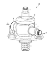
- FIG. 1 is a perspective view of a fuel supply pump 10 according to the first embodiment.
- the fuel supply pump 10 is a constituent element of an automobile, and supplies gasoline with a high pressure to the engine.
- the fuel supply pump 10 includes a pump body 1, a capacity control joint 9 and a discharge joint 2 welded to the pump body 1, a suction joint 7, a damper holder 72, and a piston plunger 8.
- the fuel supply pump 10 sucks gasoline in a gasoline fuel tank (not shown) from the suction joint 7, increases the pressure inside the pump body 1, discharges it from the discharge joint 2, and supplies it to the engine (not shown).
- the fuel supply pump 10 is a joined body assembled by welding. Therefore, a welded structure that can withstand the high pressure of the fuel (medium) is desired.
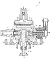
- FIG. 2 is a sectional view of the fuel supply pump 10 shown in FIG. 1 taken along the line II-II.
- a damper holder 72 is fitted into the pump body 1 to fix the damper 71.
- the suction joint 7 is joined to the damper holder 72.
- a capacity control joint 9 is welded to the pump body 1.
- the capacity control joint 9 includes an electromagnetic valve 92, a spring 94 that biases the electromagnetic valve 92, and an electromagnetic coil 93 that drives the electromagnetic valve 92. In a state where the electromagnetic coil 93 is not energized and there is no fluid differential pressure between the suction passage and the pressurizing chamber 83, the electromagnetic valve 92 is urged to the right in FIG.
- the suction valve body 95 at the tip of the electromagnetic valve 92 is urged in the valve closing direction, and the pressurizing chamber 83 is closed.
- the electromagnetic valve 92 is maintained in a state of moving leftward in FIG.
- the suction valve body 95 at the tip of the electromagnetic valve 92 opens the suction port 96 connected to the pressurizing chamber 83.
- a piston plunger 8 and a cylinder 81 are fitted into the pump body 1 on the opposite side of the suction joint 7.
- the pump body 1, the piston plunger 8 and the cylinder 81 constitute a pressurizing chamber 83.
- the cylinder 81 is fixed to the pump body 1 by a cylinder holder 82.
- the discharge joint 2 is welded to the pump body 1 on the opposite side of the capacity control joint 9, and a discharge valve mechanism 26 is provided therein.
- the gasoline sucked from the suction joint 7 is made to flow statically through the vicinity of the damper 71. Thereafter, the gasoline passes in the vicinity of the electromagnetic valve 92.
- the electromagnetic valve 92 is driven to open and close by an electromagnetic coil 93 to control the gasoline flow rate.
- the gasoline is pressurized in the pressurizing chamber 83 by the reciprocating motion of the piston plunger 8.
- the piston plunger 8 is urged downward in FIG. 2 by a spring or the like, and further pushed upward by a cam mechanism (not shown).
- the gasoline whose pressure has been increased in the pressurizing chamber 83 is discharged from the discharge joint 2 via the discharge valve mechanism 26 and supplied to the engine (not shown).
- the fuel supply pump 10 since the gasoline is repeatedly increased in pressure, the stress generated in each welded portion is also increased, and a decrease in fatigue strength of each welded portion becomes a problem.
- the first welded portion is a welded portion between the discharge joint 2 and the pump body 1 and is the position of the butt surface 3.
- the second welded portion is a welded portion between the capacity control joint 9 and the pump body 1 and is the position of the butt surface 91. All of these welded portions are annular, and are sealed and welded over the entire circumference.
- the present invention is particularly effective for these two welding sites.
- part of the discharge joint 2 and the pump body 1 is demonstrated in each embodiment, it is applicable similarly to the welding site
- FIG. 3 is a perspective view and a partial sectional view of the discharge joint 2 as viewed from below.
- the discharge joint 2 has a substantially cylindrical shape, and a columnar space 5 in which gasoline pressure acts is provided inside.
- the fitting portion 22 of the discharge joint 2 protrudes so as to extend the columnar space 5.
- the outer diameter of the fitting portion 22 is substantially equal to the inner diameter of the pump body 1 shown in FIG.
- the fitting portion 22 is fitted to the inner periphery of the pump body 1.
- An annular surface 23 that is an annular depression is formed at the base of the outer periphery of the fitting portion 22.
- a flat surface 24 is formed on the outer periphery of the annular surface 23.
- the side surface of the discharge joint 2 is a discharge joint surface 21.
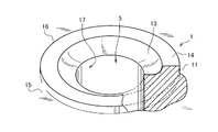
- FIG. 4 is a perspective view and a partial cross-sectional view of the pump body 1 as viewed from above.
- the pump body 1 is configured to include a main body 15 and a cylindrical portion 16 formed on the main body 15.
- the pump body 1 is provided with a cylindrical space 5 (see FIG. 1) in which gasoline pressure acts.
- a side surface of the cylindrical portion 16 is a pump body surface 11.
- the upper surface of the cylindrical portion 16 is formed to include a flat surface 14 and a concave annular surface 13 that is a recess on the inner peripheral side of the flat surface 14.
- a cylindrical space 5 is provided on the inner periphery of the annular surface 13.
- the inner peripheral surface 17 of the cylinder portion 16 of the pump body 1 is fitted with the fitting portion 22 of the discharge joint 2 shown in FIG.
- the flat surface 14 of the pump body 1 is laser welded after being brought into contact with the flat surface 24 of the discharge joint 2.
- a cross section of the joined body 60 at this time is shown in FIG.
- FIG. 5 is a perspective view of the joined body after welding.
- the welded joined body 60 includes the discharge joint 2, the pump body 1, and the annular welded portion 6 that welds and connects them.
- the annular welded portion 6 is inclined with respect to the normal of the inner circumferential curved surface 61 connecting the boundary between the annular welded portion 6 and the pump body 1 on the inner peripheral side and the boundary between the discharge joint 2.
- the center of the outer peripheral curved surface 62 connecting the boundary between the pump body 1 on the outer peripheral side of the welded portion 6 and the boundary between the discharge joint 2 is in the axial direction of the cylindrical space 5 with respect to the center of the inner peripheral curved surface 61.
- the inner circumferential curved surface 61 which is shifted here is not a welding back surface itself but a virtual curved surface connecting a boundary between the welding back surface and the pump body 1 and a boundary between the discharge joint 2.
- the outer peripheral curved surface 62 is not a welding surface itself but a virtual curved surface connecting a boundary between the welding surface and the pump body 1 and a boundary between the discharge joint 2.
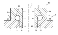
- FIG. 6 is a cross-sectional view of the joined body 60 before welding.
- the joined body 60 before welding includes a pump body 1 (first member) and a discharge joint 2 (second member).
- the columnar space 5 is provided inside the discharge joint 2 and the pump body 1, where gasoline as a medium flows and pressure acts.
- the butted surface 3 of the joined body 60 is a surface sealed by welding.
- An annular space 4 is formed between the butting surface 3 and the cylindrical space 5.
- the fitting portion 22 of the discharge joint 2 is press-fitted into the pump body 1 to form a fitting surface 31.
- the fitting surface 31 is formed by the outer periphery of the fitting part 22 and the inner periphery of the pump body 1.
- the annular space 4 is closed by the fitting portion 22 to form a torus shape, and is separated from the cylindrical space 5. Therefore, spatter generated by welding remains in the annular space 4. In other words, the annular space 4 prevents spatter generated by welding from entering the cylindrical space 5.
- the laser beam L is irradiated with being inclined with respect to the butted surface 3.
- the laser beam L for welding the butt surface 3 is inclined toward the discharge joint 2 at the outer periphery of the cylindrical space 5.
- the laser beam L is inclined toward the pump body 1 on the inner periphery of the cylindrical space 5.
- the irradiation position of the laser beam L is a position shifted to the discharge joint surface 21 side instead of the butting surface 3. This is to ensure solidification while melting the vicinity of the butting surface 3 up to the cylindrical space 5 side.
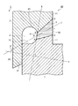
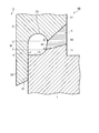
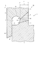
- FIG. 7 is a cross-sectional view of the joined body 60 after welding in the first embodiment.
- the welded joined body 60 includes the discharge joint 2, the pump body 1, and the annular welded portion 6 that welds and connects them.
- the annular welded portion 6 faces the outside at the welding surface 62s and faces the cylindrical space 5 at the welding back surface 61s.
- An outer peripheral curved surface 62 that is a virtual curved surface connecting the boundary between the welding surface 62 s and the pump body 1 and the boundary between the discharge joint 2 is located inside the welding surface 62 s.
- an inner peripheral curved surface 61 that is a virtual curved surface connecting the boundary between the welding back surface 61 s and the pump body 1 and the boundary between the discharge joint 2 is located inside the welding back surface 61 s.
- the joined body 60 is formed by irradiating the laser beam L with an inclination with respect to the abutting surface 3 and laser welding the discharge joint 2 and the pump body 1. Due to the inclination of the laser beam L, the annular welded portion 6 also has an inclined shape corresponding thereto. Since the butted surface 3 is completely melted and solidified and disappears, the welding back surface 61s reaches the annular space 4. This is to prevent the butted surface 3 from remaining undissolved and causing a decrease in fatigue strength. By this oblique irradiation, the entire circumference is sealed and welded to form the annular welded portion 6 to improve the fatigue strength.
- the principle is as follows.
- FIG. 8 is an enlarged cross-sectional view for explaining the welded shape of the joined body 60 in the first embodiment.
- the pump body 1 and the discharge joint 2 are welded by an annular weld 6.
- An annular space 4 is formed facing the inner circumferential curved surface 61.
- the annular space 4 is closed by the fitting portion 22 and separated from the cylindrical space 5. Due to the blockage of the fitting portion 22, welding spatter is prevented from entering the cylindrical space 5.
- a point where the welding surface 62s and the surface of the pump body 1 are in contact with each other is defined as a C point. This point C is a boundary with the pump body 1 on the outer peripheral side of the annular welded portion 6.
- a point where the welding surface 62s and the surface of the discharge joint 2 are in contact with each other is defined as a point D.
- This point D is the boundary between the inner circumference side of the annular welded portion 6 and the pump body 1 and the discharge joint 2. Further, an intermediate point between point C and point D is set as point I.
- Point I is one point on the center line of the outer peripheral curved surface 62.
- a point where the welding back surface 61s (see FIG. 7) and the surface of the pump body 1 are in contact with each other is referred to as a point A.
- a point is a boundary with the pump body 1 on the inner peripheral side of the annular welded portion 6.
- a point where the weld back surface 61s and the surface of the discharge joint 2 are in contact with each other is defined as a B point.
- Point B is the boundary between the inner peripheral side of the annular welded portion 6 and the pump body 1 and the discharge joint 2.
- a straight line connecting points A and B is defined as a straight line E.
- a perpendicular line of the straight line E is a straight line F.
- a line connecting point I and point H is defined as a straight line J.
- the straight line F is inclined with respect to the straight line J by an angle ⁇ . The fatigue strength can be improved by this inclination.
- the straight line J connects the center of the outer peripheral curved surface 62 of the annular welded portion 6 and the center of the inner peripheral curved surface 61. That is, the annular welded portion 6 is inclined with respect to the straight line F by an angle ⁇ .
- This angle ⁇ is between 10 degrees and 50 degrees, and it was confirmed by experiments that it is effective for improving the fatigue strength.
- the angle ⁇ is 10 ° or less, the inclination angle is too small to increase the back surface width W (see FIG. 9) of the inner circumferential curved surface 61, and the effect of improving the fatigue strength cannot be obtained.
- the angle ⁇ is 50 ° or more, the back surface width W is widened, but the inclination angle is too large, the laser welding itself becomes unstable, the amount of spatter is increased, and welding defects such as porosity are likely to occur. . Therefore, the angle ⁇ is optimally 10 to 50 °.
- FIG. 9 is an enlarged cross-sectional view for explaining the thickness of the inner peripheral curved surface 61 of the joined body 60 in the first embodiment.
- the straight line F and the straight line J can be inclined, and the back surface width W of the inner peripheral curved surface 61 can be increased. Since high-pressure gasoline flows into the columnar space 5 and pressure acts, stress is generated on the inner circumferential curved surface 61. Reducing this stress is effective for improving fatigue strength. Therefore, the back surface width W is widened so that the contact angle between the inner peripheral curved surface 61 and the annular surface 13 of the pump body 1 becomes flat.
- the contact angle between the inner peripheral curved surface 61 and the annular surface 23 of the discharge joint 2 is also made flat. That is, as the contact angle becomes obtuse, the stress generated at the points A and B by the high-pressure gasoline is reduced, and the fatigue strength can be improved.
- the annular surface 23 on the discharge joint 2 side and / or the annular surface 13 on the pump body 1 side is a concave surface. By providing this concave surface, the rise of the weld back surface 61s (see FIG. 7) can be reduced, and the stress generated at the points A and B can be further reduced.
- FIG. 10 is a cross-sectional view illustrating the weld thickness of the joined body 60 after welding in the first embodiment.
- the thickness from the point A to the pump body surface 11 is a distance Y.
- the thickness from the point B to the welding surface 62s is a distance X.
- the pump body 1 is thicker and more rigid than the discharge joint 2. For this reason, when high-pressure gasoline flows, a greater stress is generated at point A on the pump body 1 side than point B on the discharge joint 2 side. Therefore, it is necessary to reduce the stress at the point A more than the stress at the point B.
- the distance Y on the A point side can be made thicker than the distance X on the B point side. Thereby, the rigidity in the vicinity of the point A is increased, the stress generated at the point A can be reduced, and the fatigue strength can be improved.
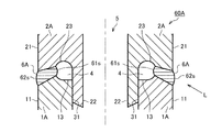
- FIG. 11 is a cross-sectional view of the joined body 60A after welding in the second embodiment.
- the joined body 60A of the second embodiment includes a pump body 1A having a shape different from that of the first embodiment, a discharge joint 2A, and an annular welded portion 6A in which these are connected and welded.
- the cross section of the annular welded portion 6A is inclined obliquely with respect to the radial direction of the columnar space 5.
- the inclination of the annular welded portion 6A is opposite to that of the first embodiment, and the outer periphery of the pump body 1A. It is inclined to the side, and is inclined to the discharge joint 2A side on the inner periphery.
- the difference from the first embodiment is that the irradiation direction of the laser light L is irradiated to the pump body 1 side on the outer peripheral side of the cylindrical space 5 and to the discharge joint 2 side on the inner peripheral side. It is. Thus, even if the irradiation direction of the laser beam L is different and the inclination of the annular welded portion 6A is different, the fatigue strength of welding can be improved as in the first embodiment.
- FIG. 12 is a cross-sectional view of the joined body 60B after welding in the third embodiment.
- the joined body 60B of the third embodiment includes a pump body 1B having a shape different from that of the first embodiment, a discharge joint 2B, and an annular welded portion 6B in which these are connected and welded.
- a sputter cover 51 is provided on the inner periphery of the pump body 1B and the inner periphery of the discharge joint 2B, in which the cross section of the annular welded portion 6B is inclined obliquely with respect to the radial direction of the columnar space 5.
- the joined body 60B of the third embodiment is not formed with the annular space 4, and a sputter cover 51 is provided instead.
- the sputter cover 51 prevents welding spatter from entering the cylindrical space 5. After welding, the sputter cover 51 is removed for operation. Even when the annular space 4 is not formed as described above, the fatigue strength of welding can be improved as in the first embodiment.
- FIG. 13 is a cross-sectional view of the joined body 60C after welding in the fourth embodiment.
- the joined body 60C according to the fourth embodiment includes a pump body 1C having a shape different from that of the first embodiment, a discharge joint 2C, and an annular welded portion 6C in which these are connected and welded.
- the cross section of the annular welded portion 6 ⁇ / b> C is inclined obliquely with respect to the radial direction of the cylindrical space 5.
- the joined body 60 ⁇ / b> C of the fourth embodiment is different from the joined body 60 of the first embodiment in that the fitting portion 12 is attached to the pump body 1.
- the fatigue strength of welding can be improved similarly to 1st Embodiment.
- FIG. 14 is a cross-sectional view of the joined body 60D before welding in the fifth embodiment.
- the joined body 60D of the fifth embodiment includes a pump body 1D and a discharge joint 2D having a shape different from that of the first embodiment.
- the joined body 60D of the fifth embodiment is such that the pump body surface 11 and the discharge joint surface 21 near the butt surface 3 are inclined with respect to the central axis of the cylindrical space 5. ing. That is, the outer diameter of the pump body 1D increases as it goes from the butting surface 3 toward the pump body 1D. On the contrary, the outer diameter of the discharge joint 2D becomes smaller as it goes to the discharge joint 2D side from the butt surface 3. Furthermore, the butting surface 3 is inclined with respect to the radial direction of the cylindrical space 5.
- FIG. 15 shows a cross-sectional view after welding in the fifth embodiment.
- the joined body 60D of the fifth embodiment includes a pump body 1D and a discharge joint 2D having a shape different from that of the first embodiment, and an annular welded portion 6D in which these are connected and welded.
- the cross section of the annular weld 6D is inclined obliquely with respect to the radial direction of the cylindrical space 5.
- the fatigue strength of the annular welded portion 6D can be improved.
- the pump body 1D can be thickened in the vicinity of the annular weld 6D, which is more effective in improving the fatigue strength than in the first embodiment.
- the present invention is not limited to the embodiments described above, and includes various modifications.
- the above-described embodiment has been described in detail for easy understanding of the present invention, and is not necessarily limited to the one having all the configurations described.
- a part of the configuration of one embodiment can be replaced with the configuration of another embodiment, and the configuration of another embodiment can be added to the configuration of one embodiment.
- modifications of the present invention include the following (a) to (d).
- (A) The joined body of the said embodiment is not restricted to the fuel supply pump 10, You may be used for arbitrary pumps.
- the joined body of the above embodiment is not limited to welding between the pump body 1D and the discharge joint 2D, and may be applied to welding between the pump body 1D and the capacity control joint 9.
- C As in the capacity control joint 9, a member in which the columnar space 5 is not formed may be used as the second member.
- the space inside the joined body is not limited to a cylindrical shape, but may be an arbitrary shape such as an elliptical shape or a polygonal column shape.
Landscapes
- Engineering & Computer Science (AREA)
- Mechanical Engineering (AREA)
- Physics & Mathematics (AREA)
- Optics & Photonics (AREA)
- Chemical & Material Sciences (AREA)
- Combustion & Propulsion (AREA)
- General Engineering & Computer Science (AREA)
- Plasma & Fusion (AREA)
- Fuel-Injection Apparatus (AREA)
- Laser Beam Processing (AREA)
Abstract
接合体の溶接部を厚くせずに高圧に耐える。接合体60は、媒体の圧力が作用するる円柱状空間5が内部に形成されたポンプボディ1と、ポンプボディ1に嵌め合う吐出ジョイント2と、円柱状空間5の外周側に設けられ、ポンプボディ1と吐出ジョイント2とを溶接して連結する環状溶接部6とを備える。環状溶接部6は、この環状溶接部6の内周側のポンプボディ1との境界と吐出ジョイント2との境界とを結ぶ内周側曲面の垂線に対して、所定角θだけ傾斜している、
Description
本発明は、溶接部を含む接合体および燃料供給ポンプに関するものである。
近年、自動車エンジンに燃料を供給する燃料供給ポンプでは、燃料圧力の上昇により燃費向上させる技術が進められており、より高圧に耐える溶接構造が求められている。
この燃料供給ポンプは、円柱状空間が内部に形成された複数の部材を含んで構成される。この複数の部材が溶接されて環状溶接部を形成し、その内部の円柱状空間に媒体(燃料)が流れる。この燃料が高圧の場合には、環状溶接部の内面側の表面に応力が発生し、溶接の疲労強度が低下して亀裂が発生するという問題があった。
この燃料供給ポンプは、円柱状空間が内部に形成された複数の部材を含んで構成される。この複数の部材が溶接されて環状溶接部を形成し、その内部の円柱状空間に媒体(燃料)が流れる。この燃料が高圧の場合には、環状溶接部の内面側の表面に応力が発生し、溶接の疲労強度が低下して亀裂が発生するという問題があった。
特許文献1の課題には、「製造コストを低減しつつ、溶接強度を高め、信頼性を向上することができる流体機械を提供する。」と記載されている。同文献の解決手段には、「第1及び第2シェル(78,80)は、これらの各開口端部(78a,80a)を突き合わせて形成される開先部(82)に全周溶接をして溶接部(84)を形成し、溶接部は、各開口端部にて互いに当接されるシール部(96,98)と所定の空間(100)を存して離間する。」と記載されている。同文献の段落0010には、「空間を形成することにより、溶接部への応力集中が緩和されるため、亀裂の発生が抑制され、更に、溶接時に飛散するスパッタや火花が密閉容器内に侵入することを防止し、また、溶接部が密閉容器内にまで至ることを防止しながら、溶接部ののど厚を確保して溶接強度を高めることができるため、流体機械の信頼性を向上することができる。」と記載されている。
特許文献1に記載の技術によれば、溶接裏面が媒体流路側に盛り上がり、高圧にさらされて溶接疲労強度が低下するおそれがある。この盛り上がりを抑制して溶接疲労強度をさらに向上させることは、同文献には記載されていない。また、同文献に記載の溶接法はアーク溶接であり、レーザ溶接に関する技術は記載されていない。
そこで、本発明は、溶接の疲労強度を向上させる接合体の構造を提供するとともに、それを用いた燃料供給ポンプを提供することを課題とする。
前記した課題を解決するため、本発明の接合体は、媒体の圧力が作用する空間が内部に形成された第1部材と、前記第1部材に嵌め合う第2部材と、前記空間の外周側に設けられ、前記第1部材と前記第2部材とを溶接して連結する環状溶接部を備え、前記環状溶接部は、当該環状溶接部の内周側の前記第1部材との境界と前記第2部材との境界とを結ぶ内周側曲面の垂線に対して、所定角だけ傾斜して形成されていることを特徴とする接合体とした。
その他の手段については、発明を実施するための形態のなかで説明する。
その他の手段については、発明を実施するための形態のなかで説明する。
本発明によれば、溶接の疲労強度を向上させる接合体の構造を提供することと、それを用いた燃料供給ポンプを提供することが可能となる。
以降、本発明を実施するための形態を、各図を参照して詳細に説明する。
(第1の実施形態)
図1は、第1の実施形態における燃料供給ポンプ10の斜視図である。
燃料供給ポンプ10は、自動車の構成要素であり、ガソリンを高圧化してエンジンに供給する。燃料供給ポンプ10は、ポンプボディ1と、これに溶接された容量制御ジョイント9および吐出ジョイント2と、吸入ジョイント7と、ダンパーホルダ72と、ピストンプランジャー8とを含んで構成される。燃料供給ポンプ10は、ガソリン燃料タンク(不図示)のガソリンを吸入ジョイント7から吸入し、ポンプボディ1の内部で高圧化させて、吐出ジョイント2から吐出させてエンジン(不図示)に供給する。
近年、エンジンの燃費向上を目的に、ガソリンをより高圧化させてエンジンに供給する燃料供給ポンプが要求されている。燃料供給ポンプ10は、溶接で組み立てられる接合体である。そのため、燃料(媒体)の高圧化に耐える溶接構造が望まれる。
図2は、図1に示す燃料供給ポンプ10のII-II断面図である。
ポンプボディ1には、ダンパーホルダ72が嵌め込まれて、ダンパー71を固定している。このダンパーホルダ72には吸入ジョイント7が接合される。
ポンプボディ1には、容量制御ジョイント9が溶接されている。この容量制御ジョイント9は、電磁バルブ92と、これを付勢するバネ94と、これを駆動する電磁コイル93とを含んで構成される。
電磁コイル93が通電されておらず、かつ吸入通路と加圧室83との間の流体差圧が無い状態にて、電磁バルブ92は、バネ94で図2の右方に付勢される。電磁バルブ92の先端の吸入弁体95が閉弁方向に付勢され、加圧室83は閉じられた状態となる。電磁コイル93が通電されている状態にて、電磁バルブ92は、図1の左方に移動した状態が維持される。このとき電磁バルブ92の先端の吸入弁体95は、加圧室83につながる吸入口96を開いている。
ポンプボディ1には、吸入ジョイント7の反対側にピストンプランジャー8とシリンダ81とが嵌め込まれている。ポンプボディ1とピストンプランジャー8とシリンダ81によって、加圧室83が構成される。シリンダ81は、シリンダホルダ82によってポンプボディ1に固定される。
ポンプボディ1には更に、容量制御ジョイント9の反対側に、吐出ジョイント2が溶接され、その内部に吐出弁機構26を備える。
ポンプボディ1には更に、容量制御ジョイント9の反対側に、吐出ジョイント2が溶接され、その内部に吐出弁機構26を備える。
以下、この燃料供給ポンプ10の動作を説明する。
吸入ジョイント7から吸入されたガソリンは、ダンパー71近傍を通って静流化される。その後ガソリンは、電磁バルブ92の近傍を通る。電磁バルブ92は、電磁コイル93によって開閉駆動されて、このガソリンの流量をコントルールする。
吸入ジョイント7から吸入されたガソリンは、ダンパー71近傍を通って静流化される。その後ガソリンは、電磁バルブ92の近傍を通る。電磁バルブ92は、電磁コイル93によって開閉駆動されて、このガソリンの流量をコントルールする。
更にガソリンは、加圧室83において、ピストンプランジャー8の往復運動により高圧化される。ピストンプランジャー8は、バネ等によって図2の下方向に付勢され、更に不図示のカム機構によって上方向に押し上げられる。加圧室83で高圧化されたガソリンは、吐出弁機構26を介して吐出ジョイント2から吐出され、エンジン(不図示)に供給される。
燃料供給ポンプ10内では、繰り返しガソリンが高圧化されるため、各溶接部に発生する応力も大きくなり、各溶接部の疲労強度の低下が問題となる。燃料供給ポンプ10内の特に圧力の高い溶接部は2か所ある。第1溶接部は、吐出ジョイント2とポンプボディ1との溶接部位であり、突合せ面3の位置である。第2溶接部は、容量制御ジョイント9とポンプボディ1との溶接部位であり、突合せ面91の位置である。これらの溶接部位は、いずれも環状であり、一周に亘って封止溶接されている。本発明は、この二つの溶接部位に特に有効である。
以下、各実施形態において吐出ジョイント2とポンプボディ1の溶接部位について説明するが、容量制御ジョイント9とポンプボディ1の溶接部位にも同様にして適用可能である。
図3は、吐出ジョイント2を下方から見たときの斜視図および部分断面図である。
吐出ジョイント2は、ほぼ円筒形であり、ガソリンの圧力が作用する円柱状空間5が内部に設けられている。吐出ジョイント2の勘合部22は、この円柱状空間5を延長するように突出している。勘合部22の外径は、後記する図4に示すポンプボディ1の内径とほぼ同等である。勘合部22は、ポンプボディ1の内周に勘合する。
勘合部22の外周の根元には、環状の窪みである環状面23が形成されている。環状面23の外周には、平面24が形成されている。そして、この吐出ジョイント2の側面は、吐出ジョイント表面21である。
吐出ジョイント2は、ほぼ円筒形であり、ガソリンの圧力が作用する円柱状空間5が内部に設けられている。吐出ジョイント2の勘合部22は、この円柱状空間5を延長するように突出している。勘合部22の外径は、後記する図4に示すポンプボディ1の内径とほぼ同等である。勘合部22は、ポンプボディ1の内周に勘合する。
勘合部22の外周の根元には、環状の窪みである環状面23が形成されている。環状面23の外周には、平面24が形成されている。そして、この吐出ジョイント2の側面は、吐出ジョイント表面21である。
図4は、ポンプボディ1を上方から見たときの斜視図および部分断面図である。
ポンプボディ1は、本体15と、この本体15上に形成された筒部16とを含んで構成される。ポンプボディ1は、ガソリンの圧力が作用する円柱状空間5(図1参照)が内部に設けられている。
筒部16の側面は、ポンプボディ表面11である。筒部16の上面は、平面14と、この平面14の内周側の窪みである凹状の環状面13とを含んで形成される。環状面13の更に内周は、円柱状空間5が設けられている。
このポンプボディ1の筒部16の内周面17は、図3に示した吐出ジョイント2の勘合部22が圧入されて勘合する。ポンプボディ1の平面14は、吐出ジョイント2の平面24と突き合わせられたのちにレーザ溶接される。このときの接合体60の断面を、後記する図5に示す。
図5は、溶接後の接合体の斜視図である。
溶接後の接合体60は、吐出ジョイント2とポンプボディ1と、これらを溶接して連結する環状溶接部6とを含んで構成される。この環状溶接部6は、この環状溶接部6の内周側のポンプボディ1との境界と吐出ジョイント2との境界とを結ぶ内周側曲面61の垂線に対して傾斜している、つまり環状溶接部6の外周側のポンプボディ1との境界と吐出ジョイント2との境界とを結ぶ外周側曲面62の中央は、この内周側曲面61の中央に対して円柱状空間5の軸線方向にずれている、ここで内周側曲面61とは、溶接裏面そのものではなく、溶接裏面とポンプボディ1との境界と吐出ジョイント2との境界とを結ぶ仮想的な曲面である。外周側曲面62も同様に、溶接表面そのものではなく、溶接表面とポンプボディ1との境界と吐出ジョイント2との境界とを結ぶ仮想的な曲面である。
溶接後の接合体60は、吐出ジョイント2とポンプボディ1と、これらを溶接して連結する環状溶接部6とを含んで構成される。この環状溶接部6は、この環状溶接部6の内周側のポンプボディ1との境界と吐出ジョイント2との境界とを結ぶ内周側曲面61の垂線に対して傾斜している、つまり環状溶接部6の外周側のポンプボディ1との境界と吐出ジョイント2との境界とを結ぶ外周側曲面62の中央は、この内周側曲面61の中央に対して円柱状空間5の軸線方向にずれている、ここで内周側曲面61とは、溶接裏面そのものではなく、溶接裏面とポンプボディ1との境界と吐出ジョイント2との境界とを結ぶ仮想的な曲面である。外周側曲面62も同様に、溶接表面そのものではなく、溶接表面とポンプボディ1との境界と吐出ジョイント2との境界とを結ぶ仮想的な曲面である。
図6は、溶接前の接合体60の断面図である。
溶接前の接合体60は、ポンプボディ1(第1部材)と吐出ジョイント2(第2部材)とを含んで構成される。円柱状空間5は、吐出ジョイント2とポンプボディ1の内部に設けられており、ここに媒体であるガソリンが流れ、圧力が作用する。
接合体60の突合せ面3は、溶接によって封止される面である。突合せ面3と円柱状空間5の間には、環状空間4が形成されている。吐出ジョイント2の勘合部22は、ポンプボディ1に圧入されて勘合面31を形成する。勘合面31は、勘合部22の外周とポンプボディ1の内周とで形成される。
環状空間4は、勘合部22によって閉塞されてトーラス状となり、円柱状空間5と分離されている。よって溶接で発生したスパッタは、この環状空間4内に留まる。言い換えると、環状空間4は、溶接で発生したスパッタが円柱状空間5内に混入するのを防止している。
接合体60の突合せ面3を溶接するには、レーザ光Lを、突合せ面3に対して傾斜させて照射させる。突合せ面3を溶接するレーザ光Lは、円柱状空間5の外周では吐出ジョイント2側に傾斜する。レーザ光Lは、円柱状空間5の内周ではポンプボディ1側に傾斜する。また、レーザ光Lの照射位置は、突合せ面3ではなく、吐出ジョイント表面21の側にずらした位置である。これは、円柱状空間5側まで突合せ面3近傍を溶融しつつ確実に凝固させるためである。
図7は、第1の実施形態における溶接後の接合体60の断面図である。
溶接後の接合体60は、吐出ジョイント2とポンプボディ1と、これらを溶接して連結する環状溶接部6とを含んで構成される。環状溶接部6は、溶接表面62sで外界に面すると共に、溶接裏面61sで円柱状空間5に面している。溶接表面62sの内側には、溶接表面62sとポンプボディ1との境界と吐出ジョイント2との境界とを結ぶ仮想的な曲面である外周側曲面62が位置する。また溶接裏面61sの内側には、溶接裏面61sとポンプボディ1との境界と吐出ジョイント2との境界とを結ぶ仮想的な曲面である内周側曲面61が位置する。
溶接後の接合体60は、吐出ジョイント2とポンプボディ1と、これらを溶接して連結する環状溶接部6とを含んで構成される。環状溶接部6は、溶接表面62sで外界に面すると共に、溶接裏面61sで円柱状空間5に面している。溶接表面62sの内側には、溶接表面62sとポンプボディ1との境界と吐出ジョイント2との境界とを結ぶ仮想的な曲面である外周側曲面62が位置する。また溶接裏面61sの内側には、溶接裏面61sとポンプボディ1との境界と吐出ジョイント2との境界とを結ぶ仮想的な曲面である内周側曲面61が位置する。
この接合体60は、レーザ光Lを突合せ面3に対して傾斜させて照射して、吐出ジョイント2とポンプボディ1とがレーザ溶接されて形成される。レーザ光Lの傾斜により、環状溶接部6も、それに対応した傾斜した形状になる。突合せ面3が完全に溶融凝固して消失するので、溶接裏面61sは、環状空間4に達する。突合せ面3が溶け残り、疲労強度低下の原因になるのを抑制するためである。この傾斜照射により、全周の封止溶接をして環状溶接部6を形成させ、疲労強度を向上させる。その原理を次に示す。
図8は、第1の実施形態における接合体60の溶接形状を説明する拡大断面図である。
ポンプボディ1と吐出ジョイント2は、環状溶接部6で溶接されている。内周側曲面61に面して環状空間4が形成されている。この環状空間4は、勘合部22によって閉塞され、円柱状空間5と分離されている。この勘合部22の閉塞により、溶接スパッタが円柱状空間5に混入するのを防止している。
溶接表面62sとポンプボディ1の表面とが接触する点を、C点とする。このC点は、環状溶接部6の外周側のポンプボディ1との境界である。また、溶接表面62sと吐出ジョイント2の表面が接触する点を、D点とする。このD点は、環状溶接部6の内周側のポンプボディ1との境界と吐出ジョイント2との境界である。更に、C点とD点との中間点をI点とする。
C点とD点を結ぶ曲線を、円柱状空間5の軸線を中心に回転させると、環状溶接部6の外周側曲面62となる。I点は、この外周側曲面62の中央線上の1点である。
溶接裏面61s(図7参照)とポンプボディ1の表面とが接触する点を、A点とする。A点は、環状溶接部6の内周側のポンプボディ1との境界である。また、溶接裏面61sと吐出ジョイント2の表面が接触する点を、B点とする。B点は、環状溶接部6の内周側のポンプボディ1との境界と吐出ジョイント2との境界である。更にA点とB点の中間点をH点とする。A点とB点を結ぶ直線を、直線Eとする。直線Eの垂線を、直線Fとする。また、I点とH点を結んだ線を、直線Jとする。直線Fは、直線Jに対して角度θだけ傾斜している。この傾斜により疲労強度を向上させることができる。
A点とB点を結ぶ直線Eを、円柱状空間5の軸線を中心に回転させると、環状溶接部6の内周側曲面61となる。この内周側曲面61の垂線は、直線Fである。直線Jは、環状溶接部6の外周側曲面62の中央と前記内周側曲面61の中央とを結んでいる。つまり、環状溶接部6は、直線Fに対して角度θだけ傾斜している。この角度θとしては10度から50度までの間で、疲労強度の向上に有効であることを実験で確認した。
角度θが10°以下では、傾斜角度が小さすぎて内周側曲面61の裏面幅W(図9参照)を広くすることができず、疲労強度向上の効果が得られなかった。一方、角度θが50°以上では、裏面幅Wは広くなるものの、傾斜角度が大きすぎてレーザ溶接そのものが不安定になりスパッタの発生量が増えて、ポロシティなどの溶接欠陥が発生しやすくなる。そのため、角度θは10~50°が最適であった。
図9は、第1の実施形態における接合体60の内周側曲面61の厚さを説明するための拡大断面図である。
レーザ光Lを傾斜させて照射することにより、直線Fと直線J(図7参照)とを傾斜させることができ、内周側曲面61の裏面幅Wを広くすることができる。
円柱状空間5に高圧のガソリンが流れ、圧力が作用するため、内周側曲面61には、応力が発生する。この応力を低減することが疲労強度向上に有効である。そのため、裏面幅Wを広くして、内周側曲面61とポンプボディ1の環状面13との接触角を平坦になるようにしている。また、内周側曲面61と吐出ジョイント2の環状面23との接触角も平坦になるようにしている。すなわち接触角が鈍角になるほど、高圧のガソリンによりA点およびB点に発生する応力が小さくなり、疲労強度を向上させることができる。
また、吐出ジョイント2側の環状面23または/およびポンプボディ1側の環状面13は、凹面である。この凹面を設けることで、溶接裏面61s(図7参照)の盛り上がりを少なくでき、A点およびB点に発生する応力を更に低減できる。
図10は、第1の実施形態における溶接後の接合体60の溶接厚さを述べた断面図である。
A点からポンプボディ表面11までの厚みを、距離Yとする。B点から溶接表面62sまでの厚みを、距離Xとする。ポンプボディ1は、吐出ジョイント2に比べて肉厚であり剛性が高い。そのため、高圧のガソリンが流れる際には、吐出ジョイント2側のB点よりポンプボディ1側のA点の方に大きな応力が発生する。そのため、A点の応力をB点の応力よりも低減することが必要である。
第1の実施形態では、レーザ光Lを傾斜させて照射するため、B点側の距離XよりもA点側の距離Yの方を厚くすることができる。これによりA点近傍の剛性が高くなり、A点に発生する応力を低減でき、疲労強度を向上させることができる。
A点からポンプボディ表面11までの厚みを、距離Yとする。B点から溶接表面62sまでの厚みを、距離Xとする。ポンプボディ1は、吐出ジョイント2に比べて肉厚であり剛性が高い。そのため、高圧のガソリンが流れる際には、吐出ジョイント2側のB点よりポンプボディ1側のA点の方に大きな応力が発生する。そのため、A点の応力をB点の応力よりも低減することが必要である。
第1の実施形態では、レーザ光Lを傾斜させて照射するため、B点側の距離XよりもA点側の距離Yの方を厚くすることができる。これによりA点近傍の剛性が高くなり、A点に発生する応力を低減でき、疲労強度を向上させることができる。
(第2の実施形態)
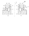
図11は、第2の実施形態における溶接後の接合体60Aの断面図である。
第2の実施形態の接合体60Aは、第1実施形態とは異なる形状のポンプボディ1Aと吐出ジョイント2Aと、これらを連結して溶接した環状溶接部6Aとを含んで構成される。環状溶接部6Aの断面は、円柱状空間5の径方向に対して斜めに傾斜している、環状溶接部6Aの傾斜は、第1の実施形態とは逆方向であり、外周ではポンプボディ1A側に傾斜し、内周では吐出ジョイント2A側に傾斜している。
第1の実施形態と異なる点は、レーザ光Lの照射方向を、円柱状空間5の外周側ではポンプボディ1の側に、内周側では吐出ジョイント2側に傾斜させて照射させていることである。このように、レーザ光Lの照射方向が異なり、環状溶接部6Aの傾斜が異なっても第1の実施形態と同様に、溶接の疲労強度を向上させることができる。
(第3の実施形態)
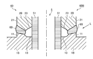
図12は、第3の実施形態における溶接後の接合体60Bの断面図である。
第3の実施形態の接合体60Bは、第1実施形態とは異なる形状のポンプボディ1Bと吐出ジョイント2Bと、これらを連結して溶接した環状溶接部6Bとを含んで構成される。環状溶接部6Bの断面は、円柱状空間5の径方向に対して斜めに傾斜している、ポンプボディ1Bの内周と、吐出ジョイント2Bの内周には、スパッタカバー51が設けられる。
第3の実施形態の接合体60Bは、第1の実施形態の接合体60とは異なり、環状空間4が形成されておらず、代わりにスパッタカバー51が設けられる。スパッタカバー51は、円柱状空間5に溶接のスパッタが混入することを防止する。なお、溶接後はスパッタカバー51を取り外して運用する。
このように環状空間4が形成されていない場合であっても、第1の実施形態と同様に、溶接の疲労強度を向上させることができる。
(第4の実施形態)
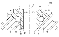
図13は、第4の実施形態における溶接後の接合体60Cの断面図である。
第4の実施形態の接合体60Cは、第1実施形態とは異なる形状のポンプボディ1Cと吐出ジョイント2Cと、これらを連結して溶接した環状溶接部6Cとを含んで構成される。環状溶接部6Cの断面は、円柱状空間5の径方向に対して斜めに傾斜している。
第4の実施形態の接合体60Cは、第1の実施形態の接合体60とは異なり、勘合部12がポンプボディ1に取り付けられている。このように、ポンプボディ1に勘合部12を形成した第4の実施形態についても、第1の実施形態と同様に、溶接の疲労強度を向上させることができる。
図13は、第4の実施形態における溶接後の接合体60Cの断面図である。
第4の実施形態の接合体60Cは、第1実施形態とは異なる形状のポンプボディ1Cと吐出ジョイント2Cと、これらを連結して溶接した環状溶接部6Cとを含んで構成される。環状溶接部6Cの断面は、円柱状空間5の径方向に対して斜めに傾斜している。
第4の実施形態の接合体60Cは、第1の実施形態の接合体60とは異なり、勘合部12がポンプボディ1に取り付けられている。このように、ポンプボディ1に勘合部12を形成した第4の実施形態についても、第1の実施形態と同様に、溶接の疲労強度を向上させることができる。
(第5の実施形態)
図14は、第5の実施形態における溶接前の接合体60Dの断面図である。
第5の実施形態の接合体60Dは、第1実施形態とは異なる形状のポンプボディ1Dと吐出ジョイント2Dとを含んで構成される。第5の実施形態の接合体60Dは、第1の実施形態の接合体60と異なり、突合せ面3近傍のポンプボディ表面11と吐出ジョイント表面21が円柱状空間5の中心軸に対して傾斜している。すなわち、突合せ面3よりポンプボディ1Dの側にいくにしたがって、ポンプボディ1Dの外径が大きくなる。反対に、突合せ面3より吐出ジョイント2D側にいくにしたがって吐出ジョイント2Dの外径が小さくなる。更に突合せ面3は、円柱状空間5の径方向に対して傾斜している。
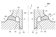
図15は、第5の実施形態における溶接後の断面図を示す。
第5の実施形態の接合体60Dは、第1実施形態とは異なる形状のポンプボディ1Dと吐出ジョイント2Dと、これらを連結して溶接した環状溶接部6Dとを含んで構成される。環状溶接部6Dの断面は、円柱状空間5の径方向に対して斜めに傾斜している。
第5の実施形態においても、第1の実施形態と同様に、環状溶接部6Dの疲労強度の向上させることができる。特に、第5の実施形態では環状溶接部6D近傍においてポンプボディ1Dを厚くできるので、第1の実施形態よりも疲労強度の向上には有効である。
第5の実施形態の接合体60Dは、第1実施形態とは異なる形状のポンプボディ1Dと吐出ジョイント2Dと、これらを連結して溶接した環状溶接部6Dとを含んで構成される。環状溶接部6Dの断面は、円柱状空間5の径方向に対して斜めに傾斜している。
第5の実施形態においても、第1の実施形態と同様に、環状溶接部6Dの疲労強度の向上させることができる。特に、第5の実施形態では環状溶接部6D近傍においてポンプボディ1Dを厚くできるので、第1の実施形態よりも疲労強度の向上には有効である。
(変形例)
本発明は上記した実施形態に限定されるものではなく、様々な変形例が含まれる。例えば上記した実施形態は、本発明を分かりやすく説明するために詳細に説明したものであり、必ずしも説明した全ての構成を備えるものに限定されるものではない。ある実施形態の構成の一部を他の実施形態の構成に置き換えることが可能であり、ある実施形態の構成に他の実施形態の構成を加えることも可能である。また、各実施形態の構成の一部について、他の構成の追加・削除・置換をすることも可能である。
本発明の変形例として、例えば、次の(a)~(d)のようなものがある。
(a) 上記実施形態の接合体は、燃料供給ポンプ10に限られず、任意のポンプに用いられていてもよい。
(b) 上記実施形態の接合体は、ポンプボディ1Dと吐出ジョイント2Dとの溶接に限られず、ポンプボディ1Dと容量制御ジョイント9との溶接に対して適用してもよい。
(c) 容量制御ジョイント9のように、内部に円柱状空間5が形成されていないものを第2部材としてもよい。
(d) 接合体の内部の空間は、円柱状に限られず、楕円形状、多角柱状など任意の形状でもょい。
1,1A~1D ポンプボディ (第1部材の一例)
10 燃料供給ポンプ
11 ポンプボディ表面
12 勘合部
13 環状面
14 平面
15 本体
16 筒部
2,2A~2D 吐出ジョイント (第2部材の一例)
21 吐出ジョイント表面
22 勘合部
23 環状面
24 平面
26 吐出弁機構
3 突合せ面
31 勘合面
4 環状空間
5 円柱状空間
51 スパッタカバー
6,6A,6D 環状溶接部
60 接合体
61 内周側曲面
61s 溶接裏面
62 外周側曲面
62s 溶接表面
7 吸入ジョイント
71 ダンパー
72 ダンパーホルダ
8 ピストンプランジャー
81 シリンダ
82 シリンダホルダ
83 加圧室
9 容量制御ジョイント (第2部材の一例)
91 突合せ面
92 電磁バルブ
93 電磁コイル
94 バネ
95 吸入弁体
L レーザ光
Claims (14)
- 媒体の圧力が作用する空間が内部に形成された第1部材と、
前記第1部材に嵌め合う第2部材と、
前記空間の外周側に設けられ、前記第1部材と前記第2部材とを溶接して連結する環状溶接部を備え、
前記環状溶接部は、当該環状溶接部の内周側の前記第1部材との境界と前記第2部材との境界とを結ぶ内周側曲面の垂線に対して、所定角だけ傾斜して形成されている、
ことを特徴とする接合体。 - 前記環状溶接部の外周側の前記第1部材との境界と前記第2部材との境界とを結ぶ外周側曲面の中央は、前記内周側曲面の中央に対して前記空間の軸線方向にずれている、
ことを特徴とする請求項1に記載の接合体。 - 前記環状溶接部の前記内周側曲面の垂線に対する前記環状溶接部の傾斜は、10°から50°の間である、
ことを特徴とする請求項1に記載の接合体。 - 前記空間と前記環状溶接部との間には、前記第2部材から突出して前記第1部材に勘合する勘合部と、前記勘合部の外周側に前記第1、第2部材の環状の窪みにより環状空間が形成されており、
前記環状空間は、前記勘合部により前記空間から分離される、
ことを特徴とする請求項1に記載の接合体。 - 前記第2部材の表面と前記環状溶接部の表面との境界における厚みよりも前記第1部材の表面と前記環状溶接部との境界における厚みの方が大きい、
ことを特徴とする請求項1に記載の接合体。 - 前記環状溶接部の内周面は、前記第1、第2部材の窪み部分が溶融凝固して形成される、
ことを特徴とする請求項5に記載の接合体。 - 燃料の圧力が作用する空間が内部に形成された第1部材と、
前記第1部材に嵌め合う第2部材と、
前記空間の外周側に設けられ、前記第1部材と前記第2部材とを溶接して連結する環状溶接部を備える接合体を用いており、
前記環状溶接部は、当該環状溶接部の内周側の前記第1部材との境界と前記第2部材との境界とを結ぶ内周側曲面の垂線に対して、所定角だけ傾斜して形成されている、
ことを特徴とする燃料供給ポンプ。 - 前記環状溶接部の軸方向の断面において、前記環状溶接部の内周側の前記第1部材との境界と前記第2部材との境界とを結ぶ内周線の垂線に対し、前記環状溶接部の内周側幅方向の中心点と前記環状溶接部の外周側幅方向の中心点とを結ぶ直線が所定角だけ傾斜している、
ことを特徴とする請求項7に記載の燃料供給ポンプ。 - 前記第1部材は、ポンプボディであり、
前記第2部材は、吐出ジョイントである、
ことを特徴とする請求項8に記載の燃料供給ポンプ。 - 前記環状溶接部の断面において、前記環状溶接部の前記内周線の垂線に対し、前記環状溶接部の内周側幅方向の中心点と前記環状溶接部の外周側幅方向の中心点とを結ぶ直線が、外周側では前記吐出ジョイント側に傾斜し、内周側では前記ポンプボディ側に傾斜している、
ことを特徴とする請求項9に記載の燃料供給ポンプ。 - 前記第2部材の表面と前記環状溶接部の表面との境界における厚みよりも前記第1部材の表面と前記環状溶接部との境界における厚みが大きい、
ことを特徴とする請求項9に記載の燃料供給ポンプ。 - 前記第1部材は、ポンプボディであり、
前記第2部材は、容量制御ジョイントである、
ことを特徴とする請求項8に記載の燃料供給ポンプ。 - 前記環状溶接部の断面において、前記環状溶接部の前記内周線の垂線に対し、前記環状溶接部の内周側幅方向の中心点と前記環状溶接部の外周側幅方向の中心点とを結ぶ直線が、外周側では前記容量制御ジョイント側に傾斜し、内周側では前記ポンプボディ側に傾斜している、
ことを特徴とする請求項12に記載の燃料供給ポンプ。 - 前記第2部材の表面と前記環状溶接部の表面との境界における厚みよりも前記第1部材の表面と前記環状溶接部との境界における厚みが大きい、
ことを特徴とする請求項12に記載の燃料供給ポンプ。
Applications Claiming Priority (2)
| Application Number | Priority Date | Filing Date | Title |
|---|---|---|---|
| JP2015-027619 | 2015-02-16 | ||
| JP2015027619A JP6463980B2 (ja) | 2015-02-16 | 2015-02-16 | 接合体および燃料供給ポンプ |
Publications (1)
| Publication Number | Publication Date |
|---|---|
| WO2016132896A1 true WO2016132896A1 (ja) | 2016-08-25 |
Family
ID=56692046
Family Applications (1)
| Application Number | Title | Priority Date | Filing Date |
|---|---|---|---|
| PCT/JP2016/053129 Ceased WO2016132896A1 (ja) | 2015-02-16 | 2016-02-03 | 接合体および燃料供給ポンプ |
Country Status (2)
| Country | Link |
|---|---|
| JP (1) | JP6463980B2 (ja) |
| WO (1) | WO2016132896A1 (ja) |
Cited By (2)
| Publication number | Priority date | Publication date | Assignee | Title |
|---|---|---|---|---|
| JP2018178969A (ja) * | 2017-04-21 | 2018-11-15 | 日立オートモティブシステムズ株式会社 | 高圧燃料供給ポンプ |
| JPWO2021235018A1 (ja) * | 2020-05-18 | 2021-11-25 |
Families Citing this family (1)
| Publication number | Priority date | Publication date | Assignee | Title |
|---|---|---|---|---|
| WO2018142930A1 (ja) * | 2017-01-31 | 2018-08-09 | 日立オートモティブシステムズ株式会社 | 高圧燃料供給ポンプ |
Citations (6)
| Publication number | Priority date | Publication date | Assignee | Title |
|---|---|---|---|---|
| JP2004354274A (ja) * | 2003-05-30 | 2004-12-16 | Ngk Spark Plug Co Ltd | ガスセンサ及びガスセンサの製造方法 |
| JP2005279778A (ja) * | 2004-03-30 | 2005-10-13 | Robert Bosch Gmbh | 肉厚の構成部材と肉薄の構成部材との間の溶接結合部ならびに内燃機関に用いられる燃料高圧ポンプ |
| JP2006090746A (ja) * | 2004-09-21 | 2006-04-06 | Ngk Spark Plug Co Ltd | 温度センサ及びその製造方法 |
| JP2011080391A (ja) * | 2009-10-06 | 2011-04-21 | Hitachi Automotive Systems Ltd | 高圧燃料供給ポンプの吐出弁機構 |
| JP2013169565A (ja) * | 2012-02-21 | 2013-09-02 | Hitachi Automotive Systems Ltd | レーザ溶接接合構造および方法、レーザ溶接接合構造を有する高圧燃料供給ポンプ |
| JP2014205184A (ja) * | 2013-04-16 | 2014-10-30 | 日立オートモティブシステムズ株式会社 | 重ね溶接継手、燃料噴射弁およびレーザ溶接方法 |
Family Cites Families (3)
| Publication number | Priority date | Publication date | Assignee | Title |
|---|---|---|---|---|
| JPH0259892U (ja) * | 1988-10-24 | 1990-05-01 | ||
| JP2002004979A (ja) * | 2000-06-20 | 2002-01-09 | Kawasaki Heavy Ind Ltd | 作動機構とこれを用いた弁装置 |
| JP5614054B2 (ja) * | 2010-02-22 | 2014-10-29 | 日産自動車株式会社 | ビーム溶接部材およびこれを備えた差動装置 |
-
2015
- 2015-02-16 JP JP2015027619A patent/JP6463980B2/ja not_active Expired - Fee Related
-
2016
- 2016-02-03 WO PCT/JP2016/053129 patent/WO2016132896A1/ja not_active Ceased
Patent Citations (6)
| Publication number | Priority date | Publication date | Assignee | Title |
|---|---|---|---|---|
| JP2004354274A (ja) * | 2003-05-30 | 2004-12-16 | Ngk Spark Plug Co Ltd | ガスセンサ及びガスセンサの製造方法 |
| JP2005279778A (ja) * | 2004-03-30 | 2005-10-13 | Robert Bosch Gmbh | 肉厚の構成部材と肉薄の構成部材との間の溶接結合部ならびに内燃機関に用いられる燃料高圧ポンプ |
| JP2006090746A (ja) * | 2004-09-21 | 2006-04-06 | Ngk Spark Plug Co Ltd | 温度センサ及びその製造方法 |
| JP2011080391A (ja) * | 2009-10-06 | 2011-04-21 | Hitachi Automotive Systems Ltd | 高圧燃料供給ポンプの吐出弁機構 |
| JP2013169565A (ja) * | 2012-02-21 | 2013-09-02 | Hitachi Automotive Systems Ltd | レーザ溶接接合構造および方法、レーザ溶接接合構造を有する高圧燃料供給ポンプ |
| JP2014205184A (ja) * | 2013-04-16 | 2014-10-30 | 日立オートモティブシステムズ株式会社 | 重ね溶接継手、燃料噴射弁およびレーザ溶接方法 |
Cited By (6)
| Publication number | Priority date | Publication date | Assignee | Title |
|---|---|---|---|---|
| JP2018178969A (ja) * | 2017-04-21 | 2018-11-15 | 日立オートモティブシステムズ株式会社 | 高圧燃料供給ポンプ |
| JPWO2021235018A1 (ja) * | 2020-05-18 | 2021-11-25 | ||
| WO2021235018A1 (ja) * | 2020-05-18 | 2021-11-25 | 日立Astemo株式会社 | 高圧燃料供給ポンプ |
| CN115552109A (zh) * | 2020-05-18 | 2022-12-30 | 日立安斯泰莫株式会社 | 高压燃料供给泵 |
| JP7284348B2 (ja) | 2020-05-18 | 2023-05-30 | 日立Astemo株式会社 | 高圧燃料供給ポンプ |
| CN115552109B (zh) * | 2020-05-18 | 2025-02-18 | 日立安斯泰莫株式会社 | 高压燃料供给泵 |
Also Published As
| Publication number | Publication date |
|---|---|
| JP2016151185A (ja) | 2016-08-22 |
| JP6463980B2 (ja) | 2019-02-06 |
Similar Documents
| Publication | Publication Date | Title |
|---|---|---|
| JP5322074B2 (ja) | 肉厚の構成部材と肉薄の構成部材との間の溶接結合部ならびに内燃機関に用いられる燃料高圧ポンプ | |
| JP2012215164A (ja) | 高圧ポンプ | |
| JP6463980B2 (ja) | 接合体および燃料供給ポンプ | |
| JP6611544B2 (ja) | 接合体、流体圧シリンダ、及び接合体の製造方法 | |
| WO2017022603A1 (ja) | ダイアフラムダンパ | |
| JP5861900B2 (ja) | 高圧ポンプ | |
| JP5604212B2 (ja) | 電磁式駆動ユニットおよびその製造方法 | |
| JP6940569B2 (ja) | 高圧燃料ポンプ | |
| JP6734941B2 (ja) | 高圧燃料供給ポンプ | |
| KR102556113B1 (ko) | 고압 연료 펌프 | |
| JP5771545B2 (ja) | レーザ溶接接合構造および方法、レーザ溶接接合構造を有する高圧燃料供給ポンプ | |
| JP2016515681A (ja) | ピストンポンプ、特に高圧燃料ポンプ | |
| JP2012057577A (ja) | 軸付回転体 | |
| CN101592111B (zh) | 燃料喷射阀和焊接方法 | |
| JP5178676B2 (ja) | 高圧燃料供給ポンプ | |
| JP5327071B2 (ja) | 高圧ポンプ | |
| JPWO2019102983A1 (ja) | メタルダイアフラムダンパ及びその製造方法 | |
| JP2011220199A (ja) | ダンパ部材の製造方法 | |
| CN106439150A (zh) | 阀的壳体组件及阀 | |
| JP2023173797A (ja) | 溶接方法及び燃料ポンプの溶接方法 | |
| WO2020255524A1 (ja) | 接手構造及びこれを用いた高圧燃料供給ポンプ | |
| JP7502476B2 (ja) | 2部品の接合物及びその製造方法 | |
| JP6938101B2 (ja) | 高圧燃料供給ポンプ及び高圧燃料供給ポンプの製造方法 | |
| JP6234839B2 (ja) | デリバリパイプ | |
| JP6648808B2 (ja) | 高圧ポンプ |
Legal Events
| Date | Code | Title | Description |
|---|---|---|---|
| 121 | Ep: the epo has been informed by wipo that ep was designated in this application |
Ref document number: 16752283 Country of ref document: EP Kind code of ref document: A1 |
|
| NENP | Non-entry into the national phase |
Ref country code: DE |
|
| 122 | Ep: pct application non-entry in european phase |
Ref document number: 16752283 Country of ref document: EP Kind code of ref document: A1 |