WO2016132867A1 - リアクトル - Google Patents
リアクトル Download PDFInfo
- Publication number
- WO2016132867A1 WO2016132867A1 PCT/JP2016/052755 JP2016052755W WO2016132867A1 WO 2016132867 A1 WO2016132867 A1 WO 2016132867A1 JP 2016052755 W JP2016052755 W JP 2016052755W WO 2016132867 A1 WO2016132867 A1 WO 2016132867A1
- Authority
- WO
- WIPO (PCT)
- Prior art keywords
- core
- sealing resin
- case
- reactor
- core pieces
- Prior art date
- Legal status (The legal status is an assumption and is not a legal conclusion. Google has not performed a legal analysis and makes no representation as to the accuracy of the status listed.)
- Ceased
Links
Images

Classifications
-
- H—ELECTRICITY
- H01—ELECTRIC ELEMENTS
- H01F—MAGNETS; INDUCTANCES; TRANSFORMERS; SELECTION OF MATERIALS FOR THEIR MAGNETIC PROPERTIES
- H01F27/00—Details of transformers or inductances, in general
- H01F27/02—Casings
- H01F27/022—Encapsulation
-
- H—ELECTRICITY
- H01—ELECTRIC ELEMENTS
- H01F—MAGNETS; INDUCTANCES; TRANSFORMERS; SELECTION OF MATERIALS FOR THEIR MAGNETIC PROPERTIES
- H01F27/00—Details of transformers or inductances, in general
- H01F27/24—Magnetic cores
-
- H—ELECTRICITY
- H01—ELECTRIC ELEMENTS
- H01F—MAGNETS; INDUCTANCES; TRANSFORMERS; SELECTION OF MATERIALS FOR THEIR MAGNETIC PROPERTIES
- H01F27/00—Details of transformers or inductances, in general
- H01F27/24—Magnetic cores
- H01F27/26—Fastening parts of the core together; Fastening or mounting the core on casing or support
- H01F27/263—Fastening parts of the core together
-
- H—ELECTRICITY
- H01—ELECTRIC ELEMENTS
- H01F—MAGNETS; INDUCTANCES; TRANSFORMERS; SELECTION OF MATERIALS FOR THEIR MAGNETIC PROPERTIES
- H01F27/00—Details of transformers or inductances, in general
- H01F27/28—Coils; Windings; Conductive connections
- H01F27/30—Fastening or clamping coils, windings, or parts thereof together; Fastening or mounting coils or windings on core, casing, or other support
- H01F27/306—Fastening or mounting coils or windings on core, casing or other support
-
- H—ELECTRICITY
- H01—ELECTRIC ELEMENTS
- H01F—MAGNETS; INDUCTANCES; TRANSFORMERS; SELECTION OF MATERIALS FOR THEIR MAGNETIC PROPERTIES
- H01F3/00—Cores, Yokes, or armatures
- H01F3/10—Composite arrangements of magnetic circuits
- H01F3/14—Constrictions; Gaps, e.g. air-gaps
-
- H—ELECTRICITY
- H01—ELECTRIC ELEMENTS
- H01F—MAGNETS; INDUCTANCES; TRANSFORMERS; SELECTION OF MATERIALS FOR THEIR MAGNETIC PROPERTIES
- H01F37/00—Fixed inductances not covered by group H01F17/00
-
- H—ELECTRICITY
- H01—ELECTRIC ELEMENTS
- H01F—MAGNETS; INDUCTANCES; TRANSFORMERS; SELECTION OF MATERIALS FOR THEIR MAGNETIC PROPERTIES
- H01F41/00—Apparatus or processes specially adapted for manufacturing or assembling magnets, inductances or transformers; Apparatus or processes specially adapted for manufacturing materials characterised by their magnetic properties
- H01F41/005—Impregnating or encapsulating
-
- H—ELECTRICITY
- H01—ELECTRIC ELEMENTS
- H01F—MAGNETS; INDUCTANCES; TRANSFORMERS; SELECTION OF MATERIALS FOR THEIR MAGNETIC PROPERTIES
- H01F41/00—Apparatus or processes specially adapted for manufacturing or assembling magnets, inductances or transformers; Apparatus or processes specially adapted for manufacturing materials characterised by their magnetic properties
- H01F41/02—Apparatus or processes specially adapted for manufacturing or assembling magnets, inductances or transformers; Apparatus or processes specially adapted for manufacturing materials characterised by their magnetic properties for manufacturing cores, coils, or magnets
- H01F41/0206—Manufacturing of magnetic cores by mechanical means
Definitions
- the present invention relates to a reactor used for a vehicle-mounted DC-DC converter or a power converter component mounted on a vehicle such as a hybrid vehicle.
- Patent Document 1 discloses a reactor used for a circuit component of an in-vehicle converter.
- a coil formed by winding a winding, an annular magnetic core in which the coil is disposed, a case housing a combination of the coil and the magnetic core, and the coil and the magnetic core
- a case storage type reactor including an interposed insulator and a sealing resin filled in the case.
- an adhesive or an adhesive tape is described for the integration of a plurality of core pieces constituting the magnetic core and the integration of the core pieces and the gap material.
- the present invention has been made in view of the above circumstances, and one of the objects of the present invention is to provide a reactor that can easily hold components in a predetermined position in the manufacturing process and is excellent in productivity.
- the reactor which concerns on 1 aspect of this invention combines the coil which has a winding part, the gap material interposed between several core pieces and each core piece, and has the magnetic part which has a part arrange
- An intermediate member interposed between the core and the inner surface of the winding portion and the magnetic core, and having a core holding portion for positioning each core piece while ensuring a space between the plurality of core pieces;
- a case that houses a combination of the coil, the magnetic core, and the interposition member; and a sealing resin portion that fills the case and seals the combination.
- the gap material is formed of a constituent resin of the sealing resin portion.
- the reactor described above is easy to hold in a predetermined position between the constituent members in the manufacturing process, and is excellent in productivity.
- FIG. 1 is a schematic perspective view of a reactor according to a first embodiment.
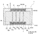
- FIG. 2 is a (II)-(II) cross-sectional view of the reactor of FIG.
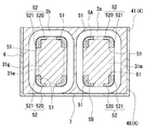
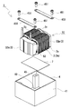
- FIG. 3 is a (III)-(III) cross-sectional view of the reactor of FIG. 1 is a schematic exploded perspective view of a reactor according to a first embodiment.
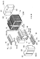
- FIG. 3 is a schematic exploded perspective view of an assembly provided in the reactor according to the first embodiment.
- the reactor which concerns on embodiment of this invention combines the coil which has a winding part, several core pieces, and the gap material interposed between each core piece, and the part arrange
- the gap material is formed of a constituent resin of the sealing resin portion.
- the above-mentioned reactor can ensure the relative positioning of each core piece by securing the interval between adjacent core pieces by the interposition member. Since the core piece to which the interposition member is attached can be handled as an integrated object with a gap between the core pieces, the workability is excellent. By inserting the core piece fitted with the interposition member into the winding part, each core piece can maintain a state having a gap between the core pieces in the winding part. Therefore, when the assembly is placed in the case, and the unsolidified constituent resin of the sealing resin portion is filled in the case, the unsolidified constituent resin flows into the gaps between the core pieces, and between the core pieces. A gap material corresponding to the interval is formed.
- the assembly of the coil, the magnetic core, and the interposition member can be sealed, and a gap material between each core piece can be formed. It is possible to simplify the work of fixing with a glue or the like, and the reactor productivity is excellent.
- the interposed member is formed on the support portion that supports the core holding portion and the support portion, and when the sealing resin portion is molded, And a flow path for allowing unsolidified constituent resin to flow between the plurality of core pieces.
- the flow path is formed in the support portion connected to the core holding portion that secures the interval between the plurality of core pieces, and the unsolidified up to the gap between the core pieces along the flow path.
- the constituent resin can be reliably introduced. Therefore, it is easy to form the gap material with the constituent resin of the sealing resin portion between the core pieces.
- the sealing resin portion may be formed of a soft resin.
- the magnetic core vibrates due to repeated expansion and contraction due to magnetostriction and generates noise. For example, a transmission sound is generated when the vibration of the magnetic core is transmitted to the case.
- the sealing resin portion is made of a soft resin, the vibration of the magnetic core is buffered by the sealing resin portion. Therefore, it can suppress that the vibration of a magnetic core is transmitted to a case, and can suppress the vibration transmission sound from a magnetic core to a case.
- the gap material interposed between the core pieces is formed of the constituent resin of the sealing resin portion, so that the vibration of the magnetic core (each core piece) can be more easily buffered. The effect of suppressing vibrations from being transmitted to the case is high.
- the sealing resin portion is made of a soft resin
- an outer core piece disposed outside the winding portion of the magnetic core and the outer core piece are placed.
- a gap is provided between the case and the mounting surface of the case, and the sealing resin portion is filled up to the gap.
- a sealing resin portion made of a soft resin is interposed between the outer core piece and the mounting surface of the case, so that direct contact between the magnetic core and the case is avoided, and the vibration of the magnetic core is sealed with the sealing resin. Since it can buffer by a part, vibration transmission of a magnetic core to a case can further be controlled.
- the sealing resin portion may be formed of a hard resin.
- the sealing resin portion is made of a hard resin, the magnetic core is firmly sealed by the sealing resin portion. Therefore, vibration of the magnetic core itself can be suppressed.
- the gap material interposed in each core piece is formed of the constituent resin of the sealing resin portion, so that the effect of suppressing the vibration of the magnetic core (each core piece) itself is high.
- the reactor 1 includes a coil 2 having winding portions 2a and 2b formed by winding a winding 2w in a spiral shape, and winding portions 2a and 2b.
- a magnetic core 3 having a portion disposed therein, an interposition member 5 interposed between the inner surfaces of the winding portions 2a and 2b and the magnetic core 3, and a combination of the coil 2, the magnetic core 3 and the interposition member 5
- a case 4 that houses the body 10 and a sealing resin portion 6 that is filled in the case 4 and seals the combined body 10 are provided.
- the magnetic core 3 includes a plurality of inner core pieces 31m,...
- the gap member 31g includes a core holding portion 51 (see FIG. 3) in which the interposition member 5 secures intervals between the plurality of core pieces and positions each core piece.
- the sealing resin portion 6 is formed of a constituent resin (see FIGS. 2 and 3).
- the coil 2 includes a pair of cylindrical winding portions 2a and 2b formed by spirally winding a single continuous winding 2w, and both winding portions 2a, A connecting portion 2r for connecting 2b.
- Each winding part 2a, 2b is formed in a hollow cylinder shape with the same number of turns and the same winding direction, and is arranged in parallel (side by side) so that the respective axial directions are parallel.
- the connecting portion 2r is a portion bent in a U shape that connects the winding portions 2a and 2b.
- the coil 2 may be formed by spirally winding a single winding without a joint.
- the windings 2a and 2b may be formed by separate windings, and the windings 2a and 2b You may form by joining the edge parts of a coil
- Each winding part 2a, 2b of this embodiment is formed in a rectangular tube shape.
- the rectangular cylindrical winding parts 2a and 2b are winding parts having rounded corners whose end face shape is a quadrangle (including a square shape).
- the winding portions 2a and 2b may be formed in a cylindrical shape.
- the cylindrical winding portion is a winding portion whose end face shape is a closed curved surface shape (an elliptical shape, a perfect circle shape, a race track shape, etc.).
- the coil 2 including the winding portions 2a and 2b is a coated wire having an insulating coating made of an insulating material on the outer periphery of a conductor such as a flat wire or a round wire made of a conductive material such as copper, aluminum, magnesium, or an alloy thereof. Can be configured.
- the winding portions 2a and 2b are formed by edgewise winding a rectangular wire made of copper and a conductor made of enamel (typically polyamideimide). Yes.
- the magnetic core 3 includes a plurality of columnar inner core pieces 31m,..., A pair of U-shaped outer core pieces 32m, 32m, and a plurality of intervening core pieces. (See FIG. 2).
- the inner core pieces 31m,... Are magnetic pieces that are entirely disposed within the winding portions 2a, 2b, and the outer core pieces 32m, 32m are magnetic pieces having portions that are disposed outside the winding portions 2a, 2b. That is.
- the outer core pieces 32m and 32m may have a portion partially disposed in the winding portions 2a and 2b. In this example, the outer core pieces 32m and 32m are outside the winding portions 2a and 2b.
- the outer core pieces 32m, 32m are arranged so that the U-shaped openings face each other, and the inner core pieces 31m,... Are arranged side by side (in parallel) between the outer core pieces 32m, 32m.
- the gap material between the inner core pieces 31m, 31m is filled with a constituent resin of the sealing resin portion 6 to be described later, so that a gap material is obtained.
- 31g,... See FIG. 2 are formed.
- the gap resin 31g is also formed by filling the gap between the inner core piece 31m and the outer core piece 32m opposite thereto with the constituent resin of the sealing resin portion 6.
- the inner core piece 31m preferably has a shape that matches the shape of the winding portions 2a and 2b.
- the shape of the inner core piece 31m is a rectangular parallelepiped shape, and the corners thereof are rounded along the corners of the inner peripheral surfaces of the winding portions 2a and 2b.
- the number of inner core pieces 31m can be selected as appropriate.
- the pair of outer core pieces 32m, 32m have the same shape and are substantially U-shaped when viewed from above in FIG.
- the outer core piece 32m is a rectangular parallelepiped outer core base 321 disposed outside the winding portions 2a and 2b and straddling between the winding portions 2a and 2b, and is wound around the outer core base 321.
- a pair of protrusions 322 disposed in the portions 2a and 2b, respectively.
- the outer core base portion 321 and the pair of projecting portions 322 and 322 are integrally formed. Further, here, the outer core base 321 is integrally formed with a portion protruding to the opposite side of the pair of protruding portions 322 and 322.
- the cross-sectional area of the protruding portion is substantially the same as the cross-sectional area of the inner core piece 31m and the protruding portion 322.
- the end surfaces of the pair of projecting portions 322 and 322 have substantially the same shape and size as the end surface of the inner core piece 31m, and the size and projecting length have a predetermined magnetic path cross-sectional area corresponding to the coil 2. As appropriate, it can be selected.
- the pair of protrusions 322 and 322 preferably have a shape that matches the shape of the winding portions 2a and 2b.
- the corners are substantially at the corners of the inner peripheral surfaces of the winding portions 2a and 2b. Rounded along.
- the lower surface of the outer core base 321 in the U-shaped outer core pieces 32m, 32m protrudes from the lower surface of the inner core piece 31m.
- the lower surface of the coil 2 protrudes from the lower surface of the outer core base portion 321, and the lower surface of the outer core base portion 321 and a bottom plate portion 40 of the case 4 to be described later are mounted.
- a gap is formed between the mounting surface (see FIG. 2).
- the height of the outer core base 321 is adjusted so that the gap is formed.
- a gap between the lower surface of the outer core base 321 and the bottom plate portion 40 of the case 4 is, for example, 0.3 mm or more and 3.0 mm or less.
- the lower surface of the coil 2 protrudes from the lower surface of the outer core base portion 321.
- the lower surface and the lower surface of the outer core base 321 may be flush with each other.
- a bonding layer 7 to be described later is interposed between the lower surface of the coil 2 and the bottom plate portion 40, so that the thickness between the lower surface of the outer core base 321 and the bottom plate portion 40 depends on the thickness of the bonding layer 7. A gap is formed.
- both the inner core piece 31m and the outer core piece 32m are compacted bodies.
- the green compact is typically a raw powder containing a soft magnetic metal powder such as iron or an iron alloy (Fe—Si alloy, Fe—Ni alloy, etc.) and a binder (resin etc.) or a lubricant as appropriate. After being molded, it is obtained by performing a heat treatment for the purpose of removing distortion associated with the molding.
- a coating powder obtained by subjecting a metal powder to insulation treatment, or a mixed powder obtained by mixing a metal powder and an insulating material the metal powder and the insulating material interposed between the metal particles after forming are substantially used.
- a compacted green body is obtained. Since this compacting body contains an insulating material, eddy current can be reduced and the loss is low.
- the gap material 31g is formed by filling a gap formed between the core pieces with a constituent resin of the sealing resin portion 6 described later.
- the gap material 31g will be described in detail later in the description of the reactor manufacturing method.
- the interposition member 5 is interposed between the inner surface of the winding portions 2a and 2b and the core portion disposed in the winding portions 2a and 2b of the magnetic core 3, and the coil 2 and the magnetic core 3 It is a member that insulates the gap.
- a pair of interposition members 5 and 5 are provided, which are individually arranged for each of the winding portions 2a and 2b. Since a pair of interposition members 5 and 5 are the same shape, below, one interposition member 5 arrange
- the interposition member 5 is composed of a pair of split interposition members 5A and 5B having a split surface along the axial direction of the winding portion.
- each configuration of the interposition member 5 will be described in detail mainly with reference to FIGS.
- Each of the pair of divided interposing members 5A and 5B is configured by a cross-section] body, is not in contact with each other, and is disposed in a part of the circumferential direction of the inner core pieces 31m (see FIGS. 3 and 5). ).
- each divided interposing member 5A, 5B extends over the entire length in the axial direction of the plurality of inner core pieces 31m,. It has a length to be arranged (see FIGS. 2 and 5).
- the pair of divided interposing members 5A and 5B are arranged so as to be sandwiched from the upper surface and the lower surface of the inner core pieces 31m.
- the divided interposing member 5A (5B) includes a top plate portion 520 disposed on the entire upper surface (lower surface) of the projecting portions 322 and 322 of the inner core piece 31m, ... and the outer core piece 32m, and the top plate portion 520. And a pair of leg portions 521 and 521 arranged from the corners of the protruding portions 322 and 322 of the outer core piece 32m to a part of the side surface.
- a plurality of core holding portions 51,... Protruding inward are integrally formed on the inner surfaces of the top plate portion 520 and the leg portions 521, 521. That is, the top plate portion 520 and the leg portions 521 and 521 serve as a support portion 52 that supports the core holding portion 51.
- Each of the core holding portions 51 has an I-shaped protrusion extending from the corner portion formed by the top plate portion 520 and the leg portion 521 along the leg portion 521.
- the core holding portions 51 are interposed at the four corners of the gap between the inner core pieces 31m.
- a region surrounded by a dotted line corresponds to the cross-sectional area of the inner core piece 31m.
- Each core holding part 51, ... is shaped so that each inner core piece 31m, ... can be placed at a desired position.
- the thickness of the core holding portion 51 corresponds to the thickness of the gap material 31g (see FIG. 2). Therefore, when the pair of split interposed members 5A, 5B are arranged so that the core holding portions 51, ... are interposed between the inner core pieces 31m, ..., the inner core pieces 31m, ... can be positioned.
- a gap corresponding to the thickness of the gap material 31g can be formed between the inner core pieces 31m and 31m. That is, by sandwiching the inner core pieces 31m,... Between the pair of divided interposing members 5A, 5B, the core of the portion of the magnetic core 3 disposed in the winding portion can be accurately positioned.
- Each of the core holding portions 51,... Is formed such that the cross-sectional area of the gap material 31g formed by the constituent resin of the sealing resin portion 6 is 50% or more of the cross-sectional area of the inner core piece 31m. (See FIG. 3, the region surrounded by the dotted line in FIG. 3 corresponds to the cross-sectional area of the inner core piece 31m).
- the interval between the inner core pieces 31m,... Is more stable and easier to secure as the contact area between the inner core piece 31m or the protruding portion 322 and the core holding portion 51 increases.
- the protruding area of the core holding part 51 is increased in order to increase the contact area between the inner core piece 31m or the protruding part 322 and the core holding part 51, the cross-sectional area of the gap between the core pieces is reduced. If it does so, the filling amount of the unsolidified constituent resin of the sealing resin part 6 with which it fills between each core piece will decrease, and the cross-sectional area of the gap material 31g formed with the constituent resin of the sealing resin part 6 will become small.
- the filling amount of the unsolidified constituent resin of the sealing resin portion 6 filled between the core pieces decreases, the area where the core pieces are fixed by the sealing resin portion 6 is reduced. Cannot be firmly fixed, and each core piece may vibrate when the reactor 1 operates.
- each gap can be secured so that the space between the core pieces can be secured, and the cross-sectional area of the gap material 31g formed by the constituent resin of the sealing resin portion 6 is 50% or more of the cross-sectional area of the inner core piece 31m. It is preferable to adjust the protruding amount of the core holding portions 51,.
- the cross-sectional area of the gap material 31g formed by the constituent resin of the sealing resin portion 6 is 60% or more, further 70% or more, particularly 80% or more of the cross-sectional area of the inner core piece 31m.
- the sealing resin portion 6 described later is filled into the case 4 in the top plate portion 520, the unsolidified constituent resin of the sealing resin portion 6 is placed between the inner core pieces 31m and 31m.
- a flow path 53 is formed to flow into the gap.
- a plurality of through holes 53h,... are formed in the top plate portion 520 so that the gaps between the inner core pieces 31m, 31m are exposed.
- the through-holes 53h Since the unsolidified constituent resin filled in the case 4 is normally filled from the lower side of the case 4 in order to suppress inclusion of bubbles, the through-holes 53h,. It is preferable to be formed on the split interposition member 5B disposed on the lower surface side of. Further, by providing the through hole 53h, it is possible to deaerate from the through hole 53h when the unsolidified constituent resin is filled.
- a groove (not shown) can be formed on the inner peripheral surface or the outer peripheral surface of the top plate portion 520 or the leg portion 521.
- a groove (not shown) can be formed on the inner peripheral surface or the outer peripheral surface of the top plate portion 520 or the leg portion 521.
- segmentation interposed member 5A, 5B toward the inner side of the axial direction of a winding part is mentioned.
- forming a lateral groove portion connecting the through holes 53h can be mentioned. By doing so, the unsolidified constituent resin of the sealing resin portion 6 is likely to flow into between the inner core pieces 31m.
- the constituent material of the interposition member 5 examples include polyphenylene sulfide (PPS) resin, polytetrafluoroethylene (PTFE) resin, liquid crystal polymer (LCP), nylon 6 and nylon 66, polyamide (PA) resin, polybutylene terephthalate (PBT), and the like.
- PPS polyphenylene sulfide
- PTFE polytetrafluoroethylene
- LCP liquid crystal polymer
- PA polyamide
- PBT polybutylene terephthalate
- Resin and thermoplastic resins such as acrylonitrile / butadiene / styrene (ABS) resin can be used.
- thermosetting resins such as unsaturated polyester resins, epoxy resins, urethane resins, and silicone resins can be used.
- the interposition member 5 can be easily manufactured by a known molding method such as injection molding of the above resin.
- the interposition member 5 has the pair of split interposition members 5A and 5B arranged independently of each other, but a fixing member for fixing the arrangement of the pair of split interposition members 5A and 5B may be provided.
- the interposing members 5A and 5B are fixed to the core piece with an adhesive tape.
- an adhesive tape is used for fixing the divided interposing members 5A and 5B, it is possible to avoid complication of the shape of the interposing member 5 and an increase in constituent materials, and it is excellent in workability because it can be fixed by a simple operation of attaching the adhesive tape.
- a fitting part that fits each other may be provided in the pair of divided interposing members 5A and 5B, or may be bound by a rubber band or a binding band.
- the interposition member 5 is arranged in a part of the circumferential direction of the inner core pieces 31m,... But may be arranged along the entire circumference of the inner core pieces 31m,.
- the interposition member 5 is only required to secure a space between the inner core pieces 31m,...
- the interposition member 5 is arranged in a part in the circumferential direction of the inner core pieces 31m,. The material can be reduced.
- the interposed member 5 has the same shape as the pair of divided interposed members 5A and 5B, but may have different shapes.
- the case 4 has a flat bottom plate portion 40 on which the combined body 10 is placed, and a substantially rectangular frame shape standing from the bottom plate portion 40 so as to surround the combined body 10.
- the side wall portion 41 has a substantially rectangular box shape on the side opposite to the bottom plate portion 40 (upper side).
- the reactor 1 can be protected from the external environment (dust, corrosion, etc.) and mechanical protection of the combination 10 by housing the combination 10 in the case 4.
- the bottom surface of the bottom plate portion 40 of the case 4 is fixed so as to contact the upper surface of an installation target (not shown) such as a cooling base, and the reactor 1 is installed on the installation target.
- FIG. 1 shows an installation state in which the bottom plate portion 40 is downward, there may be an installation state in which the bottom plate portion 40 is upward or sideward.
- the case 4 shown in this example is a metal case in which the bottom plate portion 40 and the side wall portion 41 are integrally formed.
- metal since metal has a relatively high thermal conductivity, if it is a metal case, the entire case can be used as a heat dissipation path, and heat generated in the assembly 10 can be efficiently applied to an external installation target (for example, a cooling base). Heat can be radiated well, and the heat dissipation of the reactor 1 can be improved.
- the constituent material of the case 4 include aluminum and its alloys, magnesium and its alloys, copper and its alloys, silver and its alloys, iron and austenitic stainless steel. When formed of aluminum, magnesium, or an alloy thereof, the case 4 can be lightened.
- the case 4 shown in this example is provided with stay mounting portions 45 at the four corners of the case 4. Then, the stays 450, 450 are arranged so as to hang over the upper surface of the outer core base portion 321 in each outer core piece 32m, and the stays 450, 450 are fastened to the stay mounting portion 45 with screws 451, whereby the assembly 10 is fixed to the bottom plate portion.
- the assembled body 10 can be fixed to the case 4 while being pressed toward the 40 side.
- the reactor 1 shown in this example includes a bonding layer 7 on the installation surface of the assembly 10 as shown in FIGS.
- the bonding layer 7 is interposed between the lower surface of the coil 2 and the bottom plate portion 40 in the combined body 10.
- the constituent material of the bonding layer 7 includes an insulating resin, particularly a ceramic filler, and has excellent heat dissipation (for example, a thermal conductivity of 0.1 W / m ⁇ K or more, more preferably 1 W / m ⁇ K or more, particularly 2 W / m ⁇ K or more) is preferable.
- the resin include thermosetting resins such as epoxy resin, silicone resin, and unsaturated polyester, and thermoplastic resins such as PPS resin and LCP.
- the bonding layer 7 may be formed by using, for example, a sheet-like material, coating, or spraying.
- the sealing resin part 6 is a member which seals the assembly 10 with which the case 4 was filled and accommodated in the case 4, as shown in FIG.
- the sealing resin portion 6 is filled until the upper surface excluding both winding ends of the coil 2 in the combined body 10 is buried (see FIG. 2).
- the reactor 1 seals the combined body 10 with the sealing resin portion 6 to fix the combined body 10 to the case 4, and protects the combined body 10 from electrical and mechanical protection, protection from the external environment, and the coil 2. It is possible to reduce the vibration of the magnetic core 3 generated when energized and the noise caused by the vibration.
- the constituent resin of the sealing resin portion 6 is filled in the gaps between the core pieces 31m formed by the core holding portions 51 described above.
- a gap material 31g interposed between the core pieces is formed by the constituent resin of the sealing resin portion 6.
- an epoxy resin, a urethane resin, a silicone resin, an unsaturated polyester resin, or a PPS resin can be used as the constituent resin of the sealing resin portion 6.
- an epoxy resin and a urethane resin are preferable because they are soft and inexpensive.
- the sealing resin portion 6 may be mixed with a ceramic filler having high thermal conductivity such as alumina or silica.
- the constituent resin of the sealing resin portion 6 it is possible to use a soft resin.
- a soft resin for example, Young's modulus (20 to 100 ° C.), which is a kind of elastic modulus, can be 100 MPa or less. Since the sealing resin portion 6 is made of a soft resin, the vibration of the magnetic core 3 is buffered by the sealing resin portion 6. Therefore, since vibration transmission sound from the magnetic core 3 to the case 4 can be suppressed, it is easier to reduce noise caused by the vibration of the magnetic core 3.
- the gap members 31g,... Interposed between the core pieces 31m,... Are formed of the constituent resin of the sealing resin portion 6 so that the vibrations of the core pieces 31m,.
- the Young's modulus (20 to 100 ° C.) of this soft resin is further 20 MPa or less, particularly 5 MPa or less. If the Young's modulus of the soft resin is too low, the magnetic core 3 is likely to vibrate, so that it is 1 kPa or more, particularly 100 kPa or more.
- the Young's modulus of the constituent resin of the sealing resin portion 6 is a value obtained by measurement according to, for example, JIS K7161-2.
- a hard resin can be used as the constituent resin of the sealing resin portion 6.
- the Young's modulus (20 to 100 ° C.) which is a kind of elastic modulus, is 1 GPa or more. Since the sealing resin part 6 is made of a hard resin, the magnetic core 3 is firmly sealed by the sealing resin part 6. Therefore, vibration of the magnetic core 3 itself can be suppressed. In particular, since the gap members 31g,... Interposed between the core pieces 31m,... Are formed of the constituent resin of the sealing resin portion 6, vibrations of the core pieces 31m,.
- the Young's modulus (20 to 100 ° C.) of this hard resin is further 5 GPa or more, particularly 10 GPa or more.
- the reactor 1 having the above-described configuration includes, for example, a coil 2, a plurality of core pieces 31 m,... 32 m, 32 m and an interposition member 5 to form an assembly 10 ⁇ housing the assembly 10 in the case 4 ⁇ case 4
- the sealing resin portion 6 can be manufactured by a procedure of filling and solidifying an unsolidified constituent resin.
- a pair of outer core pieces 32m and 32m are assembled from both ends of the assembly to form an assembly 10.
- the outer core pieces 32m and 32m insert the projecting portions 322 and 322 into spaces formed at both ends of the pair of split interposed members 5A and 5B.
- the projecting portions 322 and 322 are in the winding portions 2a and 2b. 322 is arranged in a positioned state.
- the combined body 10 can be handled as an integral body in which the core pieces 31m,... 32m, 32m are positioned by the interposition member 5.
- the inner core pieces 31m,... Sandwiched between the pair of divided interposing members 5A, 5B are used as assemblies, and the pair of outer core pieces 32m, 32m are inserted into the assemblies and assembled.
- a U-shaped assembly in which each of the protruding portions 322 and 322 of the inner core piece 31m,... And one outer core piece 32m is sandwiched between a pair of divided interposing members 5A and 5B is manufactured.
- the other outer core piece 32m can also be assembled by inserting the coil 2 into the respective winding portions 2a and 2b from the opening side of the character.
- the assembly 10 is accommodated in the case 4 (refer FIG. 4).
- the bonding layer 7 is disposed on the lower surface of the combined body 10
- the combined body 10 is housed in the case 4.
- the stay 450 is disposed on the upper surface of the outer core base portion 321 of each of the outer core pieces 32m and 32m, and the stay 450 is fastened to the stay mounting portion 45 of the case 4 with screws 451, thereby fixing the combined body 10 in the case 4. To do.
- the unsolidified constituent resin of the sealing resin portion 6 is filled into the case 4 in which the combined body 10 is stored.
- the unsolidified constituent resin filled in the case 4 covers the outer periphery of the coil 2 and the outer periphery of the magnetic core 3, and reaches the gap between the coil 2 and the magnetic core 3.
- the unsolidified constituent resin flows along the flow path 53 provided in the interposition member 5 and fills in the gaps formed between the core pieces 31m,... 32m, 32m.
- the assembly 10 is sealed, and a gap material 31g between the core pieces 31m, ... 32m, 32m is formed.
- the reactor 1 described above seals the combined body 10 of the coil 2, the magnetic core 3, and the interposition member 5 during the molding of the sealing resin portion 6, and the gap material 31 g between the core pieces 31 m,. Can be formed. Therefore, it is possible to simplify the work of previously fixing the core piece and the gap material with an adhesive or the like as in the prior art, and the productivity of the reactor 1 is excellent.
- the reactor 1 can include a sensor (not shown) that measures the physical quantity of the reactor 1, such as a temperature sensor, a current sensor, a voltage sensor, and a magnetic flux sensor.
- the sensor can be arranged in a space formed between the two winding portions 2a and 2b.
- the reactor of the present invention includes various on-vehicle converters (typically DC-DC converters) mounted on vehicles such as hybrid vehicles, plug-in hybrid vehicles, electric vehicles, and fuel cell vehicles, and converters for air conditioners. It can utilize suitably for the component of a converter and a power converter device.
- DC-DC converters typically DC-DC converters mounted on vehicles such as hybrid vehicles, plug-in hybrid vehicles, electric vehicles, and fuel cell vehicles, and converters for air conditioners. It can utilize suitably for the component of a converter and a power converter device.
Landscapes
- Engineering & Computer Science (AREA)
- Power Engineering (AREA)
- Manufacturing & Machinery (AREA)
- Chemical & Material Sciences (AREA)
- Composite Materials (AREA)
- Dc-Dc Converters (AREA)
- Coils Of Transformers For General Uses (AREA)
Abstract
製造過程における構成部材同士の所定位置での保持が容易で、生産性に優れるリアクトルを提供する。巻回部を有するコイルと、複数のコア片及び各コア片間に介在されるギャップ材を組み合わせてなり、前記巻回部内に配置される部分を有する磁性コアと、前記巻回部の内面と前記磁性コアとの間に介在され、前記複数のコア片間の間隔を確保して、各コア片の位置決めを行うコア保持部を有する介在部材と、前記コイルと前記磁性コアと前記介在部材との組合体を収納するケースと、前記ケース内に充填され、前記組合体を封止する封止樹脂部と、を備え、前記ギャップ材は、前記封止樹脂部の構成樹脂によって形成されているリアクトル。
Description
本発明は、ハイブリッド自動車などの車両に搭載される車載用DC-DCコンバータや電力変換装置の構成部品などに利用されるリアクトルに関する。
リアクトルやモータといった磁性部品が種々の分野で利用されている。そのような磁性部品として、例えば特許文献1には、車載用コンバータの回路部品に利用されるリアクトルが開示されている。特許文献1には、巻線を巻回してなるコイルと、そのコイルが配置される環状の磁性コアと、コイルと磁性コアとの組合体を収納するケースと、コイルと磁性コアとの間に介在されるインシュレータと、ケース内に充填される封止樹脂と、を備えるケース収納タイプのリアクトルが開示されている。磁性コアを構成する複数のコア片同士の一体化やコア片とギャップ材との一体化には、例えば、接着剤や接着テープなどを利用することが記載されている。
近年、ハイブリッド自動車や電気自動車の需要が増す中、リアクトルの生産性を従来よりも向上させることが望まれている。このような要請に対して、ケース収納タイプのリアクトルは、その製造過程に改善の余地がある。
リアクトルの製造において、複数のコア片をコイルに組み付けてリアクトルを構成する際、各コア片同士の相対的な位置決めや、磁性コアとコイルとの相対的な位置決めに精度が求められる。そのため、特許文献1では、予めコア片とギャップ材とを接着テープなどで固定するなどして、磁性コアとコイルとの相対的な位置を精度良く決定している。このようなコア片とギャップ材との固定作業を簡略化することができれば、リアクトルの生産性を向上させることができると期待される。
本発明は上記事情に鑑みてなされたもので、本発明の目的の一つは、製造過程における構成部材同士の所定位置での保持が容易で、生産性に優れるリアクトルを提供することにある。
本発明の一態様に係るリアクトルは、巻回部を有するコイルと、複数のコア片及び各コア片間に介在されるギャップ材を組み合わせてなり、前記巻回部内に配置される部分を有する磁性コアと、前記巻回部の内面と前記磁性コアとの間に介在され、前記複数のコア片間の間隔を確保して、各コア片の位置決めを行うコア保持部を有する介在部材と、前記コイルと前記磁性コアと前記介在部材との組合体を収納するケースと、前記ケース内に充填され、前記組合体を封止する封止樹脂部と、を備える。前記ギャップ材は、前記封止樹脂部の構成樹脂によって形成されている。
上記のリアクトルは、製造過程における構成部材同士の所定位置での保持が容易で、生産性に優れる。
[本発明の実施形態の説明]
最初に、本発明の実施態様を列記して説明する。
最初に、本発明の実施態様を列記して説明する。
(1)本発明の実施形態に係るリアクトルは、巻回部を有するコイルと、複数のコア片及び各コア片間に介在されるギャップ材を組み合わせてなり、前記巻回部内に配置される部分を有する磁性コアと、前記巻回部の内面と前記磁性コアとの間に介在され、前記複数のコア片間の間隔を確保して、各コア片の位置決めを行うコア保持部を有する介在部材と、前記コイルと前記磁性コアと前記介在部材との組合体を収納するケースと、前記ケース内に充填され、前記組合体を封止する封止樹脂部と、を備える。前記ギャップ材は、前記封止樹脂部の構成樹脂によって形成されている。
上記のリアクトルは、介在部材によって、隣り合うコア片間の間隔を確保して、各コア片同士の相対的な位置決めを精度良くできる。介在部材を装着したコア片は、各コア片間に隙間を有した状態で一体物として取り扱えるため、作業性に優れる。この介在部材を装着したコア片を巻回部内に挿入することで、各コア片は、巻回部内で、各コア片間に隙間を有した状態を維持できる。そのため、組合体をケース内に配置して、封止樹脂部の未固化の構成樹脂をケース内に充填すると、この未固化の構成樹脂が上記コア片間の隙間に流入し、各コア片間の間隔に応じたギャップ材が形成される。この封止樹脂部の成形時に、コイルと磁性コアと介在部材との組合体を封止すると共に、各コア片間のギャップ材を形成できるため、リアクトルの製造過程において、予めコア片とギャップ材とを接着剤などで固定する作業を簡略化することができ、リアクトルの生産性に優れる。
(2)上記のリアクトルの一例として、前記介在部材は、前記コア保持部を支持する支持部と、前記支持部に形成され、前記封止樹脂部を成形する際に、前記封止樹脂部の未固化の構成樹脂を前記複数のコア片間まで流入させる流路と、を備える形態が挙げられる。
上記構成によれば、複数のコア片間の間隔を確保するコア保持部に繋がる支持部に流路が形成されていることで、この流路に沿って各コア片間の隙間まで上記未固化の構成樹脂を確実に流入させることができる。よって、各コア片間に封止樹脂部の構成樹脂でギャップ材を形成し易い。
(3)上記のリアクトルの一例として、前記封止樹脂部は、軟質性樹脂で構成されている形態が挙げられる。
リアクトルでは、コイルに所定周波数の電流が通電されて励磁されると、磁性コアが磁歪により伸縮を繰り返すことで振動して、騒音を発生する。例えば、磁性コアの振動がケースに伝達されることによる伝達音が発生する。封止樹脂部が軟質性樹脂で構成されていることで、磁性コアの振動が封止樹脂部により緩衝される。そのため、磁性コアの振動がケースに伝達されることを抑制でき、磁性コアからケースへの振動伝達音を抑制することができる。特に、上記のリアクトルでは、各コア片に介在されるギャップ材が封止樹脂部の構成樹脂によって形成されていることで、磁性コア(各コア片)の振動をより緩衝し易く、磁性コアの振動がケースに伝達されることを抑制する効果が高い。
(4)封止樹脂部が軟質性樹脂で構成されている上記のリアクトルの一例として、前記磁性コアのうち前記巻回部外に配置される外コア片と、前記外コア片が載置される前記ケースの載置面との間に隙間を有し、前記封止樹脂部は、前記隙間まで充填されている形態が挙げられる。
外コア片とケースの載置面との間に軟質性樹脂による封止樹脂部が介在されていることで、磁性コアとケースとの直接的な接触を避け、磁性コアの振動を封止樹脂部により緩衝することができるため、ケースへの磁性コアの振動伝達をさらに抑制できる。
(5)上記のリアクトルの一例として、前記封止樹脂部は、硬質性樹脂で構成されている形態が挙げられる。
封止樹脂部が硬質性樹脂で構成されていることで、磁性コアが封止樹脂部により強固に封止される。そのため、磁性コア自体の振動を抑制できる。特に、上記のリアクトルでは、各コア片に介在されるギャップ材が封止樹脂部の構成樹脂によって形成されていることで、磁性コア(各コア片)自体の振動を抑制する効果が高い。
[本発明の実施形態の詳細]
本発明の実施形態の詳細を、以下に説明する。なお、本発明はこれらの例示に限定されるものではなく、特許請求の範囲によって示され、特許請求の範囲と均等の意味及び範囲内でのすべての変更が含まれることが意図される。図中の同一符号は、同一名称物を示す。
本発明の実施形態の詳細を、以下に説明する。なお、本発明はこれらの例示に限定されるものではなく、特許請求の範囲によって示され、特許請求の範囲と均等の意味及び範囲内でのすべての変更が含まれることが意図される。図中の同一符号は、同一名称物を示す。
<実施形態1>
図1~図5を参照して、実施形態1のリアクトル1を説明する。
図1~図5を参照して、実施形態1のリアクトル1を説明する。
〔リアクトル〕
・全体構成
実施形態1のリアクトル1は、図1~図5に示すように、巻線2wを螺旋状に巻回してなる巻回部2a,2bを有するコイル2と、巻回部2a,2b内に配置される部分を有する磁性コア3と、巻回部2a,2bの内面と磁性コア3との間に介在される介在部材5と、コイル2と磁性コア3と介在部材5との組合体10を収納するケース4と、ケース4内に充填され、組合体10を封止する封止樹脂部6と、を備える。磁性コア3は、巻回部2a,2bの内側に全体が配置される複数の内コア片31m,…と、巻回部2a,2bの外側に配置される部分を有する外コア片32m,32mと、各内コア片31m,31m間や内コア片31mと外コア片32mとの間に介在されるギャップ材31g,…と、を組み合わせてなる。実施形態1のリアクトル1は、介在部材5が、複数のコア片間の間隔を確保して、各コア片の位置決めを行うコア保持部51(図3を参照)を有する点、ギャップ材31gが、封止樹脂部6の構成樹脂によって形成されている点(図2,3を参照)、を特徴の一つとする。以下、各構成を詳細に説明する。なお、以下の説明において、組合体10をケース4内に設置したときの設置側(ケース4の底板部40側)を下側、その対向側(ケース4の開口側)を上側とする。
・全体構成
実施形態1のリアクトル1は、図1~図5に示すように、巻線2wを螺旋状に巻回してなる巻回部2a,2bを有するコイル2と、巻回部2a,2b内に配置される部分を有する磁性コア3と、巻回部2a,2bの内面と磁性コア3との間に介在される介在部材5と、コイル2と磁性コア3と介在部材5との組合体10を収納するケース4と、ケース4内に充填され、組合体10を封止する封止樹脂部6と、を備える。磁性コア3は、巻回部2a,2bの内側に全体が配置される複数の内コア片31m,…と、巻回部2a,2bの外側に配置される部分を有する外コア片32m,32mと、各内コア片31m,31m間や内コア片31mと外コア片32mとの間に介在されるギャップ材31g,…と、を組み合わせてなる。実施形態1のリアクトル1は、介在部材5が、複数のコア片間の間隔を確保して、各コア片の位置決めを行うコア保持部51(図3を参照)を有する点、ギャップ材31gが、封止樹脂部6の構成樹脂によって形成されている点(図2,3を参照)、を特徴の一つとする。以下、各構成を詳細に説明する。なお、以下の説明において、組合体10をケース4内に設置したときの設置側(ケース4の底板部40側)を下側、その対向側(ケース4の開口側)を上側とする。
・コイル
コイル2は、図5に示すように、一本の連続する巻線2wを螺旋状に巻回して形成された一対の筒状の巻回部2a,2bと、両巻回部2a,2bを連結する連結部2rと、を備える。各巻回部2a,2bは、互いに同一の巻数、同一の巻回方向で中空筒状に形成され、各軸方向が平行になるように並列(横並び)されている。連結部2rは、両巻回部2a,2bを繋ぐU字状に屈曲された部分である。このコイル2は、接合部の無い一本の巻線を螺旋状に巻回して形成しても良いし、各巻回部2a,2bを別々の巻線により作製し、各巻回部2a,2bの巻線の端部同士を溶接や圧着などにより接合することで形成しても良い。コイル2の両端部は、巻回部2a,2bから適宜な方向に引き延ばされて、図示しない端子部材に接続される。この端子部材を介して、コイル2に電力供給を行なう電源などの外部装置が接続される。
コイル2は、図5に示すように、一本の連続する巻線2wを螺旋状に巻回して形成された一対の筒状の巻回部2a,2bと、両巻回部2a,2bを連結する連結部2rと、を備える。各巻回部2a,2bは、互いに同一の巻数、同一の巻回方向で中空筒状に形成され、各軸方向が平行になるように並列(横並び)されている。連結部2rは、両巻回部2a,2bを繋ぐU字状に屈曲された部分である。このコイル2は、接合部の無い一本の巻線を螺旋状に巻回して形成しても良いし、各巻回部2a,2bを別々の巻線により作製し、各巻回部2a,2bの巻線の端部同士を溶接や圧着などにより接合することで形成しても良い。コイル2の両端部は、巻回部2a,2bから適宜な方向に引き延ばされて、図示しない端子部材に接続される。この端子部材を介して、コイル2に電力供給を行なう電源などの外部装置が接続される。
本実施形態の各巻回部2a,2bは角筒状に形成されている。角筒状の巻回部2a,2bとは、その端面形状が四角形状(正方形状を含む)の角を丸めた形状の巻回部のことである。もちろん、巻回部2a,2bは円筒状に形成しても構わない。円筒状の巻回部とは、その端面形状が閉曲面形状(楕円形状や真円形状、レーストラック形状など)の巻回部のことである。
巻回部2a,2bを含むコイル2は、銅やアルミニウム、マグネシウム、あるいはその合金といった導電性材料からなる平角線や丸線などの導体の外周に、絶縁性材料からなる絶縁被覆を備える被覆線によって構成することができる。本実施形態では、導体が銅製の平角線からなり、絶縁被覆がエナメル(代表的にはポリアミドイミド)からなる被覆平角線をエッジワイズ巻きにすることで、各巻回部2a,2bを形成している。
・磁性コア
磁性コア3は、図5に示すように、複数の柱状の内コア片31m,…と、U字状の一対の外コア片32m,32mと、コア片間に介在される複数のギャップ材31g,…(図2を参照)と、を備える。内コア片31m,…は、巻回部2a,2b内に全体が配置される磁性片であり、外コア片32m,32mは、巻回部2a,2b外に配置される部分を有する磁性片のことである。外コア片32m,32mは、巻回部2a,2b内に部分的に配置される部分を有していてもよく、この例では、外コア片32m,32mは、巻回部2a,2b外に配置される部分と、巻回部2a,2b内に配置される部分との双方を有する。外コア片32m,32mは、U字の開口部が向かい合うように配置され、内コア片31m,…は、外コア片32m,32m間に横並び(並列)に配置される。図5では、各内コア片31m,31m間に間隔を有するが、この各内コア片31m,31m間の隙間に、後述する封止樹脂部6の構成樹脂が充填されることで、ギャップ材31g,…(図2を参照)が形成される。また、この例では、内コア片31mとそれに対向する外コア片32mとの間の隙間にも、封止樹脂部6の構成樹脂が充填されて、ギャップ材31gが形成される。この配置によって、磁性コア3は環状に組み付けられ、コイル2を励磁したときに閉磁路を形成する。
磁性コア3は、図5に示すように、複数の柱状の内コア片31m,…と、U字状の一対の外コア片32m,32mと、コア片間に介在される複数のギャップ材31g,…(図2を参照)と、を備える。内コア片31m,…は、巻回部2a,2b内に全体が配置される磁性片であり、外コア片32m,32mは、巻回部2a,2b外に配置される部分を有する磁性片のことである。外コア片32m,32mは、巻回部2a,2b内に部分的に配置される部分を有していてもよく、この例では、外コア片32m,32mは、巻回部2a,2b外に配置される部分と、巻回部2a,2b内に配置される部分との双方を有する。外コア片32m,32mは、U字の開口部が向かい合うように配置され、内コア片31m,…は、外コア片32m,32m間に横並び(並列)に配置される。図5では、各内コア片31m,31m間に間隔を有するが、この各内コア片31m,31m間の隙間に、後述する封止樹脂部6の構成樹脂が充填されることで、ギャップ材31g,…(図2を参照)が形成される。また、この例では、内コア片31mとそれに対向する外コア片32mとの間の隙間にも、封止樹脂部6の構成樹脂が充填されて、ギャップ材31gが形成される。この配置によって、磁性コア3は環状に組み付けられ、コイル2を励磁したときに閉磁路を形成する。
・・内コア片
内コア片31mは、巻回部2a,2bの形状に合わせた形状であることが好ましい。ここでは、図5に示すように、内コア片31mの形状は直方体状であり、その角部は、巻回部2a,2bの内周面の角部に沿って丸められている。内コア片31mの個数は、適宜選択できる。
内コア片31mは、巻回部2a,2bの形状に合わせた形状であることが好ましい。ここでは、図5に示すように、内コア片31mの形状は直方体状であり、その角部は、巻回部2a,2bの内周面の角部に沿って丸められている。内コア片31mの個数は、適宜選択できる。
・・外コア片
一対の外コア片32m,32mは、同一の形状であり、図5の上方から見て略U字状である。外コア片32mは、巻回部2a,2b外に配置されて巻回部2a,2b間に跨るように配置される直方体状の外コア基部321と、この外コア基部321から突出して巻回部2a,2b内にそれぞれ配置される一対の突出部322と、を有する。外コア基部321と一対の突出部322,322とは一体に成形された一体物である。また、ここでは、外コア基部321は、一対の突出部322,322とは反対側に突出する部分が一体に成形されている。この突出する部分の横断面積は内コア片31mや突出部322の横断面積と実質的に同一である。上記一対の突出部322,322の端面は、内コア片31mの端面とほぼ同じ形状及び大きさであり、その大きさ及び突出長さは、コイル2に応じた所定の磁路断面積を有するように適宜選択できる。一対の突出部322,322は、巻回部2a,2bの形状に合わせた形状であることが好ましく、ここでは、角部が実質的に巻回部2a,2bの内周面の角部に沿って丸められている。
一対の外コア片32m,32mは、同一の形状であり、図5の上方から見て略U字状である。外コア片32mは、巻回部2a,2b外に配置されて巻回部2a,2b間に跨るように配置される直方体状の外コア基部321と、この外コア基部321から突出して巻回部2a,2b内にそれぞれ配置される一対の突出部322と、を有する。外コア基部321と一対の突出部322,322とは一体に成形された一体物である。また、ここでは、外コア基部321は、一対の突出部322,322とは反対側に突出する部分が一体に成形されている。この突出する部分の横断面積は内コア片31mや突出部322の横断面積と実質的に同一である。上記一対の突出部322,322の端面は、内コア片31mの端面とほぼ同じ形状及び大きさであり、その大きさ及び突出長さは、コイル2に応じた所定の磁路断面積を有するように適宜選択できる。一対の突出部322,322は、巻回部2a,2bの形状に合わせた形状であることが好ましく、ここでは、角部が実質的に巻回部2a,2bの内周面の角部に沿って丸められている。
U字状の外コア片32m,32mにおける外コア基部321の下面は、内コア片31mの下面よりも突出している。また、コイル2と磁性コア3とを組み付けたとき、コイル2の下面は、外コア基部321の下面よりも突出しており、外コア基部321の下面と、後述するケース4の底板部40の載置面との間に隙間が形成される(図2を参照)。外コア基部321の高さは、上記隙間が形成されるように調整している。この外コア基部321の下面とケース4の底板部40との間の隙間は、例えば0.3mm以上3.0mm以下とすることが挙げられる。ここでは、外コア基部321の下面とケース4の底板部40との間の隙間を形成するために、コイル2の下面が外コア基部321の下面よりも突出する形態としたが、コイル2の下面と外コア基部321の下面とが面一であってもよい。このとき、後述する接合層7をコイル2の下面と底板部40との間に介在させることで、外コア基部321の下面と底板部40との間には、接合層7の厚みに応じた隙間が形成される。
この例では、内コア片31m及び外コア片32mは、いずれも圧粉成形体である。圧粉成形体は、代表的には、鉄や鉄合金(Fe-Si合金、Fe-Ni合金など)といった軟磁性の金属の粉末と、適宜バインダ(樹脂など)や潤滑剤とを含む原料粉末を成形した後、成形に伴う歪みの除去などを目的とした熱処理を施して得られる。金属粉末に絶縁処理を施した被覆粉末や、金属粉末と絶縁材とを混合した混合粉末を原料粉末に用いることで、成形後、金属粒子と金属粒子間に介在する絶縁材とによって実質的に構成される圧粉成形体が得られる。この圧粉成形体は、絶縁材を含むことで、渦電流を低減できて低損失である。
・・ギャップ材
ギャップ材31gは、各コア片間に形成された隙間に、後述する封止樹脂部6の構成樹脂が充填されて形成されている。ギャップ材31gについては、後のリアクトルの製造方法の説明で詳述する。
ギャップ材31gは、各コア片間に形成された隙間に、後述する封止樹脂部6の構成樹脂が充填されて形成されている。ギャップ材31gについては、後のリアクトルの製造方法の説明で詳述する。
・介在部材
介在部材5は、巻回部2a,2bの内面と磁性コア3のうち巻回部2a,2b内に配置されるコア部分との間に介在され、コイル2と磁性コア3との間を絶縁する部材である。ここでは、一対の介在部材5,5を備え、巻回部2a,2bのそれぞれに対して個別に配置される。一対の介在部材5,5は、同一の形状であるため、以下では、巻回部2a,2bの一方の巻回部に対して配置される一方の介在部材5について説明する。この例では、介在部材5は、巻回部の軸方向に沿った分割面を有する一対の分割介在部材5A,5Bで構成されている。以下、主に図2,3,5を参照して、介在部材5の各構成を詳細に説明する。
介在部材5は、巻回部2a,2bの内面と磁性コア3のうち巻回部2a,2b内に配置されるコア部分との間に介在され、コイル2と磁性コア3との間を絶縁する部材である。ここでは、一対の介在部材5,5を備え、巻回部2a,2bのそれぞれに対して個別に配置される。一対の介在部材5,5は、同一の形状であるため、以下では、巻回部2a,2bの一方の巻回部に対して配置される一方の介在部材5について説明する。この例では、介在部材5は、巻回部の軸方向に沿った分割面を有する一対の分割介在部材5A,5Bで構成されている。以下、主に図2,3,5を参照して、介在部材5の各構成を詳細に説明する。
一対の分割介在部材5A,5Bは、それぞれ断面]状体により構成され、互いに接触せず、内コア片31m,…の周方向の一部に配置される構成としている(図3,5を参照)。各分割介在部材5A,5Bは、各コア片31m,…32m,32mを環状に組み付けたとき、複数の内コア片31m,…及び外コア片32mの突出部322の軸方向の全長に亘って配置される長さを有する(図2,5を参照)。この例では、一対の分割介在部材5A,5Bは、内コア片31m,…の上面及び下面から挟み込むように配置されている。つまり、分割介在部材5A(5B)は、内コア片31m,…及び外コア片32mの突出部322,322の上面(下面)の全面に配置される天板部520と、この天板部520から立設されて、内コア片31m,…及び外コア片32mの突出部322,322の角部から側面の一部に亘って配置される一対の脚部521,521と、を有する。一対の分割介在部材5A,5Bは、内コア片31mを挟み込むにあたり、隣り合う内コア片31m,…間の間隔を確保して、各内コア片31m,…の相対的な位置決めを行うコア保持部51と、後述する封止樹脂部6の未固化の構成樹脂を上記内コア片31m,…間の隙間まで流入させる流路53と、を備える。
・・コア保持部
天板部520及び脚部521,521の内面には、内方に突出された複数のコア保持部51,…が一体に成形されている。つまり、天板部520及び脚部521,521は、コア保持部51を支持する支持部52となる。各コア保持部51,…は、天板部520と脚部521とで形成される角部から脚部521に沿って延びるI型の突状である。各コア保持部51,…は、図3に示すように、各内コア片31m,…間の隙間の四隅に介在されている。図3において点線で囲まれる領域が内コア片31mの横断面積に相当する。
天板部520及び脚部521,521の内面には、内方に突出された複数のコア保持部51,…が一体に成形されている。つまり、天板部520及び脚部521,521は、コア保持部51を支持する支持部52となる。各コア保持部51,…は、天板部520と脚部521とで形成される角部から脚部521に沿って延びるI型の突状である。各コア保持部51,…は、図3に示すように、各内コア片31m,…間の隙間の四隅に介在されている。図3において点線で囲まれる領域が内コア片31mの横断面積に相当する。
各コア保持部51,…は、各内コア片31m,…を所望の位置に配置可能に成形されている。コア保持部51の厚み(巻回部の軸方向の厚み)は、ギャップ材31g(図2を参照)の厚みに対応している。よって、各内コア片31m,…間にコア保持部51,…が介在されるように一対の分割介在部材5A,5Bを配置すると、各内コア片31m,…の位置決めを行うことができると共に、各内コア片31m,31m間にギャップ材31gの厚みに対応した隙間を形成することができる。つまり、一対の分割介在部材5A,5Bで各内コア片31m,…を挟み込むことで、磁性コア3のうち巻回部内に配置される部分のコアの位置決めを精度良く行うことができる。
各コア保持部51,…は、封止樹脂部6の構成樹脂によって形成されるギャップ材31gの横断面積が、内コア片31mの横断面積の50%以上となるように形成されていることが挙げられる(図3を参照、図3において点線で囲まれる領域が内コア片31mの横断面積に相当する)。各内コア片31m,…間の間隔は、内コア片31mや突出部322とコア保持部51との接触面積が大きいほど安定して確保し易い。しかし、内コア片31mや突出部322とコア保持部51との接触面積を大きくするためにコア保持部51の突出面積を大きくすると、各コア片間の隙間の横断面積は小さくなる。そうすると、各コア片間に充填される封止樹脂部6の未固化の構成樹脂の充填量が少なくなり、封止樹脂部6の構成樹脂によって形成されるギャップ材31gの横断面積は小さくなる。各コア片間に充填される封止樹脂部6の未固化の構成樹脂の充填量が少なくなると、各コア片同士が封止樹脂部6で固定される領域が小さくなるため、各コア片同士を強固に固定することができず、リアクトル1の動作時に各コア片が振動する虞がある。そのため、各コア片間の間隔を確保でき、かつ封止樹脂部6の構成樹脂によって形成されるギャップ材31gの横断面積が、内コア片31mの横断面積の50%以上となるように、各コア保持部51,…の突出量を調整することが好ましい。封止樹脂部6の構成樹脂によって形成されるギャップ材31gの横断面積は、内コア片31mの横断面積の60%以上、さらに70%以上、特に80%以上であることが挙げられる。
・・流路
天板部520には、後述する封止樹脂部6をケース4内に充填する際に、封止樹脂部6の未固化の構成樹脂を、各内コア片31m,31m間の隙間まで流入させる流路53が形成されている。この例では、流路53として、各内コア片31m,31m間の隙間が露出されるように天板部520に複数の貫通孔53h,…が形成されている。ケース4内に充填された上記未固化の構成樹脂は、気泡の包含を抑制するため、通常、ケース4の下側から充填されるため、貫通孔53h,…は、特に、内コア片31m,…の下面側に配置される分割介在部材5Bに形成されていることが好ましい。また、貫通孔53hを備えることで、上記未固化の構成樹脂の充填時に、貫通孔53hから脱気することも可能である。
天板部520には、後述する封止樹脂部6をケース4内に充填する際に、封止樹脂部6の未固化の構成樹脂を、各内コア片31m,31m間の隙間まで流入させる流路53が形成されている。この例では、流路53として、各内コア片31m,31m間の隙間が露出されるように天板部520に複数の貫通孔53h,…が形成されている。ケース4内に充填された上記未固化の構成樹脂は、気泡の包含を抑制するため、通常、ケース4の下側から充填されるため、貫通孔53h,…は、特に、内コア片31m,…の下面側に配置される分割介在部材5Bに形成されていることが好ましい。また、貫通孔53hを備えることで、上記未固化の構成樹脂の充填時に、貫通孔53hから脱気することも可能である。
他に、流路53として、天板部520や脚部521の内周面や外周面に溝部(図示せず)を形成することもできる。例えば、各分割介在部材5A,5Bの端部から巻回部の軸方向の内方に向かって貫通孔53hに繋がる横溝部を形成することが挙げられる。複数の貫通孔53hを有する場合、各貫通孔53hを繋ぐ横溝部を形成することが挙げられる。そうすることで、封止樹脂部6の未固化の構成樹脂が各内コア片31m,…間まで流入し易い。
介在部材5の構成材料には、例えば、ポリフェニレンスルフィド(PPS)樹脂、ポリテトラフルオロエチレン(PTFE)樹脂、液晶ポリマー(LCP)、ナイロン6、ナイロン66といったポリアミド(PA)樹脂、ポリブチレンテレフタレート(PBT)樹脂、アクリロニトリル・ブタジエン・スチレン(ABS)樹脂などの熱可塑性樹脂を利用することができる。その他、不飽和ポリエステル樹脂、エポキシ樹脂、ウレタン樹脂、シリコーン樹脂などの熱硬化性樹脂を利用することも可能である。介在部材5は、上記の樹脂を射出成形するなど、公知の成形方法によって容易に製造できる。
この例では、介在部材5は、一対の分割介在部材5A,5Bが互いに独立して配置されているが、一対の分割介在部材5A,5Bの配置を固定する固定部材を設けてもよい。例えば、分割介在部材5A,5Bをコア片に対して粘着テープで張り付けて固定することが挙げられる。分割介在部材5A,5Bの固定に粘着テープを用いると、介在部材5の形状の複雑化や構成材料の増加を回避でき、粘着テープを張り付けるという簡易な作業で固定できるため作業性に優れる。他に、一対の分割介在部材5A,5Bに互いに嵌合し合う嵌合部を設けたり、輪ゴムや結束バンドなどで結束してもよい。
また、この例では、介在部材5は、内コア片31m,…の周方向の一部に配置する形態としたが、内コア片31m,…の全周に沿って配置する形態としてもよい。介在部材5は、各内コア片31m,…間の間隔を確保できればよく、介在部材5を内コア片31m,…の周方向の一部に配置する形態とすることで、介在部材5の構成材料を低減することができる。
さらに、この例では、介在部材5は、一対の分割介在部材5A,5Bを同一形状としたが、異なる形状としてもよい。例えば、内コア片31m,…の下面側に配置される分割介在部材5Bに形成される貫通孔53hをより多くすることで、ケース4内に充填された封止樹脂部6の未固化の構成樹脂をより効率的に各内コア片31m,…間に流入させることができる。
・ケース
ケース4は、図4に示すように、組合体10が載置される平板状の底板部40と、組合体10の周囲を囲むように底板部40から立設される略矩形枠状の側壁部41とを有し、底板部40とは反対側(上側)が開口した略矩形箱状である。リアクトル1は、ケース4に組合体10を収納することよって、組合体10の外部環境(粉塵や腐食など)からの保護や機械的保護を図ることができる。この例では、ケース4の底板部40の下面が冷却ベースといった設置対象(図示せず)の上面に接するように固定され、リアクトル1が設置対象上に設置される。図1では、底板部40が下方となる設置状態を示すが、底板部40が上方、又は側方となる設置状態もあり得る。
ケース4は、図4に示すように、組合体10が載置される平板状の底板部40と、組合体10の周囲を囲むように底板部40から立設される略矩形枠状の側壁部41とを有し、底板部40とは反対側(上側)が開口した略矩形箱状である。リアクトル1は、ケース4に組合体10を収納することよって、組合体10の外部環境(粉塵や腐食など)からの保護や機械的保護を図ることができる。この例では、ケース4の底板部40の下面が冷却ベースといった設置対象(図示せず)の上面に接するように固定され、リアクトル1が設置対象上に設置される。図1では、底板部40が下方となる設置状態を示すが、底板部40が上方、又は側方となる設置状態もあり得る。
この例に示すケース4は、底板部40と側壁部41とが一体に成形された金属製のケースである。一般に、金属は熱伝導率が比較的高いので、金属製のケースであれば、その全体を放熱経路に利用でき、組合体10に発生した熱を外部の設置対象(例えば、冷却ベース)に効率良く放熱でき、リアクトル1の放熱性を高められる。ケース4の構成材料としては、例えば、アルミニウムやその合金、マグネシウムやその合金、銅やその合金、銀やその合金、鉄やオーステナイト系ステンレス鋼などが挙げられる。アルミニウムやマグネシウム、これらの合金で形成した場合、ケース4を軽量にできる。
また、この例に示すケース4は、ケース4内の四隅にステー取付部45が設けられている。そして、各外コア片32mにおける外コア基部321の上面にステー450,450を掛け渡すように配置し、ステー450,450をステー取付部45にネジ451で留めることにより、組合体10を底板部40側に押圧した状態で、組合体10をケース4に固定できる。
・接合層
この例に示すリアクトル1は、図2~4に示すように、組合体10の設置面に接合層7を備える。接合層7は、組合体10のうちコイル2の下面と底板部40との間に介在される。接合層7を備えることで、組合体10を底板部40に強固に固定でき、コイル2の動きの規制、放熱性の向上、設置対象への固定の安定化などを図ることができる。接合層7の構成材料は、絶縁性樹脂、特にセラミックスフィラーなどを含有して放熱性に優れるもの(例えば、熱伝導率が0.1W/m・K以上、更に1W/m・K以上、特に2W/m・K以上)が好ましい。具体的な樹脂は、エポキシ樹脂、シリコーン樹脂、不飽和ポリエステルなどの熱硬化性樹脂や、PPS樹脂、LCPなどの熱可塑性樹脂が挙げられる。接合層7は、例えばシート状のものを用いたり、塗布やスプレーしたりして形成するとよい。
この例に示すリアクトル1は、図2~4に示すように、組合体10の設置面に接合層7を備える。接合層7は、組合体10のうちコイル2の下面と底板部40との間に介在される。接合層7を備えることで、組合体10を底板部40に強固に固定でき、コイル2の動きの規制、放熱性の向上、設置対象への固定の安定化などを図ることができる。接合層7の構成材料は、絶縁性樹脂、特にセラミックスフィラーなどを含有して放熱性に優れるもの(例えば、熱伝導率が0.1W/m・K以上、更に1W/m・K以上、特に2W/m・K以上)が好ましい。具体的な樹脂は、エポキシ樹脂、シリコーン樹脂、不飽和ポリエステルなどの熱硬化性樹脂や、PPS樹脂、LCPなどの熱可塑性樹脂が挙げられる。接合層7は、例えばシート状のものを用いたり、塗布やスプレーしたりして形成するとよい。
・封止樹脂部
封止樹脂部6は、図1に示すように、ケース4内に充填され、ケース4内に収納された組合体10を封止する部材である。封止樹脂部6は、組合体10におけるコイル2の両巻線端部を除く上面が埋設されるまで充填されている(図2を参照)。リアクトル1は、封止樹脂部6で組合体10を封止することによって、組合体10をケース4に固定し、組合体10の電気的・機械的保護、外部環境からの保護、コイル2に通電したときに発生する磁性コア3の振動、及びこの振動に起因する騒音の低減などを図ることができる。
封止樹脂部6は、図1に示すように、ケース4内に充填され、ケース4内に収納された組合体10を封止する部材である。封止樹脂部6は、組合体10におけるコイル2の両巻線端部を除く上面が埋設されるまで充填されている(図2を参照)。リアクトル1は、封止樹脂部6で組合体10を封止することによって、組合体10をケース4に固定し、組合体10の電気的・機械的保護、外部環境からの保護、コイル2に通電したときに発生する磁性コア3の振動、及びこの振動に起因する騒音の低減などを図ることができる。
封止樹脂部6の構成樹脂は、図2に示すように、上述した各コア保持部51,…によって形成された各コア片31m,…間の隙間に充填されている。この封止樹脂部6の構成樹脂によって、各コア片間に介在されるギャップ材31gが形成されている。
封止樹脂部6の構成樹脂には、例えば、エポキシ樹脂、ウレタン樹脂、シリコーン樹脂、不飽和ポリエステル樹脂、PPS樹脂などが利用できる。特に、エポキシ樹脂やウレタン樹脂は、軟質であり、安価であるため好ましい。放熱性を高める観点から、封止樹脂部6には、アルミナやシリカなどの熱伝導率の高いセラミックスのフィラーを混合してもよい。
封止樹脂部6の構成樹脂として、軟質性樹脂を用いることが挙げられる。軟質性樹脂を用いる場合、例えば、弾性率の一種であるヤング率(20~100℃)が100MPa以下であることが挙げられる。封止樹脂部6が軟質性樹脂で構成されていることで、磁性コア3の振動が封止樹脂部6により緩衝される。そのため、磁性コア3からケース4への振動伝達音を抑制できるため、磁性コア3の振動に起因する騒音をより低減し易い。特に、各コア片31m,…間に介在されるギャップ材31g,…が封止樹脂部6の構成樹脂によって形成されていることで、各コア片31m,…の振動を緩衝し易く、磁性コア3(各コア片31m,…)からケース4への振動伝達音をより抑制できる。この軟質性樹脂のヤング率(20~100℃)は、さらに20MPa以下、特に5MPa以下であることが挙げられる。軟質性樹脂のヤング率が低過ぎると、磁性コア3が振動し易くなるため、1kPa以上、特に100kPa以上であることが挙げられる。ここで、封止樹脂部6の構成樹脂のヤング率は、例えば、JIS K7161-2などで測定して得られる値である。
また、封止樹脂部6の構成樹脂として、硬質性樹脂を用いることもできる。硬質性樹脂を用いる場合、例えば、弾性率の一種であるヤング率(20~100℃)が1GPa以上であることが挙げられる。封止樹脂部6が硬質性樹脂で構成されていることで、磁性コア3が封止樹脂部6により強固に封止される。そのため、磁性コア3自体の振動を抑制できる。特に、各コア片31m,…間に介在されるギャップ材31g,…が封止樹脂部6の構成樹脂によって形成されていることで、各コア片31m,…の振動自体を抑制できる。この硬質性樹脂のヤング率(20~100℃)は、さらに5GPa以上、特に10GPa以上であることが挙げられる。
〔リアクトルの製造方法〕
上記構成を備えるリアクトル1は、例えば、コイル2と複数のコア片31m,…32m,32mと介在部材5とを組み付けて組合体10とする⇒組合体10をケース4内に収納する⇒ケース4内に封止樹脂部6の未固化の構成樹脂を充填・固化する、という手順によって製造することができる。
上記構成を備えるリアクトル1は、例えば、コイル2と複数のコア片31m,…32m,32mと介在部材5とを組み付けて組合体10とする⇒組合体10をケース4内に収納する⇒ケース4内に封止樹脂部6の未固化の構成樹脂を充填・固化する、という手順によって製造することができる。
・組合体の作製
まず、図5に示すように、複数の内コア片31m,…を、一対の分割介在部材5A,5Bで挟み込む。このとき、各分割介在部材5A,5Bに成形されたコア保持部51,…を、各内コア片31m,…間に介在させる。そうすると、各内コア片31m,…の位置決めが行われると共に、各内コア片31m,…間にギャップ材31gの厚みに対応した隙間が形成される。一対の分割介在部材5A,5Bで挟み込まれた内コア片31m,…の組物を、コイル2の各巻回部2a,2b内に挿入する。そして、この組物の両端から一対の外コア片32m,32mを組み付けて組合体10とする。外コア片32m,32mは、各突出部322,322を、一対の分割介在部材5A,5Bの両端部に形成された空間に挿入する。そうすると、各分割介在部材5A,5Bに形成された端部にあるコア保持部51,…に突出部322,322の端面が当て止めされるため、巻回部2a,2b内に突出部322,322が位置決めされた状態で配置される。この組合体10は、介在部材5によって各コア片31m,…32m,32mのそれぞれの位置決めがなされた状態の一体物として取り扱える。
まず、図5に示すように、複数の内コア片31m,…を、一対の分割介在部材5A,5Bで挟み込む。このとき、各分割介在部材5A,5Bに成形されたコア保持部51,…を、各内コア片31m,…間に介在させる。そうすると、各内コア片31m,…の位置決めが行われると共に、各内コア片31m,…間にギャップ材31gの厚みに対応した隙間が形成される。一対の分割介在部材5A,5Bで挟み込まれた内コア片31m,…の組物を、コイル2の各巻回部2a,2b内に挿入する。そして、この組物の両端から一対の外コア片32m,32mを組み付けて組合体10とする。外コア片32m,32mは、各突出部322,322を、一対の分割介在部材5A,5Bの両端部に形成された空間に挿入する。そうすると、各分割介在部材5A,5Bに形成された端部にあるコア保持部51,…に突出部322,322の端面が当て止めされるため、巻回部2a,2b内に突出部322,322が位置決めされた状態で配置される。この組合体10は、介在部材5によって各コア片31m,…32m,32mのそれぞれの位置決めがなされた状態の一体物として取り扱える。
この例では、一対の分割介在部材5A,5Bで挟み込まれた内コア片31m,…を組物とし、この組物に一対の外コア片32m,32mを挟み込んで組み付けた。他に、内コア片31m,…及び一方の外コア片32mの各突出部322,322を一対の分割介在部材5A,5Bで挟み込んだU字状の組物を作製し、この組物のU字の開口部側からコイル2の各巻回部2a,2b内に挿入し、他方の外コア片32mを組み付けることもできる。
・組合体をケースに収納
次に、組合体10をケース4内に収納する(図4を参照)。ここでは、組合体10の下面に接合層7を配置した後、組合体10をケース4内に収納する。また、各外コア片32m,32mの外コア基部321の上面にステー450を配置し、ステー450をケース4のステー取付部45にネジ451で留めることで、組合体10をケース4内に固定する。
次に、組合体10をケース4内に収納する(図4を参照)。ここでは、組合体10の下面に接合層7を配置した後、組合体10をケース4内に収納する。また、各外コア片32m,32mの外コア基部321の上面にステー450を配置し、ステー450をケース4のステー取付部45にネジ451で留めることで、組合体10をケース4内に固定する。
・封止樹脂部の構成樹脂の充填・固化
組合体10が収納されたケース4内に、封止樹脂部6の未固化の構成樹脂を充填する。ケース4内に充填された上記未固化の構成樹脂は、コイル2の外周や磁性コア3の外周を覆うと共に、コイル2と磁性コア3との隙間に行き渡る。そして、上記未固化の構成樹脂は、介在部材5に備わる流路53に沿って、上記各コア片31m,…32m,32m間に形成された隙間まで流入して充填される。この状態で、上記構成樹脂を固化することで、組合体10を封止すると共に、各コア片31m,…32m,32m間のギャップ材31gが形成される。
組合体10が収納されたケース4内に、封止樹脂部6の未固化の構成樹脂を充填する。ケース4内に充填された上記未固化の構成樹脂は、コイル2の外周や磁性コア3の外周を覆うと共に、コイル2と磁性コア3との隙間に行き渡る。そして、上記未固化の構成樹脂は、介在部材5に備わる流路53に沿って、上記各コア片31m,…32m,32m間に形成された隙間まで流入して充填される。この状態で、上記構成樹脂を固化することで、組合体10を封止すると共に、各コア片31m,…32m,32m間のギャップ材31gが形成される。
〔主要な効果〕
以上説明したリアクトル1は、封止樹脂部6の成形時に、コイル2と磁性コア3と介在部材5との組合体10を封止すると共に、各コア片31m,…間のギャップ材31g,…を形成できる。そのため、従来のように、予めコア片とギャップ材とを接着剤などで固定する作業を簡略化することができ、リアクトル1の生産性に優れる。
以上説明したリアクトル1は、封止樹脂部6の成形時に、コイル2と磁性コア3と介在部材5との組合体10を封止すると共に、各コア片31m,…間のギャップ材31g,…を形成できる。そのため、従来のように、予めコア片とギャップ材とを接着剤などで固定する作業を簡略化することができ、リアクトル1の生産性に優れる。
・その他の構成
上記リアクトル1は、温度センサ、電流センサ、電圧センサ、磁束センサなどのリアクトル1の物理量を測定するセンサ(図示せず)を備えることができる。例えば、両巻回部2a,2bの間に形成される空間にセンサを配置することができる。
上記リアクトル1は、温度センサ、電流センサ、電圧センサ、磁束センサなどのリアクトル1の物理量を測定するセンサ(図示せず)を備えることができる。例えば、両巻回部2a,2bの間に形成される空間にセンサを配置することができる。
本発明のリアクトルは、ハイブリッド自動車、プラグインハイブリッド自動車、電気自動車、燃料電池自動車などの車両に搭載される車載用コンバータ(代表的にはDC-DCコンバータ)や、空調機のコンバータなどの種々のコンバータ、並びに電力変換装置の構成部品に好適に利用することができる。
1 リアクトル 10 組合体
2 コイル
2a,2b 巻回部 2r 連結部 2w 巻線
3 磁性コア
31m 内コア片 31g ギャップ材
32m 外コア片 321 外コア基部 322 突出部
4 ケース
40 底板部 41 側壁部
45 ステー取付部
450 ステー 451 ネジ
5 介在部材
5A,5B 分割介在部材
51 コア保持部
52 支持部 520 天板部 521 脚部
53 流路 53h 貫通孔
6 封止樹脂部
7 接合層
2 コイル
2a,2b 巻回部 2r 連結部 2w 巻線
3 磁性コア
31m 内コア片 31g ギャップ材
32m 外コア片 321 外コア基部 322 突出部
4 ケース
40 底板部 41 側壁部
45 ステー取付部
450 ステー 451 ネジ
5 介在部材
5A,5B 分割介在部材
51 コア保持部
52 支持部 520 天板部 521 脚部
53 流路 53h 貫通孔
6 封止樹脂部
7 接合層
Claims (5)
- 巻回部を有するコイルと、
複数のコア片及び各コア片間に介在されるギャップ材を組み合わせてなり、前記巻回部内に配置される部分を有する磁性コアと、
前記巻回部の内面と前記磁性コアとの間に介在され、前記複数のコア片間の間隔を確保して、各コア片の位置決めを行うコア保持部を有する介在部材と、
前記コイルと前記磁性コアと前記介在部材との組合体を収納するケースと、
前記ケース内に充填され、前記組合体を封止する封止樹脂部と、を備え、
前記ギャップ材は、前記封止樹脂部の構成樹脂によって形成されているリアクトル。 - 前記介在部材は、前記コア保持部を支持する支持部と、前記支持部に形成され、前記封止樹脂部を成形する際に、前記封止樹脂部の未固化の構成樹脂を前記複数のコア片間まで流入させる流路と、を備える請求項1に記載のリアクトル。
- 前記封止樹脂部は、軟質性樹脂で構成されている請求項1又は請求項2に記載のリアクトル。
- 前記磁性コアのうち前記巻回部外に配置される外コア片と、前記外コア片が載置される前記ケースの載置面との間に隙間を有し、
前記封止樹脂部は、前記隙間まで充填されている請求項3に記載のリアクトル。 - 前記封止樹脂部は、硬質性樹脂で構成されている請求項1又は請求項2に記載のリアクトル。
Priority Applications (2)
| Application Number | Priority Date | Filing Date | Title |
|---|---|---|---|
| US15/547,720 US20180040407A1 (en) | 2015-02-18 | 2016-01-29 | Reactor |
| CN201680010194.0A CN107210118B (zh) | 2015-02-18 | 2016-01-29 | 电抗器 |
Applications Claiming Priority (2)
| Application Number | Priority Date | Filing Date | Title |
|---|---|---|---|
| JP2015-030109 | 2015-02-18 | ||
| JP2015030109A JP6460393B2 (ja) | 2015-02-18 | 2015-02-18 | リアクトル |
Publications (1)
| Publication Number | Publication Date |
|---|---|
| WO2016132867A1 true WO2016132867A1 (ja) | 2016-08-25 |
Family
ID=56688839
Family Applications (1)
| Application Number | Title | Priority Date | Filing Date |
|---|---|---|---|
| PCT/JP2016/052755 Ceased WO2016132867A1 (ja) | 2015-02-18 | 2016-01-29 | リアクトル |
Country Status (4)
| Country | Link |
|---|---|
| US (1) | US20180040407A1 (ja) |
| JP (1) | JP6460393B2 (ja) |
| CN (1) | CN107210118B (ja) |
| WO (1) | WO2016132867A1 (ja) |
Cited By (1)
| Publication number | Priority date | Publication date | Assignee | Title |
|---|---|---|---|---|
| CN110268488A (zh) * | 2017-02-15 | 2019-09-20 | 株式会社自动网络技术研究所 | 电抗器 |
Families Citing this family (17)
| Publication number | Priority date | Publication date | Assignee | Title |
|---|---|---|---|---|
| JP6890274B2 (ja) * | 2016-03-11 | 2021-06-18 | パナソニックIpマネジメント株式会社 | コイル部品 |
| JP6416827B2 (ja) | 2016-06-23 | 2018-10-31 | ファナック株式会社 | 筒状のコアを備えるリアクトル、モータ駆動装置、およびアンプ装置 |
| JP6610964B2 (ja) * | 2017-03-06 | 2019-11-27 | 株式会社オートネットワーク技術研究所 | コイル成形体、およびリアクトル |
| JP6662347B2 (ja) * | 2017-04-27 | 2020-03-11 | 株式会社オートネットワーク技術研究所 | リアクトル |
| JP6490156B2 (ja) | 2017-07-06 | 2019-03-27 | ファナック株式会社 | 鉄心およびコイルを備えたリアクトル |
| JP6880456B2 (ja) * | 2017-10-27 | 2021-06-02 | 株式会社オートネットワーク技術研究所 | リアクトル |
| JP6877695B2 (ja) * | 2017-11-21 | 2021-05-26 | 株式会社オートネットワーク技術研究所 | リアクトル |
| JP6809440B2 (ja) * | 2017-11-21 | 2021-01-06 | 株式会社オートネットワーク技術研究所 | リアクトル |
| JP7133569B2 (ja) * | 2018-01-17 | 2022-09-08 | 株式会社タムラ製作所 | リアクトル |
| JP7110863B2 (ja) * | 2018-03-05 | 2022-08-02 | 株式会社オートネットワーク技術研究所 | リアクトル |
| JP6945804B2 (ja) * | 2018-03-14 | 2021-10-06 | 株式会社オートネットワーク技術研究所 | リアクトル |
| JP7104538B2 (ja) * | 2018-03-29 | 2022-07-21 | 株式会社小松製作所 | リアクトルの製造方法及びリアクトル |
| JP7191535B2 (ja) * | 2018-03-29 | 2022-12-19 | 株式会社小松製作所 | リアクトルコア、リアクトル及びリアクトルコアの製造方法 |
| JP6461418B1 (ja) * | 2018-10-16 | 2019-01-30 | 株式会社エス・エッチ・ティ | 電流検出器用のコア及びその製造方法 |
| US12009130B2 (en) * | 2018-11-29 | 2024-06-11 | Autonetworks Technologies, Ltd. | Reactor |
| CN112447379A (zh) * | 2019-08-27 | 2021-03-05 | 光宝电子(广州)有限公司 | 变压器与变压器的制作方法 |
| JP7546846B2 (ja) * | 2021-06-23 | 2024-09-09 | 株式会社オートネットワーク技術研究所 | リアクトル、コンバータ、及び電力変換装置 |
Citations (6)
| Publication number | Priority date | Publication date | Assignee | Title |
|---|---|---|---|---|
| JP2005302900A (ja) * | 2004-04-08 | 2005-10-27 | Sht Corp Ltd | コイル装置及びその製造方法 |
| JP2008130964A (ja) * | 2006-11-24 | 2008-06-05 | Tamura Seisakusho Co Ltd | リアクトルのギャップ構造 |
| WO2010067414A1 (ja) * | 2008-12-09 | 2010-06-17 | トヨタ自動車株式会社 | リアクトルとその製造方法 |
| JP2010263075A (ja) * | 2009-05-07 | 2010-11-18 | Sumitomo Electric Ind Ltd | リアクトル |
| JP2012094560A (ja) * | 2010-10-22 | 2012-05-17 | Toyota Industries Corp | 誘導機器 |
| JP2014107294A (ja) * | 2012-11-22 | 2014-06-09 | Auto Network Gijutsu Kenkyusho:Kk | リアクトル、コンバータ、及び電力変換装置 |
Family Cites Families (7)
| Publication number | Priority date | Publication date | Assignee | Title |
|---|---|---|---|---|
| WO2007108201A1 (ja) * | 2006-03-17 | 2007-09-27 | Tamura Corporation | コア固定部材及び構造 |
| JP4858035B2 (ja) * | 2006-09-19 | 2012-01-18 | トヨタ自動車株式会社 | リアクトルのコアおよびリアクトル |
| AU2007325698B2 (en) * | 2006-11-28 | 2014-03-20 | University Of Pittsburgh | Muscle derived cells for the treatment of cardiac pathologies and methods of making and using the same |
| EP2315220B1 (en) * | 2008-08-22 | 2016-03-30 | Sumitomo Electric Industries, Ltd. | Reactor component and reactor |
| US8659381B2 (en) * | 2009-08-31 | 2014-02-25 | Sumitomo Electric Industries, Ltd. | Reactor |
| JP6041563B2 (ja) * | 2012-07-26 | 2016-12-07 | 株式会社ケーヒン | リアクトル装置 |
| JP2014150220A (ja) * | 2013-02-04 | 2014-08-21 | Toyota Motor Corp | リアクトル |
-
2015
- 2015-02-18 JP JP2015030109A patent/JP6460393B2/ja active Active
-
2016
- 2016-01-29 WO PCT/JP2016/052755 patent/WO2016132867A1/ja not_active Ceased
- 2016-01-29 US US15/547,720 patent/US20180040407A1/en not_active Abandoned
- 2016-01-29 CN CN201680010194.0A patent/CN107210118B/zh active Active
Patent Citations (6)
| Publication number | Priority date | Publication date | Assignee | Title |
|---|---|---|---|---|
| JP2005302900A (ja) * | 2004-04-08 | 2005-10-27 | Sht Corp Ltd | コイル装置及びその製造方法 |
| JP2008130964A (ja) * | 2006-11-24 | 2008-06-05 | Tamura Seisakusho Co Ltd | リアクトルのギャップ構造 |
| WO2010067414A1 (ja) * | 2008-12-09 | 2010-06-17 | トヨタ自動車株式会社 | リアクトルとその製造方法 |
| JP2010263075A (ja) * | 2009-05-07 | 2010-11-18 | Sumitomo Electric Ind Ltd | リアクトル |
| JP2012094560A (ja) * | 2010-10-22 | 2012-05-17 | Toyota Industries Corp | 誘導機器 |
| JP2014107294A (ja) * | 2012-11-22 | 2014-06-09 | Auto Network Gijutsu Kenkyusho:Kk | リアクトル、コンバータ、及び電力変換装置 |
Cited By (2)
| Publication number | Priority date | Publication date | Assignee | Title |
|---|---|---|---|---|
| CN110268488A (zh) * | 2017-02-15 | 2019-09-20 | 株式会社自动网络技术研究所 | 电抗器 |
| CN110268488B (zh) * | 2017-02-15 | 2021-03-23 | 株式会社自动网络技术研究所 | 电抗器 |
Also Published As
| Publication number | Publication date |
|---|---|
| JP2016152368A (ja) | 2016-08-22 |
| CN107210118A (zh) | 2017-09-26 |
| US20180040407A1 (en) | 2018-02-08 |
| CN107210118B (zh) | 2020-10-13 |
| JP6460393B2 (ja) | 2019-01-30 |
Similar Documents
| Publication | Publication Date | Title |
|---|---|---|
| JP6460393B2 (ja) | リアクトル | |
| US10283255B2 (en) | Reactor | |
| JP6418454B2 (ja) | リアクトル | |
| US10892081B2 (en) | Reactor | |
| JP2016066686A (ja) | リアクトル | |
| WO2018193854A1 (ja) | リアクトル | |
| WO2017014160A1 (ja) | リアクトル | |
| JP6635316B2 (ja) | リアクトル | |
| WO2016143730A1 (ja) | リアクトル | |
| JP6478108B2 (ja) | リアクトル | |
| WO2020080075A1 (ja) | リアクトル | |
| WO2016143729A1 (ja) | リアクトル | |
| CN109564815B (zh) | 电抗器 | |
| WO2018198763A1 (ja) | リアクトル | |
| WO2017043523A1 (ja) | リアクトル | |
| JP6362030B2 (ja) | リアクトル | |
| WO2016072245A1 (ja) | リアクトル | |
| WO2015178208A1 (ja) | リアクトル | |
| JP2016100538A (ja) | チョークコイル | |
| US12148559B2 (en) | Reactor | |
| JP6459141B2 (ja) | リアクトル | |
| JP6436352B2 (ja) | リアクトル | |
| JP2017139310A (ja) | リアクトル |
Legal Events
| Date | Code | Title | Description |
|---|---|---|---|
| 121 | Ep: the epo has been informed by wipo that ep was designated in this application |
Ref document number: 16752256 Country of ref document: EP Kind code of ref document: A1 |
|
| WWE | Wipo information: entry into national phase |
Ref document number: 15547720 Country of ref document: US |
|
| NENP | Non-entry into the national phase |
Ref country code: DE |
|
| 122 | Ep: pct application non-entry in european phase |
Ref document number: 16752256 Country of ref document: EP Kind code of ref document: A1 |