WO2016132650A1 - 鋼管の継手機構及び連結方法 - Google Patents
鋼管の継手機構及び連結方法 Download PDFInfo
- Publication number
- WO2016132650A1 WO2016132650A1 PCT/JP2015/085892 JP2015085892W WO2016132650A1 WO 2016132650 A1 WO2016132650 A1 WO 2016132650A1 JP 2015085892 W JP2015085892 W JP 2015085892W WO 2016132650 A1 WO2016132650 A1 WO 2016132650A1
- Authority
- WO
- WIPO (PCT)
- Prior art keywords
- joint
- inner joint
- steel pipe
- key
- opening
- Prior art date
- Legal status (The legal status is an assumption and is not a legal conclusion. Google has not performed a legal analysis and makes no representation as to the accuracy of the status listed.)
- Ceased
Links
Images






Classifications
-
- E—FIXED CONSTRUCTIONS
- E02—HYDRAULIC ENGINEERING; FOUNDATIONS; SOIL SHIFTING
- E02D—FOUNDATIONS; EXCAVATIONS; EMBANKMENTS; UNDERGROUND OR UNDERWATER STRUCTURES
- E02D5/00—Bulkheads, piles, or other structural elements specially adapted to foundation engineering
- E02D5/22—Piles
- E02D5/24—Prefabricated piles
- E02D5/28—Prefabricated piles made of steel or other metals
-
- E—FIXED CONSTRUCTIONS
- E02—HYDRAULIC ENGINEERING; FOUNDATIONS; SOIL SHIFTING
- E02D—FOUNDATIONS; EXCAVATIONS; EMBANKMENTS; UNDERGROUND OR UNDERWATER STRUCTURES
- E02D5/00—Bulkheads, piles, or other structural elements specially adapted to foundation engineering
- E02D5/22—Piles
- E02D5/24—Prefabricated piles
-
- E—FIXED CONSTRUCTIONS
- E02—HYDRAULIC ENGINEERING; FOUNDATIONS; SOIL SHIFTING
- E02D—FOUNDATIONS; EXCAVATIONS; EMBANKMENTS; UNDERGROUND OR UNDERWATER STRUCTURES
- E02D5/00—Bulkheads, piles, or other structural elements specially adapted to foundation engineering
- E02D5/22—Piles
- E02D5/24—Prefabricated piles
- E02D5/28—Prefabricated piles made of steel or other metals
- E02D5/285—Prefabricated piles made of steel or other metals tubular, e.g. prefabricated from sheet pile elements
-
- E—FIXED CONSTRUCTIONS
- E02—HYDRAULIC ENGINEERING; FOUNDATIONS; SOIL SHIFTING
- E02D—FOUNDATIONS; EXCAVATIONS; EMBANKMENTS; UNDERGROUND OR UNDERWATER STRUCTURES
- E02D5/00—Bulkheads, piles, or other structural elements specially adapted to foundation engineering
- E02D5/22—Piles
- E02D5/52—Piles composed of separable parts, e.g. telescopic tubes ; Piles composed of segments
- E02D5/523—Piles composed of separable parts, e.g. telescopic tubes ; Piles composed of segments composed of segments
-
- E—FIXED CONSTRUCTIONS
- E02—HYDRAULIC ENGINEERING; FOUNDATIONS; SOIL SHIFTING
- E02D—FOUNDATIONS; EXCAVATIONS; EMBANKMENTS; UNDERGROUND OR UNDERWATER STRUCTURES
- E02D5/00—Bulkheads, piles, or other structural elements specially adapted to foundation engineering
- E02D5/22—Piles
- E02D5/52—Piles composed of separable parts, e.g. telescopic tubes ; Piles composed of segments
- E02D5/523—Piles composed of separable parts, e.g. telescopic tubes ; Piles composed of segments composed of segments
- E02D5/526—Connection means between pile segments
-
- E—FIXED CONSTRUCTIONS
- E02—HYDRAULIC ENGINEERING; FOUNDATIONS; SOIL SHIFTING
- E02D—FOUNDATIONS; EXCAVATIONS; EMBANKMENTS; UNDERGROUND OR UNDERWATER STRUCTURES
- E02D2600/00—Miscellaneous
- E02D2600/20—Miscellaneous comprising details of connection between elements
-
- E—FIXED CONSTRUCTIONS
- E02—HYDRAULIC ENGINEERING; FOUNDATIONS; SOIL SHIFTING
- E02D—FOUNDATIONS; EXCAVATIONS; EMBANKMENTS; UNDERGROUND OR UNDERWATER STRUCTURES
- E02D5/00—Bulkheads, piles, or other structural elements specially adapted to foundation engineering
- E02D5/22—Piles
- E02D5/24—Prefabricated piles
- E02D5/30—Prefabricated piles made of concrete or reinforced concrete or made of steel and concrete
Definitions
- the present invention relates to a steel pipe joint mechanism and a connection method.
- Steel pipe piles are used as an example of steel pipes to form foundation piles for structure installation, earth retaining sheet piles, landslide deterrent piles, and pier columns.
- Long steel pipe piles are required to reach the support layer, which is the hard ground under the soft ground.
- a pile is carried into the site, and a plurality of steel pipe piles are connected to each other at the site to form a predetermined length.
- Patent Document 1 As a mechanism for connecting steel pipe piles as described above, a mechanical joint mechanism is proposed in Patent Document 1.
- the joint mechanism is formed so that the inward circumferential groove of the outer fitting member and the outer circumferential groove of the inner fitting member have the same groove width, and the outer fitting member and the inner fitting member are fitted to each other.
- the inward circumferential groove and the outward circumferential groove are opposed to each other, and a key member previously built in the inward circumferential groove is extruded toward the outward circumferential groove, so that it extends over the inward circumferential groove and the outward circumferential groove.
- the present invention has been made in view of the above circumstances, and aims to simplify the configuration for connecting a pair of steel pipes and reduce the cost.
- the first characteristic configuration of the joint mechanism according to the present invention is a steel pipe joint mechanism, a first inner joint provided at one end of the steel pipe, a second inner joint provided at the other end, and a pair of the above
- the first inner joint of one of the steel pipes and the second inner joint of the other steel pipe are adjacent to each other, straddling the first inner joint and the second inner joint.
- the outer joint, the first inner joint and the outer joint, and the second inner joint and the outer joint, and the pair of steel pipes move relative to each other in the longitudinal direction of the steel pipe.
- an outer circumferential groove is provided on the outer periphery of each of the first inner joint and the second inner joint, and on the inner periphery of the outer joint, the first inner joint and The outward direction provided on the outer periphery of each of the second inner joints
- An inward circumferential groove facing the circumferential groove is provided, and the outer joint is provided on the outer joint with a key groove formed from the outer circumferential groove and the inward circumferential groove. It is in the point provided with the opening part for penetrating.
- a first inner joint provided at one end of one steel pipe and a second inner joint provided at the other end of the other steel pipe are adjacent to each other, and the outer side straddles the first inner joint and the second inner joint.
- the key member is changed from the outer peripheral surface of the outer joint to the key groove formed by the outward circumferential groove and the inward circumferential groove through the opening formed in the outer joint.
- the first inner joint and the second inner joint can be configured in the same shape, the processing cost can be reduced.
- the key member includes a plurality of split key members constituting a part of a ring, and a closing member having a function of the split key member and a function of closing the opening.
- the opening portion is provided with a closing member having a function of preventing the pair of steel pipes from moving relative to each other in the longitudinal direction of the steel pipe. It is possible to prevent the member from falling out of the opening.
- the third characteristic configuration is that the outer joint is composed of a plurality of unit members arranged in parallel around the first inner joint and the second inner joint.
- the outer joint is made up of a plurality of unit members that are large enough to be lifted by a worker by hand, for example, lifting work by a machine such as a crane becomes unnecessary. Will improve.
- the fourth characteristic configuration is that the plurality of unit members include an opening unit member provided with the opening and a standard unit member not provided with the opening.
- the opening unit member having an opening through which the key member can be inserted can be arranged at an arbitrary position. That is, the workability is good in that the opening for inserting the key member into the key groove can be arbitrarily set according to the circumstances of the work space at the site.
- the plurality of unit members surround the first inner joint and the second inner joint in a state where the first inner joint and the second inner joint are in contact with each other.
- the one steel pipe And the axis of the other steel pipe can be tilted.
- the pair of steel pipes can be connected while correcting the posture of the subsequent steel pipe connected to the steel pipe so as to be a predetermined posture, for example, a posture close to a vertical posture.
- each of the first inner joint and the second inner joint includes a base portion and an inner fitting portion extending to the base portion, and the end surface of the base portion facing the inner fitting portion is engaged.
- a mating recess is provided in an annular shape, and the outward circumferential groove is provided in an annular shape on the outer periphery of the inner fitting portion.
- the upper and lower ends of the reference unit member and the extension unit member are provided with the reference unit member and When the extension unit member is provided so as to straddle the first inner joint and the second inner joint, a pair of engagement convex portions that can be engaged with the engagement concave portion are provided, and the reference unit member and the extension A pair of inward circumferential grooves facing the pair of outward circumferential grooves is provided on an inner circumference of the unit member, and a distance between the pair of inward circumferential grooves of the reference unit member is the same as that of the first inner joint. The same distance as the distance between the pair of outward circumferential grooves when the second inner joint abuts. The distance between the pair of inward circumferential grooves of the extension unit member is the same as the distance between the pair of outward circumferential grooves when the first inner joint and the second inner joint are separated from each other. It is at a point set as a distance.
- the reference unit member or the extension unit member When the reference unit member or the extension unit member is provided so as to straddle the first inner joint and the second inner joint, the reference projection member and the engagement recess are engaged with each other to engage the reference unit member. And the extension unit member is prevented from falling outward. Even when the axis of the one steel pipe and the axis of the other steel pipe are inclined, the key member can be inserted into the key groove.
- the seventh characteristic configuration is that at least the outer joint is formed of a straight seam steel pipe,
- the joint part which the said straight seam steel pipe has is in the point arrange
- a straight seam steel pipe is manufactured using a sheet winding method.
- the plate winding method is less expensive than methods such as ring forging that produce seamless steel pipes.
- the outer joint can be obtained at low cost.
- straight seam steel pipes have joints along their longitudinal direction, and are not homogeneous in the circumferential direction like seamless steel pipes, so the same rigidity cannot be obtained in the circumferential direction and they are vulnerable to internal pressure and torsion.
- the circumferential direction part in which the opening part is formed among outer joints has few materials in the location, compared with other circumferential direction parts, rigidity is low.
- an opening part is provided in an outer joint so that it may become a position which is not a position which straddles the junction part which a straight seam steel pipe has.
- At least the outer joint is formed of a straight seam steel pipe,
- a straight seam steel pipe is manufactured using a sheet winding method.
- the plate winding method is less expensive than methods such as ring forging that produce seamless steel pipes.
- the outer joint can be obtained at low cost.
- straight seam steel pipes have joints along their longitudinal direction, and are not homogeneous in the circumferential direction like seamless steel pipes, so the same rigidity cannot be obtained in the circumferential direction and they are vulnerable to internal pressure and torsion.
- a bolt hole for fixing for example, a bolt as a fixing mechanism is formed at a position where the closing member in the inner joint is fixed, and the circumferential portion at that position is less material at that location. Rigidity is lower than the circumferential part.
- the position which fixes the said closure member in an inner joint is provided in an inner joint so that it may become a position which does not straddle the junction part which a straight seam steel pipe has.
- the position where the closing member is fixed and the joint do not overlap along the longitudinal direction of the straight seam steel pipe, so that part of the inner joint is too stiffer than the other parts. Can be prevented.
- At least the outer joint is formed of a straight seam steel pipe,
- the joint part which the said straight seam steel pipe has is arranged in the position which does not overlap with the counterbore part formed in the inner joint and the counterbore part formed in the outer joint which constitute rotation prevention keyway It is in.
- a straight seam steel pipe is manufactured using a sheet winding method.
- the plate winding method is less expensive than methods such as ring forging that produce seamless steel pipes.
- the outer joint can be obtained at low cost.
- straight seam steel pipes have joints along their longitudinal direction, and are not homogeneous in the circumferential direction like seamless steel pipes, so the same rigidity cannot be obtained in the circumferential direction and they are vulnerable to internal pressure and torsion.
- the circumferential portion where the counterbore portion formed on the inner joint and the counterbore portion formed on the outer joint that form the rotation suppression keyway are made of less material at that location. Less rigid than the circumferential part.
- the counterbore part formed on the inner joint and the counterbore part formed on the outer joint that constitute the rotation suppression keyway are positioned so that they are not positioned over the joint part of the straight seam steel pipe.
- a counterbore part formed in the inner joint constituting the rotation suppression keyway, a circumferential part in which the counterbore part formed in the outer joint and the joint part are formed along the longitudinal direction of the straight seam steel pipe By preventing them from overlapping each other, it is possible to prevent a part of the inner joint and the outer joint from becoming too rigid compared to the other parts.
- 1st characteristic structure of the connection method which concerns on this invention is a connection method which connects a pair of steel pipes using the joint mechanism provided with any one 1st-7th characteristic structure mentioned above, Comprising: One steel pipe A first inner joint provided at one end of the outer joint and a first inner joint provided adjacent to the second inner joint provided at the other end of the other steel pipe, Inserting the second inner joint into an inner surface, straddling the outer joint between the first inner joint and the second inner joint, and through the opening provided in the outer joint, the first A key member that engages with the inner joint and the outer joint, and the second inner joint and the outer joint to prevent the pair of steel pipes from moving relative to each other in the longitudinal direction of the steel pipe, From the outer peripheral surface, the first inner joint and the second inner joint Each of the outer circumferential groove provided on the outer periphery of each of the outer joint and the outer circumferential groove provided on the inner periphery of the outer joint so as to face the outer circumferential groove.
- the key member inserted through the key groove is slid in the circumferential direction in the key groove, and the key member is disposed at a predetermined position in the key groove except for a portion corresponding to the opening in the key groove. And a step of closing the opening using a closing member having a function of the key member and a function of closing the opening.
- the second characteristic configuration is a connection method for connecting a pair of steel pipes using the joint mechanism having any one of the fifth to seventh characteristic configurations described above, and is provided at one end of one steel pipe.
- a step of arranging an outer joint around the first inner joint, and a second inner joint provided at the other end of the first inner joint and the other steel pipe are adjacent to each other, and an inner surface of the outer joint is connected to the second inner joint. Inserting a joint and straddling the outer joint between the first inner joint and the second inner joint; and through the opening provided in the outer joint, the first inner joint and the outer joint.
- a key member that engages with the second inner joint and the outer joint to prevent the pair of steel pipes from moving relative to each other in the longitudinal direction of the steel pipe from the outer peripheral surface of the outer joint.
- the key member is slid in the circumferential direction in the key groove, and the key member is disposed at a predetermined position in the key groove except for a portion corresponding to the opening in the key groove;
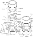
- FIG. 1 shows a steel pipe pile 1 having a cylindrical outer peripheral surface shape that is driven into the ground using a hydraulic hammer, a press-fitting machine, a rotary press-fitting machine, etc. as an example of a steel pipe, and a pair of steel pipe piles 1
- Fig. 2 shows a joint mechanism for connecting with each other in the longitudinal direction.
- the steel pipe pile 1 (1A, 1B) is configured by welding a substantially cylindrical inner joint 10 concentrically to both ends of the pipe body 2 (2A, 2B).
- the inner joint 10 has an inner fitting portion 12 having an outer diameter smaller than that of the base portion 11 extending from a base portion 11 having an outer diameter slightly larger than the outer diameter of the tube body 2.
- the outer diameter of the base 11 is about 18 mm larger than the outer diameter of the tube body 2.
- a single outward circumferential groove 13 for engaging an annular key member 30 described later is formed in an annular shape.
- An engagement recess 14 for engaging an engagement projection 24 provided at an end of the outer joint 20 described later is formed in an annular shape on the end surface of the base 11 facing the inner fitting portion 12.
- subscript A is added to each structure by the side of the inner joint 10 located below when driving the steel pipe pile 1 in the ground.
- a subscript B is added to each component on the inner joint 10 side located on the upper side. That is, one of the pair of inner joints 10A and 10B is the first inner joint, and the other is the second inner joint.
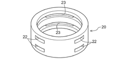
- the outer joint 20 is a cylindrical body made of cast steel having an outer diameter slightly larger than the outer diameter of the tube body 2 and an inner diameter that allows the inner joint 10 to be inserted. It consists of eight unit members 21 formed by dividing into eight equal parts in the circumferential direction. In the present embodiment, the outer diameter of the outer joint 20 is about 18 mm larger than the outer diameter of the tube body 2.
- the unit member 21 can reduce a manufacturing cost compared with the case where it manufactures one by one, for example, by bending an iron plate by using the simple manufacturing method of dividing
- an annular space formed by the outward circumferential groove 13 and the inward circumferential groove 23 becomes a key groove for fitting the key member 30.
- Each unit member 21 is formed with engaging convex portions 24 (24A, 24B) at the upper and lower end portions in the drawing.
- the engagement convex portion 24 (24 A, 24 B) engages with the engagement concave portion 14 (14 A, 14 B) of the inner joint 10, so that the unit member 21 is removed. Is prevented from falling off.
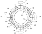
- the four unit members 21 include the key member 30 from the outward circumferential groove 13 and the inward circumferential groove 23 in a state where the outer joint 20 is provided around the inner joint 10.
- a part of the outward circumferential groove 13 (13A, 13B) in the longitudinal direction is exposed outward over the entire width of the outward circumferential groove 13 (13A, 13B).
- Two openings 22 (22A, 22B) are provided. These unit members 21 are opening unit members 21A.
- the opening 22 (22A, 22B) is configured in a shape cut out over the entire width of the inward circumferential groove 23 (23A, 23B) along the location where each inward circumferential groove 23 (23A, 23B) is formed. Yes.
- the key member 30 is inserted from the outer peripheral surface of the outer joint 20 into a key groove constituted by the outward circumferential groove 13 and the inward circumferential groove 23.
- the other four unit members 21 have the same configuration as the opening unit member 21A except that the opening unit 22 (22A, 22B) is not provided. These unit members 21 are standard unit members 21B.
- four open unit members 21A and four standard unit members 21B are arranged alternately around the inner joint 10 to constitute a cylindrical outer joint 20. Since the opening unit member 21A has the opening 22, the rigidity is lower than that of the standard unit member 21B. Therefore, the rigidity of the outer joint 20 as a whole can be homogenized by alternately arranging the opening unit members 21A and the standard unit members 21B.
- the key member 30 is a member disposed in the key groove, and has a plurality of arcuate shapes obtained by dividing an annular body into 16 equal parts in the circumferential direction. It consists of members. However, of the 16 arc-shaped members, 12 are divided key members 31 that are arranged in the key groove and function as the key member 30, and the remaining four have a function as the key member 30 and have openings. 22 is a closing member 32 having a function of closing 22. Twelve divided key members 31 and four closing members 32 are arranged per one key groove, and constitute an annular key member 30 as a whole.
- the dimension in the direction along the longitudinal direction of the steel pipe pile 1 is set to be slightly smaller than the dimension in the direction of the opening 22, and the dimension in the direction along the circumferential direction of the steel pipe pile 1 is The dimension in the direction along the radial direction of the steel pipe pile 1 is set slightly smaller than the dimension in the direction, and the dimension in the direction of the key groove, that is, the outward circumferential groove 13 and the inward circumferential groove 23 is set slightly smaller. Yes.
- the size of the closing member 32 in the direction along the longitudinal direction of the steel pipe pile 1 is set slightly smaller than the size in the direction of the opening 22, and the dimension in the direction along the circumferential direction of the steel pipe pile 1 is that of the opening 22.
- the dimension in the direction along the radial direction of the steel pipe pile 1 is set to be substantially the same as the dimension from the bottom surface of the outward circumferential groove 13 to the surface of the opening 22.
- the closing member 32 is configured to be fixed to the inner joint 10 using the bolt 33 after being inserted into the opening 22.
- the closing member 32 may be configured to be fixed to the outer joint 20.
- a rotation inhibiting key for inhibiting relative movement in the circumferential direction of the inner joint 10A and the inner joint 10B connected via the outer joint 20 is arranged at the boundary between the outer peripheral surfaces of the inner joint 10 and the outer joint 20. It is installed.
- the rotation suppression key includes a counterbore formed on the outer peripheral surface of the base 11 of the inner joint 10 and a counterbore formed on the outer peripheral surface of the outer joint 20 so as to face the counterbore. And straddle the rotation inhibition keyway.
- the dimension and number of the said rotation suppression key and the said spot facing part are suitably set according to the construction method of the steel pipe pile 1.
- the rotation suppression key may be formed integrally with one of the inner joint 10 or the outer joint 20, and in this case, a counterbore is formed only on the other.
- the configuration for suppressing the relative movement of the inner joint 10A and the inner joint 10B in the circumferential direction is not limited to that using the rotation suppression key.
- the length in the longitudinal direction of the steel pipe pile 1 of the engagement convex portion 24 of at least one unit member of the eight unit members 21 and the engagement concave portion 14 with which the engagement convex portion 24 engages is set. Further, it may be configured to be different from the engaging convex portion 24 of the other unit member 21. In this case, the unit member 21 performs the same function as the rotation suppression key.
- the present invention is based on the case where the subsequent steel pipe pile 1B is connected to the steel pipe pile 1A previously driven. A connection method will be described.
- each engagement convex part 24A (14A (14) of the inner joint 10A provided in the upper end of one steel pipe pile 1A driven in advance is set to each engagement convex part 24A (14A).
- the four opening unit members 21A and the four standard unit members 21B are alternately arranged side by side.
- the cylindrical outer joint 20 is provided around the inner joint 10A.
- the other steel pipe pile 1B is suspended from the steel pipe pile 1A, and the engaging convex portion 24B of the opening unit member 21A and the standard unit member 21B constituting the outer joint 20
- the inner joints 10A, 10B of the pair of steel pipe piles 1A, 1B are arranged at predetermined positions inside the outer joint 20.
- the split key member 31 is inserted into the opening 22 of the opening unit member 21A.
- the split key member 31 inserted into the opening 22 is slid along the longitudinal direction of the key groove. Then, the next split key member 31 is inserted into the opening 22.
- the closing member 32 inserted into the opening 22 is fixed using a bolt 33 to close the opening 22.
- the pair of steel pipe piles 1 ⁇ / b> A and 1 ⁇ / b> B can be connected so as not to move relative to the longitudinal direction of the steel pipe pile 1.
- the rotation suppression key includes a counterbore portion formed on the outer peripheral surface of the base portion 11 of the inner joint 10 and a counterbore portion formed on the outer peripheral surface of the outer joint 20 so as to face the counterbore portion.
- a pair of steel pipe piles 1 ⁇ / b> A and 1 ⁇ / b> B are coupled so as not to move relative to each other in the circumferential direction of the steel pipe pile 1 by straddling the configured rotation suppression keyway.
- the unit member 21 constituting the outer joint 20 is formed by dividing a cylindrical body made of cast steel into eight equal parts in the circumferential direction.
- the unit member 21 has a height in a direction along the longitudinal direction of the steel pipe pile 1 in a state where the inner joint 10A and the inner joint 10B are brought into contact with each other, straddling the inner joint 10A and the inner joint 10B. It may be formed from a cylindrical body having a reference distance, a cylindrical body having a distance slightly longer than the reference distance by, for example, about 0.5 mm, or a cylindrical body having a distance longer by about 1.0 mm.
- the unit member 21 formed from a cylindrical body having the reference distance is a reference unit member 21C
- the unit member 21 formed from a cylindrical body having a distance longer than the reference distance is an extended unit member 21D.
- the reference unit member 21C and the extension unit member 21D are also the opening unit member 21A if the opening 22 is provided, and are the standard unit member 21B if the opening 22 is not provided.
- connection unit member 21D At the upper and lower ends of the extension unit member 21D, as with the reference unit member 21C, when the unit member 21 is provided around the inner joint 10, it is engaged with the engagement recesses 14A and 14B of the inner joint 10. Joint convex parts 24A and 24B are formed. Similar to the reference unit member 21C, two annular inward circumferential grooves 23 (23A, 23B) are formed on the inner periphery of the extension unit member 21D.
- the distance between the pair of inward circumferential grooves 23 (23A, 23B) of the reference unit member 21C is between the pair of outward circumferential grooves 13 (13A, 13B) when the inner joint 10A and the inner joint 10B are in contact with each other. Is set to the same distance as The distance between the pair of inward circumferential grooves 23 (23A, 23B) of the extension unit member 21D is between the pair of outward circumferential grooves 13 (13A, 13B) when the inner joint 10A and the inner joint 10B are separated from each other. The same distance is set.
- the distance between the inward circumferential grooves 23 (23A, 23B) of the extension unit member 21D is formed to be wider than the reference distance by 0.5 mm or 1.0 mm. That is, the extension unit member 21D is configured such that the distance between the inward circumferential grooves 23 (23A, 23B) is longer than the distance between the inward circumferential grooves 23 (23A, 23B) of the reference unit member 21C.
- the said 0.5 mm and 1.0 mm are illustrations, and an appropriate value is actually set based on the diameter and dimensional tolerance of the steel pipe pile 1.
- the outer joint 20 is comprised from the reference
- the outer joint 20 is constituted by the extension unit member 21D having a distance 0.5 mm longer than the reference distance, the distance between the opposing surfaces of the inner joint 10A of the steel pipe pile 1A and the inner joint 10B of the steel pipe pile 1B is 0.
- the outer joint 20 is formed by the extension unit member 21D having a distance of 1.0 mm longer than the reference distance with a gap of 5 mm, the opposing surface between the inner joint 10A of the steel pipe pile 1A and the inner joint 10B of the steel pipe pile 1B is formed. A gap of 1.0 mm is generated between them.
- the posture of the steel pipe pile 1 ⁇ / b> A driven in advance is in the vertical direction.
- the reference unit member 21C and the extension unit member 21D are combined, for example, the reference unit member 21C is arranged on the left side in the figure.
- positioning extension unit member 21D on the right side in a figure the attitude
- the steel pipe piles 1A and 1B can be connected while being corrected so as to have a posture close to a vertical posture.
- the inward circumferential groove 23 (23A, 23B) is configured to have a width with a slight margin with respect to the split key member 31, the key of the split key member 31 can be obtained even when the steel pipe piles 1A, 1B are tilted. Slides along the length of the groove are not disturbed.
- the opening 22 of the outer joint 20 is provided at the center of the opening unit member 21A.
- the opening 22 is formed in two adjacent unit members 21 as shown in FIG. It may be formed straddling.
- by shifting the formation position of the opening 22 to the left and right it is possible to suppress a decrease in the rigidity of the opening unit member 21 ⁇ / b> A compared to the case where the opening 22 is formed side by side.
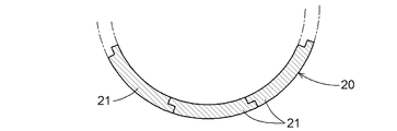
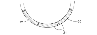
- the division surface of the unit member 21 constituting the outer joint 20 is configured as a plane, but as shown in FIGS. 16 and 17, the opposing surfaces of the adjacent unit members 21 are engaged with each other. You may provide an engaging part. In addition to engaging the engaging convex portion 24 with the engaging concave portion 14, the unit members 21 are prevented from falling off when the adjacent unit members 21 are engaged with each other.
- the outer joint 20 is configured by the unit member 21 divided into eight equal parts, but the outer joint 20 is configured as a cylindrical body made of cast steel as shown in FIG. Also good.
- the inner joint 10 does not have to include the engagement recess 14.
- a mechanism and work for holding the outer joint 20 around the inner joint 10 are required until the split key member 31 is inserted into the key groove. .
- At least the inner joint 10 ⁇ / b> A of the steel pipe pile 1 ⁇ / b> A may be provided with an engagement step portion 15 for holding the outer joint 20 around the inner joint 10.
- the outer peripheral surface of the outer joint 20 may not be formed so as to be flush with the outer peripheral surface of the base 11 of the inner joint 10.
- the inner joint 10 and the outer joint 20 have been described with respect to configurations obtained by processing a cylindrical body made of cast steel into a predetermined shape.
- the inner joint and the outer joint 20 may be formed from a straight seam steel pipe.
- the pipe body 2 can be formed from a spiral steel pipe, for example.
- the straight seam steel pipe is manufactured using a plate winding method in which a flat steel plate is formed into a cylindrical shape using a huge roll or press, and the joint 3 is welded from the inner and outer surfaces.
- the plate winding method is less expensive than methods such as ring forging that produce seamless steel pipes.
- straight seam steel pipes have joints 3 along the longitudinal direction thereof, and are not homogeneous in the circumferential direction like seamless steel pipes, so the same rigidity cannot be obtained in the circumferential direction, and they are vulnerable to internal pressure and torsion.
- the opening unit member 21A and the standard unit member 21B constituting the outer joint 20 the opening unit member 21A in which the opening 22 is formed has a small amount of material in the opening 22, and thus the opening of the opening unit member 21A. Rigidity becomes low compared with the part in which the part 22 is not formed and the standard unit member 21B. Therefore, the joint portion 3 is provided on the standard unit member 21B.
- the outer joint 20 has a standard unit member 21B having a circumferential portion in which the opening 22 is formed and the joint portion 3 in the opening unit member 21A, and the inner joint 10A with respect to the inner joint 10A and the inner joint 10B.
- the inner joint 10 ⁇ / b> B is provided around the inner joint 10 ⁇ / b> B so that it is not at the position where the joint portion 3 is disposed.
- the inner joint 10 ⁇ / b> A and the inner joint 10 ⁇ / b> B are connected so that the respective joint portions 3 do not overlap along the longitudinal direction of the steel pipe pile 1.
- the steel pipe joint mechanism according to the present invention may be used to connect steel pipes such as earth retaining steel pipe sheet piles, landslide deterrent piles, and pier columns in addition to foundation piles for structure installation.
Landscapes
- Engineering & Computer Science (AREA)
- Structural Engineering (AREA)
- Life Sciences & Earth Sciences (AREA)
- General Life Sciences & Earth Sciences (AREA)
- Mining & Mineral Resources (AREA)
- Paleontology (AREA)
- Civil Engineering (AREA)
- General Engineering & Computer Science (AREA)
- Piles And Underground Anchors (AREA)
Abstract
Description
前記ストレートシーム鋼管が有する接合部は、前記外側継手のうち前記開口部とは重ならない位置に配設されていることを特徴とする点にある。
しかし、ストレートシーム鋼管はその長手方向に沿って接合部を有し、シームレス鋼管のように周方向に均質ではないため、周方向において同一の剛性が得られず、内圧やねじれに弱い。
また、外側継手のうち開口部が形成されている周方向部分は、その箇所において材料が少ないため、その他の周方向部分にくらべて剛性が低い。
そこで、開口部は、ストレートシーム鋼管が有する接合部を跨ぐ位置ではない位置となるように外側継手に設けられる。
開口部が形成されている周方向部分と接合部とが、ストレートシーム鋼管の長手方向に沿って重ならないようにすることによって、外側継手において一部がその他の部分よりも剛性が低くなりすぎることを防止できる。
前記ストレートシーム鋼管が有する接合部は、前記内側継手における前記閉鎖部材を固定する位置とは重ならない位置に配設されている点にある。
しかし、ストレートシーム鋼管はその長手方向に沿って接合部を有し、シームレス鋼管のように周方向に均質ではないため、周方向において同一の剛性が得られず、内圧やねじれに弱い。
また、内側継手における前記閉鎖部材を固定する位置には、固定機構としての例えばボルトを固定するためのボルト穴が形成されておりその位置の周方向部分は、その箇所において材料が少ないため、その他の周方向部分にくらべて剛性が低い。
そこで、内側継手における前記閉鎖部材を固定する位置は、ストレートシーム鋼管が有する接合部を跨ぐ位置ではない位置となるように内側継手に設けられる。
内側継手における前記閉鎖部材を固定する位置と接合部とが、ストレートシーム鋼管の長手方向に沿って重ならないようにすることによって、内側継手において一部がその他の部分よりも剛性が低くなりすぎることを防止できる。
前記ストレートシーム鋼管が有する接合部は、回転抑止キー溝を構成する前記内側継手に形成された座ぐり部及び前記外側継手に形成された座ぐり部とは重ならない位置に配設されている点にある。
しかし、ストレートシーム鋼管はその長手方向に沿って接合部を有し、シームレス鋼管のように周方向に均質ではないため、周方向において同一の剛性が得られず、内圧やねじれに弱い。
また、回転抑止キー溝を構成する前記内側継手に形成された座ぐり部及び前記外側継手に形成された座ぐり部が形成されている周方向部分は、その箇所において材料が少ないため、その他の周方向部分にくらべて剛性が低い。
そこで、回転抑止キー溝を構成する前記内側継手に形成された座ぐり部及び前記外側継手に形成された座ぐり部は、ストレートシーム鋼管が有する接合部を跨ぐ位置ではない位置となるように内側継手及び外側継手に設けられる。
回転抑止キー溝を構成する前記内側継手に形成された座ぐり部及び前記外側継手に形成された座ぐり部が形成されている周方向部分と接合部とが、ストレートシーム鋼管の長手方向に沿って重ならないようにすることによって、内側継手及び外側継手において一部がその他の部分よりも剛性が低くなりすぎることを防止できる。
図1は、鋼管の一例としての、油圧ハンマー、圧入機、回転圧入機などを用いて地中に打ち込まれる外周面形状が円筒状の鋼管杭1と、一対の鋼管杭1を鋼管杭1の長手方向に互いに連結するための継手機構とを示している。なお、すべての鋼管杭1は同一の構成であるが、一対の鋼管杭1のうち、一方の鋼管杭1と他方の鋼管杭1を区別して説明する必要があるところについては、一方の鋼管杭1側の各構成の符号に添え字Aを付し、他方の鋼管杭1側の各構成の符号に添え字Bを付している。
内嵌部12の外周には、後述する円環状のキー部材30を係合するための一条の外向き周溝13を円環状に形成してある。基部11の内嵌部12に臨む端面には、後述する外側継手20の端部に備えられた係合凸部24を係合させるための係合凹部14を円環状に形成してある。
ただし、16個の円弧状の部材のうち、12個はキー溝に配置されてキー部材30として機能する分割キー部材31であり、あとの4個はキー部材30としての機能を有するとともに開口部22を閉鎖する機能を有する閉鎖部材32である。
一条のキー溝あたりに、12個の分割キー部材31と4個の閉鎖部材32とが配置され、全体として円環状のキー部材30を構成する。
まず、図1及び図3に示すように、先行して打ち込まれている一方の鋼管杭1Aの上端に設けられた内側継手10Aの係合凹部14A(14)にそれぞれの係合凸部24A(24)を係合させながら、4個の開口単位部材21Aと4個の標準単位部材21Bを交互に並設し、図4に示すように、内側継手10Aの周囲に円筒状の外側継手20を構成する。
この単位部材21は、鋼管杭1の長手方向に沿った方向の高さが、内側継手10Aと内側継手10Bとを当接させた状態において、内側継手10Aと内側継手10Bとに跨って周設される基準距離を有する円筒状体や、前記基準距離より僅かに、例えば0.5mm程度長い距離を有する円筒状体や、1.0mm程度長い距離を有する円筒状体から形成してもよい。なお、前記基準距離を有する円筒状体から形成される単位部材21が基準単位部材21Cであり、前記基準距離より長い距離を有する円筒状体から形成される単位部材21が延長単位部材21Dである。なお、基準単位部材21Cや延長単位部材21Dは、開口部22が備えられていれば開口単位部材21Aでもあり、開口部22が備えられていなければ標準単位部材21Bでもある。
延長単位部材21Dの一対の内向き周溝23(23A,23B)間の距離は、内側継手10Aと内側継手10Bとが離間したときの、一対の外向き周溝13(13A,13B)間と同じ距離に設定されている。
延長単位部材21Dの内向き周溝23(23A,23B)間の距離は、前記基準距離より0.5mmや1.0mmだけ広くなるように形成する。
すなわち、延長単位部材21Dは、内向き周溝23(23A,23B)間の距離が、基準単位部材21Cの内向き周溝23(23A,23B)間の距離より長く構成されている。なお、前記0.5mm及び1.0mmは例示であり、実際には鋼管杭1の直径や、寸法公差に基づいて適当な値が設定される。
一方、前記基準距離より0.5mm長い距離をもった延長単位部材21Dで外側継手20を構成すると、鋼管杭1Aの内側継手10Aと鋼管杭1Bの内側継手10Bとの対向面の間に0.5mmの間隙が生じ、前記基準距離より1.0mm長い距離をもった延長単位部材21Dで外側継手20を構成すると、鋼管杭1Aの内側継手10Aと鋼管杭1Bの内側継手10Bとの対向面の間に1.0mmの間隙が生じることとなる。
また、外側継手20を構成する開口単位部材21A及び標準単位部材21Bのうち、開口部22が形成されている開口単位部材21Aは、開口部22において材料が少ないため、開口単位部材21Aのうち開口部22が形成されていない部分や、標準単位部材21Bにくらべて剛性が低くなってしまう。
そこで、接合部3は、標準単位部材21Bに設けられる。
開口部22が形成されている周方向部分と接合部3とが、ストレートシーム鋼管の長手方向に沿って重ならないようにすることによって、外側継手20において一部がその他の部分よりも剛性が低くなりすぎることを防止できる。
外側継手20のうちの剛性が低い周方向部分と、内側継手10A及び内側継手10Bのうちの剛性が低い周方向部分とが、ストレートシーム鋼管の長手方向に沿って重ならないようにすることによって、継手機構において一部がその他の部分よりも剛性が低くなりすぎることを防止できる。
2 管体
10 内側継手
11 基部
12 内嵌部
13 外向き周溝
14 係合凹部
20 外側継手
21 単位部材
21A 開口単位部材
21B 標準単位部材
21C 基準単位部材
21D 延長単位部材
22 開口部
23 内向き周溝
24 係合凸部
30 キー部材
31 分割キー部材
32 閉鎖部材
33 ボルト
Claims (11)
- 鋼管の継手機構であって、
前記鋼管の一端に設けられた第一内側継手と、他端に設けられた第二内側継手と、
一対の前記鋼管を連結するために、一方の前記鋼管の前記第一内側継手と他方の前記鋼管の前記第二内側継手とを隣接させた状態において、前記第一内側継手と前記第二内側継手とに跨って周設される外側継手と、
前記第一内側継手と前記外側継手、及び、前記第二内側継手と前記外側継手と係合して前記一対の鋼管どうしが該鋼管の長手方向に相対移動することを防止するキー部材とを備え、
前記第一内側継手及び前記第二内側継手のそれぞれの外周には外向き周溝が備えられ、
前記外側継手の内周には、前記第一内側継手及び前記第二内側継手のそれぞれの外周に備えられた前記外向き周溝と対向する内向き周溝が備えられ、
前記外側継手には、前記外側継手の外周面から、前記外向き周溝と前記内向き周溝とから構成されるキー溝に前記キー部材を挿通するための開口部が備えられている
ことを特徴とする継手機構。 - 前記キー部材は、円環の一部を構成する複数の分割キー部材と、前記分割キー部材の機能を有するとともに前記開口部を閉鎖する機能を有する閉鎖部材とを備えていることを特徴とする請求項1に記載の継手機構。
- 前記外側継手は、前記第一内側継手及び前記第二内側継手の周囲に並設される複数の単位部材から構成されていることを特徴とする請求項2に記載の継手機構。
- 前記複数の単位部材は、前記開口部が備えられている開口単位部材と、前記開口部が備えられていない標準単位部材とを含んでいることを特徴とする請求項3に記載の継手機構。
- 前記複数の単位部材は、
前記第一内側継手と前記第二内側継手とを当接させた状態において、前記第一内側継手と前記第二内側継手とに跨って周設される基準単位部材と、
前記第一内側継手と前記第二内側継手とを離間させた状態において、前記第一内側継手と前記第二内側継手とに跨って周設される延長単位部材とを含んでいることを特徴とする請求項3又は4に記載の継手機構。 - 前記第一内側継手及び前記第二内側継手は、それぞれ、基部と前記基部に延設された内嵌部を備え、
前記基部の前記内嵌部に臨む端面には係合凹部が円環状に備えられ、
前記内嵌部の外周に前記外向き周溝が円環状に備えられ、
前記基準単位部材及び前記延長単位部材の上下端部には、前記基準単位部材及び前記延長単位部材を前記第一内側継手及び前記第二内側継手とに跨って周設したときに前記係合凹部に係合可能な一対の係合凸部が備えられ、
前記基準単位部材及び前記延長単位部材の内周に一対の前記外向き周溝に対向する一対の前記内向き周溝が備えられ、
前記基準単位部材の一対の前記内向き周溝間の距離は、前記第一内側継手と前記第二内側継手とが当接したときの、前記一対の外向き周溝間の距離と同じ距離に設定され、
前記延長単位部材の一対の前記内向き周溝間の距離は、前記第一内側継手と前記第二内
側継手とが離間したときの、前記一対の外向き周溝間と同じ距離に設定されていることを特徴とする請求項5に記載の継手機構。 - 少なくとも前記外側継手はストレートシーム鋼管から形成され、
前記ストレートシーム鋼管が有する接合部は、前記外側継手のうち前記開口部とは重ならない位置に配設されていることを特徴とする請求項1から6のいずれか一項に記載の継手機構。 - 少なくとも前記外側継手はストレートシーム鋼管から形成され、
前記ストレートシーム鋼管が有する接合部は、前記内側継手における前記閉鎖部材を固定する位置とは重ならない位置に配設されていることを特徴とする請求項1から6のいずれか一項に記載の継手機構。 - 少なくとも前記外側継手はストレートシーム鋼管から形成され、
前記ストレートシーム鋼管が有する接合部は、回転抑止キー溝を構成する前記内側継手に形成された座ぐり部及び前記外側継手に形成された座ぐり部とは重ならない位置に配設されていることを特徴とする請求項1から6のいずれか一項に記載の継手機構。 - 請求項1から9のいずれか一項に記載の継手機構を用いて一対の鋼管を連結する連結方法であって、
一方の鋼管の一端に設けられた第一内側継手に外側継手を周設するステップと、
前記第一内側継手と他方の鋼管の他端に設けられた第二内側継手とを隣接させて、前記外側継手の内面に前記第二内側継手を挿入し、前記外側継手を前記第一内側継手と前記第二内側継手とに跨らせるステップと、
前記外側継手に備えられた開口部を介して、前記第一内側継手と前記外側継手、及び、前記第二内側継手と前記外側継手と係合して前記一対の鋼管どうしが該鋼管の長手方向に相対移動することを防止するキー部材を、前記外側継手の外周面から、前記第一内側継手及び前記第二内側継手のそれぞれの外周に備えられた外向き周溝と、前記外向き周溝と対向するように前記外側継手の内周に備えられた内向き周溝とから構成されるキー溝に挿通し、前記キー溝に挿通した前記キー部材を、前記キー溝内で周方向にスライドさせ、前記キー溝のうち前記開口部に対応する箇所を除いて、前記キー溝内の所定位置に前記キー部材を配置するステップと、
前記キー部材の機能を有するとともに前記開口部を閉鎖する機能を有する閉鎖部材を用いて前記開口部を閉鎖するステップと、を備えていることを特徴とする連結方法。 - 請求項5から9のいずれか一項に記載の継手機構を用いて一対の鋼管を連結する連結方法であって、
一方の鋼管の一端に設けられた第一内側継手に外側継手を周設するステップと、
前記第一内側継手と他方の鋼管の他端に設けられた第二内側継手とを隣接させて、前記外側継手の内面に前記第二内側継手を挿入し、前記外側継手を前記第一内側継手と前記第二内側継手とに跨らせるステップと、
前記外側継手に備えられた開口部を介して、前記第一内側継手と前記外側継手、及び、前記第二内側継手と前記外側継手と係合して前記一対の鋼管どうしが該鋼管の長手方向に相対移動することを防止するキー部材を、前記外側継手の外周面から、前記第一内側継手及び前記第二内側継手のそれぞれの外周に備えられた外向き周溝と、前記外向き周溝と対向するように前記外側継手の内周に備えられた内向き周溝とから構成されるキー溝に挿通し、前記キー溝に挿通した前記キー部材を、前記キー溝内において周方向にスライドさせ、前記キー溝のうち前記開口部に対応する箇所を除いて、前記キー溝内の所定位置に前記キー部材を配置するステップと、
前記キー部材の機能を有するとともに前記開口部を閉鎖する機能を有する閉鎖部材を用いて前記開口部を閉鎖するステップと、を備え、
前記外側継手を周設するステップにおいて、
前記第一内側継手と前記第二内側継手とに跨って周設される前記外側継手を、前記外側継手を構成する複数の単位部材のうち、一部の単位部材を前記基準単位部材から構成し、他部の単位部材を前記延長単位部材から構成することによって、前記一方の鋼管の軸心と、前記他方の鋼管の軸心とを傾けるステップを備えていることを特徴とする連結方法。
Priority Applications (3)
| Application Number | Priority Date | Filing Date | Title |
|---|---|---|---|
| KR1020167028612A KR20170120486A (ko) | 2015-02-20 | 2015-12-22 | 강관의 이음 기구 및 연결 방법 |
| SG11201608074SA SG11201608074SA (en) | 2015-02-20 | 2015-12-22 | Joint mechanism and connection method for steel pipe |
| US15/302,151 US20170183837A1 (en) | 2015-02-20 | 2015-12-22 | Joint mechanism and connection method for steel pipe |
Applications Claiming Priority (2)
| Application Number | Priority Date | Filing Date | Title |
|---|---|---|---|
| JP2015-032279 | 2015-02-20 | ||
| JP2015032279A JP6456181B2 (ja) | 2015-02-20 | 2015-02-20 | 鋼管の継手機構及び連結方法 |
Publications (1)
| Publication Number | Publication Date |
|---|---|
| WO2016132650A1 true WO2016132650A1 (ja) | 2016-08-25 |
Family
ID=56692620
Family Applications (1)
| Application Number | Title | Priority Date | Filing Date |
|---|---|---|---|
| PCT/JP2015/085892 Ceased WO2016132650A1 (ja) | 2015-02-20 | 2015-12-22 | 鋼管の継手機構及び連結方法 |
Country Status (5)
| Country | Link |
|---|---|
| US (1) | US20170183837A1 (ja) |
| JP (1) | JP6456181B2 (ja) |
| KR (1) | KR20170120486A (ja) |
| SG (1) | SG11201608074SA (ja) |
| WO (1) | WO2016132650A1 (ja) |
Cited By (1)
| Publication number | Priority date | Publication date | Assignee | Title |
|---|---|---|---|---|
| JP2021059838A (ja) * | 2019-10-02 | 2021-04-15 | 旭化成建材株式会社 | 螺旋状羽根付鋼管杭、ソイルセメント合成杭及びその造成方法 |
Families Citing this family (14)
| Publication number | Priority date | Publication date | Assignee | Title |
|---|---|---|---|---|
| JP6749187B2 (ja) * | 2016-09-15 | 2020-09-02 | 株式会社クボタ | 鋼管連結機構及び鋼管連結方法 |
| JP6739300B2 (ja) * | 2016-09-15 | 2020-08-12 | 株式会社クボタ | 鋼管連結機構 |
| US10640987B2 (en) * | 2017-01-13 | 2020-05-05 | Fry Reglet Corporation | Column cover reveal |
| KR102081651B1 (ko) * | 2017-12-26 | 2020-02-27 | 주식회사 포스코 | 강관 연결장치 |
| KR101994467B1 (ko) * | 2018-02-01 | 2019-06-28 | 주식회사 클라썸테크 | 콘크리트 구조물의 연결장치 |
| WO2020166607A1 (ja) * | 2019-02-12 | 2020-08-20 | 株式会社技研製作所 | 杭体継手、杭体連結構造及び杭体連結方法 |
| CN110835910B (zh) * | 2019-10-09 | 2021-07-27 | 福建宝丰管桩有限公司 | 一种预制桩及快捷制作方法 |
| CN110952537B (zh) * | 2019-12-17 | 2021-07-09 | 中电建路桥集团有限公司 | 一种抱箍式连接的phc管桩及其卡箍尺寸确定方法 |
| RU2741881C1 (ru) * | 2020-08-07 | 2021-01-29 | Общество с ограниченной ответственностью «БТ СВАП» | Сборная трубная конструкция |
| RU2741880C1 (ru) * | 2020-08-07 | 2021-01-29 | Общество с ограниченной ответственностью «БТ СВАП» | Соединение свайных и опорных конструкций |
| USD998764S1 (en) * | 2021-12-15 | 2023-09-12 | Kubota Corporation | Load transfer key |
| USD988481S1 (en) * | 2021-12-15 | 2023-06-06 | Kubota Corporation | Mechanical joint |
| JP7496559B2 (ja) * | 2022-07-11 | 2024-06-07 | 株式会社ユニテック | 鋼管部材の連結構造および鋼管部材の連結方法 |
| EP4707733A1 (en) | 2023-06-08 | 2026-03-11 | JFE Steel Corporation | Shape measurement method, shape measurement device, mechanical joint measurement method, mechanical joint measurement system, measurement terminal, mechanical joint manufacturing method, and mechanical joint quality management method |
Citations (6)
| Publication number | Priority date | Publication date | Assignee | Title |
|---|---|---|---|---|
| JP2000328557A (ja) * | 1999-05-19 | 2000-11-28 | Asahi Kasei Kenzai Kk | 杭の継手構造及びその施工方法 |
| JP2005002598A (ja) * | 2003-06-10 | 2005-01-06 | Asahi Kasei Construction Materials Co Ltd | 既製杭の継構造 |
| JP2006291543A (ja) * | 2005-04-08 | 2006-10-26 | Sumitomo Metal Ind Ltd | 鋼管の継手構造 |
| JP2008231732A (ja) * | 2007-03-19 | 2008-10-02 | Maeda Seikan Kk | 杭の継ぎ手構造 |
| JP2012067599A (ja) * | 2012-01-10 | 2012-04-05 | Kubota Corp | 基礎杭の接続工法と基礎杭セットとキー部材 |
| JP2014205952A (ja) * | 2013-04-10 | 2014-10-30 | 新日鐵住金株式会社 | 杭の継手構造 |
-
2015
- 2015-02-20 JP JP2015032279A patent/JP6456181B2/ja active Active
- 2015-12-22 WO PCT/JP2015/085892 patent/WO2016132650A1/ja not_active Ceased
- 2015-12-22 KR KR1020167028612A patent/KR20170120486A/ko not_active Ceased
- 2015-12-22 US US15/302,151 patent/US20170183837A1/en not_active Abandoned
- 2015-12-22 SG SG11201608074SA patent/SG11201608074SA/en unknown
Patent Citations (6)
| Publication number | Priority date | Publication date | Assignee | Title |
|---|---|---|---|---|
| JP2000328557A (ja) * | 1999-05-19 | 2000-11-28 | Asahi Kasei Kenzai Kk | 杭の継手構造及びその施工方法 |
| JP2005002598A (ja) * | 2003-06-10 | 2005-01-06 | Asahi Kasei Construction Materials Co Ltd | 既製杭の継構造 |
| JP2006291543A (ja) * | 2005-04-08 | 2006-10-26 | Sumitomo Metal Ind Ltd | 鋼管の継手構造 |
| JP2008231732A (ja) * | 2007-03-19 | 2008-10-02 | Maeda Seikan Kk | 杭の継ぎ手構造 |
| JP2012067599A (ja) * | 2012-01-10 | 2012-04-05 | Kubota Corp | 基礎杭の接続工法と基礎杭セットとキー部材 |
| JP2014205952A (ja) * | 2013-04-10 | 2014-10-30 | 新日鐵住金株式会社 | 杭の継手構造 |
Cited By (1)
| Publication number | Priority date | Publication date | Assignee | Title |
|---|---|---|---|---|
| JP2021059838A (ja) * | 2019-10-02 | 2021-04-15 | 旭化成建材株式会社 | 螺旋状羽根付鋼管杭、ソイルセメント合成杭及びその造成方法 |
Also Published As
| Publication number | Publication date |
|---|---|
| JP6456181B2 (ja) | 2019-01-23 |
| US20170183837A1 (en) | 2017-06-29 |
| SG11201608074SA (en) | 2016-11-29 |
| JP2016153579A (ja) | 2016-08-25 |
| KR20170120486A (ko) | 2017-10-31 |
Similar Documents
| Publication | Publication Date | Title |
|---|---|---|
| JP6456181B2 (ja) | 鋼管の継手機構及び連結方法 | |
| JP6579945B2 (ja) | 鋼管杭 | |
| JP6594193B2 (ja) | 鋼管の継手機構及び連結方法 | |
| JP4906629B2 (ja) | 柱状体セットとその使用方法 | |
| JP7104641B2 (ja) | 合成セグメント、リング体及び埋設構造物 | |
| JP5772658B2 (ja) | ハット型鋼矢板およびハット型鋼矢板を用いた構造体 | |
| JP6740738B2 (ja) | 鋼製部材の接合方法及び接合構造 | |
| JP4276715B2 (ja) | 管の継手構造 | |
| TWI589753B (zh) | No welded joints pile | |
| JP7543164B2 (ja) | 土留構造物 | |
| JP2011247056A (ja) | 回転圧入杭の接続部材 | |
| JP2022078398A (ja) | 波付き鋼板及び壁構造 | |
| JP5559123B2 (ja) | 梁受け回転ピース | |
| JP4947650B2 (ja) | Pcウェル構造物の構築方法 | |
| JP7653798B2 (ja) | 波付け鋼板及び該波付け鋼板を用いた土留構造物 | |
| JP4413167B2 (ja) | 鉄骨鉄筋コンクリート構造材の補強構造及びその施工方法 | |
| JP2008231732A (ja) | 杭の継ぎ手構造 | |
| WO2016132648A1 (ja) | 鋼管の継手機構及び連結方法 | |
| JP4278105B2 (ja) | 鉄骨鉄筋コンクリート構造材の補強構造及びその施工方法並びに鉄骨補強用部材 | |
| KR102081651B1 (ko) | 강관 연결장치 | |
| JP7222143B1 (ja) | 管路の耐震構造 | |
| JP6497116B2 (ja) | 鋼管杭の回転抑止構造 | |
| JP7543162B2 (ja) | 鋼製土留パネル、該鋼製土留パネルを用いた土留構造物、及び該土留構造物の構築工法 | |
| JP6410595B2 (ja) | 連結部材、連結部材ユニット及び連結方法 | |
| JP7543163B2 (ja) | 鋼製土留パネル及び該鋼製土留パネルを用いた土留構造物 |
Legal Events
| Date | Code | Title | Description |
|---|---|---|---|
| 121 | Ep: the epo has been informed by wipo that ep was designated in this application |
Ref document number: 15882751 Country of ref document: EP Kind code of ref document: A1 |
|
| WWE | Wipo information: entry into national phase |
Ref document number: 15302151 Country of ref document: US |
|
| ENP | Entry into the national phase |
Ref document number: 20167028612 Country of ref document: KR Kind code of ref document: A |
|
| NENP | Non-entry into the national phase |
Ref country code: DE |
|
| 122 | Ep: pct application non-entry in european phase |
Ref document number: 15882751 Country of ref document: EP Kind code of ref document: A1 |