WO2016129347A1 - 端子接続構造、モータ、アクチュエータ、電動パワーステアリング装置および車両 - Google Patents
端子接続構造、モータ、アクチュエータ、電動パワーステアリング装置および車両 Download PDFInfo
- Publication number
- WO2016129347A1 WO2016129347A1 PCT/JP2016/051588 JP2016051588W WO2016129347A1 WO 2016129347 A1 WO2016129347 A1 WO 2016129347A1 JP 2016051588 W JP2016051588 W JP 2016051588W WO 2016129347 A1 WO2016129347 A1 WO 2016129347A1
- Authority
- WO
- WIPO (PCT)
- Prior art keywords
- terminal
- guide hole
- connection structure
- sandwiching
- base
- Prior art date
- Legal status (The legal status is an assumption and is not a legal conclusion. Google has not performed a legal analysis and makes no representation as to the accuracy of the status listed.)
- Ceased
Links
Images


Classifications
-
- H—ELECTRICITY
- H01—ELECTRIC ELEMENTS
- H01R—ELECTRICALLY-CONDUCTIVE CONNECTIONS; STRUCTURAL ASSOCIATIONS OF A PLURALITY OF MUTUALLY-INSULATED ELECTRICAL CONNECTING ELEMENTS; COUPLING DEVICES; CURRENT COLLECTORS
- H01R13/00—Details of coupling devices of the kinds covered by groups H01R12/70 or H01R24/00 - H01R33/00
- H01R13/02—Contact members
- H01R13/10—Sockets for co-operation with pins or blades
- H01R13/11—Resilient sockets
- H01R13/112—Resilient sockets forked sockets having two legs
-
- H—ELECTRICITY
- H01—ELECTRIC ELEMENTS
- H01R—ELECTRICALLY-CONDUCTIVE CONNECTIONS; STRUCTURAL ASSOCIATIONS OF A PLURALITY OF MUTUALLY-INSULATED ELECTRICAL CONNECTING ELEMENTS; COUPLING DEVICES; CURRENT COLLECTORS
- H01R39/00—Rotary current collectors, distributors or interrupters
- H01R39/02—Details for dynamo electric machines
-
- B—PERFORMING OPERATIONS; TRANSPORTING
- B62—LAND VEHICLES FOR TRAVELLING OTHERWISE THAN ON RAILS
- B62D—MOTOR VEHICLES; TRAILERS
- B62D5/00—Power-assisted or power-driven steering
- B62D5/04—Power-assisted or power-driven steering electrical, e.g. using an electric servo-motor connected to, or forming part of, the steering gear
-
- H—ELECTRICITY
- H01—ELECTRIC ELEMENTS
- H01R—ELECTRICALLY-CONDUCTIVE CONNECTIONS; STRUCTURAL ASSOCIATIONS OF A PLURALITY OF MUTUALLY-INSULATED ELECTRICAL CONNECTING ELEMENTS; COUPLING DEVICES; CURRENT COLLECTORS
- H01R43/00—Apparatus or processes specially adapted for manufacturing, assembling, maintaining, or repairing of line connectors or current collectors or for joining electric conductors
- H01R43/26—Apparatus or processes specially adapted for manufacturing, assembling, maintaining, or repairing of line connectors or current collectors or for joining electric conductors for engaging or disengaging the two parts of a coupling device
-
- H—ELECTRICITY
- H01—ELECTRIC ELEMENTS
- H01R—ELECTRICALLY-CONDUCTIVE CONNECTIONS; STRUCTURAL ASSOCIATIONS OF A PLURALITY OF MUTUALLY-INSULATED ELECTRICAL CONNECTING ELEMENTS; COUPLING DEVICES; CURRENT COLLECTORS
- H01R9/00—Structural associations of a plurality of mutually-insulated electrical connecting elements, e.g. terminal strips or terminal blocks; Terminals or binding posts mounted upon a base or in a case; Bases therefor
- H01R9/22—Bases, e.g. strip, block, panel
- H01R9/24—Terminal blocks
-
- H—ELECTRICITY
- H02—GENERATION; CONVERSION OR DISTRIBUTION OF ELECTRIC POWER
- H02K—DYNAMO-ELECTRIC MACHINES
- H02K11/00—Structural association of dynamo-electric machines with electric components or with devices for shielding, monitoring or protection
- H02K11/30—Structural association with control circuits or drive circuits
- H02K11/33—Drive circuits, e.g. power electronics
-
- H—ELECTRICITY
- H02—GENERATION; CONVERSION OR DISTRIBUTION OF ELECTRIC POWER
- H02K—DYNAMO-ELECTRIC MACHINES
- H02K5/00—Casings; Enclosures; Supports
- H02K5/04—Casings or enclosures characterised by the shape, form or construction thereof
- H02K5/22—Auxiliary parts of casings not covered by groups H02K5/06-H02K5/20, e.g. shaped to form connection boxes or terminal boxes
- H02K5/225—Terminal boxes or connection arrangements
-
- H—ELECTRICITY
- H01—ELECTRIC ELEMENTS
- H01R—ELECTRICALLY-CONDUCTIVE CONNECTIONS; STRUCTURAL ASSOCIATIONS OF A PLURALITY OF MUTUALLY-INSULATED ELECTRICAL CONNECTING ELEMENTS; COUPLING DEVICES; CURRENT COLLECTORS
- H01R13/00—Details of coupling devices of the kinds covered by groups H01R12/70 or H01R24/00 - H01R33/00
- H01R13/62—Means for facilitating engagement or disengagement of coupling parts or for holding them in engagement
- H01R13/627—Snap or like fastening
- H01R13/6271—Latching means integral with the housing
- H01R13/6273—Latching means integral with the housing comprising two latching arms
-
- H—ELECTRICITY
- H01—ELECTRIC ELEMENTS
- H01R—ELECTRICALLY-CONDUCTIVE CONNECTIONS; STRUCTURAL ASSOCIATIONS OF A PLURALITY OF MUTUALLY-INSULATED ELECTRICAL CONNECTING ELEMENTS; COUPLING DEVICES; CURRENT COLLECTORS
- H01R2105/00—Three poles
Definitions
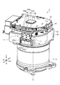
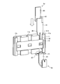
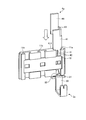
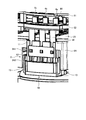
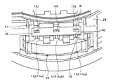
- FIG. 14 is a view in which the first terminal is exposed by omitting the motor-side casing in FIG. 13.
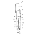
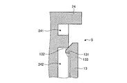
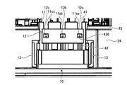
- FIG. 15 is a cross-sectional view showing the temporary fixing mechanism when the second terminal reaches one end of the guide hole.
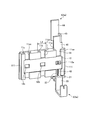
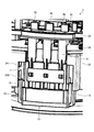
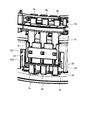
- FIG. 16 is an enlarged view in which the periphery of the first terminal in FIG. 13 is enlarged.
- FIG. 17 is a perspective view showing the periphery of the terminal connection structure when the first terminal and the second terminal are connected.
- FIG. 18 is a cross-sectional view showing the temporary fixing mechanism when the first terminal and the second terminal are connected.
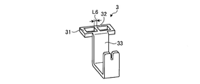
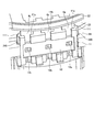
- FIG. 19 is an enlarged side view showing the periphery of the terminal connection structure according to this embodiment.
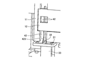
- FIG. 20 is an enlarged perspective view showing the periphery of the terminal connection structure according to this embodiment.
- FIG. 21 is a schematic diagram showing a vehicle according to the present embodiment.
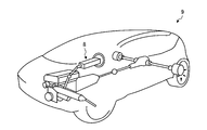
- FIG. 1 is a schematic diagram showing an electric power steering apparatus according to the present embodiment.
- the electric power steering device 8 is mounted on the vehicle 9 as shown in FIG. 21, for example.
- the electric power steering device 8 includes a steering wheel 81, a steering shaft 82, an actuator 83, a universal joint 84, a lower shaft 85, and a universal joint 86 in the order in which the force applied from the steering wheel (driver) is transmitted.
- the steering torque (including auxiliary steering torque) output via the output shaft 82 b is transmitted to the lower shaft 85 via the universal joint 84 and further transmitted to the pinion shaft 87 via the universal joint 86.
- the steering torque transmitted to the pinion shaft 87 is transmitted to the tie rod 89 via the steering gear 88 and changes the direction of the wheels.
Landscapes
- Engineering & Computer Science (AREA)
- Power Engineering (AREA)
- Microelectronics & Electronic Packaging (AREA)
- Manufacturing & Machinery (AREA)
- Chemical & Material Sciences (AREA)
- Combustion & Propulsion (AREA)
- Transportation (AREA)
- Mechanical Engineering (AREA)
- Power Steering Mechanism (AREA)
- Motor Or Generator Frames (AREA)
- Details Of Connecting Devices For Male And Female Coupling (AREA)
Priority Applications (3)
| Application Number | Priority Date | Filing Date | Title |
|---|---|---|---|
| EP16748992.1A EP3223375B1 (en) | 2015-02-10 | 2016-01-20 | Terminal connection structure, motor, actuator, electric power steering device, and vehicle |
| US15/540,778 US9929525B2 (en) | 2015-02-10 | 2016-01-20 | Terminal connection structure for electricpower steering system of a vehicle |
| CN201680005414.0A CN107112692B (zh) | 2015-02-10 | 2016-01-20 | 端子连接机构、电动机、致动器、电动动力转向装置及车辆 |
Applications Claiming Priority (2)
| Application Number | Priority Date | Filing Date | Title |
|---|---|---|---|
| JP2015024607A JP6107847B2 (ja) | 2015-02-10 | 2015-02-10 | 端子接続構造、モータ、アクチュエータ、電動パワーステアリング装置および車両 |
| JP2015-024607 | 2015-02-10 |
Publications (1)
| Publication Number | Publication Date |
|---|---|
| WO2016129347A1 true WO2016129347A1 (ja) | 2016-08-18 |
Family
ID=56615435
Family Applications (1)
| Application Number | Title | Priority Date | Filing Date |
|---|---|---|---|
| PCT/JP2016/051588 Ceased WO2016129347A1 (ja) | 2015-02-10 | 2016-01-20 | 端子接続構造、モータ、アクチュエータ、電動パワーステアリング装置および車両 |
Country Status (5)
| Country | Link |
|---|---|
| US (1) | US9929525B2 (enExample) |
| EP (1) | EP3223375B1 (enExample) |
| JP (1) | JP6107847B2 (enExample) |
| CN (1) | CN107112692B (enExample) |
| WO (1) | WO2016129347A1 (enExample) |
Families Citing this family (11)
| Publication number | Priority date | Publication date | Assignee | Title |
|---|---|---|---|---|
| JP6433420B2 (ja) * | 2015-12-25 | 2018-12-05 | 本田技研工業株式会社 | トルクセンサの端子台構造 |
| WO2018038161A1 (ja) * | 2016-08-23 | 2018-03-01 | 日本精工株式会社 | 端子接続部品及びこれを用いた制御装置とモータとの端子接続構造 |
| KR101892895B1 (ko) | 2018-03-07 | 2018-10-04 | (주)에이테크오토모티브 | Epb 액츄에이터 기어박스의 단자구조 |
| JP1626561S (ja) * | 2018-04-26 | 2019-03-18 | パワーステアリング用制御器付きモータ | |
| DE102018216484B4 (de) | 2018-09-26 | 2022-02-17 | Robert Bosch Gmbh | Lenkvorrichtung mit einer Steckverbindereinheit zur elektrischen Kontaktierung einer Lenksensoreinheit |
| JP7403308B2 (ja) * | 2019-12-16 | 2023-12-22 | ミネベアミツミ株式会社 | モータ |
| JP7267214B2 (ja) * | 2020-01-21 | 2023-05-01 | ヒロセ電機株式会社 | ケーブル用コネクタ |
| KR102540340B1 (ko) | 2021-04-23 | 2023-06-08 | 계양전기 주식회사 | 전동액츄에이터의 단자 결합구조 |
| CN117581458A (zh) * | 2021-06-15 | 2024-02-20 | 日立安斯泰莫株式会社 | 电动机装置及其制造方法、端子连接机构和方法以及电动制动装置 |
| WO2024245934A1 (de) * | 2023-05-29 | 2024-12-05 | Brose Fahrzeugteile SE & Co. Kommanditgesellschaft, Würzburg | Vorrichtung für einen elektromotor |
| KR102839501B1 (ko) * | 2023-07-18 | 2025-07-28 | 캄텍주식회사 | 전기 접속 구조를 구비하는 오일 펌프 |
Citations (4)
| Publication number | Priority date | Publication date | Assignee | Title |
|---|---|---|---|---|
| JPS59115692U (ja) * | 1983-01-21 | 1984-08-04 | 富士通電装株式会社 | 接栓接続の案内構造 |
| JPH06510884A (ja) * | 1991-09-23 | 1994-12-01 | ミネソタ マイニング アンド マニュファクチャリング カンパニー | 遠距離通信システム用改良交差接続システム |
| JP2010508646A (ja) * | 2006-11-06 | 2010-03-18 | ローベルト ボツシユ ゲゼルシヤフト ミツト ベシユレンクテル ハフツング | 圧接接続部並びに2つの構成部分を接続するための方法 |
| JP2013196973A (ja) * | 2012-03-21 | 2013-09-30 | Hitachi Automotive Systems Ltd | 端子接続部および電動アクチュエータ |
Family Cites Families (10)
| Publication number | Priority date | Publication date | Assignee | Title |
|---|---|---|---|---|
| AR208483A1 (es) * | 1975-11-10 | 1976-12-27 | Amp Inc | Terminal electrico |
| US5281163A (en) * | 1991-09-23 | 1994-01-25 | Minnesota Mining And Manufacturing Company | Cross connect system for telecommunications systems |
| US6045392A (en) * | 1998-06-30 | 2000-04-04 | Lucent Technologies Inc. | Modified index strip with integrated push cap for wire termination |
| US6716054B1 (en) * | 2002-12-16 | 2004-04-06 | Tyco Electronics Corporation | Plug and block connector system for differential contact pairs |
| US7223115B2 (en) * | 2005-06-03 | 2007-05-29 | Commscope, Inc. Of North Carolina | Cross-connect systems with connector blocks having balanced insulation displacement contacts |
| US7273398B2 (en) * | 2005-11-01 | 2007-09-25 | Tyco Electronics Corporation | Electrical device carrier contact assembly |
| DE102007026094B4 (de) * | 2007-06-05 | 2023-05-11 | Tyco Electronics Services Gmbh | Kontaktelement für einen Steckverbinder für Leiterplatten |
| JP5634610B2 (ja) * | 2011-09-12 | 2014-12-03 | 三菱電機株式会社 | 電動式駆動装置 |
| JP5827157B2 (ja) * | 2012-03-21 | 2015-12-02 | 日立オートモティブシステムズ株式会社 | 電動アクチュエータの端子接続構造 |
| US9444311B2 (en) | 2012-08-28 | 2016-09-13 | Mitsubishi Electric Corporation | Electric driving device and method for manufacturing electric driving device |
-
2015
- 2015-02-10 JP JP2015024607A patent/JP6107847B2/ja not_active Expired - Fee Related
-
2016
- 2016-01-20 EP EP16748992.1A patent/EP3223375B1/en active Active
- 2016-01-20 WO PCT/JP2016/051588 patent/WO2016129347A1/ja not_active Ceased
- 2016-01-20 US US15/540,778 patent/US9929525B2/en not_active Expired - Fee Related
- 2016-01-20 CN CN201680005414.0A patent/CN107112692B/zh not_active Expired - Fee Related
Patent Citations (4)
| Publication number | Priority date | Publication date | Assignee | Title |
|---|---|---|---|---|
| JPS59115692U (ja) * | 1983-01-21 | 1984-08-04 | 富士通電装株式会社 | 接栓接続の案内構造 |
| JPH06510884A (ja) * | 1991-09-23 | 1994-12-01 | ミネソタ マイニング アンド マニュファクチャリング カンパニー | 遠距離通信システム用改良交差接続システム |
| JP2010508646A (ja) * | 2006-11-06 | 2010-03-18 | ローベルト ボツシユ ゲゼルシヤフト ミツト ベシユレンクテル ハフツング | 圧接接続部並びに2つの構成部分を接続するための方法 |
| JP2013196973A (ja) * | 2012-03-21 | 2013-09-30 | Hitachi Automotive Systems Ltd | 端子接続部および電動アクチュエータ |
Also Published As
| Publication number | Publication date |
|---|---|
| EP3223375B1 (en) | 2019-03-13 |
| US20170373451A1 (en) | 2017-12-28 |
| JP2016149216A (ja) | 2016-08-18 |
| JP6107847B2 (ja) | 2017-04-05 |
| EP3223375A1 (en) | 2017-09-27 |
| CN107112692A (zh) | 2017-08-29 |
| CN107112692B (zh) | 2018-09-11 |
| US9929525B2 (en) | 2018-03-27 |
| EP3223375A4 (en) | 2018-02-21 |
Similar Documents
| Publication | Publication Date | Title |
|---|---|---|
| JP6107847B2 (ja) | 端子接続構造、モータ、アクチュエータ、電動パワーステアリング装置および車両 | |
| JP6652211B2 (ja) | 端子接続部品及びこれを用いた制御装置とモータとの端子接続構造 | |
| JP6038383B2 (ja) | モータ駆動装置 | |
| CN108093665B (zh) | 无刷电动机及搭载无刷电动机的电动助力转向装置和车辆 | |
| WO2007007880A1 (ja) | 電動パワーステアリング装置 | |
| CN105720748B (zh) | 驱动装置 | |
| EP3168967B1 (en) | Connecting part for electric motor and electic motor control device, connecting structure for electric motor and electric motor control device using this connecting part, and electric power steering device, electric actuator, and vehicle using this connecting structure | |
| JP2008079465A (ja) | ブラシレスモータ | |
| WO2019235024A1 (ja) | 通電端子組立体及び電動駆動装置 | |
| JP2017171071A (ja) | 電動パワーステアリング装置の製造方法及びトルク検出センサの調整方法 | |
| JP2012201294A (ja) | 電動パワーステアリング装置及びその組立方法 | |
| JP5304710B2 (ja) | 電動パワーステアリング装置及びその組立方法 | |
| JP7041546B2 (ja) | 電子制御装置、及び電動駆動装置 | |
| JP6048631B1 (ja) | トルク検出装置、電動パワーステアリング装置及び車両 | |
| JP6197924B2 (ja) | 電動モータとその制御装置との接続部品及びこれを用いた電動モータとその制御装置との接続構造、並びに、これを用いた電動パワーステアリング装置、電動アクチュエータ、及び、車両 | |
| JP5299344B2 (ja) | 電動パワーステアリング装置 | |
| WO2025158947A1 (ja) | 駆動装置 | |
| JP2015082891A (ja) | ブラシレスモータ及び電動パワーステアリング装置 |
Legal Events
| Date | Code | Title | Description |
|---|---|---|---|
| 121 | Ep: the epo has been informed by wipo that ep was designated in this application |
Ref document number: 16748992 Country of ref document: EP Kind code of ref document: A1 |
|
| REEP | Request for entry into the european phase |
Ref document number: 2016748992 Country of ref document: EP |
|
| WWE | Wipo information: entry into national phase |
Ref document number: 15540778 Country of ref document: US |
|
| NENP | Non-entry into the national phase |
Ref country code: DE |