WO2016129310A1 - 車輪用軸受装置 - Google Patents
車輪用軸受装置 Download PDFInfo
- Publication number
- WO2016129310A1 WO2016129310A1 PCT/JP2016/050618 JP2016050618W WO2016129310A1 WO 2016129310 A1 WO2016129310 A1 WO 2016129310A1 JP 2016050618 W JP2016050618 W JP 2016050618W WO 2016129310 A1 WO2016129310 A1 WO 2016129310A1
- Authority
- WO
- WIPO (PCT)
- Prior art keywords
- wheel bearing
- sensor
- wheel
- magnetic encoder
- joint member
- Prior art date
- Legal status (The legal status is an assumption and is not a legal conclusion. Google has not performed a legal analysis and makes no representation as to the accuracy of the status listed.)
- Ceased
Links
Images

Classifications
-
- B—PERFORMING OPERATIONS; TRANSPORTING
- B60—VEHICLES IN GENERAL
- B60B—VEHICLE WHEELS; CASTORS; AXLES FOR WHEELS OR CASTORS; INCREASING WHEEL ADHESION
- B60B35/00—Axle units; Parts thereof ; Arrangements for lubrication of axles
- B60B35/12—Torque-transmitting axles
- B60B35/18—Arrangement of bearings
-
- B—PERFORMING OPERATIONS; TRANSPORTING
- B60—VEHICLES IN GENERAL
- B60B—VEHICLE WHEELS; CASTORS; AXLES FOR WHEELS OR CASTORS; INCREASING WHEEL ADHESION
- B60B27/00—Hubs
- B60B27/0015—Hubs for driven wheels
- B60B27/0036—Hubs for driven wheels comprising homokinetic joints
- B60B27/0042—Hubs for driven wheels comprising homokinetic joints characterised by the fixation of the homokinetic joint to the hub
-
- B—PERFORMING OPERATIONS; TRANSPORTING
- B60—VEHICLES IN GENERAL
- B60B—VEHICLE WHEELS; CASTORS; AXLES FOR WHEELS OR CASTORS; INCREASING WHEEL ADHESION
- B60B27/00—Hubs
- B60B27/0047—Hubs characterised by functional integration of other elements
- B60B27/0068—Hubs characterised by functional integration of other elements the element being a sensor
-
- F—MECHANICAL ENGINEERING; LIGHTING; HEATING; WEAPONS; BLASTING
- F16—ENGINEERING ELEMENTS AND UNITS; GENERAL MEASURES FOR PRODUCING AND MAINTAINING EFFECTIVE FUNCTIONING OF MACHINES OR INSTALLATIONS; THERMAL INSULATION IN GENERAL
- F16C—SHAFTS; FLEXIBLE SHAFTS; ELEMENTS OR CRANKSHAFT MECHANISMS; ROTARY BODIES OTHER THAN GEARING ELEMENTS; BEARINGS
- F16C33/00—Parts of bearings; Special methods for making bearings or parts thereof
- F16C33/72—Sealings
- F16C33/76—Sealings of ball or roller bearings
- F16C33/768—Sealings of ball or roller bearings between relatively stationary parts, i.e. static seals
-
- F—MECHANICAL ENGINEERING; LIGHTING; HEATING; WEAPONS; BLASTING
- F16—ENGINEERING ELEMENTS AND UNITS; GENERAL MEASURES FOR PRODUCING AND MAINTAINING EFFECTIVE FUNCTIONING OF MACHINES OR INSTALLATIONS; THERMAL INSULATION IN GENERAL
- F16C—SHAFTS; FLEXIBLE SHAFTS; ELEMENTS OR CRANKSHAFT MECHANISMS; ROTARY BODIES OTHER THAN GEARING ELEMENTS; BEARINGS
- F16C35/00—Rigid support of bearing units; Housings, e.g. caps, covers
- F16C35/04—Rigid support of bearing units; Housings, e.g. caps, covers in the case of ball or roller bearings
- F16C35/06—Mounting or dismounting of ball or roller bearings; Fixing them onto shaft or in housing
- F16C35/063—Fixing them on the shaft
-
- F—MECHANICAL ENGINEERING; LIGHTING; HEATING; WEAPONS; BLASTING
- F16—ENGINEERING ELEMENTS AND UNITS; GENERAL MEASURES FOR PRODUCING AND MAINTAINING EFFECTIVE FUNCTIONING OF MACHINES OR INSTALLATIONS; THERMAL INSULATION IN GENERAL
- F16C—SHAFTS; FLEXIBLE SHAFTS; ELEMENTS OR CRANKSHAFT MECHANISMS; ROTARY BODIES OTHER THAN GEARING ELEMENTS; BEARINGS
- F16C41/00—Other accessories, e.g. devices integrated in the bearing not relating to the bearing function as such
- F16C41/007—Encoders, e.g. parts with a plurality of alternating magnetic poles
-
- F—MECHANICAL ENGINEERING; LIGHTING; HEATING; WEAPONS; BLASTING
- F16—ENGINEERING ELEMENTS AND UNITS; GENERAL MEASURES FOR PRODUCING AND MAINTAINING EFFECTIVE FUNCTIONING OF MACHINES OR INSTALLATIONS; THERMAL INSULATION IN GENERAL
- F16D—COUPLINGS FOR TRANSMITTING ROTATION; CLUTCHES; BRAKES
- F16D1/00—Couplings for rigidly connecting two coaxial shafts or other movable machine elements
- F16D1/06—Couplings for rigidly connecting two coaxial shafts or other movable machine elements for attachment of a member on a shaft or on a shaft-end
- F16D1/076—Couplings for rigidly connecting two coaxial shafts or other movable machine elements for attachment of a member on a shaft or on a shaft-end by clamping together two faces perpendicular to the axis of rotation, e.g. with bolted flanges
-
- F—MECHANICAL ENGINEERING; LIGHTING; HEATING; WEAPONS; BLASTING
- F16—ENGINEERING ELEMENTS AND UNITS; GENERAL MEASURES FOR PRODUCING AND MAINTAINING EFFECTIVE FUNCTIONING OF MACHINES OR INSTALLATIONS; THERMAL INSULATION IN GENERAL
- F16C—SHAFTS; FLEXIBLE SHAFTS; ELEMENTS OR CRANKSHAFT MECHANISMS; ROTARY BODIES OTHER THAN GEARING ELEMENTS; BEARINGS
- F16C19/00—Bearings with rolling contact, for exclusively rotary movement
- F16C19/02—Bearings with rolling contact, for exclusively rotary movement with bearing balls essentially of the same size in one or more circular rows
- F16C19/14—Bearings with rolling contact, for exclusively rotary movement with bearing balls essentially of the same size in one or more circular rows for both radial and axial load
- F16C19/18—Bearings with rolling contact, for exclusively rotary movement with bearing balls essentially of the same size in one or more circular rows for both radial and axial load with two or more rows of balls
- F16C19/181—Bearings with rolling contact, for exclusively rotary movement with bearing balls essentially of the same size in one or more circular rows for both radial and axial load with two or more rows of balls with angular contact
- F16C19/183—Bearings with rolling contact, for exclusively rotary movement with bearing balls essentially of the same size in one or more circular rows for both radial and axial load with two or more rows of balls with angular contact with two rows at opposite angles
- F16C19/184—Bearings with rolling contact, for exclusively rotary movement with bearing balls essentially of the same size in one or more circular rows for both radial and axial load with two or more rows of balls with angular contact with two rows at opposite angles in O-arrangement
- F16C19/186—Bearings with rolling contact, for exclusively rotary movement with bearing balls essentially of the same size in one or more circular rows for both radial and axial load with two or more rows of balls with angular contact with two rows at opposite angles in O-arrangement with three raceways provided integrally on parts other than race rings, e.g. third generation hubs
-
- F—MECHANICAL ENGINEERING; LIGHTING; HEATING; WEAPONS; BLASTING
- F16—ENGINEERING ELEMENTS AND UNITS; GENERAL MEASURES FOR PRODUCING AND MAINTAINING EFFECTIVE FUNCTIONING OF MACHINES OR INSTALLATIONS; THERMAL INSULATION IN GENERAL
- F16C—SHAFTS; FLEXIBLE SHAFTS; ELEMENTS OR CRANKSHAFT MECHANISMS; ROTARY BODIES OTHER THAN GEARING ELEMENTS; BEARINGS
- F16C2326/00—Articles relating to transporting
- F16C2326/01—Parts of vehicles in general
- F16C2326/02—Wheel hubs or castors
-
- F—MECHANICAL ENGINEERING; LIGHTING; HEATING; WEAPONS; BLASTING
- F16—ENGINEERING ELEMENTS AND UNITS; GENERAL MEASURES FOR PRODUCING AND MAINTAINING EFFECTIVE FUNCTIONING OF MACHINES OR INSTALLATIONS; THERMAL INSULATION IN GENERAL
- F16D—COUPLINGS FOR TRANSMITTING ROTATION; CLUTCHES; BRAKES
- F16D1/00—Couplings for rigidly connecting two coaxial shafts or other movable machine elements
- F16D1/10—Quick-acting couplings in which the parts are connected by simply bringing them together axially
- F16D2001/103—Quick-acting couplings in which the parts are connected by simply bringing them together axially the torque is transmitted via splined connections
-
- F—MECHANICAL ENGINEERING; LIGHTING; HEATING; WEAPONS; BLASTING
- F16—ENGINEERING ELEMENTS AND UNITS; GENERAL MEASURES FOR PRODUCING AND MAINTAINING EFFECTIVE FUNCTIONING OF MACHINES OR INSTALLATIONS; THERMAL INSULATION IN GENERAL
- F16D—COUPLINGS FOR TRANSMITTING ROTATION; CLUTCHES; BRAKES
- F16D3/00—Yielding couplings, i.e. with means permitting movement between the connected parts during the drive
- F16D3/16—Universal joints in which flexibility is produced by means of pivots or sliding or rolling connecting parts
- F16D3/20—Universal joints in which flexibility is produced by means of pivots or sliding or rolling connecting parts one coupling part entering a sleeve of the other coupling part and connected thereto by sliding or rolling members
- F16D3/22—Universal joints in which flexibility is produced by means of pivots or sliding or rolling connecting parts one coupling part entering a sleeve of the other coupling part and connected thereto by sliding or rolling members the rolling members being balls, rollers, or the like, guided in grooves or sockets in both coupling parts
- F16D3/223—Universal joints in which flexibility is produced by means of pivots or sliding or rolling connecting parts one coupling part entering a sleeve of the other coupling part and connected thereto by sliding or rolling members the rolling members being balls, rollers, or the like, guided in grooves or sockets in both coupling parts the rolling members being guided in grooves in both coupling parts
- F16D2003/22326—Attachments to the outer joint member, i.e. attachments to the exterior of the outer joint member or to the shaft of the outer joint member
Definitions
- the present invention relates to a wheel bearing device that rotatably supports driving wheels (front wheels of FF vehicles, rear wheels of FR vehicles, all wheels of 4WD vehicles), for example, with respect to an automobile suspension.
- the present applicant has previously proposed a wheel bearing device in which a main part is composed of, for example, a wheel bearing including a hub ring, an inner ring, a double row rolling element and an outer ring, and a fixed type constant velocity universal joint.
- a wheel bearing device in which a main part is composed of, for example, a wheel bearing including a hub ring, an inner ring, a double row rolling element and an outer ring, and a fixed type constant velocity universal joint.
- a wheel bearing device in which a main part is composed of, for example, a wheel bearing including a hub ring, an inner ring, a double row rolling element and an outer ring, and a fixed type constant velocity universal joint.
- the wheel bearing device disclosed in Patent Document 1 has a face spline structure in which a hub wheel of a wheel bearing and an outer joint member of a constant velocity universal joint are coupled so as to be able to transmit torque.
- the wheel bearing device includes a structure in which a hub wheel of a wheel bearing and an outer joint member of a constant velocity universal joint are fastened together by a bolt member.
- the face spline structure in this wheel bearing device has a face spline in which a plurality of radially extending projections are formed along the circumferential direction on the axial end surface of the outer joint member of the constant velocity universal joint. Moreover, it has the face spline which formed the several recessed part extended in radial direction on the axial direction end surface of the hub ring of the wheel bearing along the circumferential direction. The axial end face of the outer joint member and the axial end face of the hub wheel are brought into contact with each other, and the both face splines are engaged to form an uneven fitting structure.
- a vehicle body mounting flange is provided on the outer ring of the wheel bearing.
- the wheel bearing device is assembled to the vehicle body by attaching the vehicle body mounting flange to a knuckle extending from the suspension device of the vehicle body by bolting.
- the wheel bearing device disclosed in Patent Document 1 is assembled to the vehicle body by being attached to a knuckle extending from the suspension device of the vehicle body. Therefore, when the wheel bearing device is assembled to the vehicle body, the knuckle extending from the suspension device of the vehicle body hides the meshing surface between the outer joint member of the constant velocity universal joint and the hub wheel of the wheel bearing. .
- the present invention has been proposed in view of the above-described improvements, and the object of the present invention is to provide a wheel that can easily confirm the coupling state between the wheel bearing and the constant velocity universal joint when assembled to the vehicle body. It is to provide a bearing device for use.
- the wheel bearing device includes an outer member in which a double row outer raceway surface is formed on an inner peripheral surface, and an inner member in which a double row inner raceway surface facing the outer raceway surface is formed on an outer peripheral surface.
- a wheel bearing comprising a member and a double row rolling element interposed between the outer raceway surface of the outer member and the inner raceway surface of the inner member, and the shaft of the inner member of the wheel bearing
- the wheel bearing device includes the wheel bearing and the constant velocity universal joint.
- a magnetic encoder facing a sensor mounted on the outer member side of the wheel bearing is mounted on the outer joint member of the constant velocity universal joint, and the axial direction of the magnetic encoder with respect to the sensor It is characterized in that the size of the separation distance can be detected.
- the axial end face of the inner member and the outer joint member in the concave-convex fitting structure between the wheel bearing and the constant velocity universal joint can be detected by detecting the axial distance of the magnetic encoder relative to the sensor.
- the state of meshing with the end face in the axial direction can be confirmed without depending on visual inspection when assembled to the vehicle body.
- the axial separation distance of the magnetic encoder with respect to the sensor is larger than when the meshing state is complete. Become. By comparing the magnitude relationship of the axial separation distance of the magnetic encoder with respect to this sensor, it is possible to determine whether or not the meshing state between the axial end surface of the inner member and the axial end surface of the outer joint member is good.
- the magnetic encoder according to the present invention is preferably attached to the shoulder portion of the outer joint member facing the inner member of the wheel bearing and disposed in parallel with the axial end surface of the outer joint member.
- the magnetic encoder is arranged in parallel with the axial end face of the outer joint member, it is possible to easily detect the magnitude of the axial distance of the magnetic encoder relative to the sensor. As a result, it is possible to accurately determine whether or not the meshing state between the axial end surface of the inner member and the axial end surface of the outer joint member is good.
- the sensor in the present invention is composed of a rotational speed sensor that measures the rotational speed of the outer joint member of the constant velocity universal joint, and can detect the presence or absence of sensor output based on the magnitude of the axial separation distance of the magnetic encoder with respect to the rotational speed sensor. Is desirable.
- the sensor according to the present invention is preferably composed of a magnetic sensor that measures the magnetic force of the magnetic encoder, and it is desirable to be able to detect the magnitude of the sensor output based on the magnitude of the axial separation distance of the magnetic encoder relative to the magnetic sensor.
- the magnetic force of the magnetic encoder is measured by a magnetic sensor.
- the measured value of the magnetic force output from the magnetic sensor is larger than when the meshing state is incomplete.
- the present invention it is possible to detect the magnitude of the axial separation distance of the magnetic encoder with respect to the sensor, so that in the concave-convex fitting structure between the wheel bearing and the constant velocity universal joint, the axial end surface and the outer side of the inner member Whether the meshing state with the axial end surface of the joint member is good or bad can be determined without depending on visual observation when assembled to the vehicle body. As a result, it is possible to prevent the occurrence of poor assembly of the vehicle body due to the incomplete meshing state, and it is possible to provide a wheel bearing device with high quality and excellent reliability.
- FIG. 7 shows a state before the constant velocity universal joint 7 is assembled to the wheel bearing 6
- FIG. 8 shows a state after the constant velocity universal joint 7 is assembled to the wheel bearing 6.
- the side closer to the outside of the vehicle body is referred to as the outboard side (left side of the drawing) and the side closer to the center is referred to as the inboard side (right side of the drawing) with the wheel bearing device assembled to the vehicle body Called.
- the wheel bearing device shown in FIGS. 7 and 8 has the same speed as the wheel bearing 6 including the hub wheel 1 and the inner ring 2, which are inner members, double-row rolling elements 3 and 4, and the outer ring 5 which is an outer member.
- the main part is composed of the universal joint 7.
- the overall configuration of the wheel bearing device will be described before describing the characteristic configuration of this embodiment.
- the hub wheel 1 is provided with an inner raceway surface 8 on the outboard side on the outer peripheral surface thereof and a wheel mounting flange 10 for mounting a wheel (not shown). Hub bolts for fixing the wheel disc are planted at equal intervals in the circumferential direction of the wheel mounting flange 10.
- An inner ring 2 is fitted to a small diameter step portion 11 formed on the inboard side outer peripheral surface of the hub wheel 1, and an inner raceway surface 9 on the inboard side is formed on the outer peripheral surface of the inner ring 2.
- the inner ring 2 is press-fitted with an appropriate tightening allowance to prevent creep.
- the outboard side inner raceway surface 8 formed on the outer peripheral surface of the hub wheel 1 and the inboard side inner raceway surface 9 formed on the outer peripheral surface of the inner ring 2 constitute a double row raceway surface.
- the inner ring 2 is press-fitted into the small-diameter step portion 11 of the hub wheel 1, and the inboard side end portion of the small-diameter step portion 11 is crimped outward by swing caulking, and the inner ring 2 is prevented from coming off with the caulking portion 12.
- it is integrated with the hub wheel 1 and preload is applied to the wheel bearing 6.
- the outer ring 5 has double-row outer raceways 13 and 14 that are opposed to the inner raceways 8 and 9 of the hub wheel 1 and the inner race 2 on the inner peripheral surface, and a knuckle 45 extending from a suspension device of a vehicle body (not shown).
- a vehicle body mounting flange 54 for mounting to (see FIG. 1) is provided.
- the wheel bearing 6 provided with the hub wheel 1, the inner ring 2 and the outer ring 5 has a double-row angular ball bearing structure, and the inner raceway surfaces 8 and 9 formed on the outer peripheral surfaces of the hub wheel 1 and the inner ring 2 and the outer ring.
- 5, rolling elements 3, 4 are interposed between outer raceway surfaces 13, 14 formed on the inner peripheral surface of 5, and rolling elements 3, 4 in each row are supported at equal intervals in the circumferential direction by cages 15, 16. Has the structure.
- a pair of seals 17, 18 that seal the annular space between the outer ring 5, the hub ring 1, and the inner ring 2 are provided at both end openings of the wheel bearing 6 so as to be in sliding contact with the outer peripheral surfaces of the hub ring 1 and the inner ring 2. 5 is fitted to the inner peripheral surfaces of both end portions to prevent leakage of grease filled inside and entry of water and foreign matters from the outside.
- the constant velocity universal joint 7 is a fixed constant velocity universal joint constituting a part of the drive shaft, and is provided at one end of an intermediate shaft (not shown).
- the constant velocity universal joint 7 includes an outer joint member 20 in which a track groove 19 is formed on the inner peripheral surface, and an inner joint member in which a track groove 21 facing the track groove 19 of the outer joint member 20 is formed on the outer peripheral surface. 22, between the track groove 19 of the outer joint member 20 and the track groove 21 of the inner joint member 22, and between the inner peripheral surface of the outer joint member 20 and the outer peripheral surface of the inner joint member 22. And a cage 24 that holds the ball 23 interposed therebetween.
- the outer joint member 20 accommodates internal parts including the inner joint member 22, the ball 23 and the cage 24, and a female thread portion 26 penetrating in the axial direction is formed at the bottom portion 25.
- the inner joint member 22 is press-fitted with the shaft end of the intermediate shaft, and is coupled to the intermediate shaft so as to transmit torque by spline fitting.
- a resin bellows boot (not shown) is mounted between the outer joint member 20 of the constant velocity universal joint 7 and the intermediate shaft, and the opening of the outer joint member 20 is closed with the boot.
- This boot prevents leakage of a lubricant such as grease sealed inside the joint and prevents foreign matter from entering from the outside of the joint.
- This wheel bearing device has the following uneven fitting structure in which the hub wheel 1 of the wheel bearing 6 and the outer joint member 20 of the constant velocity universal joint 7 are coupled so as to be able to transmit torque.
- a plurality of radially extending convex portions 27 are formed along the circumferential direction on the axial end surface of the hub wheel 1 of the wheel bearing 6, that is, on the axial end surface of the crimped portion 12.
- a face spline 29 is provided.
- a plurality of radially extending recesses 28 are formed along the circumferential direction on the axial end surface of the outer joint member 20 of the constant velocity universal joint 7, that is, on the axial end surface of the bottom portion 25 thereof.
- the face spline 30 is provided.
- This uneven fitting structure is a face spline structure X in which the axial end face of the crimped portion 12 of the hub wheel 1 and the axial end face of the bottom portion 25 of the outer joint member 20 are abutted and the face splines 29 and 30 are engaged with each other. It has become.
- this wheel bearing device has the following tightening structure by the bolt member 31. That is, the bolt member 31 is inserted into the hole 32 of the hub wheel 1, and the male screw portion 33 formed at the tip of the bolt member 31 is screwed into the female screw portion 26 formed in the bottom portion 25 of the outer joint member 20. Then, the head 34 of the bolt member 31 is tightened in a state where the bolt 34 is locked to the bottom surface 36 of the concave portion 35 of the hub wheel 1.
- the constant velocity universal joint 7 is firmly fixed to the hub wheel 1 by tightening the face splines 29 and 30 facing each other at the caulking portion 12 of the hub wheel 1 and the bottom portion 25 of the outer joint member 20 with the bolt member 31.
- the wheel bearing 6 has a structure in which the inner ring 2 is prevented from coming off by the caulking portion 12 and is integrated with the hub wheel 1, so that it can be separated from the constant velocity universal joint 7.
- the wheel bearing device includes a seal structure that seals the face spline structure X between the wheel bearing 6 and the constant velocity universal joint 7.
- this seal structure is integrally joined to the core metal 38 attached to the shoulder portion 37 of the outer joint member 20 and the tip of the core metal 38 by vulcanization adhesion or the like.
- the seal member 40 is composed of a rubber seal lip 39.
- the cored bar 38 is formed by pressing a steel plate having rust prevention ability. As shown in FIG. 11, a base end cylindrical part 41 press-fitted into the shoulder part 37 of the outer joint member 20 and a seal lip 39 are provided. The joined tip cylindrical portion 42 and the intermediate flange portion 43 positioned between the proximal cylindrical portion 41 and the distal cylindrical portion 42 are integrally formed.
- the seal lip 39 of the seal member 40 is brought into elastic contact with the axial end surface of the inner ring 2 of the wheel bearing 6. Thereby, it is possible to prevent foreign matters such as rainwater and dust from entering the meshing portions of the face splines 29 and 30 from outside. Further, it is possible to prevent the grease filled in the meshing portions of both the face splines 29 and 30 from leaking to the outside. As a result, corrosion and wear of both face splines 29 and 30 can be suppressed.
- the seal member 40 shown in FIG. 11 has a structure in which a bifurcated seal lip 39 is joined to the tip of the core metal 38.
- a bifurcated seal lip 39 it is also possible to use a seal member 40 in which a convex seal lip 44 is joined to the tip of a cored bar 38 as shown in FIG.
- the overall configuration of the wheel bearing device in this embodiment is as described above, but the meshing detection structure of both face splines 29 and 30 as a characteristic configuration will be described below.
- the wheel bearing device shown in FIG. 8 couples the wheel bearing 6 and the constant velocity universal joint 7 with the face spline structure X so that torque can be transmitted, and the wheel bearing 6 and the constant velocity universal joint 7 are bolt members. 31 is fastened and integrated. As shown in FIG. 1, this wheel bearing device is assembled to a vehicle body by fastening and fixing a vehicle body mounting flange 54 of the outer ring 5 of the wheel bearing 6 to a knuckle 45 extending from a suspension device of the vehicle body with a bolt 46. .
- this wheel bearing device is equipped with a rotation speed detection device that controls the anti-lock brake system (ABS) and detects the rotation speed of the wheel.
- this rotational speed detection device has a meshing detection structure for both face splines 29 and 30.
- the engagement detection structure of both face splines 29 and 30 in this embodiment is attached to the rotational speed sensor 47 attached to the knuckle 45 located on the outer ring side of the wheel bearing 6 and the outer joint member 20 of the constant velocity universal joint 7.
- the magnetic encoder 48 is opposed to the rotational speed sensor 47.
- Rotational speed sensor 47 includes, for example, a Hall element or a magnetoresistive element (MR element).
- the rotational speed sensor 47 is led out from a through hole 51 provided in the knuckle 45 while being supported by a holder 50 fixed to the knuckle 45 with a screw 49, and is connected to the wheel bearing 6 and the constant velocity universal joint 7. It is arranged in the space between.
- MR element magnetoresistive element
- the rotation speed sensor 47 arranged on the fixed side by the knuckle 45 detects the rotation speed of the outer joint member 20 of the constant velocity universal joint 7 by the magnetic encoder 48 arranged on the rotation side by the seal member 40.
- the magnetic encoder 48 is made of a ring-shaped rubber magnet in which N poles and S poles are alternately formed in the circumferential direction.
- the magnetic encoder 48 is provided on the core metal 38 of the seal member 40 attached to the shoulder portion 37 of the outer joint member 20. That is, it is affixed to the outer peripheral surface of the intermediate flange portion 43 of the core metal 38 and is disposed in parallel with the axial end surface of the bottom portion 25 of the outer joint member 20.
- the rotational speed sensor 47 and the magnetic encoder 48 are disposed to face each other with a gap 52 in the space between the wheel bearing 6 and the constant velocity universal joint 7.
- the axial separation distance of the magnetic encoder 48 with respect to 47 is N.
- the case where the meshing state is incomplete means, for example, a case where the tooth tip of one face spline 29 and the tooth tip of the other face spline 30 are in contact with each other.
- the provision of the magnetic encoder 48 on the outer joint member 20 makes it possible to determine a meshing failure based on the displacement of the outer joint member 20 toward the inboard side. Further, since the magnetic encoder 48 is arranged in parallel with the axial end surface of the outer joint member 20, it is possible to easily detect the magnitude of the axial separation distance of the magnetic encoder 48 with respect to the rotational speed sensor 47. As a result, it is possible to accurately determine whether the mesh state of both the face splines 29 and 30 is good or bad.
- the rotational speed sensor 47 when the rotational speed sensor 47 is employed in the engagement detection structure of both the face splines 29 and 30, when the engagement state of both the face splines 29 and 30 is complete, that is, the axis of the magnetic encoder 48 with respect to the sensor 47.
- the sensitivity of the rotational speed sensor 47 is adjusted in advance so that the output of the rotational speed sensor 47 can be obtained when the direction separation distance is M.
- the rotational speed sensor is compared by comparing the axial distance of the magnetic encoder 48 with respect to the rotational speed sensor 47 between the case where the meshing state of both the face splines 29 and 30 is incomplete and the case where the mesh is incomplete. Based on whether or not the output of 47 is obtained, it is possible to determine whether or not the meshing state of both the face splines 29 and 30 is complete when assembled to the vehicle body.
- ABS rotational speed sensor 47 is used as the sensor for detecting the meshing state of the two face splines 29 and 30 has been described above, but the present invention is not limited to this, As shown in FIG. 5, it is also possible to use a magnetic sensor 53 that measures the magnetic force (magnetic flux density) of the magnetic encoder 48.
- Examples of the magnetic sensor 53 include a hall probe.
- the mounting structure of the magnetic sensor 53, the magnetic encoder 48, and the mounting structure thereof are the same as those of the rotation speed sensor 47 shown in FIG. To do.
- the measured value of the magnetic force (magnetic flux density) of the magnetic encoder 48 is smaller than when the meshing state is perfect.
Landscapes
- Engineering & Computer Science (AREA)
- General Engineering & Computer Science (AREA)
- Mechanical Engineering (AREA)
- Rolling Contact Bearings (AREA)
Abstract
内周面に複列の外側軌道面13,14が形成された外輪5と、外周面に外側軌道面13,14と対向する複列の内側軌道面8,9が形成されたハブ輪1および内輪2と、外輪5の外側軌道面13,14とハブ輪1および内輪2の内側軌道面8,9との間に介装された複列の転動体3,4とからなる車輪用軸受6を備え、その車輪用軸受6のハブ輪1の軸方向端面と等速自在継手7の外側継手部材20の軸方向端面とをフェイススプライン29,30によりトルク伝達可能に結合させた車輪用軸受装置において、車輪用軸受6の外輪側に取り付けられた回転速度センサ47と対峙する磁気エンコーダ48を等速自在継手7の外側継手部材20に取り付け、回転速度センサ47に対する磁気エンコーダ48の軸方向離間距離の大小に基づくセンサ出力の有無を検出可能とする。
Description
本発明は、例えば自動車の懸架装置に対して駆動車輪(FF車の前輪、FR車の後輪、4WD車の全輪)を回転自在に支持する車輪用軸受装置に関する。
本出願人は、例えば、ハブ輪、内輪、複列の転動体および外輪からなる車輪用軸受と、固定式等速自在継手とで主要部が構成された車輪用軸受装置を先に提案している(例えば、特許文献1参照)。
この特許文献1で開示された車輪用軸受装置は、車輪用軸受のハブ輪と等速自在継手の外側継手部材とをトルク伝達可能に結合させたフェイススプライン構造を具備している。また、この車輪用軸受装置は、車輪用軸受のハブ輪と等速自在継手の外側継手部材とをボルト部材で締結することにより一体化した構造を具備する。
この車輪用軸受装置におけるフェイススプライン構造では、等速自在継手の外側継手部材の軸方向端面に、径方向に延びる複数の凸部を周方向に沿って形成したフェイススプラインを有する。また、車輪用軸受のハブ輪の軸方向端面に、径方向に延びる複数の凹部を周方向に沿って形成したフェイススプラインを有する。そして、外側継手部材の軸方向端面とハブ輪の軸方向端面とを突き合わせ、両者のフェイススプラインを噛み合わせることにより凹凸嵌合構造としている。
一方、車輪用軸受の外輪には車体取付フランジが設けられている。この車体取付フランジを、車体の懸架装置から延びるナックルにボルト締め付けで取り付けることにより、車輪用軸受装置が車体に組み付けられている。
ところで、特許文献1で開示された車輪用軸受装置は、前述したように、車体の懸架装置から延びるナックルに取り付けられることにより車体に組み付けられる。そのため、この車輪用軸受装置の車体への組み付け時、車体の懸架装置から延びるナックルによって、等速自在継手の外側継手部材と車輪用軸受のハブ輪との噛み合わせ面が隠れてしまうことになる。
その結果、外側継手部材のフェイススプラインとハブ輪のフェイススプラインとが確実に噛み合った状態にあるか否かを確認することが困難である。万一、両者のフェイススプラインの噛み合いが不完全であると、等速自在継手から車輪用軸受へのトルク伝達を効率よく行うことが困難となる。また、等速自在継手と車輪用軸受とを締結するボルト部材が緩むおそれがある。
そこで、本発明は前述の改善点に鑑みて提案されたもので、その目的とするところは、車体への組み付け時、車輪用軸受と等速自在継手との結合状態を容易に確認し得る車輪用軸受装置を提供することにある。
本発明に係る車輪用軸受装置は、内周面に複列の外側軌道面が形成された外方部材と、外周面に外側軌道面と対向する複列の内側軌道面が形成された内方部材と、外方部材の外側軌道面と内方部材の内側軌道面との間に介装された複列の転動体とからなる車輪用軸受を備え、その車輪用軸受の内方部材の軸方向端面と等速自在継手の外側継手部材の軸方向端面とを凹凸嵌合構造によりトルク伝達可能に結合させた構造を具備する。以上のように、この車輪用軸受装置は、車輪用軸受と等速自在継手とで構成されている。
前述の目的を達成するための技術的手段として、車輪用軸受の外方部材側に取り付けられたセンサと対峙する磁気エンコーダを等速自在継手の外側継手部材に取り付け、センサに対する磁気エンコーダの軸方向離間距離の大小を検出可能としたことを特徴とする。
本発明では、センサに対する磁気エンコーダの軸方向離間距離の大小を検出可能としたことにより、車輪用軸受と等速自在継手との凹凸嵌合構造において、内方部材の軸方向端面と外側継手部材の軸方向端面との噛み合い状態を、車体への組み付け時、目視に依存することなく確認することができる。
つまり、内方部材の軸方向端面と外側継手部材の軸方向端面との噛み合い状態が不完全な場合には、その噛み合い状態が完全な場合よりも、センサに対する磁気エンコーダの軸方向離間距離が大きくなる。このセンサに対する磁気エンコーダの軸方向離間距離の大小関係の比較により、内方部材の軸方向端面と外側継手部材の軸方向端面との噛み合い状態の良不良を判定することができる。
本発明における磁気エンコーダは、車輪用軸受の内方部材と対向する外側継手部材の肩部に取り付けられ、その外側継手部材の軸方向端面と平行に配置されていることが望ましい。
このように、磁気エンコーダを外側継手部材の軸方向端面と平行に配置すれば、センサに対する磁気エンコーダの軸方向離間距離の大小を容易に検出することが可能となる。その結果、内方部材の軸方向端面と外側継手部材の軸方向端面との噛み合い状態の良不良を正確に判定することができる。
本発明におけるセンサは、等速自在継手の外側継手部材の回転速度を計測する回転速度センサで構成され、その回転速度センサに対する磁気エンコーダの軸方向離間距離の大小に基づくセンサ出力の有無を検出可能とすることが望ましい。
この場合、内方部材の軸方向端面と外側継手部材の軸方向端面との噛み合い状態が不完全であると、回転速度センサに対する磁気エンコーダの軸方向離間距離が大きいことから、センサ出力が得られない。一方、内方部材の軸方向端面と外側継手部材の軸方向端面との噛み合い状態が完全であると、回転速度センサに対する磁気エンコーダの軸方向離間距離が小さいことから、センサ出力が得られる。
このようにして、センサ出力が得られるか否かに基づいて、内方部材の軸方向端面と外側継手部材の軸方向端面との噛み合い状態が完全であるか否かを判定することができる。なお、この場合、内方部材の軸方向端面と外側継手部材の軸方向端面との噛み合い状態が完全な場合にセンサ出力が得られるように、センサ感度を設定する必要がある。
本発明におけるセンサは、磁気エンコーダの磁力を計測する磁気センサで構成され、その磁気センサに対する磁気エンコーダの軸方向離間距離の大小に基づくセンサ出力の大小を検出可能とすることが望ましい。
この場合、磁気センサによって磁気エンコーダの磁力を計測する。内方部材の軸方向端面と外側継手部材の軸方向端面との噛み合い状態が完全な場合には、その噛み合い状態が不完全な場合よりも、磁気センサから出力される磁力の計測値が大きくなる。
このようにして、磁気センサから出力される計測値の大小に基づいて、内方部材の軸方向端面と外側継手部材の軸方向端面との噛み合い状態が完全であるか否かを判定することができる。
本発明によれば、センサに対する磁気エンコーダの軸方向離間距離の大小を検出可能としたことにより、車輪用軸受と等速自在継手との凹凸嵌合構造において、内方部材の軸方向端面と外側継手部材の軸方向端面との噛み合い状態の良不良を、車体への組み付け時、目視に依存することなく判定することができる。その結果、不完全な噛み合い状態による車体組み付け不良の発生を未然に防止することができ、高品質で信頼性に優れた車輪用軸受装置を提供することができる。
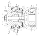
本発明に係る車輪用軸受装置の実施形態を以下に詳述する。図7は車輪用軸受6に等速自在継手7を組み付ける前の状態を示し、図8は車輪用軸受6に等速自在継手7を組み付けた後の状態を示す。なお、以下の説明では、車輪用軸受装置を車体に組み付けた状態で、車体の外側寄りとなる側をアウトボード側(図面左側)と称し、中央寄りとなる側をインボード側(図面右側)と称する。
図7および図8に示す車輪用軸受装置は、内方部材であるハブ輪1および内輪2、複列の転動体3,4、外方部材である外輪5からなる車輪用軸受6と等速自在継手7とで主要部が構成されている。なお、この実施形態の特徴的な構成を説明する前に車輪用軸受装置の全体構成を説明する。
ハブ輪1は、その外周面にアウトボード側の内側軌道面8が形成されると共に、車輪(図示せず)を取り付けるための車輪取付フランジ10を備えている。この車輪取付フランジ10の円周方向等間隔に、ホイールディスクを固定するためのハブボルトが植設されている。このハブ輪1のインボード側外周面に形成された小径段部11に内輪2を嵌合させ、この内輪2の外周面にインボード側の内側軌道面9が形成されている。
内輪2は、クリープを防ぐために適当な締め代をもって圧入されている。ハブ輪1の外周面に形成されたアウトボード側の内側軌道面8と、内輪2の外周面に形成されたインボード側の内側軌道面9とで複列の軌道面を構成する。この内輪2をハブ輪1の小径段部11に圧入し、その小径段部11のインボード側端部を揺動加締めにより外側に加締め、その加締め部12でもって内輪2を抜け止めしてハブ輪1と一体化し、車輪用軸受6に予圧を付与している。
外輪5は、内周面にハブ輪1および内輪2の内側軌道面8,9と対向する複列の外側軌道面13,14が形成され、車体(図示せず)の懸架装置から延びるナックル45(図1参照)に取り付けるための車体取付フランジ54を備えている。
前述したハブ輪1、内輪2および外輪5を備えた車輪用軸受6は、複列のアンギュラ玉軸受構造で、ハブ輪1および内輪2の外周面に形成された内側軌道面8,9と外輪5の内周面に形成された外側軌道面13,14との間に転動体3,4を介在させ、各列の転動体3,4を保持器15,16により円周方向等間隔に支持した構造を有する。
車輪用軸受6の両端開口部には、ハブ輪1と内輪2の外周面に摺接するように、外輪5とハブ輪1および内輪2との環状空間を密封する一対のシール17,18が外輪5の両端部内周面に嵌合され、内部に充填されたグリースの漏洩ならびに外部からの水や異物の侵入を防止するようになっている。
等速自在継手7は、ドライブシャフトの一部を構成する固定式等速自在継手であり、中間シャフト(図示せず)の一端に設けられている。この等速自在継手7は、内周面にトラック溝19が形成された外側継手部材20と、その外側継手部材20のトラック溝19と対向するトラック溝21が外周面に形成された内側継手部材22と、外側継手部材20のトラック溝19と内側継手部材22のトラック溝21との間に組み込まれたボール23と、外側継手部材20の内周面と内側継手部材22の外周面との間に介在してボール23を保持するケージ24とで構成されている。
外側継手部材20は、内側継手部材22、ボール23およびケージ24からなる内部部品を収容し、その底部25には、軸方向に貫通する雌ねじ部26が形成されている。内側継手部材22は、中間シャフトの軸端が圧入されてスプライン嵌合により中間シャフトとトルク伝達可能に結合されている。
等速自在継手7の外側継手部材20と中間シャフトとの間に樹脂製の蛇腹状ブーツ(図示せず)を装着し、外側継手部材20の開口部をブーツで閉塞した構造としている。このブーツにより、継手内部に封入されたグリース等の潤滑剤の漏洩を防ぐと共に、継手外部からの異物侵入を防止するようにしている。
この車輪用軸受装置は、車輪用軸受6のハブ輪1と等速自在継手7の外側継手部材20とをトルク伝達可能に結合させた以下の凹凸嵌合構造を具備する。
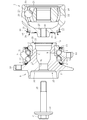
図9に示すように、車輪用軸受6のハブ輪1の軸方向端面、つまり、その加締め部12の軸方向端面に、径方向に延びる複数の凸部27を周方向に沿って形成したフェイススプライン29を有する。また、図10に示すように、等速自在継手7の外側継手部材20の軸方向端面、つまり、その底部25の軸方向端面に、径方向に延びる複数の凹部28を周方向に沿って形成したフェイススプライン30を有する。
この凹凸嵌合構造は、ハブ輪1の加締め部12の軸方向端面と外側継手部材20の底部25の軸方向端面とを突き合わせ、両者のフェイススプライン29,30を噛み合わせたフェイススプライン構造Xとなっている。
また、この車輪用軸受装置は、ボルト部材31による以下の締め付け構造を具備する。つまり、ボルト部材31をハブ輪1の孔32に挿通し、外側継手部材20の底部25に形成された雌ねじ部26に、ボルト部材31の先端に形成された雄ねじ部33を螺合させる。そして、ボルト部材31の頭部34をハブ輪1の凹状部35の底面36に係止させた状態で締め付ける。
このボルト部材31でハブ輪1の加締め部12と外側継手部材20の底部25で対向する両フェイススプライン29,30を締め付けることにより、等速自在継手7をハブ輪1に強固に固定する。なお、車輪用軸受6は、加締め部12でもって内輪2を抜け止めしてハブ輪1と一体化した構造を有することから、等速自在継手7と分離可能になっている。
また、この車輪用軸受装置は、車輪用軸受6と等速自在継手7との間に、フェイススプライン構造Xを密封するシール構造を具備する。
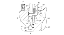
このシール構造は、図7および図8に示すように、外側継手部材20の肩部37に装着された芯金38と、この芯金38の先端に加硫接着などで一体的に接合されたゴム製のシールリップ39とからなるシール部材40で構成されている。
芯金38は、防錆能を有する鋼板をプレス加工により成形したもので、図11に示すように、外側継手部材20の肩部37に圧入された基端円筒部41と、シールリップ39が接合された先端円筒部42と、その基端円筒部41と先端円筒部42との間に位置する中間フランジ部43とが一体的に形成された構成をなす。
このシール構造では、シール部材40のシールリップ39を車輪用軸受6の内輪2の軸方向端面に弾圧接触させる。これにより、外部からの雨水やダスト等の異物が両フェイススプライン29,30の噛み合い部分に侵入するのを防止することができる。また、両フェイススプライン29,30の噛み合い部分に充填されたグリースが外部に漏洩するのを防止することができる。その結果、両フェイススプライン29,30の腐食や摩耗を抑制することができる。
なお、図11に示すシール部材40は、二股状のシールリップ39を芯金38の先端に接合した構造を具備する。このような二股状のシールリップ39以外に、図12に示すように、凸状のシールリップ44を芯金38の先端に接合したシール部材40を使用することも可能である。
この実施形態における車輪用軸受装置の全体構成は、前述のとおりであるが、特徴的な構成としての両フェイススプライン29,30の噛み合い検知構造について、以下に説明する。
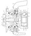
図8に示す車輪用軸受装置は、車輪用軸受6と等速自在継手7とをフェイススプライン構造Xでもってトルク伝達可能に結合すると共に、車輪用軸受6と等速自在継手7とをボルト部材31により締結して一体化している。この車輪用軸受装置は、図1に示すように、車輪用軸受6の外輪5の車体取付フランジ54を、車体の懸架装置から延びるナックル45にボルト46で締め付け固定することにより、車体に組み付けられる。
ここで、この車輪用軸受装置では、アンチロックブレーキシステム(ABS)を制御し、車輪の回転速度を検出する回転速度検出装置を搭載している。この実施形態では、この回転速度検出装置を両フェイススプライン29,30の噛み合い検知構造としている。
この実施形態における両フェイススプライン29,30の噛み合い検知構造は、車輪用軸受6の外輪側に位置するナックル45に取り付けられた回転速度センサ47と、等速自在継手7の外側継手部材20に取り付けられて回転速度センサ47と対峙する磁気エンコーダ48とで構成されている。
回転速度センサ47としては、例えばホール素子や磁気抵抗素子(MR素子)などがある。この回転速度センサ47は、ナックル45にねじ49で固定されたホルダ50に支持された状態で、ナックル45に設けられた貫通孔51から導出され、車輪用軸受6と等速自在継手7との間の空間に配置されている。
ナックル45により固定側に配置された回転速度センサ47は、シール部材40により回転側に配置された磁気エンコーダ48により、等速自在継手7の外側継手部材20の回転速度を検出するものである。
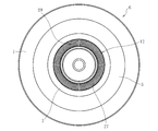
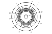
磁気エンコーダ48は、周方向にN極とS極が交互に形成されたリング状のゴム磁石からなる。この磁気エンコーダ48は、外側継手部材20の肩部37に取り付けたシール部材40の芯金38に設けられている。つまり、芯金38の中間フランジ部43の外周面に貼着されて外側継手部材20の底部25の軸方向端面と平行に配置されている。回転速度センサ47と磁気エンコーダ48とは、車輪用軸受6と等速自在継手7との間の空間でギャップ52を介して対向配置されている。
以上の構成からなる両フェイススプライン29,30の噛み合い検知構造では、回転速度センサ47に対する磁気エンコーダ48の軸方向離間距離の大小に基づくセンサ出力の有無を検出可能としている。これにより、ハブ輪1のフェイススプライン29と外側継手部材20のフェイススプライン30との噛み合い状態を、車体への組み付け時、目視に依存することなく確認することができる。
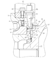
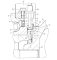
ハブ輪1の加締め部12の軸方向端面と外側継手部材20の底部25の軸方向端面における両フェイススプライン29,30の噛み合い状態が完全な場合(図1参照)には、図2に示すように、回転速度センサ47と磁気エンコーダ48との間のギャップ52において、回転速度センサ47に対する磁気エンコーダ48の軸方向離間距離がMとなる。
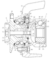
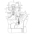
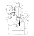
一方、両フェイススプライン29,30の噛み合い状態が不完全な場合(図3参照)には、図4に示すように、回転速度センサ47と磁気エンコーダ48との間のギャップ52において、回転速度センサ47に対する磁気エンコーダ48の軸方向離間距離がNとなる。なお、噛み合い状態が不完全な場合とは、例えば一方のフェイススプライン29の歯先と他方のフェイススプライン30の歯先とが当接している場合を意味する。
このように、両フェイススプライン29,30の噛み合い状態が不完全な場合には、外側継手部材20がインボード側へずれるため、その噛み合い状態が完全な場合よりも、回転速度センサ47に対する磁気エンコーダ48の軸方向離間距離が大きくなる(M<N)。従って、この回転速度センサ47に対する磁気エンコーダ48の軸方向離間距離の大小関係の比較により、両フェイススプライン29,30の噛み合い状態の良不良を判定することができる。
なお、磁気エンコーダ48を外側継手部材20に設けることにより、外側継手部材20のインボード側へのずれに基づいて噛み合い状態の不良を判定することができる。また、磁気エンコーダ48を外側継手部材20の軸方向端面と平行に配置したことにより、回転速度センサ47に対する磁気エンコーダ48の軸方向離間距離の大小を容易に検出することが可能となる。その結果、両フェイススプライン29,30の噛み合い状態の良不良を正確に判定することができる。
以上のように、両フェイススプライン29,30の噛み合い検知構造に、回転速度センサ47を採用した場合、両フェイススプライン29,30の噛み合い状態が完全な時、つまり、センサ47に対する磁気エンコーダ48の軸方向離間距離がMとなっている時に、回転速度センサ47の出力が得られるように、その回転速度センサ47の感度を予め調整しておく。
その結果、両フェイススプライン29,30の噛み合い状態が不完全な場合、センサ47に対する磁気エンコーダ48の軸方向離間距離Nが完全な噛み合い状態の場合よりも大きいことから(N>M)、回転速度センサ47の出力が得られない。
このようにして、両フェイススプライン29,30の噛み合い状態が不完全な場合と完全な場合とで、回転速度センサ47に対する磁気エンコーダ48の軸方向離間距離の大小を比較することにより、回転速度センサ47の出力が得られるか否かに基づいて、車体への組み付け時、両フェイススプライン29,30の噛み合い状態が完全であるか否かを判定することができる。
以上では、両フェイススプライン29,30の噛み合い状態を検出するセンサとして、ABSの回転速度センサ47を使用した場合について説明したが、本発明はこれに限定されることなく、他のセンサとして、図5に示すように、磁気エンコーダ48の磁力(磁束密度)を計測する磁気センサ53を使用することも可能である。
磁気センサ53としては、例えばホールプローブなどがある。この磁気センサ53の取り付け構造、磁気エンコーダ48およびその取り付け構造は、図2に示す回転速度センサ47の場合と同様であるため、同一または相当部分には同一参照符号を付して重複説明は省略する。
この磁気センサ53を使用した場合、図5に示すように、両フェイススプライン29,30の噛み合い状態が完全な時、つまり、磁気センサ53と磁気エンコーダ48との間のギャップ52において、その磁気センサ53に対する磁気エンコーダ48の軸方向離間距離がMとなる。この時の磁気エンコーダ48の磁力(磁束密度)を磁気センサ53で計測する。
一方、図6に示すように、両フェイススプライン29,30の噛み合い状態が不完全な時、つまり、磁気センサ53と磁気エンコーダ48との間のギャップ52において、その磁気センサ53に対する磁気エンコーダ48の軸方向離間距離がNとなる。この時の磁気エンコーダ48の磁力(磁束密度)を磁気センサ53で計測する。
このように、両フェイススプライン29,30の噛み合い状態が不完全な場合には、その噛み合い状態が完全な場合よりも、磁気センサ53に対する磁気エンコーダ48の軸方向離間距離が大きくなる(N>M)。
その結果、両フェイススプライン29,30の噛み合い状態が不完全な場合には、その噛み合い状態が完全な場合よりも、磁気エンコーダ48の磁力(磁束密度)の計測値が小さくなる。
そこで、磁気センサ53から出力される磁力の計測値の大小関係を比較することにより、車体への組み付け時、両フェイススプライン29,30の噛み合い状態が完全であるか否かを判定することができる。
本発明は前述した実施形態に何ら限定されるものではなく、本発明の要旨を逸脱しない範囲内において、さらに種々なる形態で実施し得ることは勿論のことであり、本発明の範囲は、特許請求の範囲によって示され、さらに特許請求の範囲に記載の均等の意味、および範囲内のすべての変更を含む。
Claims (4)
- 内周面に複列の外側軌道面が形成された外方部材と、外周面に前記外側軌道面と対向する複列の内側軌道面が形成された内方部材と、前記外方部材の外側軌道面と内方部材の内側軌道面との間に介装された複列の転動体とからなる車輪用軸受を備え、前記車輪用軸受の内方部材の軸方向端面と等速自在継手の外側継手部材の軸方向端面とを凹凸嵌合構造によりトルク伝達可能に結合させた車輪用軸受装置において、
前記車輪用軸受の外方部材側に取り付けられたセンサと対峙する磁気エンコーダを前記等速自在継手の外側継手部材に取り付け、前記センサに対する磁気エンコーダの軸方向離間距離の大小を検出可能としたことを特徴とする車輪用軸受装置。 - 前記磁気エンコーダは、車輪用軸受の内方部材と対向する外側継手部材の肩部に取り付けられ、前記外側継手部材の軸方向端面と平行に配置されている請求項1に記載の車輪用軸受装置。
- 前記センサは、等速自在継手の外側継手部材の回転速度を計測する回転速度センサで構成され、前記回転速度センサに対する磁気エンコーダの軸方向離間距離の大小に基づくセンサ出力の有無を検出可能とした請求項1又は2に記載の車輪用軸受装置。
- 前記センサは、磁気エンコーダの磁力を計測する磁気センサで構成され、前記磁気センサに対する磁気エンコーダの軸方向離間距離の大小に基づくセンサ出力の大小を検出可能とした請求項1又は2に記載の車輪用軸受装置。
Applications Claiming Priority (2)
| Application Number | Priority Date | Filing Date | Title |
|---|---|---|---|
| JP2015025204A JP6549853B2 (ja) | 2015-02-12 | 2015-02-12 | 車輪用軸受装置 |
| JP2015-025204 | 2015-02-12 |
Publications (1)
| Publication Number | Publication Date |
|---|---|
| WO2016129310A1 true WO2016129310A1 (ja) | 2016-08-18 |
Family
ID=56614665
Family Applications (1)
| Application Number | Title | Priority Date | Filing Date |
|---|---|---|---|
| PCT/JP2016/050618 Ceased WO2016129310A1 (ja) | 2015-02-12 | 2016-01-12 | 車輪用軸受装置 |
Country Status (2)
| Country | Link |
|---|---|
| JP (1) | JP6549853B2 (ja) |
| WO (1) | WO2016129310A1 (ja) |
Citations (4)
| Publication number | Priority date | Publication date | Assignee | Title |
|---|---|---|---|---|
| JP2001315503A (ja) * | 2000-05-10 | 2001-11-13 | Koyo Seiko Co Ltd | ハブユニット |
| JP2002172909A (ja) * | 2000-12-06 | 2002-06-18 | Koyo Seiko Co Ltd | 車軸用軸受装置 |
| JP2007205381A (ja) * | 2006-01-31 | 2007-08-16 | Ntn Corp | 駆動車輪用軸受装置 |
| JP2008247072A (ja) * | 2007-03-29 | 2008-10-16 | Jtekt Corp | 車輪支持装置 |
-
2015
- 2015-02-12 JP JP2015025204A patent/JP6549853B2/ja not_active Expired - Fee Related
-
2016
- 2016-01-12 WO PCT/JP2016/050618 patent/WO2016129310A1/ja not_active Ceased
Patent Citations (4)
| Publication number | Priority date | Publication date | Assignee | Title |
|---|---|---|---|---|
| JP2001315503A (ja) * | 2000-05-10 | 2001-11-13 | Koyo Seiko Co Ltd | ハブユニット |
| JP2002172909A (ja) * | 2000-12-06 | 2002-06-18 | Koyo Seiko Co Ltd | 車軸用軸受装置 |
| JP2007205381A (ja) * | 2006-01-31 | 2007-08-16 | Ntn Corp | 駆動車輪用軸受装置 |
| JP2008247072A (ja) * | 2007-03-29 | 2008-10-16 | Jtekt Corp | 車輪支持装置 |
Also Published As
| Publication number | Publication date |
|---|---|
| JP6549853B2 (ja) | 2019-07-24 |
| JP2016147573A (ja) | 2016-08-18 |
Similar Documents
| Publication | Publication Date | Title |
|---|---|---|
| US8066337B2 (en) | Wheel supporting system | |
| JP2009115257A (ja) | 転がり軸受装置 | |
| US7731427B2 (en) | Wheel bearing apparatus incorporated with a wheel speed detecting apparatus and method of its assembly | |
| WO2014069137A1 (ja) | 車輪用軸受および軸受装置 | |
| US7874732B2 (en) | Bearing device for drive wheel | |
| JP5315624B2 (ja) | 車輪支持装置 | |
| JP2004345370A (ja) | 車輪駆動用転がり軸受ユニット | |
| JP2005090638A (ja) | 回転速度検出装置付転がり軸受ユニット | |
| JP2006248373A (ja) | 車輪用軸受装置 | |
| JP6549853B2 (ja) | 車輪用軸受装置 | |
| JP6253906B2 (ja) | 車輪用軸受装置 | |
| JP3868170B2 (ja) | 車輪軸受装置 | |
| JP2008221859A (ja) | 車輪支持装置 | |
| JP4200380B2 (ja) | 鉄道車両用軸受装置 | |
| JP4656917B2 (ja) | 回転速度検出装置付車輪用軸受装置 | |
| JP4924728B2 (ja) | 回転速度検出装置付転がり軸受ユニット | |
| JP5005565B2 (ja) | 車輪用軸受装置 | |
| JP6239315B2 (ja) | 車輪用軸受装置 | |
| JP5213464B2 (ja) | 回転速度検出装置付き車輪用軸受装置 | |
| JP4235827B2 (ja) | 車両用軸受装置 | |
| JP2008221860A (ja) | 車輪支持装置 | |
| JP2007055438A (ja) | 車輪用軸受装置 | |
| JP2009248672A (ja) | 車輪用軸受装置 | |
| JP4610933B2 (ja) | 駆動車輪用軸受装置 | |
| JP2006232220A (ja) | 車輪用軸受装置及びその製造方法 |
Legal Events
| Date | Code | Title | Description |
|---|---|---|---|
| 121 | Ep: the epo has been informed by wipo that ep was designated in this application |
Ref document number: 16748955 Country of ref document: EP Kind code of ref document: A1 |
|
| NENP | Non-entry into the national phase |
Ref country code: DE |
|
| 122 | Ep: pct application non-entry in european phase |
Ref document number: 16748955 Country of ref document: EP Kind code of ref document: A1 |