WO2016129231A1 - Dispositif de gestion inter-véhicule et procédé de gestion inter-véhicule - Google Patents
Dispositif de gestion inter-véhicule et procédé de gestion inter-véhicule Download PDFInfo
- Publication number
- WO2016129231A1 WO2016129231A1 PCT/JP2016/000481 JP2016000481W WO2016129231A1 WO 2016129231 A1 WO2016129231 A1 WO 2016129231A1 JP 2016000481 W JP2016000481 W JP 2016000481W WO 2016129231 A1 WO2016129231 A1 WO 2016129231A1
- Authority
- WO
- WIPO (PCT)
- Prior art keywords
- information
- driving
- risk
- scene
- vehicle
- Prior art date
Links
Images


Classifications
-
- G—PHYSICS
- G08—SIGNALLING
- G08G—TRAFFIC CONTROL SYSTEMS
- G08G1/00—Traffic control systems for road vehicles
- G08G1/16—Anti-collision systems
- G08G1/166—Anti-collision systems for active traffic, e.g. moving vehicles, pedestrians, bikes
-
- B—PERFORMING OPERATIONS; TRANSPORTING
- B60—VEHICLES IN GENERAL
- B60K—ARRANGEMENT OR MOUNTING OF PROPULSION UNITS OR OF TRANSMISSIONS IN VEHICLES; ARRANGEMENT OR MOUNTING OF PLURAL DIVERSE PRIME-MOVERS IN VEHICLES; AUXILIARY DRIVES FOR VEHICLES; INSTRUMENTATION OR DASHBOARDS FOR VEHICLES; ARRANGEMENTS IN CONNECTION WITH COOLING, AIR INTAKE, GAS EXHAUST OR FUEL SUPPLY OF PROPULSION UNITS IN VEHICLES
- B60K31/00—Vehicle fittings, acting on a single sub-unit only, for automatically controlling vehicle speed, i.e. preventing speed from exceeding an arbitrarily established velocity or maintaining speed at a particular velocity, as selected by the vehicle operator
-
- B—PERFORMING OPERATIONS; TRANSPORTING
- B60—VEHICLES IN GENERAL
- B60R—VEHICLES, VEHICLE FITTINGS, OR VEHICLE PARTS, NOT OTHERWISE PROVIDED FOR
- B60R21/00—Arrangements or fittings on vehicles for protecting or preventing injuries to occupants or pedestrians in case of accidents or other traffic risks
-
- B—PERFORMING OPERATIONS; TRANSPORTING
- B60—VEHICLES IN GENERAL
- B60W—CONJOINT CONTROL OF VEHICLE SUB-UNITS OF DIFFERENT TYPE OR DIFFERENT FUNCTION; CONTROL SYSTEMS SPECIALLY ADAPTED FOR HYBRID VEHICLES; ROAD VEHICLE DRIVE CONTROL SYSTEMS FOR PURPOSES NOT RELATED TO THE CONTROL OF A PARTICULAR SUB-UNIT
- B60W30/00—Purposes of road vehicle drive control systems not related to the control of a particular sub-unit, e.g. of systems using conjoint control of vehicle sub-units, or advanced driver assistance systems for ensuring comfort, stability and safety or drive control systems for propelling or retarding the vehicle
- B60W30/08—Active safety systems predicting or avoiding probable or impending collision or attempting to minimise its consequences
- B60W30/09—Taking automatic action to avoid collision, e.g. braking and steering
-
- B—PERFORMING OPERATIONS; TRANSPORTING
- B60—VEHICLES IN GENERAL
- B60W—CONJOINT CONTROL OF VEHICLE SUB-UNITS OF DIFFERENT TYPE OR DIFFERENT FUNCTION; CONTROL SYSTEMS SPECIALLY ADAPTED FOR HYBRID VEHICLES; ROAD VEHICLE DRIVE CONTROL SYSTEMS FOR PURPOSES NOT RELATED TO THE CONTROL OF A PARTICULAR SUB-UNIT
- B60W30/00—Purposes of road vehicle drive control systems not related to the control of a particular sub-unit, e.g. of systems using conjoint control of vehicle sub-units, or advanced driver assistance systems for ensuring comfort, stability and safety or drive control systems for propelling or retarding the vehicle
- B60W30/08—Active safety systems predicting or avoiding probable or impending collision or attempting to minimise its consequences
- B60W30/095—Predicting travel path or likelihood of collision
-
- B—PERFORMING OPERATIONS; TRANSPORTING
- B60—VEHICLES IN GENERAL
- B60W—CONJOINT CONTROL OF VEHICLE SUB-UNITS OF DIFFERENT TYPE OR DIFFERENT FUNCTION; CONTROL SYSTEMS SPECIALLY ADAPTED FOR HYBRID VEHICLES; ROAD VEHICLE DRIVE CONTROL SYSTEMS FOR PURPOSES NOT RELATED TO THE CONTROL OF A PARTICULAR SUB-UNIT
- B60W30/00—Purposes of road vehicle drive control systems not related to the control of a particular sub-unit, e.g. of systems using conjoint control of vehicle sub-units, or advanced driver assistance systems for ensuring comfort, stability and safety or drive control systems for propelling or retarding the vehicle
- B60W30/14—Adaptive cruise control
- B60W30/16—Control of distance between vehicles, e.g. keeping a distance to preceding vehicle
-
- B—PERFORMING OPERATIONS; TRANSPORTING
- B60—VEHICLES IN GENERAL
- B60W—CONJOINT CONTROL OF VEHICLE SUB-UNITS OF DIFFERENT TYPE OR DIFFERENT FUNCTION; CONTROL SYSTEMS SPECIALLY ADAPTED FOR HYBRID VEHICLES; ROAD VEHICLE DRIVE CONTROL SYSTEMS FOR PURPOSES NOT RELATED TO THE CONTROL OF A PARTICULAR SUB-UNIT
- B60W50/00—Details of control systems for road vehicle drive control not related to the control of a particular sub-unit, e.g. process diagnostic or vehicle driver interfaces
- B60W50/08—Interaction between the driver and the control system
- B60W50/14—Means for informing the driver, warning the driver or prompting a driver intervention
- B60W50/16—Tactile feedback to the driver, e.g. vibration or force feedback to the driver on the steering wheel or the accelerator pedal
-
- G—PHYSICS
- G08—SIGNALLING
- G08G—TRAFFIC CONTROL SYSTEMS
- G08G1/00—Traffic control systems for road vehicles
- G08G1/09—Arrangements for giving variable traffic instructions
- G08G1/0962—Arrangements for giving variable traffic instructions having an indicator mounted inside the vehicle, e.g. giving voice messages
-
- G—PHYSICS
- G08—SIGNALLING
- G08G—TRAFFIC CONTROL SYSTEMS
- G08G1/00—Traffic control systems for road vehicles
- G08G1/16—Anti-collision systems
- G08G1/161—Decentralised systems, e.g. inter-vehicle communication
- G08G1/163—Decentralised systems, e.g. inter-vehicle communication involving continuous checking
-
- B—PERFORMING OPERATIONS; TRANSPORTING
- B60—VEHICLES IN GENERAL
- B60W—CONJOINT CONTROL OF VEHICLE SUB-UNITS OF DIFFERENT TYPE OR DIFFERENT FUNCTION; CONTROL SYSTEMS SPECIALLY ADAPTED FOR HYBRID VEHICLES; ROAD VEHICLE DRIVE CONTROL SYSTEMS FOR PURPOSES NOT RELATED TO THE CONTROL OF A PARTICULAR SUB-UNIT
- B60W50/00—Details of control systems for road vehicle drive control not related to the control of a particular sub-unit, e.g. process diagnostic or vehicle driver interfaces
- B60W50/08—Interaction between the driver and the control system
- B60W50/14—Means for informing the driver, warning the driver or prompting a driver intervention
- B60W2050/143—Alarm means
-
- B—PERFORMING OPERATIONS; TRANSPORTING
- B60—VEHICLES IN GENERAL
- B60W—CONJOINT CONTROL OF VEHICLE SUB-UNITS OF DIFFERENT TYPE OR DIFFERENT FUNCTION; CONTROL SYSTEMS SPECIALLY ADAPTED FOR HYBRID VEHICLES; ROAD VEHICLE DRIVE CONTROL SYSTEMS FOR PURPOSES NOT RELATED TO THE CONTROL OF A PARTICULAR SUB-UNIT
- B60W50/00—Details of control systems for road vehicle drive control not related to the control of a particular sub-unit, e.g. process diagnostic or vehicle driver interfaces
- B60W50/08—Interaction between the driver and the control system
- B60W50/14—Means for informing the driver, warning the driver or prompting a driver intervention
- B60W2050/146—Display means
-
- B—PERFORMING OPERATIONS; TRANSPORTING
- B60—VEHICLES IN GENERAL
- B60W—CONJOINT CONTROL OF VEHICLE SUB-UNITS OF DIFFERENT TYPE OR DIFFERENT FUNCTION; CONTROL SYSTEMS SPECIALLY ADAPTED FOR HYBRID VEHICLES; ROAD VEHICLE DRIVE CONTROL SYSTEMS FOR PURPOSES NOT RELATED TO THE CONTROL OF A PARTICULAR SUB-UNIT
- B60W2420/00—Indexing codes relating to the type of sensors based on the principle of their operation
- B60W2420/40—Photo or light sensitive means, e.g. infrared sensors
- B60W2420/403—Image sensing, e.g. optical camera
-
- B—PERFORMING OPERATIONS; TRANSPORTING
- B60—VEHICLES IN GENERAL
- B60W—CONJOINT CONTROL OF VEHICLE SUB-UNITS OF DIFFERENT TYPE OR DIFFERENT FUNCTION; CONTROL SYSTEMS SPECIALLY ADAPTED FOR HYBRID VEHICLES; ROAD VEHICLE DRIVE CONTROL SYSTEMS FOR PURPOSES NOT RELATED TO THE CONTROL OF A PARTICULAR SUB-UNIT
- B60W2510/00—Input parameters relating to a particular sub-units
- B60W2510/06—Combustion engines, Gas turbines
- B60W2510/0638—Engine speed
-
- B—PERFORMING OPERATIONS; TRANSPORTING
- B60—VEHICLES IN GENERAL
- B60W—CONJOINT CONTROL OF VEHICLE SUB-UNITS OF DIFFERENT TYPE OR DIFFERENT FUNCTION; CONTROL SYSTEMS SPECIALLY ADAPTED FOR HYBRID VEHICLES; ROAD VEHICLE DRIVE CONTROL SYSTEMS FOR PURPOSES NOT RELATED TO THE CONTROL OF A PARTICULAR SUB-UNIT
- B60W2510/00—Input parameters relating to a particular sub-units
- B60W2510/24—Energy storage means
- B60W2510/242—Energy storage means for electrical energy
- B60W2510/244—Charge state
-
- B—PERFORMING OPERATIONS; TRANSPORTING
- B60—VEHICLES IN GENERAL
- B60W—CONJOINT CONTROL OF VEHICLE SUB-UNITS OF DIFFERENT TYPE OR DIFFERENT FUNCTION; CONTROL SYSTEMS SPECIALLY ADAPTED FOR HYBRID VEHICLES; ROAD VEHICLE DRIVE CONTROL SYSTEMS FOR PURPOSES NOT RELATED TO THE CONTROL OF A PARTICULAR SUB-UNIT
- B60W2520/00—Input parameters relating to overall vehicle dynamics
- B60W2520/10—Longitudinal speed
- B60W2520/105—Longitudinal acceleration
-
- B—PERFORMING OPERATIONS; TRANSPORTING
- B60—VEHICLES IN GENERAL
- B60W—CONJOINT CONTROL OF VEHICLE SUB-UNITS OF DIFFERENT TYPE OR DIFFERENT FUNCTION; CONTROL SYSTEMS SPECIALLY ADAPTED FOR HYBRID VEHICLES; ROAD VEHICLE DRIVE CONTROL SYSTEMS FOR PURPOSES NOT RELATED TO THE CONTROL OF A PARTICULAR SUB-UNIT
- B60W2520/00—Input parameters relating to overall vehicle dynamics
- B60W2520/28—Wheel speed
-
- B—PERFORMING OPERATIONS; TRANSPORTING
- B60—VEHICLES IN GENERAL
- B60W—CONJOINT CONTROL OF VEHICLE SUB-UNITS OF DIFFERENT TYPE OR DIFFERENT FUNCTION; CONTROL SYSTEMS SPECIALLY ADAPTED FOR HYBRID VEHICLES; ROAD VEHICLE DRIVE CONTROL SYSTEMS FOR PURPOSES NOT RELATED TO THE CONTROL OF A PARTICULAR SUB-UNIT
- B60W2530/00—Input parameters relating to vehicle conditions or values, not covered by groups B60W2510/00 or B60W2520/00
- B60W2530/209—Fuel quantity remaining in tank
-
- B—PERFORMING OPERATIONS; TRANSPORTING
- B60—VEHICLES IN GENERAL
- B60W—CONJOINT CONTROL OF VEHICLE SUB-UNITS OF DIFFERENT TYPE OR DIFFERENT FUNCTION; CONTROL SYSTEMS SPECIALLY ADAPTED FOR HYBRID VEHICLES; ROAD VEHICLE DRIVE CONTROL SYSTEMS FOR PURPOSES NOT RELATED TO THE CONTROL OF A PARTICULAR SUB-UNIT
- B60W2540/00—Input parameters relating to occupants
- B60W2540/18—Steering angle
-
- B—PERFORMING OPERATIONS; TRANSPORTING
- B60—VEHICLES IN GENERAL
- B60W—CONJOINT CONTROL OF VEHICLE SUB-UNITS OF DIFFERENT TYPE OR DIFFERENT FUNCTION; CONTROL SYSTEMS SPECIALLY ADAPTED FOR HYBRID VEHICLES; ROAD VEHICLE DRIVE CONTROL SYSTEMS FOR PURPOSES NOT RELATED TO THE CONTROL OF A PARTICULAR SUB-UNIT
- B60W2540/00—Input parameters relating to occupants
- B60W2540/30—Driving style
-
- B—PERFORMING OPERATIONS; TRANSPORTING
- B60—VEHICLES IN GENERAL
- B60W—CONJOINT CONTROL OF VEHICLE SUB-UNITS OF DIFFERENT TYPE OR DIFFERENT FUNCTION; CONTROL SYSTEMS SPECIALLY ADAPTED FOR HYBRID VEHICLES; ROAD VEHICLE DRIVE CONTROL SYSTEMS FOR PURPOSES NOT RELATED TO THE CONTROL OF A PARTICULAR SUB-UNIT
- B60W2552/00—Input parameters relating to infrastructure
- B60W2552/53—Road markings, e.g. lane marker or crosswalk
-
- B—PERFORMING OPERATIONS; TRANSPORTING
- B60—VEHICLES IN GENERAL
- B60W—CONJOINT CONTROL OF VEHICLE SUB-UNITS OF DIFFERENT TYPE OR DIFFERENT FUNCTION; CONTROL SYSTEMS SPECIALLY ADAPTED FOR HYBRID VEHICLES; ROAD VEHICLE DRIVE CONTROL SYSTEMS FOR PURPOSES NOT RELATED TO THE CONTROL OF A PARTICULAR SUB-UNIT
- B60W2554/00—Input parameters relating to objects
- B60W2554/20—Static objects
-
- B—PERFORMING OPERATIONS; TRANSPORTING
- B60—VEHICLES IN GENERAL
- B60W—CONJOINT CONTROL OF VEHICLE SUB-UNITS OF DIFFERENT TYPE OR DIFFERENT FUNCTION; CONTROL SYSTEMS SPECIALLY ADAPTED FOR HYBRID VEHICLES; ROAD VEHICLE DRIVE CONTROL SYSTEMS FOR PURPOSES NOT RELATED TO THE CONTROL OF A PARTICULAR SUB-UNIT
- B60W2554/00—Input parameters relating to objects
- B60W2554/40—Dynamic objects, e.g. animals, windblown objects
- B60W2554/402—Type
- B60W2554/4029—Pedestrians
-
- B—PERFORMING OPERATIONS; TRANSPORTING
- B60—VEHICLES IN GENERAL
- B60W—CONJOINT CONTROL OF VEHICLE SUB-UNITS OF DIFFERENT TYPE OR DIFFERENT FUNCTION; CONTROL SYSTEMS SPECIALLY ADAPTED FOR HYBRID VEHICLES; ROAD VEHICLE DRIVE CONTROL SYSTEMS FOR PURPOSES NOT RELATED TO THE CONTROL OF A PARTICULAR SUB-UNIT
- B60W2554/00—Input parameters relating to objects
- B60W2554/80—Spatial relation or speed relative to objects
- B60W2554/801—Lateral distance
-
- B—PERFORMING OPERATIONS; TRANSPORTING
- B60—VEHICLES IN GENERAL
- B60W—CONJOINT CONTROL OF VEHICLE SUB-UNITS OF DIFFERENT TYPE OR DIFFERENT FUNCTION; CONTROL SYSTEMS SPECIALLY ADAPTED FOR HYBRID VEHICLES; ROAD VEHICLE DRIVE CONTROL SYSTEMS FOR PURPOSES NOT RELATED TO THE CONTROL OF A PARTICULAR SUB-UNIT
- B60W2554/00—Input parameters relating to objects
- B60W2554/80—Spatial relation or speed relative to objects
- B60W2554/802—Longitudinal distance
-
- B—PERFORMING OPERATIONS; TRANSPORTING
- B60—VEHICLES IN GENERAL
- B60W—CONJOINT CONTROL OF VEHICLE SUB-UNITS OF DIFFERENT TYPE OR DIFFERENT FUNCTION; CONTROL SYSTEMS SPECIALLY ADAPTED FOR HYBRID VEHICLES; ROAD VEHICLE DRIVE CONTROL SYSTEMS FOR PURPOSES NOT RELATED TO THE CONTROL OF A PARTICULAR SUB-UNIT
- B60W2554/00—Input parameters relating to objects
- B60W2554/80—Spatial relation or speed relative to objects
- B60W2554/804—Relative longitudinal speed
-
- B—PERFORMING OPERATIONS; TRANSPORTING
- B60—VEHICLES IN GENERAL
- B60W—CONJOINT CONTROL OF VEHICLE SUB-UNITS OF DIFFERENT TYPE OR DIFFERENT FUNCTION; CONTROL SYSTEMS SPECIALLY ADAPTED FOR HYBRID VEHICLES; ROAD VEHICLE DRIVE CONTROL SYSTEMS FOR PURPOSES NOT RELATED TO THE CONTROL OF A PARTICULAR SUB-UNIT
- B60W2556/00—Input parameters relating to data
- B60W2556/45—External transmission of data to or from the vehicle
- B60W2556/65—Data transmitted between vehicles
Definitions
- the present disclosure relates to an inter-vehicle management device and an inter-vehicle management method for managing the inter-vehicle state with a preceding vehicle in a host vehicle.
- the inter-vehicle state such as the inter-vehicle distance is managed sensuously according to the driving scene of the vehicle by being measured by the user based on the white line that divides the travel path and the structure facing the travel path. Is common.
- management of sensory inter-vehicle conditions largely depends on the user's driving skills, psychological conditions, and sensitivity to danger.
- an emergency control unit that operates to reduce or avoid collision damage with a front obstacle is mounted on the vehicle.
- the vehicle speed is determined as a driving risk of the host vehicle that is a vehicle mounted by the user, and as a result, the inter-vehicle distance is automatically controlled so that the higher the vehicle speed, the larger the target distance. It will be. Therefore, it is possible to ensure the safety and security of the user.
- the target distance of the inter-vehicle distance that is automatically controlled by the operation of the emergency control unit is changed according to the visibility state of the user.
- the safety distance on the driving risk originally changes from moment to moment according to the driving scene and driving behavior of the host vehicle by the user. For this reason, it is not sufficient to ensure the safety and security of the user only by changing the target distance of the inter-vehicle distance according to the visibility state.
- the operation of the emergency control unit is started only when the inter-vehicle distance becomes the minimum target distance for ensuring the safety of the user, it is insufficient in terms of ensuring the safety of the user.
- An object of the present disclosure is to provide a vehicle-to-vehicle management apparatus and a vehicle-to-vehicle management method for ensuring the safety and security of the user by managing the vehicle-to-vehicle state between the host vehicle and the preceding vehicle.
- the first example of the present disclosure includes an emergency control unit that operates to reduce or avoid collision damage with a front obstacle, and an information presentation unit that presents information.
- an inter-vehicle management device for managing an inter-vehicle state with a front vehicle among front obstacles.
- the inter-vehicle management device includes at least one processor, which includes: A scene information acquisition unit that acquires scene information related to the driving scene of the host vehicle by the user, a scene estimation unit that estimates a driving scene based on the scene information acquired by the scene information acquisition unit, and a driving behavior of the host vehicle by the user Risk determination for determining a host vehicle driving risk based on a behavior information acquisition unit that acquires related behavior information, a driving scene estimated by the scene estimation unit, and behavior information acquired by the behavior information acquisition unit And an information presentation control unit that controls presentation of assist information by the information presentation unit in order to prompt the user to deal with driving risk.
- the information presentation control unit displays the assist information presented by the information presentation unit before the emergency control unit is activated. The selection is made according to the level of driving risk determined by the risk determination unit.
- the second example is a host vehicle equipped with an emergency control unit that operates to reduce or avoid collision damage with a forward obstacle and an information presentation unit that presents information.
- a vehicle-to-vehicle management method for managing a vehicle-to-vehicle state with a vehicle the step being executed by at least one processor, a scene information acquisition step for acquiring scene information related to a driving scene of a host vehicle by a user, and a scene Based on the scene information acquired by the information acquisition step, the scene estimation step for estimating the driving scene, the behavior information acquisition step for acquiring the behavior information related to the driving behavior of the host vehicle by the user, and the scene estimation step are estimated.
- Hazuki For driving scenes and behavior information acquired in the behavior information acquisition step Hazuki includes a risk judgment step of judging operation risk of the host vehicle by the user, to facilitate addressing the operating risks to the user, the presentation control step of controlling the presentation of the assist information by the information presentation unit.
- This presentation control step includes assist information presented by the information presentation unit before the emergency control unit is activated when the driving scene estimated by the scene estimation step is the following traveling state of the host vehicle behind the preceding vehicle. Select according to the level of driving risk determined in the risk determination step.
- the assist information that prompts the driver to deal with the driving risk is It is selected according to the height and presented by the information presentation unit before the operation of the emergency control unit.
- the driving risk is determined based on the driving scene estimated based on the scene information and the action information related to the driving action.
- the assist information for managing the inter-vehicle condition is presented according to the level of the driving risk according to the driving scene and driving behavior. Can be secured.
- FIG. 3 is a block diagram showing a plurality of blocks constructed by the HCU of FIG. 2. It is an explanatory table for demonstrating the driving scene estimated by the scene estimation block of FIG.
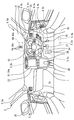
- a travel assist system 1 according to a first embodiment to which the present disclosure is applied is mounted on a vehicle 2 as shown in FIGS.
- the vehicle 2 to be mounted is referred to as a host vehicle 2 or a subject vehicle 2.
- the speed at which the host vehicle 2 travels is referred to as a vehicle speed
- the road on which the host vehicle 2 travels is referred to as a travel path
- the vehicle speed limited to the host vehicle 2 on the travel path is referred to as a speed limit.
- the travel assist system 1 includes a periphery monitoring system 3, a vehicle control system 4, and an information presentation system 5.
- the systems 3, 4, and 5 of the travel assist system 1 are connected via an in-vehicle network 6 such as a LAN (Local Area Network).
- LAN Local Area Network
- the periphery monitoring system 3 includes an external sensor 30 and a periphery monitoring ECU (Electronic Control Unit) 31.
- the outside sensor 30 detects obstacles that exist in the outside world of the host vehicle 2 and may collide, such as other vehicles, artificial structures, humans and animals, and traffic indications in the outside world.
- the external sensor 30 is, for example, one type or plural types of sonar, radar, camera, and the like.
- the sonar is an ultrasonic sensor installed in, for example, the front part or the rear part of the host vehicle 2.
- the sonar receives the reflected ultrasonic wave transmitted to the detection area in the external world of the host vehicle 2, thereby detecting an obstacle in the detection area and outputting a detection signal.
- the radar is a millimeter wave sensor or a laser sensor installed in, for example, the front part or the rear part of the host vehicle 2.
- the radar receives the millimeter wave or quasi-millimeter wave transmitted to the detection area in the outside world of the host vehicle 2 or the reflected wave of the laser, thereby detecting an obstacle in the detection area and outputting a detection signal. .
- the camera is a monocular or compound eye camera installed in, for example, a room mirror or a door mirror of the host vehicle 2.
- the camera captures a detection area in the outside world of the host vehicle 2 to detect an obstacle or traffic display in the detection area and outputs an image signal.
- the 2 is composed mainly of a microcomputer having a processor and a memory, and is connected to the external sensor 30 and the in-vehicle network 6.
- the surroundings monitoring ECU 31 uses, for example, sign information such as a speed limit sign, a stop sign, an intersection sign, an entrance / exit guide sign, a tunnel sign and a gradient sign, and lane marking information such as a white line and a yellow line based on an output signal of the external sensor 30. get.
- the periphery monitoring ECU 31 acquires obstacle information such as the type of the obstacle and the relative relationship of the obstacle with respect to the host vehicle 2 based on the output signal of the external sensor 30.
- an inter-vehicle distance, an inter-vehicle time, a relative speed, a predicted collision time (TTC: Time To Collision) and the like between the front vehicle as the front obstacle and the host vehicle 2 are determined by the peripheral monitoring ECU 31.
- the inter-vehicle time means a time obtained by dividing the inter-vehicle distance by the vehicle speed.
- TTC means a time obtained by dividing the inter-vehicle distance by the relative speed.
- the vehicle control system 4 includes a vehicle state sensor 40, an occupant sensor 41, and a vehicle control ECU 42.
- the vehicle state sensor 40 is connected to the in-vehicle network 6.
- the vehicle state sensor 40 detects the traveling state of the host vehicle 2.
- the vehicle state sensor 40 is, for example, one of a vehicle speed sensor, a rotation speed sensor, a wheel speed sensor, an acceleration sensor, a rudder angle sensor, an illuminance sensor, an outside air temperature sensor, a fuel sensor, a water temperature sensor, a battery sensor, a radio wave receiver, and the like. Or there are multiple types.
- the vehicle speed sensor detects the vehicle speed of the host vehicle 2 and outputs a vehicle speed signal corresponding to the detection.
- the rotation speed sensor detects the engine rotation speed in the host vehicle 2 and outputs a rotation speed signal corresponding to the detection.
- the wheel speed sensor outputs a wheel speed signal corresponding to the detection by detecting the rotational speed of the wheel in the host vehicle 2.
- the acceleration sensor outputs an acceleration signal according to the detection by detecting the acceleration acting on the host vehicle 2.
- the steering angle sensor detects the steering angle of the host vehicle 2 and outputs a steering angle signal corresponding to the detection.
- the illuminance sensor outputs an illuminance signal corresponding to the detection by detecting the illuminance in the external environment of the host vehicle 2.
- the outside air temperature sensor detects the outside air temperature of the host vehicle 2 and outputs an outside air temperature signal corresponding to the detection.
- the fuel sensor detects the remaining amount of fuel in the fuel tank of the host vehicle 2 and outputs a fuel signal corresponding to the detection.
- the water temperature sensor detects the coolant temperature of the internal combustion engine in the host vehicle 2 and outputs a water temperature signal corresponding to the detection.
- the battery sensor outputs a battery signal corresponding to the detection by detecting the remaining battery level of the host vehicle 2.
- the radio wave receiver receives an output radio wave from a roadside machine for road-to-vehicle communication, and outputs a weather signal related to weather information at the current or future travel position of the host vehicle 2, for example.
- the radio receiver outputs a traffic signal by receiving output radio waves from, for example, a positioning satellite, another vehicle transmitter for inter-vehicle communication, and a roadside unit for road-to-vehicle communication.
- the traffic signal is a signal representing the traffic information related to the host vehicle 2 such as the travel position, travel speed, travel time, travel path state, speed limit, and the like, and the obstacle information.
- the passenger sensor 41 is connected to the in-vehicle network 6.
- the occupant sensor 41 detects the state or operation of a user who has boarded the passenger compartment 2c of the host vehicle 2 shown in FIG.
- the occupant sensor 41 is, for example, one type or a plurality of types among a power switch, a user status monitor, a display setting switch, a light switch, a turn switch, a wiper switch, a shift switch, an inter-vehicle management switch, a cruise control switch, and the like.
- the power switch is turned on by the user in the passenger compartment 2c to start the internal combustion engine or the electric motor of the host vehicle 2, and outputs a power signal corresponding to the operation.
- the user state monitor captures the user state on the driver's seat 20 in the passenger compartment 2c with an image sensor, thereby detecting the user state and outputting an image signal.
- the display setting switch is operated by the user to set the display state in the passenger compartment 2c, and outputs a display setting signal corresponding to the operation.
- the light switch is turned on by the user in the passenger compartment 2c to turn on various lights of the host vehicle 2, and outputs a light signal corresponding to the operation.
- the turn switch is turned on by the user in the passenger compartment 2c to operate the direction indicator of the host vehicle 2, and outputs a turn signal corresponding to the operation.
- the wiper switch is turned on by the user in the passenger compartment 2c to operate the wiper of the host vehicle 2, and outputs a wiper signal corresponding to the operation.
- the shift switch detects the shift position of the shift lever 29 operated by the user in the passenger compartment 2c to change the shift state of the host vehicle 2, and outputs a shift signal corresponding to the detection.
- the inter-vehicle management switch is turned on by the user in the passenger compartment 2c in order to manage the inter-vehicle state of the host vehicle 2 with respect to the front vehicle traveling in the same direction on the same lane among the front obstacles. As a result, a management signal corresponding to the operation is output.
- the inter-vehicle state is a concept including the inter-vehicle distance and inter-vehicle time of the host vehicle 2 with respect to the preceding vehicle.
- the cruise control switch is turned on by the user in the passenger compartment 2c, and outputs a cruise signal corresponding to the operation.
- the inter-vehicle management switch and the cruise control switch can be selectively turned on. That is, the inter-vehicle management switch can be turned on when the cruise control switch is turned off.
- the inter-vehicle management of the present embodiment does not include the automatic control of the vehicle speed and the inter-vehicle distance of the host vehicle 2, and information that prompts the user to drive safely while the user is driving. Is presented according to the driving risk described later. Therefore, in the following, the state where the cruise control switch is turned off and the inter-vehicle management switch is turned on is referred to as “inter-vehicle management allowable state”.
- the vehicle control ECU 42 shown in FIG. 2 is mainly composed of a microcomputer having a processor and a memory, and is connected to the in-vehicle network 6.
- the vehicle control ECU 42 is one type or a plurality of types including at least an integrated control ECU among an engine control ECU, a motor control ECU, a brake control ECU, an integrated control ECU, and the like.
- the engine control ECU accelerates or decelerates the vehicle speed of the host vehicle 2 by controlling the operation of the throttle actuator and the fuel injection valve of the engine according to the operation of the accelerator pedal 26 (see FIG. 1) or automatically.
- the motor control ECU accelerates or decelerates the vehicle speed of the host vehicle 2 by controlling the operation of the motor generator according to the operation of the accelerator pedal 26 or automatically.
- the brake control ECU accelerates or decelerates the vehicle speed of the host vehicle 2 by controlling the operation of the brake actuator according to the operation of the brake pedal 27 (see FIG. 1) or automatically.
- the integrated control ECU synchronously controls the operation of the other control ECU based on, for example, the output signals of the sensors 40 and 41, the acquired information in the periphery monitoring ECU 31, the control information in the other control ECU as the vehicle control ECU 42, and the like.
- the integrated control ECU of the present embodiment provides a control command to the other control ECU as the vehicle control ECU 42 so as to automatically reduce or avoid the collision damage of the host vehicle 2 against the front obstacle such as the front vehicle. Operates as an “emergency control unit”.
- the integrated control ECU of the present embodiment realizes collision damage mitigation braking (AEB: Autonomous Emergency Braking) that automatically decelerates the vehicle speed of the host vehicle 2 when an emergency control condition is satisfied.
- AEB collision damage mitigation braking
- the emergency control condition for AEB is, for example, that TTC approaches 5 seconds or less.
- the integrated control ECU of this embodiment when the cruise control switch is turned on by the user, the full vehicle speed range adaptive cruise control (FSRA) that automatically controls the inter-vehicle distance or the vehicle speed in the full vehicle speed range of the host vehicle 2. Full Speed Range Adaptive Cruise Control) is realized.
- the FSRA functions so that the vehicle speed of the host vehicle 2 becomes the speed set by the user.
- the integrated control ECU makes the inter-vehicle distance of the host vehicle 2 with respect to the preceding vehicle equal to or greater than the user-set distance and the vehicle speed of the host vehicle 2 is equal to or less than the user-set speed.
- the inter-vehicle distance set by the user changes according to the vehicle speed of the host vehicle 2. For example, when the host vehicle 2 normally travels on an expressway, the distance between the host vehicle 2 and the preceding vehicle is 60 m or more (2 seconds or more in the inter-vehicle time), or the host vehicle 2 has a vehicle speed of 100 km / h or less.
- FSRA functions.
- AEB is executed when an emergency control condition is satisfied regardless of the state of the cruise control switch or the state of the inter-vehicle management switch. That is, if the emergency control condition (for example, TTC) satisfies the condition, the AEB is executed as an interruption process even when the FSRA and the inter-vehicle management are being executed, and the functions of the FFSRA and the inter-vehicle management are stopped during the execution of the AEB.
- TTC emergency control condition
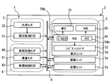
- the information presentation system 5 is a combination of the acoustic unit 5s, the vibration unit 5v, and the display unit 5d, and causes these units 5s, 5v, and 5d to function as “information presentation units”, respectively.
- the acoustic unit 5s is mounted on the host vehicle 2 in order to present information in an auditory manner.
- the acoustic unit 5s is mainly composed of a speaker and a sound source circuit, and is connected to the in-vehicle network 6.
- the acoustic unit 5s is installed, for example, in one or a plurality of locations of the driver seat 20, the instrument panel 22, and the door 25 in the passenger compartment 2c of the host vehicle 2 shown in FIG. A perceptible sound wave or sound is generated.
- the vibration unit 5v shown in FIG. 2 is mounted on the host vehicle 2 for tactile presentation of information.
- the vibration unit 5v is mainly composed of a vibration actuator, and is connected to the in-vehicle network 6.
- the vibration unit 5v is installed, for example, in one or a plurality of locations of the driver's seat 20, the steering handle 24, the accelerator pedal 26, the brake pedal 27, and the footrest 28 in the passenger compartment 2c shown in FIG. An alarm vibration that can be perceived by the user is generated.
- the display unit 5d shown in FIG. 2 is mounted on the host vehicle 2 for visually presenting information.
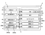
- the display unit 5 d includes an HUD (Head-up Display) 50, an MFD (Multi-Function Display) 51, a combination meter 52, and an HCU (HMI (Human Machine Interface) Control Unit) 54.
- HUD Head-up Display
- MFD Multi-Function Display
- HCU HMI (Human Machine Interface) Control Unit) 54.
- the HUD 50 is installed on the instrument panel 22 in the passenger compartment 2c shown in FIG.
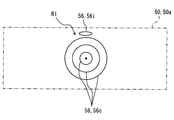
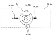
- the HUD 50 projects the image 56 formed so as to show predetermined information on the liquid crystal panel or the projection screen onto the windshield 21 of the host vehicle 2 so that the virtual image of the image 56 can be visually recognized by the user on the driver's seat 20. indicate.
- the virtual image display by the HUD 50 is visually recognized by the user in a display range 50 a having a predetermined area that is a projection range of the image 56 onto the windshield 21, overlapping with an external scene in front of the host vehicle 2.
- the display of the attention image 56c and the notification image 56i as shown in FIGS.
- the virtual image display by the HUD 50 in addition to the images 56c and 56i, for example, an image display indicating one type or a plurality of types of information among navigation information, sign information, obstacle information, and the like may be adopted.
- an image display indicating one type or a plurality of types of information among navigation information, sign information, obstacle information, and the like may be adopted.
- a virtual image display can also be realized by projecting the image 56 on the combiner.
- the navigation information can be acquired based on the map information stored in the memory 54m and the output signal of the sensor 40, for example, in the HCU 54 described in detail later.
- the MFD 51 is installed in the center console 23 in the passenger compartment 2c shown in FIG.
- the MFD 51 displays a real image of the image 56 formed so as to show predetermined information on one or a plurality of liquid crystal panels so that the user on the driver's seat 20 can visually recognize the image.
- the real image display by the MFD 51 is visually recognized by the user in the display range 51 a having a larger area than the display range 50 a of the HUD 50.
- an image display indicating one type or a plurality of types of information among navigation information, audio information, video information, communication information, and the like is employed.
- the combination meter 52 is installed on the instrument panel 22 in the passenger compartment 2c.
- the combination meter 52 displays vehicle information related to the host vehicle 2 so that the user on the driver's seat 20 can visually recognize the vehicle information.
- the combination meter 52 is a digital meter that displays vehicle information by an image formed on a liquid crystal panel, or an analog meter that displays vehicle information by indicating a scale with a pointer.
- Such display by the combination meter 52 includes, for example, vehicle speed, engine speed, fuel remaining amount, cooling water temperature, battery remaining amount, operation state of light switch, turn switch, shift switch, inter-vehicle management switch and cruise control switch, etc. Of these, a display indicating one type or a plurality of types of information is employed.
- the HCU 54 is also referred to as an electronic control unit.
- the HCU 54 is configured mainly by a microcomputer having a processor 54p and a memory 54m as an example, and the display elements 50, 51, 52 of the display unit 5d. And in-vehicle network 6.
- the HCU 54 controls the operations of the acoustic unit 5s and the vibration unit 5v and the operations of the display elements 50, 51, and 52 of the display unit 5d in synchronization.
- the HCU 54 controls the operation thereof based on, for example, output signals of the sensors 40 and 41, acquisition information in the ECU 31, control information in the ECU 42, storage information in the memory 54m, and acquisition information including time information of the HCU 54 itself.
- the HCU 54 functions as a “vehicle distance management device” (or also referred to as “vehicle distance control device”) in order to realize vehicle distance management, details thereof will be described below.
- the functions realized by the processor 54p may be realized by a plurality of processors.
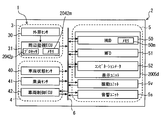
- the HCU 54 functionally constructs a plurality of blocks 541, 542, 543, and 544 as shown in FIG. 6 by executing the inter-vehicle management program by the processor 54p. These blocks are also referred to as parts, devices, modules, units. Of course, at least a part of these blocks 541, 542, 543, and 544 may be constructed in hardware by one or a plurality of ICs.
- the scene estimation block 541 as the “scene estimation unit” estimates the driving scene of the host vehicle 2 by the user based on the scene information acquired by the information acquisition block 542.
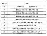
- the driving scene estimated by the scene estimation block 541 includes at least scenes D0, D1, D2, D3, D4, D5, D6, D7, and D8, as shown in FIG.
- Scene D0 is a driving scene that requires inter-vehicle management.
- the scene D0 is a follow-up traveling state in which the host vehicle 2 travels in the same direction on the same lane behind the front vehicle under the inter-vehicle management permission state before the AEB operation by the integrated control ECU. This is the situation.
- the following traveling state constituting the scene D0 is a state where the vehicle speed is equal to or higher than the threshold value V0 and the inter-vehicle distance is less than the threshold value L0 (see FIGS. 10 and 12).
- the scene information necessary for the assumption of the scene D0 includes the vehicle speed, the inter-vehicle distance as obstacle information, the AEB operating state, the cruise control switch operating state (ie, the FSRA operating state), and the inter-vehicle management switch operating state. Is adopted.
- said threshold value V0 is set to values, such as 10 km / h, as a boundary value for distinguishing from the vehicle speed at the time of slowing at which the driving risk of the host vehicle 2 by a user falls.
- said threshold value L0 is set to values, such as 100m, as a boundary value for distinguishing from the independent driving
- Scene D1 is a driving scene in which an illusion of information necessary for driving the host vehicle 2 is generated, which may cause an error in user judgment or user feeling regarding driving risk.
- a scene D1 is a situation where the user's perceived speed is likely to deviate from the vehicle speed, for example, a situation where the travel path is switched from a highway to a general road, a situation where the travel path is in a tunnel, and a travel path is a sag section.
- Examples of the scene information necessary for the assumption of the scene D1 include one of sign information, traffic information, navigation information, vehicle speed, acceleration, engine speed, illuminance, user state, and operation state of the turn switch and the light switch. Types or multiple types are adopted.
- the expressway mentioned above means a traveling road having a legal maximum speed, which is the maximum value of the speed limit legally defined by the competent authority, higher than that of a general road.
- said tunnel means the traveling path formed, for example, digging a mountain or the underground etc., and the thing which can be imitated as the said traveling path is also included.
- the sag portion means a section where the gradient of the travel path gradually changes from the down direction to the up direction.
- Scene D2 is a driving scene that is expected to cause a delay in user judgment regarding driving risk due to a lack of information necessary for driving the host vehicle 2.
- the scene D2 there is a structure in front of the user due to a situation where a blind spot is formed with respect to the user, for example, a situation where the traveling road is the top of an uphill, a curve or intersection of the traveling road. This is the situation and the situation where a parked vehicle or a large vehicle exists in front of the road.
- the scene D2 is also a situation in which the user's visibility is reduced due to factors such as rain, snow, fog, backlight, dazzling light, or night driving.
- said top part means the area where the gradient of a traveling path changes gradually from an up direction to a down direction.
- Scene D3 is a driving scene that is assumed to cause an error in user judgment regarding driving risk due to an increase in information necessary for driving the host vehicle 2.
- the scene D3 is a situation in which multi-directional safety confirmation is required, for example, by entering an intersection.
- the scene information necessary for the assumption of such a scene D3 for example, one type or a plurality of types are adopted among sign information, traffic information, navigation information, and the like.
- Scene D4 is a driving scene that is likely to cause an error in user judgment on driving risk due to an increase in operational tasks necessary for driving the host vehicle 2.
- the scene D4 is a situation in which the traveling direction of the host vehicle 2 changes due to, for example, a right turn, a left turn, or a turn of the traveling road.
- scene information necessary for the assumption of such a scene D4 for example, one type or a plurality of types among sign information, lane marking information, traffic information, navigation information, user status, vehicle speed, steering angle, and turn switch operation status, etc. Is adopted.
- Scene D5 is a driving scene in which the driving risk is likely to increase due to the host vehicle 2 being accelerated or obstructed by natural action.
- the scene D5 is a situation in which the host vehicle 2 accelerates due to, for example, a downhill road.
- the scene D5 is also a situation where deceleration of the host vehicle 2 is hindered, for example, a situation where the traveling road is a low ⁇ road due to factors such as ice burn, unpaved, snow or rain.
- the scene information necessary for the assumption of the scene D5 includes, for example, sign information, traffic information, navigation information, vehicle speed, acceleration, engine speed, weather information, outside air temperature, wheel rotational speed, and wiper switch operation state.
- the low ⁇ road means a traveling road where the slip coefficient of the road surface is increased due to a low sliding friction coefficient of the road surface with respect to the wheel of the host vehicle 2.
- Scene D6 is a driving scene in which driving risk increases when the vehicle speed of the host vehicle 2 is equal to or higher than the safe speed Vs.
- the safe speed Vs is a vehicle speed necessary for ensuring the safety of the host vehicle 2 in terms of driving risk.
- the speed limit including the legal maximum speed, or the speed limit is calculated based on the sliding friction coefficient of the road, weather, and the like. It is set to a speed corrected in consideration of information or a user state.
- Examples of scene information necessary to assume the scene D6 based on the safe speed Vs include obstacle information, lane marking information, sign information, traffic information, navigation information, vehicle speed, engine speed, weather information, and outside temperature.
- One type or a plurality of types are adopted among the wheel rotation speed and the operation states of the pedals 26 and 27 and the wiper switch.
- Scene D7 is a driving scene in which driving risk increases when the inter-vehicle distance between the host vehicle 2 and the preceding vehicle is equal to or less than the safe distance Ls on driving risk.
- the safety distance Ls is an inter-vehicle distance necessary for ensuring the safety of the host vehicle 2 in terms of driving risk.
- the shortest braking distance according to the vehicle speed, or the shortest braking distance is the sliding friction coefficient of the traveling road. The distance is corrected in consideration of weather information or user status.
- Examples of scene information necessary to assume the scene D7 based on the safety distance Ls include obstacle information, lane marking information, sign information, traffic information, navigation information, vehicle speed, engine speed, weather information, and outside temperature.
- One type or a plurality of types are adopted among the wheel rotation speed and the operation states of the pedals 26 and 27 and the wiper switch.
- Scene D8 is a driving scene in which the driving risk increases when the inter-vehicle time between the host vehicle 2 and the preceding vehicle is equal to or less than the safety time Ts in terms of driving risk.
- the safety time Ts is an inter-vehicle time necessary for ensuring the safety of the host vehicle 2 in terms of driving risk. For example, 2 to 3 in consideration of the sliding friction coefficient of the travel road, weather information, or the user condition. Set to a value such as seconds.
- scene information necessary to assume the scene D8 based on the safety time Ts include obstacle information, lane marking information, sign information, traffic information, navigation information, vehicle speed, engine speed, time information, and weather information.
- One type or a plurality of types are adopted among the outside air temperature, the wheel rotation speed, and the operation states of the pedals 26 and 27 and the wiper switch.
- An information acquisition block 542 shown in FIG. 6 as a “scene information acquisition unit” acquires information necessary for estimation of a driving scene by the scene estimation block 541 as scene information related to the driving scene of the host vehicle 2. At this time, the information acquisition block 542 realizes information acquisition based on the output signals of the sensors 40 and 41, the control information in the vehicle control ECU 42, and the acquisition information in the periphery monitoring ECU 31 and the HCU 54.
- the information acquisition necessary for the assumption of the scene D0 is based on the acquisition information in the peripheral monitoring ECU 31, the control information in the integrated control ECU, and the output signals of the vehicle speed sensor, the cruise control switch, and the inter-vehicle management switch.
- Information acquisition necessary for the assumption of the scene D1 includes, for example, acquisition information in the peripheral monitoring ECU 31 and the HCU 54 (hereinafter, collectively referred to as control elements 31, 54), a radio wave receiver, a vehicle speed sensor, an acceleration sensor, a rotation Based on one or a plurality of types of output signals from a number sensor, illuminance sensor, user status monitor, turn switch, and light switch.
- Information necessary for the assumption of the scene D2 includes, for example, information acquired by the control elements 31 and 54, a radio wave receiver, a vehicle speed sensor, an acceleration sensor, a rotation speed sensor, an illuminance sensor, an outside air temperature sensor, a steering angle sensor, and a wiper switch. And based on one or more types of output signals of the light switch.
- Information acquisition necessary for the assumption of the scene D3 is based on one type or a plurality of types of information acquired by the control elements 31 and 54, an output signal of the radio receiver, and the like.
- Information acquisition necessary for the assumption of the scene D4 is, for example, one of the acquisition information in the control elements 31 and 54, and the radio receiver, the user state monitor, the vehicle speed sensor, the steering angle sensor, the output signal of the turn switch, and the like. Based on multiple types.
- Information acquisition necessary for the assumption of the scene D5 includes, for example, acquisition information in the control elements 31 and 54, and output signals of radio wave receivers, vehicle speed sensors, acceleration sensors, rotation speed sensors, outside air temperature sensors, wheel speed sensors, and wiper switches. Etc., based on one or more types.
- Information acquisition necessary for the assumption of the scene D6 includes, for example, acquisition information in the control elements 31 and 54, control information of the engine control ECU, motor control ECU, and brake control ECU, a radio wave receiver, a vehicle speed sensor, a rotation speed sensor, Based on one type or a plurality of types of output signals from the air temperature sensor, the wheel speed sensor, the wiper switch, and the like.
- the information acquisition necessary for the assumption of the scene D7 and the information acquisition necessary for the assumption of the scene D8 are the same as the information acquisition necessary for the assumption of the scene D6.
- the information acquisition block 542 that also functions as the “behavior information acquisition unit” displays the behavior information related to the driving behavior of the host vehicle 2 by the user, the output signals of the sensors 40 and 41, and the vehicle control. Obtained based on control information in the ECU 42.
- control information in the ECU 42 attention is paid to the operation states of the pedals 26 and 27 and the shift lever 29 as the action information related to the deceleration action that ensures the safety of the host vehicle 2 among the driving actions. Therefore, the acquisition of such behavior information is based on one or more types of control information in the engine control ECU or motor control ECU, control information in the brake control ECU, and output signals from the vehicle speed sensor and the shift switch. become.
- the risk determination block 543 determines the driving risk based on the driving scene estimated by the scene estimation block 541 and the action information acquired by the information acquisition block 542.
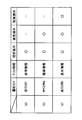
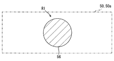
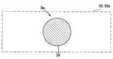
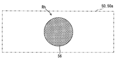
- the risk determination block 543 includes a plurality of sub-blocks 545, 546, 547, and 548 in order to make a determination of the low risk Rl, the medium risk Rm, and the high risk Rh.
- the driving risk is the low risk Rl. Judgment is made. For example, as illustrated in FIG. 8A, the driving risk with the factor C1 as the scene D5 in which the traveling path is a downhill is a low risk Rl. Further, as illustrated in FIG. 8B, the driving risk with the factor C1 as the scene D2 in which the large vehicle exists as the front vehicle is also a low risk Rl.
- the middle determination subblock 546 illustrated in FIG. 8C a driving risk with a scene D5 having a downhill traveling path as a factor C1 and a scene D7 having an inter-vehicle distance equal to or less than the safety distance Ls as a factor C2 is a medium risk. Rm.
- FIG. 8C a driving risk with a scene D5 having a downhill traveling path as a factor C1 and a scene D7 having an inter-vehicle distance equal to or less than the safety distance Ls as a factor C2 is a medium risk. Rm.
- the driving risk with a scene D2 in which a large vehicle exists as a forward vehicle as a factor C1 and a scene D7 in which the inter-vehicle distance is equal to or less than the safety distance Ls is also a factor C2, Risk Rm.
- the high determination sub-block 547 shown in FIG. 6 first estimates the driving behavior for the risks Rl and Rm based on the behavior information acquired by the information acquisition block 542. Further, the high determination sub-block 547 determines that the driving risk is a high risk Rh higher than the medium risk Rm when the estimated driving behavior does not reduce the driving risk. For example, as illustrated in FIG. 8E, in addition to the same factors C1 and C2 as in FIG. 8C, the driving risk with acceleration behavior or constant velocity behavior as the factor C3 is a high risk Rh. . Further, as illustrated in FIG. 8F, in addition to the same factors C1 and C2 as in FIG. 8D, the driving risk with acceleration behavior or constant velocity behavior as the factor C3 is also a high risk Rh. .
- the final determination sub-block 548 shown in FIG. 6 makes a final determination of the driving risk based on the determination results of the other sub-blocks 545, 546 and 547.
- the final determination result is determined to be low risk Rl.
- the high risk Rh is not determined by the high determination sub-block 547. Determines the final determination result to the medium risk Rm.
- the final determination result is determined as high risk Rh.
- the information presentation control block 544 controls the presentation of assist information by the information presentation system 5 in order to prompt the user to deal with the driving risk determined by the risk determination block 543.
- the presentation of the assist information is controlled on the condition that the scene D0 as the driving scene is estimated by the scene estimation block 541. That is, when the driving scene estimated by the scene estimation block 541 is the following traveling state of the host vehicle 2, assist information is presented before the AEB is activated.
- the assist information to be presented is selected from the reference information, the proposal information, and the request information illustrated in FIG. 9 according to the level of the driving risk finally determined by the final determination sub-block 548.
- the assist information corresponding to the low risk Rl as the final determination result is selected by the information presentation control block 544 to make the user aware of the driving risk that is a reference in determining the driving behavior, and the information presentation system 5 Reference information presented by As a presentation mode of the reference information, visual presentation by the display unit 5d is adopted as shown in FIG.
- a virtual image display of the caution image 56 c and the notification image 56 i by the HUD 50 is employed as visual presentation.
- the example caution image 56c is a plurality of circular images displayed on concentric circles, and indicates the level of the caution level according to the driving risk depending on the radius of the outer peripheral contour line.
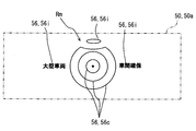
- the example notification image 56i is an oval image displayed above the entire caution image 56c. For example, the caution level for a front obstacle such as a large vehicle in FIG. Shown by relationship.
- the assist information corresponding to the medium risk Rm as the final determination result is proposed information that is selected by the information presentation control block 544 and presented by the information presentation system 5 in order to propose to the user a driving action that suppresses an increase in driving risk. It is.
- a presentation mode of the proposal information auditory presentation by the acoustic unit 5s is adopted as shown in FIG. 9B together with visual presentation by the display unit 5d.
- the virtual image display of the attention image 56 c and the notification image 56 i by the HUD 50 is employed as visual presentation.
- the exemplary notification image 56i includes an ellipse image representing a front obstacle, a character image indicating a proposed driving action, and a character indicating a driving risk factor C1 such as the large vehicle in FIG. 8C. It is with an image.
- the attention image 56 c having the outer peripheral contour line with the maximum radius is deformed as the attention level with respect to the front obstacle increases.
- the auditory presentation added to the visual presentation of these images 56c and 56i for example, one of the information generated from the acoustic unit 5s among the intermittent notification sound wave and the notification sound suggesting attention to deceleration or driving risk. Types or multiple types are adopted.
- the assist information corresponding to the high risk Rh as the final determination result is request information that is selected by the information presentation control block 544 and presented by the information presentation system 5 in order to request the user to drive behavior that reduces the driving risk. is there.
- request information As the presentation form of the request information, auditory presentation by the acoustic unit 5s and tactile presentation by the vibration unit 5v are adopted as shown in FIG. 9C, along with visual presentation by the display unit 5d.
- the virtual image display of the caution image 56 c and the notification image 56 i by the HUD 50 is employed as visual presentation.
- the exemplary notification image 56i includes an ellipse image representing a front obstacle, a character image indicating a requested driving action, and a character indicating a driving risk factor C1 such as the large vehicle in FIG. It is an image.
- the attention image 56c having the outer peripheral contour with the maximum radius is deformed together with the attention image 56c having the outer peripheral contour with the maximum radius in accordance with the increase in the attention level with respect to the front obstacle.
- the auditory presentation added to the visual presentation of the images 56c and 56i for example, one type or a plurality of types generated from the acoustic unit 5s among continuous notification sound waves and notification sound requesting braking or down-shifting, etc. kind is adopted.
- a notification vibration at the installation destination of the vibration unit 5v is employed.
- the images 56c and 56i stored as data in the memory 54m of the HCU 54 are read out and displayed as virtual images by the HUD 50 in any visual presentation of reference information, proposal information, and request information.
- the memory 54m of the HCU 54 and the memories of other various ECUs are respectively configured by using one or a plurality of storage media such as a semiconductor memory, a magnetic medium, or an optical medium.
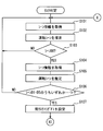
- the risk determination procedure in FIGS. 10 and 11 and the presentation control procedure in FIG. 12 are realized as the “inter-vehicle management method”. This will be described below.
- the risk determination procedure and the presentation control procedure are started in response to an ON operation of a power switch as the occupant sensor 41 and are ended in response to an OFF operation of the switch.
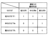
- the values of the low risk flag Fl, the medium risk flag Fm, and the high risk flag Fh set in the memory 54m as shown in FIG. 13 are set to “0”. Initializing.
- “S” in the risk determination procedure and the presentation control procedure means each section or step.
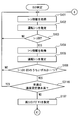
- the risk judgment procedure will be described.
- scene information necessary for assuming the scene D ⁇ b> 0 is acquired by the information acquisition block 542.
- the current driving scene is estimated by the scene estimation block 541 based on the scene information acquired in S101.
- the information presentation control block 544 determines whether or not the current driving scene estimated in S102 is the scene D0. As a result, if a negative determination is made, the process returns to S101.
- S104 scene information necessary for assuming the scenes D1, D2, D3, D4, and D5 is acquired by the information acquisition block 542.
- the current driving scene is estimated by the scene estimation block 541 based on the scene information acquired in S102.
- the low determination sub-block 545 in the risk determination block 543 determines whether the current driving scene estimated in S105 is any one of the scenes D1, D2, D3, D4, and D5. To do. As a result, if a negative determination is made, the process returns to S101. On the other hand, if a positive determination is made that means that the driving risk is the low risk Rl, the process proceeds to S107. In S107, the value of the low risk flag Fl (see FIG. 13) in the memory 54m is set to “1” by the low determination sub-block 545.
- the process proceeds to S108 as shown in FIG.
- the information acquisition block 542 acquires scene information necessary for the assumption of the scenes D6, D7, and D8.
- the current driving scene is estimated by the scene estimation block 541 based on the scene information acquired in S108.
- the middle determination sub-block 546 in the risk determination block 543 determines whether or not the current driving scene estimated in S108 is at least one of the scenes D6, D7, and D8. As a result, if a negative determination is made, the process returns to S101. On the other hand, if a positive determination is made that the driving risk is the medium risk Rm, the process proceeds to S111.
- the value of the medium risk flag Fm (see FIG. 13) in the memory 54m is set to “1” by the medium determination sub-block 546.
- the process proceeds to S112.
- S ⁇ b> 112 behavior information necessary for assuming the current driving behavior is acquired by the information acquisition block 542.
- the current driving behavior based on the behavior information acquired in S112 is estimated by the high determination sub-block 547 in the risk determination block 543.
- the high determination sub-block 547 determines whether or not the driving behavior estimated in S113 is a behavior that reduces the driving risk. As a result, when a positive determination is made, the process returns to S101. On the other hand, if the driving action does not reduce the driving risk and a negative determination is made, the process proceeds to S115.
- the value of the high risk flag Fh (see FIG. 13) in the memory 54m is set to “1” by the high determination sub-block 547, and the process returns to S101.
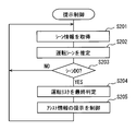
- S201 of the presentation control procedure scene information necessary for the assumption of the scene D0 is acquired by the information acquisition block 542.
- the current driving scene is estimated by the scene estimation block 541 based on the scene information acquired in S201.
- the information presentation control block 544 determines whether or not the current driving scene estimated in S202 is the scene D0. As a result, if a negative determination is made, the process returns to S201. On the other hand, if a positive determination is made, the process proceeds to S204.
- the final determination subblock 548 of the risk determination block 543 finally determines the current driving risk according to the values of the risk flags Fl, Fm, and Fh set in the memory 54m. Specifically, as shown in FIG. 13, when the values of the risk flags Fl, Fm, and Fh are “1”, “0”, and “0”, respectively, the final determination result is determined as the low risk Rl. . When the values of the risk flags Fl, Fm, and Fh are “1”, “1”, and “0”, respectively, the final determination result is determined as the medium risk Rm. Furthermore, when the values of the risk flags Fl, Fm, and Fh are “1”, “1”, and “1”, respectively, the final determination result is determined as the high risk Rh.
- S101, S104, S108, and S201 correspond to “scene information acquisition step”
- S102, S105, S109, and S202 correspond to “scene estimation step”
- S112 corresponds to “behavior information acquisition step”.
- S106, S107, S110, S111, S113, S114, S115, and S204 correspond to “risk determination step”
- S103, S203, and S205 correspond to “presentation control step”.
- the assist information that prompts the user to deal with the driving risk is selected according to the level of the driving risk.
- the driving risk is determined based on the driving scene estimated based on the scene information and the action information related to the driving action.
- the assist information for managing the inter-vehicle condition is presented according to the level of the driving risk according to the driving scene and driving behavior. Can be secured.
- the assist information selected and presented by the information presentation unit corresponds to the driving risk determined based on the driving scene and the behavior information among the reference information, the proposal information, and the request information.
- the reference information corresponding to the low risk Rl as the driving risk is presented, the user is made aware of the driving risk that is used as a reference in determining the driving behavior, and the sensitivity to ensuring safety is at an early stage. It becomes possible to raise from.
- the proposed information corresponding to the medium risk Rm higher than the low risk Rl is presented as the driving risk, the driving action that suppresses the increase of the driving risk is proposed to the user, and the concrete for ensuring safety It is possible to provide objective and objective indicators.
- the requirement information corresponding to the high risk Rh higher than the medium risk Rm being presented as the driving risk the user is requested to drive the action to reduce the driving risk, and the safety for the imminent danger is ensured. It is possible to strongly encourage.
- the determined driving risk is the low risk Rl
- visual presentation by the display unit 5d is adopted as the presentation mode of the selected reference information.
- the determined driving risk is the medium risk Rm
- visual presentation by the display unit 5d (HUD50) and auditory presentation by the acoustic unit 5s are adopted as presentation modes of the proposal information to be selected.
- the user grasps a specific and objective index corresponding to an increase in driving risk by visual recognition of the proposed information visually presented and auditory recognition of the same information presented auditorily, to ensure safety.
- the presentation mode of the proposal information to be selected includes visual presentation by the display unit 5d (HUD50), auditory presentation by the acoustic unit 5s, and tactile presentation by the vibration unit 5v. And are adopted.
- HUD50 display unit 5d
- auditory presentation by the acoustic unit 5s auditory presentation by the acoustic unit 5s
- tactile presentation by the vibration unit 5v tactile presentation by the vibration unit 5v.
- the user is strongly conscious of ensuring safety against imminent danger by adding auditory recognition by auditory presentation and tactile recognition by tactile presentation to the request information that is visually presented and recognized.
- the driving action to be reduced can be taken surely.
- the driving risk is the low risk Rl. Is done. According to this, even if an illusion, omission, or increase in information necessary for driving the host vehicle 2 occurs, the sensitivity of the user to ensuring safety can be increased by presenting the reference information. Moreover, even if the operational tasks necessary for driving the host vehicle 2 increase, the user's sensitivity to ensuring safety can be increased by presenting the reference information. Furthermore, even if the host vehicle 2 is accelerated or obstructed by a natural action, the sensitivity of the user to ensuring safety can be increased by presenting the reference information.
- the driving risk is the medium risk Rm.
- the user grasps the specific and objective index for ensuring safety by presenting the proposal information, and the driving risk You can take driving action to suppress the rise of
- the user can grasp a specific and objective index for ensuring safety by presenting the proposal information, and You can take driving action that suppresses the increase in driving risk.
- the user can grasp a specific and objective index for ensuring safety by presenting the proposal information, It is possible to take driving action that suppresses the increase in driving risk.
- the driving risk is a high risk Rh. A decision is made. According to this, even if the driving behavior is not appropriate for the imminent danger, the user can appropriately take the driving behavior that reduces the driving risk in order to ensure safety according to the presented request information.
- the second embodiment of the present disclosure is a modification of the first embodiment.
- the display unit 2005d of the second embodiment is not provided with the HCU 54. Therefore, in the second embodiment, the vehicle control ECU 2042 such as an integrated control ECU is caused to function as the “inter-vehicle management device”. Thereby, the processor 2042p of the vehicle control ECU 2042 executes the inter-vehicle management program, thereby constructing a plurality of blocks 541, 542, 543, and 544, and each procedure as the “inter-vehicle management method” is the same as in the first embodiment. To be realized.
- the risk flags Fl, Fm, Fh are set in, for example, a memory 2042m provided in the vehicle control ECU 2042 serving as a “vehicle distance management device”.
- the data of the images 56c and 56i are stored in, for example, the memory 2042m of the vehicle control ECU 2042 or the memory 50m provided in the HUD 50.
- the other configurations of the vehicle control ECU 2042 and the HUD 50 are the same as those in the first embodiment.
- the third embodiment of the present disclosure is a modification of the first embodiment.
- the low risk flag Fl is set and the reference information is visually presented.
- driving scenes D1, D2, D3, D4, and D5 frequently occur in daily life, the user may feel annoying when the low risk flag Fl is set and presented visually each time.
- the reference information is presented visually even though the user is driving in consideration of the vehicle speed, there is a risk that the user may feel more troublesome. Therefore, in the third embodiment, this problem is solved by limiting the setting condition of the low risk flag Fl in risk determination.
- the current vehicle speed is less than a predetermined speed setting value.
- S3116 for determining whether or not is provided. If the current vehicle speed is less than the speed set value in S3116, the process returns to S101. On the other hand, if the current vehicle speed is equal to or higher than the speed set value, the process proceeds to S107 and the low risk flag Fl is set.
- the speed threshold is set so that the above-described safe speed Vs is also low. For example, when the safe speed Vs is the limit speed of 60 km / h, the speed threshold is set to 40 km / h.
- S106, S107, S108, S109, S110, S112, S113, S114, S115, S204, and S3116 correspond to the “risk determination step”.
- the visual presentation of unnecessary reference information is suppressed by limiting the setting conditions of the low risk flag Fl.
- the low risk flag instead of setting the low risk flag, it is presented by the presentation control in FIG. These conditions may be set.
- S205 of FIG. 12 the same effect can be obtained even if a condition whether the speed is less than the safe speed is incorporated as the reference information presentation condition.
- the driving risk may be divided into a plurality of stages other than the three stages, and assist information corresponding to each risk may be presented. For example, by adopting only two stages of low risk Rl, medium risk Rm, and high risk Rh as driving risks, two types corresponding to the adoption risk may be presented among reference information, proposal information, and request information. Good.
- each presentation mode of the reference information, the proposal information, and the request information may be selected according to the operation of the display setting switch as the occupant sensor 41.
- visual presentation by at least one of the MFD 51 and the combination meter 52 may be adopted.
- assist information may be visually presented by an image different from the caution image 56c and the notification image 56i.
- the reference information is visually presented by a green image 56 indicated by right-upward hatching
- the proposal information is visually presented by a yellow image 56 indicated by left-upward hatching, and is shown by cross-hatching.
- a modified example 7 in which the request information is visually presented by a red image 56 is shown.
- Modification 10 in order to determine the medium risk Rm, only some of the driving scenes among the scenes D6, D7, and D8 may be estimated.
- modification 11 in order to determine the medium risk Rm, other driving scenes may be estimated instead of or in addition to at least one of the scenes D6, D7, and D8.
- the medium risk Rm when at least two of the scenes D6, D7, and D8 are estimated, or when all of the scenes D6, D7, and D8 are estimated, the medium risk Rm may be determined.
- the driving scene to be estimated for determining the low risk Rl and the medium risk Rm may be selected according to the operation of the display setting switch.
- the integrated control ECU when the emergency control condition is satisfied, the integrated control ECU is operated as an “emergency control unit” in order to reduce or avoid the collision damage of the host vehicle 2 against the obstacle ahead, and an emergency warning (FCW : Front Collision Warning) may be executed by the information presentation system 5.
- FCW Front Collision Warning
- the emergency control condition of FCW is that TTC approaches 10 seconds or less, for example. Therefore, in the modified example 15 in which both the AEB and the FCW are realized by the integrated control ECU, the host vehicle 2 is in the following traveling state under the inter-vehicle management allowable state before the operation of at least one of the AEB and the FCW. A scene D0 is used. On the other hand, in the modified example 15 in which only the FCW is realized by the integrated control ECU, a scene D0 in which the host vehicle 2 is in the following traveling state under the inter-vehicle management allowable state before the FCW operation is employed.
- the inter-vehicle management allowable state may be realized only by turning on the inter-vehicle management switch before the AEB operation without providing the cruise control switch.
- the inter-vehicle management permission state may be automatically realized by turning off the cruise control switch before the AEB operation without providing the inter-vehicle management switch.
- the inter-vehicle management allowable state may be automatically realized before the AEB operation without providing the cruise control switch and the inter-vehicle management switch.
- only the inter-vehicle distance less than the threshold value L0 may be adopted as the condition for the follow-up running state without adopting the vehicle speed equal to or higher than the threshold value V0.
- one type or a plurality of types of the display ECU provided for controlling the display elements 50, 51, and 52 and the surrounding monitoring ECU 31 are set as “vehicle distance”. It may function as a “management device”. That is, the blocks 541, 542, 543, and 544 may be constructed by the processors of one or more types of ECUs, and each procedure as the “vehicle distance management method” may be realized.
- FIG. 17 shows a modified example 20 in the case where the periphery monitoring ECU 31 including the processor 2042p and the memory 2042m described in the second embodiment fulfills the function of the “vehicle distance management device”.
- the adaptive cruise control for automatically controlling the inter-vehicle distance or the vehicle speed in a specific vehicle speed range such as a high-speed range can be realized. Good.
Landscapes
- Engineering & Computer Science (AREA)
- Automation & Control Theory (AREA)
- Mechanical Engineering (AREA)
- Transportation (AREA)
- Physics & Mathematics (AREA)
- General Physics & Mathematics (AREA)
- Human Computer Interaction (AREA)
- Combustion & Propulsion (AREA)
- Chemical & Material Sciences (AREA)
- Traffic Control Systems (AREA)
- Control Of Driving Devices And Active Controlling Of Vehicle (AREA)
- Aviation & Aerospace Engineering (AREA)
- Radar, Positioning & Navigation (AREA)
- Remote Sensing (AREA)
- Controls For Constant Speed Travelling (AREA)
Abstract
La présente invention concerne un dispositif de gestion inter-véhicule (54) pourvu d'une unité d'acquisition d'informations de scène (542) permettant d'acquérir des informations de scène relatives à la scène d'entraînement d'un véhicule hôte, une unité d'estimation de scène (541) permettant d'estimer la scène d'entraînement sur la base des informations de scène acquises, une unité d'acquisition d'informations de comportement (542) permettant d'acquérir des informations de comportement concernant le comportement de conduite d'un utilisateur, une unité de détermination de risque (543) permettant de déterminer le risque d'entraînement de l'utilisateur sur la base de la scène d'entraînement estimée et des informations de comportement acquises, et une unité de commande de présentation d'informations (544) permettant de commander la présentation d'informations d'assistance en vue d'inviter l'utilisateur à adresser le risque d'entraînement. Lorsque la scène d'entraînement estimée indique que le véhicule hôte suit derrière un véhicule précédent, l'unité de commande de présentation d'informations sélectionne des informations d'assistance à présenter par une unité de présentation d'informations avant qu'une unité de commande d'urgence s'active, la sélection étant faite en fonction de la valeur du risque d'entraînement déterminé par l'unité de détermination de risque.
Priority Applications (1)
| Application Number | Priority Date | Filing Date | Title |
|---|---|---|---|
| US15/549,371 US10535268B2 (en) | 2015-02-09 | 2016-02-01 | Inter-vehicle management apparatus and inter-vehicle management method |
Applications Claiming Priority (2)
| Application Number | Priority Date | Filing Date | Title |
|---|---|---|---|
| JP2015-023617 | 2015-02-09 | ||
| JP2015023617A JP6372384B2 (ja) | 2015-02-09 | 2015-02-09 | 車間マネジメント装置及び車間マネジメント方法 |
Publications (1)
| Publication Number | Publication Date |
|---|---|
| WO2016129231A1 true WO2016129231A1 (fr) | 2016-08-18 |
Family
ID=56614533
Family Applications (1)
| Application Number | Title | Priority Date | Filing Date |
|---|---|---|---|
| PCT/JP2016/000481 WO2016129231A1 (fr) | 2015-02-09 | 2016-02-01 | Dispositif de gestion inter-véhicule et procédé de gestion inter-véhicule |
Country Status (3)
| Country | Link |
|---|---|
| US (1) | US10535268B2 (fr) |
| JP (1) | JP6372384B2 (fr) |
| WO (1) | WO2016129231A1 (fr) |
Cited By (3)
| Publication number | Priority date | Publication date | Assignee | Title |
|---|---|---|---|---|
| US10377354B2 (en) | 2015-02-09 | 2019-08-13 | Denso Corporation | Vehicle speed management apparatus and vehicle speed management method |
| CN110636960A (zh) * | 2017-05-19 | 2019-12-31 | 威伯科欧洲有限责任公司 | 用于自主式车辆的自主紧急制动的方法和控制装置 |
| US11110921B2 (en) * | 2016-08-12 | 2021-09-07 | Bayerische Motoren Werke Aktiengesellschaft | Driver assistance system in a motor vehicle |
Families Citing this family (19)
| Publication number | Priority date | Publication date | Assignee | Title |
|---|---|---|---|---|
| JP6372384B2 (ja) * | 2015-02-09 | 2018-08-15 | 株式会社デンソー | 車間マネジメント装置及び車間マネジメント方法 |
| DE102015106575A1 (de) * | 2015-04-29 | 2016-11-03 | Knorr-Bremse Systeme für Nutzfahrzeuge GmbH | Verfahren und Einrichtung zur Geschwindigkeitsregulierung eines Fahrzeugs |
| US10131362B1 (en) * | 2015-06-23 | 2018-11-20 | United Services Automobile Association (Usaa) | Automobile detection system |
| WO2017179209A1 (fr) * | 2016-04-15 | 2017-10-19 | 本田技研工業株式会社 | Système, procédé et programme de commande de véhicule |
| BR112019005339B1 (pt) * | 2016-09-21 | 2022-09-27 | Nissan Motor Co., Ltd | Método e aparelho de controle de deslocamento |
| US11148666B2 (en) | 2017-06-27 | 2021-10-19 | Honda Motor Co., Ltd. | Vehicle control apparatus |
| KR102507115B1 (ko) * | 2018-02-27 | 2023-03-07 | 삼성전자주식회사 | 차량의 주행 경로를 계획하는 방법 및 이를 위한 장치 |
| WO2019214828A1 (fr) | 2018-05-11 | 2019-11-14 | Volvo Truck Corporation | Procédé d'établissement d'un trajet pour un véhicule |
| US10723362B2 (en) * | 2018-06-05 | 2020-07-28 | Denso International America, Inc. | Driver assistance system operating based on autonomous statuses of host and local vehicles while in a multi-level autonomous environment |
| CN110843797A (zh) * | 2018-07-24 | 2020-02-28 | 上海博泰悦臻网络技术服务有限公司 | 车辆、车机设备及其车辆行驶状态的屏显提示方法 |
| CN109094575A (zh) * | 2018-08-09 | 2018-12-28 | 上海擎感智能科技有限公司 | 智能场景化的车辆控制方法、服务端及客户端 |
| CN110858278A (zh) * | 2018-08-22 | 2020-03-03 | 上海博泰悦臻网络技术服务有限公司 | 车辆、车机设备及其车辆关键信息的屏显提示方法 |
| US10940870B1 (en) * | 2018-11-28 | 2021-03-09 | BlueOwl, LLC | Systems and methods for visualizing predicted driving risk |
| JP7095591B2 (ja) * | 2018-12-28 | 2022-07-05 | トヨタ自動車株式会社 | 報知装置及び車両制御装置 |
| JP7414838B2 (ja) * | 2019-09-30 | 2024-01-16 | 本田技研工業株式会社 | 鞍乗り型車両 |
| KR20210150922A (ko) * | 2020-06-04 | 2021-12-13 | 현대모비스 주식회사 | 차량의 주행 제어 시스템 및 방법 |
| DE102021201512A1 (de) | 2021-02-17 | 2022-08-18 | Robert Bosch Gesellschaft mit beschränkter Haftung | Verfahren zur Modellierung der Umgebung eines automatisierten Fahrzeugs |
| CN113361086A (zh) * | 2021-05-31 | 2021-09-07 | 重庆长安汽车股份有限公司 | 一种智能驾驶行车安全约束方法及系统、车辆 |
| CN115311880B (zh) * | 2022-08-03 | 2024-03-19 | 九识(苏州)智能科技有限公司 | 一种低速自动驾驶车辆分布式视野增强方法 |
Citations (5)
| Publication number | Priority date | Publication date | Assignee | Title |
|---|---|---|---|---|
| JP2004017930A (ja) * | 2002-06-20 | 2004-01-22 | Nissan Motor Co Ltd | 車両用運転操作補助装置 |
| JP2008143381A (ja) * | 2006-12-11 | 2008-06-26 | Toyota Motor Corp | 車両用警告システム、車両用警告システムの警告方法 |
| JP2010191893A (ja) * | 2009-02-20 | 2010-09-02 | Nissan Motor Co Ltd | 運転不全状態検出装置及び運転不全状態検出方法 |
| JP2012038006A (ja) * | 2010-08-05 | 2012-02-23 | Nissan Motor Co Ltd | 運転支援装置 |
| JP2013237361A (ja) * | 2012-05-15 | 2013-11-28 | Fuji Heavy Ind Ltd | ドライバ回避行動検出装置 |
Family Cites Families (14)
| Publication number | Priority date | Publication date | Assignee | Title |
|---|---|---|---|---|
| US6553130B1 (en) * | 1993-08-11 | 2003-04-22 | Jerome H. Lemelson | Motor vehicle warning and control system and method |
| DE19943611A1 (de) | 1999-09-11 | 2001-03-22 | Bosch Gmbh Robert | Vorrichtung zur Abstandsregelung |
| JP4114485B2 (ja) | 2003-01-15 | 2008-07-09 | 日産自動車株式会社 | 車両走行状態検出装置及び車両走行制御装置 |
| JP2004301833A (ja) | 2003-03-20 | 2004-10-28 | Nissan Motor Co Ltd | 車間距離制御装置 |
| FR2875004B1 (fr) * | 2004-09-07 | 2007-02-16 | Thales Sa | Dispositif de signalisation de risques |
| JP4735310B2 (ja) * | 2005-04-15 | 2011-07-27 | 株式会社デンソー | 走行支援装置 |
| US20080059007A1 (en) * | 2006-06-09 | 2008-03-06 | Whittaker William L | System and method for autonomously convoying vehicles |
| JP4614005B2 (ja) * | 2009-02-27 | 2011-01-19 | トヨタ自動車株式会社 | 移動軌跡生成装置 |
| US8244408B2 (en) * | 2009-03-09 | 2012-08-14 | GM Global Technology Operations LLC | Method to assess risk associated with operating an autonomic vehicle control system |
| US9751534B2 (en) * | 2013-03-15 | 2017-09-05 | Honda Motor Co., Ltd. | System and method for responding to driver state |
| US20150066346A1 (en) * | 2013-08-28 | 2015-03-05 | Elwha LLC, a limited liability company of the State of Delaware | Vehicle collision management system responsive to a situation of an occupant of an approaching vehicle |
| EP3234626A4 (fr) * | 2014-12-18 | 2018-08-22 | Innerspace Technology Inc. | Procédé et système de détection d'espaces intérieurs pour générer automatiquement une carte de navigation |
| JP6417995B2 (ja) | 2015-02-09 | 2018-11-07 | 株式会社デンソー | 車速マネジメント装置及び車速マネジメント方法 |
| JP6372384B2 (ja) * | 2015-02-09 | 2018-08-15 | 株式会社デンソー | 車間マネジメント装置及び車間マネジメント方法 |
-
2015
- 2015-02-09 JP JP2015023617A patent/JP6372384B2/ja not_active Expired - Fee Related
-
2016
- 2016-02-01 US US15/549,371 patent/US10535268B2/en active Active
- 2016-02-01 WO PCT/JP2016/000481 patent/WO2016129231A1/fr active Application Filing
Patent Citations (5)
| Publication number | Priority date | Publication date | Assignee | Title |
|---|---|---|---|---|
| JP2004017930A (ja) * | 2002-06-20 | 2004-01-22 | Nissan Motor Co Ltd | 車両用運転操作補助装置 |
| JP2008143381A (ja) * | 2006-12-11 | 2008-06-26 | Toyota Motor Corp | 車両用警告システム、車両用警告システムの警告方法 |
| JP2010191893A (ja) * | 2009-02-20 | 2010-09-02 | Nissan Motor Co Ltd | 運転不全状態検出装置及び運転不全状態検出方法 |
| JP2012038006A (ja) * | 2010-08-05 | 2012-02-23 | Nissan Motor Co Ltd | 運転支援装置 |
| JP2013237361A (ja) * | 2012-05-15 | 2013-11-28 | Fuji Heavy Ind Ltd | ドライバ回避行動検出装置 |
Cited By (5)
| Publication number | Priority date | Publication date | Assignee | Title |
|---|---|---|---|---|
| US10377354B2 (en) | 2015-02-09 | 2019-08-13 | Denso Corporation | Vehicle speed management apparatus and vehicle speed management method |
| US11110921B2 (en) * | 2016-08-12 | 2021-09-07 | Bayerische Motoren Werke Aktiengesellschaft | Driver assistance system in a motor vehicle |
| CN110636960A (zh) * | 2017-05-19 | 2019-12-31 | 威伯科欧洲有限责任公司 | 用于自主式车辆的自主紧急制动的方法和控制装置 |
| CN110636960B (zh) * | 2017-05-19 | 2022-02-11 | 威伯科欧洲有限责任公司 | 用于自主式车辆的自主紧急制动的方法和控制装置 |
| US11427221B2 (en) | 2017-05-19 | 2022-08-30 | Zf Cv Systems Europe Bv | Method and control device for the autonomous emergency braking of an ego vehicle |
Also Published As
| Publication number | Publication date |
|---|---|
| US10535268B2 (en) | 2020-01-14 |
| US20180025643A1 (en) | 2018-01-25 |
| JP2016145016A (ja) | 2016-08-12 |
| JP6372384B2 (ja) | 2018-08-15 |
Similar Documents
| Publication | Publication Date | Title |
|---|---|---|
| JP6372384B2 (ja) | 車間マネジメント装置及び車間マネジメント方法 | |
| JP6417995B2 (ja) | 車速マネジメント装置及び車速マネジメント方法 | |
| US10387734B2 (en) | Vehicle display control device and vehicle display control method | |
| EP3500465A1 (fr) | Repères de conduite et accompagnement | |
| JP6515519B2 (ja) | 車両用表示制御装置及び車両用表示制御方法 | |
| WO2018139139A1 (fr) | Appareil d'affichage pour véhicule | |
| JP2007296978A (ja) | 合流運転支援装置 | |
| JP6705335B2 (ja) | 車両用表示制御装置及び車両運転アシストシステム | |
| WO2022044768A1 (fr) | Dispositif d'affichage de véhicule | |
| JP2023165746A (ja) | 車両用表示装置、および車両用表示プログラム | |
| JP7409265B2 (ja) | 車載表示装置、方法およびプログラム | |
| EP4095822A1 (fr) | Système automatisé d'avertissement et de prévention des infractions routières pour véhicules | |
| KR101929817B1 (ko) | 차량에 구비된 차량 제어 장치 및 차량의 제어방법 | |
| WO2023085064A1 (fr) | Dispositif de commande de véhicule | |
| WO2023090166A1 (fr) | Dispositif de commande de véhicule et procédé de commande de véhicule | |
| US20230135174A1 (en) | Driving assistance device | |
| WO2023157515A1 (fr) | Dispositif de commande d'affichage de véhicule et procédé de commande d'affichage de véhicule | |
| WO2023026707A1 (fr) | Dispositif de commande de véhicule et procédé de commande de véhicule | |
| WO2022196418A1 (fr) | Dispositif et procédé de commande de véhicule | |
| WO2023281959A1 (fr) | Dispositif de commande de présentation, programme de commande de présentation, dispositif de commande de conduite automatisée et programme de commande de conduite automatisée | |
| WO2023149115A1 (fr) | Dispositif de commande de conduite automatique et programme de commande de conduite automatique | |
| JP7116670B2 (ja) | 走行制御装置、制御方法およびプログラム | |
| JP2006277376A (ja) | 交通違反警告装置及びシステム | |
| JP2023076380A (ja) | 車両用制御装置及び車両用制御方法 | |
| JP2023121723A (ja) | 車両用表示制御装置及び車両用表示制御方法 |
Legal Events
| Date | Code | Title | Description |
|---|---|---|---|
| 121 | Ep: the epo has been informed by wipo that ep was designated in this application |
Ref document number: 16748879 Country of ref document: EP Kind code of ref document: A1 |
|
| WWE | Wipo information: entry into national phase |
Ref document number: 15549371 Country of ref document: US |
|
| NENP | Non-entry into the national phase |
Ref country code: DE |
|
| 122 | Ep: pct application non-entry in european phase |
Ref document number: 16748879 Country of ref document: EP Kind code of ref document: A1 |