WO2016129231A1 - Inter-vehicle management device and inter-vehicle management method - Google Patents
Inter-vehicle management device and inter-vehicle management method Download PDFInfo
- Publication number
- WO2016129231A1 WO2016129231A1 PCT/JP2016/000481 JP2016000481W WO2016129231A1 WO 2016129231 A1 WO2016129231 A1 WO 2016129231A1 JP 2016000481 W JP2016000481 W JP 2016000481W WO 2016129231 A1 WO2016129231 A1 WO 2016129231A1
- Authority
- WO
- WIPO (PCT)
- Prior art keywords
- information
- driving
- risk
- scene
- vehicle
- Prior art date
Links
Images


Classifications
-
- G—PHYSICS
- G08—SIGNALLING
- G08G—TRAFFIC CONTROL SYSTEMS
- G08G1/00—Traffic control systems for road vehicles
- G08G1/16—Anti-collision systems
- G08G1/166—Anti-collision systems for active traffic, e.g. moving vehicles, pedestrians, bikes
-
- B—PERFORMING OPERATIONS; TRANSPORTING
- B60—VEHICLES IN GENERAL
- B60K—ARRANGEMENT OR MOUNTING OF PROPULSION UNITS OR OF TRANSMISSIONS IN VEHICLES; ARRANGEMENT OR MOUNTING OF PLURAL DIVERSE PRIME-MOVERS IN VEHICLES; AUXILIARY DRIVES FOR VEHICLES; INSTRUMENTATION OR DASHBOARDS FOR VEHICLES; ARRANGEMENTS IN CONNECTION WITH COOLING, AIR INTAKE, GAS EXHAUST OR FUEL SUPPLY OF PROPULSION UNITS IN VEHICLES
- B60K31/00—Vehicle fittings, acting on a single sub-unit only, for automatically controlling vehicle speed, i.e. preventing speed from exceeding an arbitrarily established velocity or maintaining speed at a particular velocity, as selected by the vehicle operator
-
- B—PERFORMING OPERATIONS; TRANSPORTING
- B60—VEHICLES IN GENERAL
- B60R—VEHICLES, VEHICLE FITTINGS, OR VEHICLE PARTS, NOT OTHERWISE PROVIDED FOR
- B60R21/00—Arrangements or fittings on vehicles for protecting or preventing injuries to occupants or pedestrians in case of accidents or other traffic risks
-
- B—PERFORMING OPERATIONS; TRANSPORTING
- B60—VEHICLES IN GENERAL
- B60W—CONJOINT CONTROL OF VEHICLE SUB-UNITS OF DIFFERENT TYPE OR DIFFERENT FUNCTION; CONTROL SYSTEMS SPECIALLY ADAPTED FOR HYBRID VEHICLES; ROAD VEHICLE DRIVE CONTROL SYSTEMS FOR PURPOSES NOT RELATED TO THE CONTROL OF A PARTICULAR SUB-UNIT
- B60W30/00—Purposes of road vehicle drive control systems not related to the control of a particular sub-unit, e.g. of systems using conjoint control of vehicle sub-units, or advanced driver assistance systems for ensuring comfort, stability and safety or drive control systems for propelling or retarding the vehicle
- B60W30/08—Active safety systems predicting or avoiding probable or impending collision or attempting to minimise its consequences
- B60W30/09—Taking automatic action to avoid collision, e.g. braking and steering
-
- B—PERFORMING OPERATIONS; TRANSPORTING
- B60—VEHICLES IN GENERAL
- B60W—CONJOINT CONTROL OF VEHICLE SUB-UNITS OF DIFFERENT TYPE OR DIFFERENT FUNCTION; CONTROL SYSTEMS SPECIALLY ADAPTED FOR HYBRID VEHICLES; ROAD VEHICLE DRIVE CONTROL SYSTEMS FOR PURPOSES NOT RELATED TO THE CONTROL OF A PARTICULAR SUB-UNIT
- B60W30/00—Purposes of road vehicle drive control systems not related to the control of a particular sub-unit, e.g. of systems using conjoint control of vehicle sub-units, or advanced driver assistance systems for ensuring comfort, stability and safety or drive control systems for propelling or retarding the vehicle
- B60W30/08—Active safety systems predicting or avoiding probable or impending collision or attempting to minimise its consequences
- B60W30/095—Predicting travel path or likelihood of collision
-
- B—PERFORMING OPERATIONS; TRANSPORTING
- B60—VEHICLES IN GENERAL
- B60W—CONJOINT CONTROL OF VEHICLE SUB-UNITS OF DIFFERENT TYPE OR DIFFERENT FUNCTION; CONTROL SYSTEMS SPECIALLY ADAPTED FOR HYBRID VEHICLES; ROAD VEHICLE DRIVE CONTROL SYSTEMS FOR PURPOSES NOT RELATED TO THE CONTROL OF A PARTICULAR SUB-UNIT
- B60W30/00—Purposes of road vehicle drive control systems not related to the control of a particular sub-unit, e.g. of systems using conjoint control of vehicle sub-units, or advanced driver assistance systems for ensuring comfort, stability and safety or drive control systems for propelling or retarding the vehicle
- B60W30/14—Adaptive cruise control
- B60W30/16—Control of distance between vehicles, e.g. keeping a distance to preceding vehicle
-
- B—PERFORMING OPERATIONS; TRANSPORTING
- B60—VEHICLES IN GENERAL
- B60W—CONJOINT CONTROL OF VEHICLE SUB-UNITS OF DIFFERENT TYPE OR DIFFERENT FUNCTION; CONTROL SYSTEMS SPECIALLY ADAPTED FOR HYBRID VEHICLES; ROAD VEHICLE DRIVE CONTROL SYSTEMS FOR PURPOSES NOT RELATED TO THE CONTROL OF A PARTICULAR SUB-UNIT
- B60W50/00—Details of control systems for road vehicle drive control not related to the control of a particular sub-unit, e.g. process diagnostic or vehicle driver interfaces
- B60W50/08—Interaction between the driver and the control system
- B60W50/14—Means for informing the driver, warning the driver or prompting a driver intervention
- B60W50/16—Tactile feedback to the driver, e.g. vibration or force feedback to the driver on the steering wheel or the accelerator pedal
-
- G—PHYSICS
- G08—SIGNALLING
- G08G—TRAFFIC CONTROL SYSTEMS
- G08G1/00—Traffic control systems for road vehicles
- G08G1/09—Arrangements for giving variable traffic instructions
- G08G1/0962—Arrangements for giving variable traffic instructions having an indicator mounted inside the vehicle, e.g. giving voice messages
-
- G—PHYSICS
- G08—SIGNALLING
- G08G—TRAFFIC CONTROL SYSTEMS
- G08G1/00—Traffic control systems for road vehicles
- G08G1/16—Anti-collision systems
- G08G1/161—Decentralised systems, e.g. inter-vehicle communication
- G08G1/163—Decentralised systems, e.g. inter-vehicle communication involving continuous checking
-
- B—PERFORMING OPERATIONS; TRANSPORTING
- B60—VEHICLES IN GENERAL
- B60W—CONJOINT CONTROL OF VEHICLE SUB-UNITS OF DIFFERENT TYPE OR DIFFERENT FUNCTION; CONTROL SYSTEMS SPECIALLY ADAPTED FOR HYBRID VEHICLES; ROAD VEHICLE DRIVE CONTROL SYSTEMS FOR PURPOSES NOT RELATED TO THE CONTROL OF A PARTICULAR SUB-UNIT
- B60W50/00—Details of control systems for road vehicle drive control not related to the control of a particular sub-unit, e.g. process diagnostic or vehicle driver interfaces
- B60W50/08—Interaction between the driver and the control system
- B60W50/14—Means for informing the driver, warning the driver or prompting a driver intervention
- B60W2050/143—Alarm means
-
- B—PERFORMING OPERATIONS; TRANSPORTING
- B60—VEHICLES IN GENERAL
- B60W—CONJOINT CONTROL OF VEHICLE SUB-UNITS OF DIFFERENT TYPE OR DIFFERENT FUNCTION; CONTROL SYSTEMS SPECIALLY ADAPTED FOR HYBRID VEHICLES; ROAD VEHICLE DRIVE CONTROL SYSTEMS FOR PURPOSES NOT RELATED TO THE CONTROL OF A PARTICULAR SUB-UNIT
- B60W50/00—Details of control systems for road vehicle drive control not related to the control of a particular sub-unit, e.g. process diagnostic or vehicle driver interfaces
- B60W50/08—Interaction between the driver and the control system
- B60W50/14—Means for informing the driver, warning the driver or prompting a driver intervention
- B60W2050/146—Display means
-
- B—PERFORMING OPERATIONS; TRANSPORTING
- B60—VEHICLES IN GENERAL
- B60W—CONJOINT CONTROL OF VEHICLE SUB-UNITS OF DIFFERENT TYPE OR DIFFERENT FUNCTION; CONTROL SYSTEMS SPECIALLY ADAPTED FOR HYBRID VEHICLES; ROAD VEHICLE DRIVE CONTROL SYSTEMS FOR PURPOSES NOT RELATED TO THE CONTROL OF A PARTICULAR SUB-UNIT
- B60W2420/00—Indexing codes relating to the type of sensors based on the principle of their operation
- B60W2420/40—Photo or light sensitive means, e.g. infrared sensors
- B60W2420/403—Image sensing, e.g. optical camera
-
- B—PERFORMING OPERATIONS; TRANSPORTING
- B60—VEHICLES IN GENERAL
- B60W—CONJOINT CONTROL OF VEHICLE SUB-UNITS OF DIFFERENT TYPE OR DIFFERENT FUNCTION; CONTROL SYSTEMS SPECIALLY ADAPTED FOR HYBRID VEHICLES; ROAD VEHICLE DRIVE CONTROL SYSTEMS FOR PURPOSES NOT RELATED TO THE CONTROL OF A PARTICULAR SUB-UNIT
- B60W2510/00—Input parameters relating to a particular sub-units
- B60W2510/06—Combustion engines, Gas turbines
- B60W2510/0638—Engine speed
-
- B—PERFORMING OPERATIONS; TRANSPORTING
- B60—VEHICLES IN GENERAL
- B60W—CONJOINT CONTROL OF VEHICLE SUB-UNITS OF DIFFERENT TYPE OR DIFFERENT FUNCTION; CONTROL SYSTEMS SPECIALLY ADAPTED FOR HYBRID VEHICLES; ROAD VEHICLE DRIVE CONTROL SYSTEMS FOR PURPOSES NOT RELATED TO THE CONTROL OF A PARTICULAR SUB-UNIT
- B60W2510/00—Input parameters relating to a particular sub-units
- B60W2510/24—Energy storage means
- B60W2510/242—Energy storage means for electrical energy
- B60W2510/244—Charge state
-
- B—PERFORMING OPERATIONS; TRANSPORTING
- B60—VEHICLES IN GENERAL
- B60W—CONJOINT CONTROL OF VEHICLE SUB-UNITS OF DIFFERENT TYPE OR DIFFERENT FUNCTION; CONTROL SYSTEMS SPECIALLY ADAPTED FOR HYBRID VEHICLES; ROAD VEHICLE DRIVE CONTROL SYSTEMS FOR PURPOSES NOT RELATED TO THE CONTROL OF A PARTICULAR SUB-UNIT
- B60W2520/00—Input parameters relating to overall vehicle dynamics
- B60W2520/10—Longitudinal speed
- B60W2520/105—Longitudinal acceleration
-
- B—PERFORMING OPERATIONS; TRANSPORTING
- B60—VEHICLES IN GENERAL
- B60W—CONJOINT CONTROL OF VEHICLE SUB-UNITS OF DIFFERENT TYPE OR DIFFERENT FUNCTION; CONTROL SYSTEMS SPECIALLY ADAPTED FOR HYBRID VEHICLES; ROAD VEHICLE DRIVE CONTROL SYSTEMS FOR PURPOSES NOT RELATED TO THE CONTROL OF A PARTICULAR SUB-UNIT
- B60W2520/00—Input parameters relating to overall vehicle dynamics
- B60W2520/28—Wheel speed
-
- B—PERFORMING OPERATIONS; TRANSPORTING
- B60—VEHICLES IN GENERAL
- B60W—CONJOINT CONTROL OF VEHICLE SUB-UNITS OF DIFFERENT TYPE OR DIFFERENT FUNCTION; CONTROL SYSTEMS SPECIALLY ADAPTED FOR HYBRID VEHICLES; ROAD VEHICLE DRIVE CONTROL SYSTEMS FOR PURPOSES NOT RELATED TO THE CONTROL OF A PARTICULAR SUB-UNIT
- B60W2530/00—Input parameters relating to vehicle conditions or values, not covered by groups B60W2510/00 or B60W2520/00
- B60W2530/209—Fuel quantity remaining in tank
-
- B—PERFORMING OPERATIONS; TRANSPORTING
- B60—VEHICLES IN GENERAL
- B60W—CONJOINT CONTROL OF VEHICLE SUB-UNITS OF DIFFERENT TYPE OR DIFFERENT FUNCTION; CONTROL SYSTEMS SPECIALLY ADAPTED FOR HYBRID VEHICLES; ROAD VEHICLE DRIVE CONTROL SYSTEMS FOR PURPOSES NOT RELATED TO THE CONTROL OF A PARTICULAR SUB-UNIT
- B60W2540/00—Input parameters relating to occupants
- B60W2540/18—Steering angle
-
- B—PERFORMING OPERATIONS; TRANSPORTING
- B60—VEHICLES IN GENERAL
- B60W—CONJOINT CONTROL OF VEHICLE SUB-UNITS OF DIFFERENT TYPE OR DIFFERENT FUNCTION; CONTROL SYSTEMS SPECIALLY ADAPTED FOR HYBRID VEHICLES; ROAD VEHICLE DRIVE CONTROL SYSTEMS FOR PURPOSES NOT RELATED TO THE CONTROL OF A PARTICULAR SUB-UNIT
- B60W2540/00—Input parameters relating to occupants
- B60W2540/30—Driving style
-
- B—PERFORMING OPERATIONS; TRANSPORTING
- B60—VEHICLES IN GENERAL
- B60W—CONJOINT CONTROL OF VEHICLE SUB-UNITS OF DIFFERENT TYPE OR DIFFERENT FUNCTION; CONTROL SYSTEMS SPECIALLY ADAPTED FOR HYBRID VEHICLES; ROAD VEHICLE DRIVE CONTROL SYSTEMS FOR PURPOSES NOT RELATED TO THE CONTROL OF A PARTICULAR SUB-UNIT
- B60W2552/00—Input parameters relating to infrastructure
- B60W2552/53—Road markings, e.g. lane marker or crosswalk
-
- B—PERFORMING OPERATIONS; TRANSPORTING
- B60—VEHICLES IN GENERAL
- B60W—CONJOINT CONTROL OF VEHICLE SUB-UNITS OF DIFFERENT TYPE OR DIFFERENT FUNCTION; CONTROL SYSTEMS SPECIALLY ADAPTED FOR HYBRID VEHICLES; ROAD VEHICLE DRIVE CONTROL SYSTEMS FOR PURPOSES NOT RELATED TO THE CONTROL OF A PARTICULAR SUB-UNIT
- B60W2554/00—Input parameters relating to objects
- B60W2554/20—Static objects
-
- B—PERFORMING OPERATIONS; TRANSPORTING
- B60—VEHICLES IN GENERAL
- B60W—CONJOINT CONTROL OF VEHICLE SUB-UNITS OF DIFFERENT TYPE OR DIFFERENT FUNCTION; CONTROL SYSTEMS SPECIALLY ADAPTED FOR HYBRID VEHICLES; ROAD VEHICLE DRIVE CONTROL SYSTEMS FOR PURPOSES NOT RELATED TO THE CONTROL OF A PARTICULAR SUB-UNIT
- B60W2554/00—Input parameters relating to objects
- B60W2554/40—Dynamic objects, e.g. animals, windblown objects
- B60W2554/402—Type
- B60W2554/4029—Pedestrians
-
- B—PERFORMING OPERATIONS; TRANSPORTING
- B60—VEHICLES IN GENERAL
- B60W—CONJOINT CONTROL OF VEHICLE SUB-UNITS OF DIFFERENT TYPE OR DIFFERENT FUNCTION; CONTROL SYSTEMS SPECIALLY ADAPTED FOR HYBRID VEHICLES; ROAD VEHICLE DRIVE CONTROL SYSTEMS FOR PURPOSES NOT RELATED TO THE CONTROL OF A PARTICULAR SUB-UNIT
- B60W2554/00—Input parameters relating to objects
- B60W2554/80—Spatial relation or speed relative to objects
- B60W2554/801—Lateral distance
-
- B—PERFORMING OPERATIONS; TRANSPORTING
- B60—VEHICLES IN GENERAL
- B60W—CONJOINT CONTROL OF VEHICLE SUB-UNITS OF DIFFERENT TYPE OR DIFFERENT FUNCTION; CONTROL SYSTEMS SPECIALLY ADAPTED FOR HYBRID VEHICLES; ROAD VEHICLE DRIVE CONTROL SYSTEMS FOR PURPOSES NOT RELATED TO THE CONTROL OF A PARTICULAR SUB-UNIT
- B60W2554/00—Input parameters relating to objects
- B60W2554/80—Spatial relation or speed relative to objects
- B60W2554/802—Longitudinal distance
-
- B—PERFORMING OPERATIONS; TRANSPORTING
- B60—VEHICLES IN GENERAL
- B60W—CONJOINT CONTROL OF VEHICLE SUB-UNITS OF DIFFERENT TYPE OR DIFFERENT FUNCTION; CONTROL SYSTEMS SPECIALLY ADAPTED FOR HYBRID VEHICLES; ROAD VEHICLE DRIVE CONTROL SYSTEMS FOR PURPOSES NOT RELATED TO THE CONTROL OF A PARTICULAR SUB-UNIT
- B60W2554/00—Input parameters relating to objects
- B60W2554/80—Spatial relation or speed relative to objects
- B60W2554/804—Relative longitudinal speed
-
- B—PERFORMING OPERATIONS; TRANSPORTING
- B60—VEHICLES IN GENERAL
- B60W—CONJOINT CONTROL OF VEHICLE SUB-UNITS OF DIFFERENT TYPE OR DIFFERENT FUNCTION; CONTROL SYSTEMS SPECIALLY ADAPTED FOR HYBRID VEHICLES; ROAD VEHICLE DRIVE CONTROL SYSTEMS FOR PURPOSES NOT RELATED TO THE CONTROL OF A PARTICULAR SUB-UNIT
- B60W2556/00—Input parameters relating to data
- B60W2556/45—External transmission of data to or from the vehicle
- B60W2556/65—Data transmitted between vehicles
Landscapes
- Engineering & Computer Science (AREA)
- Automation & Control Theory (AREA)
- Mechanical Engineering (AREA)
- Transportation (AREA)
- Physics & Mathematics (AREA)
- General Physics & Mathematics (AREA)
- Human Computer Interaction (AREA)
- Chemical & Material Sciences (AREA)
- Combustion & Propulsion (AREA)
- Traffic Control Systems (AREA)
- Control Of Driving Devices And Active Controlling Of Vehicle (AREA)
- Aviation & Aerospace Engineering (AREA)
- Radar, Positioning & Navigation (AREA)
- Remote Sensing (AREA)
- Controls For Constant Speed Travelling (AREA)
Abstract
An inter-vehicle management device (54) is provided with a scene information acquisition unit (542) for acquiring scene information pertaining to the driving scene of a host vehicle, a scene estimation unit (541) for estimating the driving scene on the basis of the acquired scene information, a behavior information acquisition unit (542) for acquiring behavior information pertaining to the driving behavior of a user, a risk determination unit (543) for determining the driving risk of the user on the basis of the estimated driving scene and the acquired behavior information, and an information presentation control unit (544) for controlling the presentation of assist information in order to prompt the user to address the driving risk. When the estimated driving scene indicates that the host vehicle is following behind a preceding vehicle, the information presentation control unit selects assist information to be presented by an information presentation unit before an emergency control unit activates, the selection being made in accordance with the magnitude of the driving risk determined by the risk determination unit.
Description
本出願は、2015年2月9日に出願された日本出願番号2015-23617号に基づくもので、ここにその記載内容を援用する。
This application is based on Japanese Application No. 2015-23617 filed on Feb. 9, 2015, the contents of which are incorporated herein by reference.
本開示は、ホスト車両において前方車両との車間状態を管理するための車間マネジメント装置及び車間マネジメント方法に、関する。
The present disclosure relates to an inter-vehicle management device and an inter-vehicle management method for managing the inter-vehicle state with a preceding vehicle in a host vehicle.
従来において車間距離等の車間状態は、走行路を区画する白線や、走行路に面する構造物を基準としてユーザにより目測されることで、車両の運転シーンに応じて感覚的に管理されることが一般的である。しかし、感覚的な車間状態の管理は、ユーザの運転スキルや心理状態、危険に対する感受性に依存するところが大きい。
Conventionally, the inter-vehicle state such as the inter-vehicle distance is managed sensuously according to the driving scene of the vehicle by being measured by the user based on the white line that divides the travel path and the structure facing the travel path. Is common. However, management of sensory inter-vehicle conditions largely depends on the user's driving skills, psychological conditions, and sensitivity to danger.
そこで、特許文献1に開示される車間マネジメント技術では、前方障害物との衝突被害を軽減又は回避するために作動する緊急制御ユニットを、車両に搭載させている。こうした緊急制御ユニットの作動によれば、ユーザによる搭載車両であるホスト車両の運転リスクとして車速が判断される結果、当該車速が高速になるほど大きな目標距離となるように、車間距離が自動制御されることになる。故に、ユーザの安全と安心とを確保することが可能である。
Therefore, in the inter-vehicle management technology disclosed in Patent Document 1, an emergency control unit that operates to reduce or avoid collision damage with a front obstacle is mounted on the vehicle. According to the operation of such an emergency control unit, the vehicle speed is determined as a driving risk of the host vehicle that is a vehicle mounted by the user, and as a result, the inter-vehicle distance is automatically controlled so that the higher the vehicle speed, the larger the target distance. It will be. Therefore, it is possible to ensure the safety and security of the user.
さて、特許文献1に開示される車間マネジメント技術では、緊急制御ユニットの作動により自動制御される車間距離の目標距離を、ユーザの視界状態に応じて変化させている。しかし、運転リスク上の安全距離は、本来、ユーザによるホスト車両の運転シーンや運転行動に応じて時々刻々と変わるものである。そのため、車間距離の目標距離を視界状態に応じて変化させるだけでは、ユーザの安全と安心とを確保する上で十分であるとはいえなかった。また、緊急制御ユニットの作動は、車間距離がユーザの安全を確保する上での最小の目標距離となることで初めて開始されるため、ユーザの安心を確保するという点において不十分であった。
Now, in the inter-vehicle management technology disclosed in Patent Document 1, the target distance of the inter-vehicle distance that is automatically controlled by the operation of the emergency control unit is changed according to the visibility state of the user. However, the safety distance on the driving risk originally changes from moment to moment according to the driving scene and driving behavior of the host vehicle by the user. For this reason, it is not sufficient to ensure the safety and security of the user only by changing the target distance of the inter-vehicle distance according to the visibility state. In addition, since the operation of the emergency control unit is started only when the inter-vehicle distance becomes the minimum target distance for ensuring the safety of the user, it is insufficient in terms of ensuring the safety of the user.
本開示の目的は、ホスト車両と前方車両との車間状態管理によりユーザの安全と安心とを確保するための車間マネジメント装置及び車間マネジメント方法を、提供することにある。
An object of the present disclosure is to provide a vehicle-to-vehicle management apparatus and a vehicle-to-vehicle management method for ensuring the safety and security of the user by managing the vehicle-to-vehicle state between the host vehicle and the preceding vehicle.
上述の課題を解決するために、本開示の第一の例は、前方障害物との衝突被害を軽減又は回避するために作動する緊急制御ユニットと、情報を提示する情報提示ユニットとを搭載したホスト車両において、前方障害物のうち前方車両との車間状態を管理するための車間マネジメント装置である。車間マネジメント装置は少なくとも一つのプロセッサを備え、そのプロセッサは次を備える。ユーザによるホスト車両の運転シーンに関連するシーン情報を取得するシーン情報取得部、シーン情報取得部により取得されたシーン情報に基づき、運転シーンを推定するシーン推定部、ユーザによるホスト車両の運転行動に関連する行動情報を取得する行動情報取得部と、シーン推定部により推定された運転シーンと、行動情報取得部により取得された行動情報とに基づき、ユーザによるホスト車両の運転リスクを判定するリスク判定部と、運転リスクへの対処をユーザに促すために、情報提示ユニットによるアシスト情報の提示を制御する情報提示制御部。この情報提示制御部は、シーン推定部により推定された運転シーンが前方車両の後方におけるホスト車両の追従走行状態である場合に、緊急制御ユニットが作動する前に情報提示ユニットが提示するアシスト情報を、リスク判定部により判定された運転リスクの高低に従って選択する。
In order to solve the above-described problem, the first example of the present disclosure includes an emergency control unit that operates to reduce or avoid collision damage with a front obstacle, and an information presentation unit that presents information. In a host vehicle, it is an inter-vehicle management device for managing an inter-vehicle state with a front vehicle among front obstacles. The inter-vehicle management device includes at least one processor, which includes: A scene information acquisition unit that acquires scene information related to the driving scene of the host vehicle by the user, a scene estimation unit that estimates a driving scene based on the scene information acquired by the scene information acquisition unit, and a driving behavior of the host vehicle by the user Risk determination for determining a host vehicle driving risk based on a behavior information acquisition unit that acquires related behavior information, a driving scene estimated by the scene estimation unit, and behavior information acquired by the behavior information acquisition unit And an information presentation control unit that controls presentation of assist information by the information presentation unit in order to prompt the user to deal with driving risk. When the driving scene estimated by the scene estimation unit is in the following traveling state of the host vehicle behind the front vehicle, the information presentation control unit displays the assist information presented by the information presentation unit before the emergency control unit is activated. The selection is made according to the level of driving risk determined by the risk determination unit.
また、第二の例は、前方障害物との衝突被害を軽減又は回避するために作動する緊急制御ユニットと、情報を提示する情報提示ユニットとを搭載したホスト車両において、前方障害物のうち前方車両との車間状態を管理するための車間マネジメント方法であって、少なくとも一つのプロセッサにより実行されるステップとして、ユーザによるホスト車両の運転シーンに関連するシーン情報を取得するシーン情報取得ステップと、シーン情報取得ステップにより取得されたシーン情報に基づき、運転シーンを推定するシーン推定ステップと、ユーザによるホスト車両の運転行動に関連する行動情報を取得する行動情報取得ステップと、シーン推定ステップにより推定された運転シーンと、行動情報取得ステップにより取得された行動情報とに基づき、ユーザによるホスト車両の運転リスクを判定するリスク判定ステップと、運転リスクへの対処をユーザに促すために、情報提示ユニットによるアシスト情報の提示を制御する提示制御ステップを備える。この提示制御ステップは、シーン推定ステップにより推定された運転シーンが前方車両の後方におけるホスト車両の追従走行状態である場合に、緊急制御ユニットが作動する前に情報提示ユニットが提示するアシスト情報を、リスク判定ステップにより判定された運転リスクの高低に従って選択する。
The second example is a host vehicle equipped with an emergency control unit that operates to reduce or avoid collision damage with a forward obstacle and an information presentation unit that presents information. A vehicle-to-vehicle management method for managing a vehicle-to-vehicle state with a vehicle, the step being executed by at least one processor, a scene information acquisition step for acquiring scene information related to a driving scene of a host vehicle by a user, and a scene Based on the scene information acquired by the information acquisition step, the scene estimation step for estimating the driving scene, the behavior information acquisition step for acquiring the behavior information related to the driving behavior of the host vehicle by the user, and the scene estimation step are estimated. For driving scenes and behavior information acquired in the behavior information acquisition step Hazuki includes a risk judgment step of judging operation risk of the host vehicle by the user, to facilitate addressing the operating risks to the user, the presentation control step of controlling the presentation of the assist information by the information presentation unit. This presentation control step includes assist information presented by the information presentation unit before the emergency control unit is activated when the driving scene estimated by the scene estimation step is the following traveling state of the host vehicle behind the preceding vehicle. Select according to the level of driving risk determined in the risk determination step.
第一の例及び第二の例によると、推定された運転シーンが前方車両の後方でのホスト車両の追従走行状態である場合に、運転リスクへの対処を促すアシスト情報は、当該運転リスクの高低に従い選択されて、緊急制御ユニットの作動前に情報提示ユニットにより提示される。このとき運転リスクは、シーン情報に基づき推定される運転シーンと、運転行動に関連する行動情報とに基づくことで、判定される。これにより、車間状態を管理するためのアシスト情報は、運転シーン及び運転行動に応じた運転リスクの高低に従って提示されることになるので、当該運転リスクへの対処をユーザに促して安全と安心とを確保することが可能となる。
According to the first example and the second example, when the estimated driving scene is the following traveling state of the host vehicle behind the front vehicle, the assist information that prompts the driver to deal with the driving risk is It is selected according to the height and presented by the information presentation unit before the operation of the emergency control unit. At this time, the driving risk is determined based on the driving scene estimated based on the scene information and the action information related to the driving action. As a result, the assist information for managing the inter-vehicle condition is presented according to the level of the driving risk according to the driving scene and driving behavior. Can be secured.
本開示についての上記目的およびその他の目的、特徴や利点は、添付の図面を参照しながら下記の詳細な記述により、より明確になる。
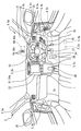
第一実施形態による走行アシストシステムを搭載したホスト車両の車室内を示す内観図である。
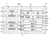
第一実施形態による走行アシストシステムを示すブロック図である。
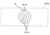
図1のHUDによる表示状態を示す正面図である。
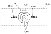
図1のHUDによる表示状態を示す正面図である。
図1のHUDによる表示状態を示す正面図である。
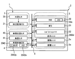
図2のHCUにより構築される複数のブロックを示すブロック図である。
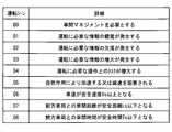
図6のシーン推定ブロックにより推定される運転シーンについて説明するための説明表である。
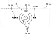
図6のリスク判定ブロックにより判定される運転リスクの要因となる運転シーンの例を説明するための説明図である。
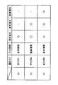
図6の情報提示制御ブロックにより例示されるアシスト情報及びその提示態様と、運転リスクとの関係を説明するための説明図である。
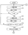
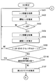
図2のHCUによるリスク判定手順の一部を示すフローチャートである。
図2のHCUによるリスク判定手順の残部を示すフローチャートである。
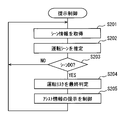
図2のHCUによる提示制御手順を示すフローチャートである。
図12のS204による最終判定について説明するための説明図である。
第二実施形態による走行アシストシステムを示すブロック図である。
第三実施形態のHCUによるリスク判定手順の一部を示すフローチャートである。
図3の変形例を示す正面図である。
図4の変形例を示す正面図である。
図5の変形例を示す正面図である。
図14の変形例を示すブロック図である。
The above and other objects, features, and advantages of the present disclosure will become more apparent from the following detailed description with reference to the accompanying drawings.
It is an interior view which shows the vehicle interior of the host vehicle carrying the driving assistance system by a first embodiment. It is a block diagram which shows the driving assistance system by 1st embodiment. It is a front view which shows the display state by HUD of FIG. It is a front view which shows the display state by HUD of FIG. It is a front view which shows the display state by HUD of FIG. FIG. 3 is a block diagram showing a plurality of blocks constructed by the HCU of FIG. 2. It is an explanatory table for demonstrating the driving scene estimated by the scene estimation block of FIG. It is explanatory drawing for demonstrating the example of the driving scene used as the factor of the driving | running risk determined by the risk determination block of FIG. It is explanatory drawing for demonstrating the relationship between the assistance information illustrated by the information presentation control block of FIG. 6, its presentation aspect, and a driving | running risk. It is a flowchart which shows a part of risk determination procedure by HCU of FIG. It is a flowchart which shows the remainder of the risk determination procedure by HCU of FIG. It is a flowchart which shows the presentation control procedure by HCU of FIG. FIG. 13 is an explanatory diagram for describing final determination in S204 of FIG. It is a block diagram which shows the driving assistance system by 2nd embodiment. It is a flowchart which shows a part of risk determination procedure by HCU of 3rd embodiment. It is a front view which shows the modification of FIG. It is a front view which shows the modification of FIG. It is a front view which shows the modification of FIG. It is a block diagram which shows the modification of FIG.
(第一実施形態)
本開示が適用される第一実施形態の走行アシストシステム1は、図1,2に示すように、車両2に搭載される。この搭載する車両2は、ホスト車両2とも、サブジェクト車両2とも言及される。また、ホスト車両2の走行する速度を車速といい、ホスト車両2の走行する道路を走行路といい、走行路上のホスト車両2に対して制限される車速を制限速度という。 (First embodiment)
Atravel assist system 1 according to a first embodiment to which the present disclosure is applied is mounted on a vehicle 2 as shown in FIGS. The vehicle 2 to be mounted is referred to as a host vehicle 2 or a subject vehicle 2. In addition, the speed at which the host vehicle 2 travels is referred to as a vehicle speed, the road on which the host vehicle 2 travels is referred to as a travel path, and the vehicle speed limited to the host vehicle 2 on the travel path is referred to as a speed limit.
本開示が適用される第一実施形態の走行アシストシステム1は、図1,2に示すように、車両2に搭載される。この搭載する車両2は、ホスト車両2とも、サブジェクト車両2とも言及される。また、ホスト車両2の走行する速度を車速といい、ホスト車両2の走行する道路を走行路といい、走行路上のホスト車両2に対して制限される車速を制限速度という。 (First embodiment)
A
図2に示すように走行アシストシステム1は、周辺監視系3、車両制御系4及び情報提示系5から構成されている。これら走行アシストシステム1の各系3,4,5は、例えばLAN(Local Area Network)等の車内ネットワーク6を介して接続されている。
As shown in FIG. 2, the travel assist system 1 includes a periphery monitoring system 3, a vehicle control system 4, and an information presentation system 5. The systems 3, 4, and 5 of the travel assist system 1 are connected via an in-vehicle network 6 such as a LAN (Local Area Network).
周辺監視系3は、外界センサ30及び周辺監視ECU(Electronic Control Unit)31を備えている。外界センサ30は、ホスト車両2の外界に存在して衝突する可能性のある障害物、例えば他車両、人工構造物、人間及び動物等や、外界に存在する交通表示を検知する。外界センサ30は、例えばソナー、レーダ及びカメラ等のうち、一種類又は複数種類である。
The periphery monitoring system 3 includes an external sensor 30 and a periphery monitoring ECU (Electronic Control Unit) 31. The outside sensor 30 detects obstacles that exist in the outside world of the host vehicle 2 and may collide, such as other vehicles, artificial structures, humans and animals, and traffic indications in the outside world. The external sensor 30 is, for example, one type or plural types of sonar, radar, camera, and the like.
具体的にソナーは、ホスト車両2のうち例えばフロント部又はリア部等に設置される超音波センサである。ソナーは、ホスト車両2の外界のうち検知エリアへと送信した超音波の反射波を受信することで、当該検知エリア内の障害物を検知して検知信号を出力する。レーダは、ホスト車両2のうち例えばフロント部若しくはリア部等に設置されるミリ波センサ、又はレーザセンサである。レーダは、ホスト車両2の外界のうち検知エリアへと送信したミリ波若しくは準ミリ波、又はレーザの反射波を受信することで、当該検知エリア内の障害物を検知して検知信号を出力する。カメラは、ホスト車両2のうち例えばルームミラー若しくはドアミラー等に設置される単眼式、又は複眼式のカメラである。カメラは、ホスト車両2の外界のうち検知エリアを撮影することで、当該検知エリア内の障害物又は交通表示を検知して画像信号を出力する。
Specifically, the sonar is an ultrasonic sensor installed in, for example, the front part or the rear part of the host vehicle 2. The sonar receives the reflected ultrasonic wave transmitted to the detection area in the external world of the host vehicle 2, thereby detecting an obstacle in the detection area and outputting a detection signal. The radar is a millimeter wave sensor or a laser sensor installed in, for example, the front part or the rear part of the host vehicle 2. The radar receives the millimeter wave or quasi-millimeter wave transmitted to the detection area in the outside world of the host vehicle 2 or the reflected wave of the laser, thereby detecting an obstacle in the detection area and outputting a detection signal. . The camera is a monocular or compound eye camera installed in, for example, a room mirror or a door mirror of the host vehicle 2. The camera captures a detection area in the outside world of the host vehicle 2 to detect an obstacle or traffic display in the detection area and outputs an image signal.
図2に示す周辺監視ECU31は、プロセッサ及びメモリを有するマイクロコンピュータを主体として構成され、外界センサ30及び車内ネットワーク6に接続されている。周辺監視ECU31は、例えば制限速度標識、止まれ標識、交差点標識、出入口案内標識、トンネル標識及び勾配標識等といった標識情報、並びに白線及び黄線等といった区画線情報を、外界センサ30の出力信号に基づき取得する。それと共に周辺監視ECU31は、例えば障害物の種類、及びホスト車両2に対する障害物の相対関係等といった障害物情報を、外界センサ30の出力信号に基づき取得する。ここで特に障害物情報としては、例えば前方障害物である前方車両とホスト車両2との間において車間距離、車間時間、相対速度及び衝突予測時間(TTC:Time To Collision)等が周辺監視ECU31により取得される。尚、車間時間とは、車間距離を車速で除して得られる時間を意味する。また、TTCとは、車間距離を相対速度で除して得られる時間を意味する。
2 is composed mainly of a microcomputer having a processor and a memory, and is connected to the external sensor 30 and the in-vehicle network 6. The surroundings monitoring ECU 31 uses, for example, sign information such as a speed limit sign, a stop sign, an intersection sign, an entrance / exit guide sign, a tunnel sign and a gradient sign, and lane marking information such as a white line and a yellow line based on an output signal of the external sensor 30. get. At the same time, the periphery monitoring ECU 31 acquires obstacle information such as the type of the obstacle and the relative relationship of the obstacle with respect to the host vehicle 2 based on the output signal of the external sensor 30. Here, as the obstacle information, for example, an inter-vehicle distance, an inter-vehicle time, a relative speed, a predicted collision time (TTC: Time To Collision) and the like between the front vehicle as the front obstacle and the host vehicle 2 are determined by the peripheral monitoring ECU 31. To be acquired. The inter-vehicle time means a time obtained by dividing the inter-vehicle distance by the vehicle speed. TTC means a time obtained by dividing the inter-vehicle distance by the relative speed.
車両制御系4は、車両状態センサ40、乗員センサ41及び車両制御ECU42を備えている。車両状態センサ40は、車内ネットワーク6に接続されている。車両状態センサ40は、ホスト車両2の走行状態を検知する。車両状態センサ40は、例えば車速センサ、回転数センサ、車輪速センサ、加速度センサ、舵角センサ、照度センサ、外気温センサ、燃料センサ、水温センサ、バッテリセンサ及び電波受信機等のうち、一種類又は複数種類である。
The vehicle control system 4 includes a vehicle state sensor 40, an occupant sensor 41, and a vehicle control ECU 42. The vehicle state sensor 40 is connected to the in-vehicle network 6. The vehicle state sensor 40 detects the traveling state of the host vehicle 2. The vehicle state sensor 40 is, for example, one of a vehicle speed sensor, a rotation speed sensor, a wheel speed sensor, an acceleration sensor, a rudder angle sensor, an illuminance sensor, an outside air temperature sensor, a fuel sensor, a water temperature sensor, a battery sensor, a radio wave receiver, and the like. Or there are multiple types.
具体的に車速センサは、ホスト車両2の車速を検知することで、当該検知に応じた車速信号を出力する。回転数センサは、ホスト車両2におけるエンジン回転数を検知することで、当該検知に応じた回転数信号を出力する。車輪速センサは、ホスト車両2における車輪の回転速度を検知することで、当該検知に応じた車輪速信号を出力する。加速度センサは、ホスト車両2に作用する加速度を検知することで、当該検知に応じた加速度信号を出力する。舵角センサは、ホスト車両2の舵角を検知することで、当該検知に応じた舵角信号を出力する。照度センサは、ホスト車両2の外界における照度を検知することで、当該検知に応じた照度信号を出力する。外気温センサは、ホスト車両2の外界における気温を検知することで、当該検知に応じた外気温信号を出力する。燃料センサは、ホスト車両2の燃料タンクにおける燃料残量を検知することで、当該検知に応じた燃料信号を出力する。水温センサは、ホスト車両2における内燃機関の冷却水温度を検知することで、当該検知に応じた水温信号を出力する。バッテリセンサは、ホスト車両2のバッテリ残量を検知することで、当該検知に応じたバッテリ信号を出力する。
Specifically, the vehicle speed sensor detects the vehicle speed of the host vehicle 2 and outputs a vehicle speed signal corresponding to the detection. The rotation speed sensor detects the engine rotation speed in the host vehicle 2 and outputs a rotation speed signal corresponding to the detection. The wheel speed sensor outputs a wheel speed signal corresponding to the detection by detecting the rotational speed of the wheel in the host vehicle 2. The acceleration sensor outputs an acceleration signal according to the detection by detecting the acceleration acting on the host vehicle 2. The steering angle sensor detects the steering angle of the host vehicle 2 and outputs a steering angle signal corresponding to the detection. The illuminance sensor outputs an illuminance signal corresponding to the detection by detecting the illuminance in the external environment of the host vehicle 2. The outside air temperature sensor detects the outside air temperature of the host vehicle 2 and outputs an outside air temperature signal corresponding to the detection. The fuel sensor detects the remaining amount of fuel in the fuel tank of the host vehicle 2 and outputs a fuel signal corresponding to the detection. The water temperature sensor detects the coolant temperature of the internal combustion engine in the host vehicle 2 and outputs a water temperature signal corresponding to the detection. The battery sensor outputs a battery signal corresponding to the detection by detecting the remaining battery level of the host vehicle 2.
電波受信機は、路車間通信用の路側機等からの出力電波を受信することで、例えばホスト車両2の現在又は将来の走行位置等での気象情報に関する気象信号を出力する。また、電波受信機は、例えば測位衛星、車車間通信用の他車両送信機、及び路車間通信用の路側機等からの出力電波を受信することで、交通信号を出力する。ここで交通信号は、例えば走行位置、走行速度、走行時刻、走行路状態及び制限速度等といったホスト車両2に関連する交通情報、並びに上記の障害物情報を表わす信号である。
The radio wave receiver receives an output radio wave from a roadside machine for road-to-vehicle communication, and outputs a weather signal related to weather information at the current or future travel position of the host vehicle 2, for example. The radio receiver outputs a traffic signal by receiving output radio waves from, for example, a positioning satellite, another vehicle transmitter for inter-vehicle communication, and a roadside unit for road-to-vehicle communication. Here, the traffic signal is a signal representing the traffic information related to the host vehicle 2 such as the travel position, travel speed, travel time, travel path state, speed limit, and the like, and the obstacle information.
乗員センサ41は、車内ネットワーク6に接続されている。乗員センサ41は、図1に示すホスト車両2の車室2c内に搭乗したユーザの状態又は操作を検知する。乗員センサ41は、例えばパワースイッチ、ユーザ状態モニタ、表示設定スイッチ、ライトスイッチ、ターンスイッチ、ワイパスイッチ、シフトスイッチ、車間マネジメントスイッチ及びクルーズ制御スイッチ等のうち、一種類又は複数種類である。
The passenger sensor 41 is connected to the in-vehicle network 6. The occupant sensor 41 detects the state or operation of a user who has boarded the passenger compartment 2c of the host vehicle 2 shown in FIG. The occupant sensor 41 is, for example, one type or a plurality of types among a power switch, a user status monitor, a display setting switch, a light switch, a turn switch, a wiper switch, a shift switch, an inter-vehicle management switch, a cruise control switch, and the like.
具体的にパワースイッチは、ホスト車両2の内燃機関又は電動モータを始動させるために車室2c内にてユーザによりオン操作されることで、当該操作に応じたパワー信号を出力する。ユーザ状態モニタは、車室2c内にて運転席20上のユーザ状態を画像センサにより撮影することで、当該ユーザ状態を検知して画像信号を出力する。表示設定スイッチは、車室2c内にて表示状態を設定するためにユーザにより操作されることで、当該操作に応じた表示設定信号を出力する。ライトスイッチは、ホスト車両2の各種ライトを点灯させるために車室2c内にてユーザによりオン操作されることで、当該操作に応じたライト信号を出力する。ターンスイッチは、ホスト車両2の方向指示器を作動させるために車室2c内にてユーザによりオン操作されることで、当該操作に応じたターン信号を出力する。ワイパスイッチは、ホスト車両2のワイパを作動させるために車室2c内にてユーザによりオン操作されることで、当該操作に応じたワイパ信号を出力する。シフトスイッチは、ホスト車両2の変速状態を変更するために車室2c内にてユーザにより操作されるシフトレバー29のシフト位置を検知することで、当該検知に応じたシフト信号を出力する。
Specifically, the power switch is turned on by the user in the passenger compartment 2c to start the internal combustion engine or the electric motor of the host vehicle 2, and outputs a power signal corresponding to the operation. The user state monitor captures the user state on the driver's seat 20 in the passenger compartment 2c with an image sensor, thereby detecting the user state and outputting an image signal. The display setting switch is operated by the user to set the display state in the passenger compartment 2c, and outputs a display setting signal corresponding to the operation. The light switch is turned on by the user in the passenger compartment 2c to turn on various lights of the host vehicle 2, and outputs a light signal corresponding to the operation. The turn switch is turned on by the user in the passenger compartment 2c to operate the direction indicator of the host vehicle 2, and outputs a turn signal corresponding to the operation. The wiper switch is turned on by the user in the passenger compartment 2c to operate the wiper of the host vehicle 2, and outputs a wiper signal corresponding to the operation. The shift switch detects the shift position of the shift lever 29 operated by the user in the passenger compartment 2c to change the shift state of the host vehicle 2, and outputs a shift signal corresponding to the detection.
車間マネジメントスイッチは、前方障害物のうち同一レーンにて同一方向へと走行する前方車両に対してホスト車両2の車間状態を車間マネジメントにより管理するために、車室2c内にてユーザによりオン操作されることで、当該操作に応じたマネジメント信号を出力する。ここで車間状態とは、前方車両に対するホスト車両2の車間距離及び車間時間を含む概念である。クルーズ制御スイッチは、そうした車間状態として車間距離又はホスト車両2の車速を自動制御するために、車室2c内にてユーザによりオン操作されることで、当該操作に応じたクルーズ信号を出力する。ここで本実施形態では、車間マネジメントスイッチとクルーズ制御スイッチとのうち一方のみを選択的にオンすることが可能となっている。即ち、車間マネジメントスイッチは、クルーズ制御スイッチがオフ操作されているときに、オン操作可能となっている。換言すると、本実施形態の車間マネジメントは、ホスト車両2の車速や車間距離の自動制御を含まず、ユーザ自らが運転している状態にて、そのユーザ自らが安全な運転を行うように促す情報を、後述する運転リスクに応じて提示するものである。そこで、以下では、クルーズ制御スイッチがオフ操作され且つ車間マネジメントスイッチがオン操作されている状態を、「車間マネジメント許容状態」という。
The inter-vehicle management switch is turned on by the user in the passenger compartment 2c in order to manage the inter-vehicle state of the host vehicle 2 with respect to the front vehicle traveling in the same direction on the same lane among the front obstacles. As a result, a management signal corresponding to the operation is output. Here, the inter-vehicle state is a concept including the inter-vehicle distance and inter-vehicle time of the host vehicle 2 with respect to the preceding vehicle. In order to automatically control the inter-vehicle distance or the vehicle speed of the host vehicle 2 as such an inter-vehicle state, the cruise control switch is turned on by the user in the passenger compartment 2c, and outputs a cruise signal corresponding to the operation. Here, in the present embodiment, only one of the inter-vehicle management switch and the cruise control switch can be selectively turned on. That is, the inter-vehicle management switch can be turned on when the cruise control switch is turned off. In other words, the inter-vehicle management of the present embodiment does not include the automatic control of the vehicle speed and the inter-vehicle distance of the host vehicle 2, and information that prompts the user to drive safely while the user is driving. Is presented according to the driving risk described later. Therefore, in the following, the state where the cruise control switch is turned off and the inter-vehicle management switch is turned on is referred to as “inter-vehicle management allowable state”.
図2に示す車両制御ECU42は、プロセッサ及びメモリを有するマイクロコンピュータを主体として構成され、車内ネットワーク6に接続されている。車両制御ECU42は、エンジン制御ECU、モータ制御ECU、ブレーキ制御ECU及び統合制御ECU等のうち、統合制御ECUを少なくとも含む一種類又は複数種類である。
The vehicle control ECU 42 shown in FIG. 2 is mainly composed of a microcomputer having a processor and a memory, and is connected to the in-vehicle network 6. The vehicle control ECU 42 is one type or a plurality of types including at least an integrated control ECU among an engine control ECU, a motor control ECU, a brake control ECU, an integrated control ECU, and the like.
具体的にエンジン制御ECUは、エンジンのスロットルアクチュエータや燃料噴射弁の作動をアクセルペダル26(図1参照)の操作に従って又は自動で制御することで、ホスト車両2の車速を加減速する。モータ制御ECUは、モータジェネレータの作動をアクセルペダル26の操作に従って又は自動で制御することで、ホスト車両2の車速を加減速する。ブレーキ制御ECUは、ブレーキアクチュエータの作動をブレーキペダル27(図1参照)の操作に従って又は自動で制御することで、ホスト車両2の車速を加減速する。
Specifically, the engine control ECU accelerates or decelerates the vehicle speed of the host vehicle 2 by controlling the operation of the throttle actuator and the fuel injection valve of the engine according to the operation of the accelerator pedal 26 (see FIG. 1) or automatically. The motor control ECU accelerates or decelerates the vehicle speed of the host vehicle 2 by controlling the operation of the motor generator according to the operation of the accelerator pedal 26 or automatically. The brake control ECU accelerates or decelerates the vehicle speed of the host vehicle 2 by controlling the operation of the brake actuator according to the operation of the brake pedal 27 (see FIG. 1) or automatically.
統合制御ECUは、例えばセンサ40,41の出力信号、周辺監視ECU31での取得情報、及び車両制御ECU42としての他制御ECUでの制御情報等に基づき、当該他制御ECUの作動を同期制御する。特に本実施形態の統合制御ECUは、車両制御ECU42としての他制御ECUに制御指令を与えることで、前方車両等の前方障害物に対するホスト車両2の衝突被害を自動で軽減又は回避するように、「緊急制御ユニット」として作動する。特に本実施形態の統合制御ECUは、緊急制御条件が成立した場合に、ホスト車両2の車速を強制的に自動減速する衝突被害軽減制動(AEB:Autonomous Emergency Braking)を、実現する。ここで、AEBの緊急制御条件としては、TTCが例えば5秒以下にまで迫ること等である。
The integrated control ECU synchronously controls the operation of the other control ECU based on, for example, the output signals of the sensors 40 and 41, the acquired information in the periphery monitoring ECU 31, the control information in the other control ECU as the vehicle control ECU 42, and the like. In particular, the integrated control ECU of the present embodiment provides a control command to the other control ECU as the vehicle control ECU 42 so as to automatically reduce or avoid the collision damage of the host vehicle 2 against the front obstacle such as the front vehicle. Operates as an “emergency control unit”. In particular, the integrated control ECU of the present embodiment realizes collision damage mitigation braking (AEB: Autonomous Emergency Braking) that automatically decelerates the vehicle speed of the host vehicle 2 when an emergency control condition is satisfied. Here, the emergency control condition for AEB is, for example, that TTC approaches 5 seconds or less.
また、本実施形態の統合制御ECUは、クルーズ制御スイッチがユーザによりオン操作された場合に、ホスト車両2の全車速域での車間距離又は車速を自動制御する全車速域アダプティブクルーズ制御(FSRA:Full Speed Range Adaptive Cruise Control)を、実現する。このとき統合制御ECUにおいては、前方車両が存在しない場合には、ホスト車両2の車速がユーザ設定の速度となるように、FSRAが機能する。また一方、前方車両が存在する場合に統合制御ECUにおいては、前方車両に対するホスト車両2の車間距離がユーザ設定の距離以上となるように、且つホスト車両2の車速がユーザ設定の速度以下となるようにFSRAが機能する。ここで、ユーザ設定の車間距離は、ホスト車両2の車速に応じて変化する。例えばホスト車両2が高速道路を通常走行している場合には、前方車両に対するホスト車両2の車間距離が60m以上(車間時間では2秒以上)、又はホスト車両2の車速が100km/h以下となるように、FSRAが機能する。
Further, the integrated control ECU of this embodiment, when the cruise control switch is turned on by the user, the full vehicle speed range adaptive cruise control (FSRA) that automatically controls the inter-vehicle distance or the vehicle speed in the full vehicle speed range of the host vehicle 2. Full Speed Range Adaptive Cruise Control) is realized. At this time, in the integrated control ECU, when there is no preceding vehicle, the FSRA functions so that the vehicle speed of the host vehicle 2 becomes the speed set by the user. On the other hand, in the case where there is a preceding vehicle, the integrated control ECU makes the inter-vehicle distance of the host vehicle 2 with respect to the preceding vehicle equal to or greater than the user-set distance and the vehicle speed of the host vehicle 2 is equal to or less than the user-set speed. FSRA functions as follows. Here, the inter-vehicle distance set by the user changes according to the vehicle speed of the host vehicle 2. For example, when the host vehicle 2 normally travels on an expressway, the distance between the host vehicle 2 and the preceding vehicle is 60 m or more (2 seconds or more in the inter-vehicle time), or the host vehicle 2 has a vehicle speed of 100 km / h or less. Thus, FSRA functions.
尚、AEBは、クルーズ制御スイッチの状態や車間マネジメントスイッチの状態に拘らず、緊急制御条件が成立した場合に実行される。即ち、緊急制御条件(例えばTTC)が条件を満たせば、FSRAや車間マネジメントが実行中であってもAEBが割り込み処理として実行され、当該AEB実行中はFSRAや車間マネジメントの機能が停止される。
Note that AEB is executed when an emergency control condition is satisfied regardless of the state of the cruise control switch or the state of the inter-vehicle management switch. That is, if the emergency control condition (for example, TTC) satisfies the condition, the AEB is executed as an interruption process even when the FSRA and the inter-vehicle management are being executed, and the functions of the FFSRA and the inter-vehicle management are stopped during the execution of the AEB.
情報提示系5は、音響ユニット5s、振動ユニット5v及び表示ユニット5dを組み合わせてなり、それらのユニット5s,5v,5dをそれぞれ「情報提示ユニット」として機能させる。
The information presentation system 5 is a combination of the acoustic unit 5s, the vibration unit 5v, and the display unit 5d, and causes these units 5s, 5v, and 5d to function as “information presentation units”, respectively.
音響ユニット5sは、情報を聴覚提示するためにホスト車両2に搭載されている。音響ユニット5sは、スピーカ及び音源回路を主体として構成され、車内ネットワーク6に接続されている。音響ユニット5sは、図1に示すホスト車両2の車室2c内にて例えば運転席20、インストルメントパネル22及びドア25のうち一箇所又は複数箇所に設置されて、運転席20上のユーザにより知覚可能な報知音波又は報知音声を発する。
The acoustic unit 5s is mounted on the host vehicle 2 in order to present information in an auditory manner. The acoustic unit 5s is mainly composed of a speaker and a sound source circuit, and is connected to the in-vehicle network 6. The acoustic unit 5s is installed, for example, in one or a plurality of locations of the driver seat 20, the instrument panel 22, and the door 25 in the passenger compartment 2c of the host vehicle 2 shown in FIG. A perceptible sound wave or sound is generated.
図2に示す振動ユニット5vは、情報を触覚提示するためにホスト車両2に搭載されている。振動ユニット5vは、振動アクチュエータを主体として構成され、車内ネットワーク6に接続されている。振動ユニット5vは、図1に示す車室2c内にて例えば運転席20、ステアリングハンドル24、アクセルペダル26、ブレーキペダル27及びフットレスト28のうち一箇所又は複数箇所に設置されて、運転席20上のユーザにより知覚可能な報知振動を発する。
The vibration unit 5v shown in FIG. 2 is mounted on the host vehicle 2 for tactile presentation of information. The vibration unit 5v is mainly composed of a vibration actuator, and is connected to the in-vehicle network 6. The vibration unit 5v is installed, for example, in one or a plurality of locations of the driver's seat 20, the steering handle 24, the accelerator pedal 26, the brake pedal 27, and the footrest 28 in the passenger compartment 2c shown in FIG. An alarm vibration that can be perceived by the user is generated.
図2に示す表示ユニット5dは、情報を視覚提示するためにホスト車両2に搭載されている。表示ユニット5dは、HUD(Head-up Display)50、MFD(Multi-Function Display)51、コンビネーションメータ52及びHCU(HMI(Human Machine Interface) Control Unit)54を備えている。
The display unit 5d shown in FIG. 2 is mounted on the host vehicle 2 for visually presenting information. The display unit 5 d includes an HUD (Head-up Display) 50, an MFD (Multi-Function Display) 51, a combination meter 52, and an HCU (HMI (Human Machine Interface) Control Unit) 54.
HUD50は、図1に示す車室2c内にてインストルメントパネル22に設置されている。HUD50は、液晶パネル又は投射スクリーンにて所定情報を示すように形成した画像56をホスト車両2のウインドシールド21に投影することで、当該画像56の虚像を運転席20上のユーザにより視認可能に表示する。このとき、HUD50による虚像表示は、ウインドシールド21への画像56の投影範囲となる所定面積の表示範囲50aにて、ホスト車両2の前方の外界風景と重なってユーザに視認される。こうしたHUD50による虚像表示としては、図2,3~5に示すような注意画像56c及び報知画像56iの表示が採用される。また、HUD50による虚像表示としては、画像56c,56iに追加して、例えばナビゲーション情報、標識情報及び障害物情報等のうち、一種類又は複数種類の情報を示す画像表示を採用してもよい。尚、インストルメントパネル22に配置されてウインドシールド21と共同して外界風景を透過させるコンバイナを用いることで、当該コンバイナに画像56を投影することによっても、虚像表示の実現が可能である。また、上記のナビゲーション情報は、例えば後に詳述するHCU54において、メモリ54mに記憶の地図情報と、センサ40の出力信号とに基づき取得可能である。
The HUD 50 is installed on the instrument panel 22 in the passenger compartment 2c shown in FIG. The HUD 50 projects the image 56 formed so as to show predetermined information on the liquid crystal panel or the projection screen onto the windshield 21 of the host vehicle 2 so that the virtual image of the image 56 can be visually recognized by the user on the driver's seat 20. indicate. At this time, the virtual image display by the HUD 50 is visually recognized by the user in a display range 50 a having a predetermined area that is a projection range of the image 56 onto the windshield 21, overlapping with an external scene in front of the host vehicle 2. As the virtual image display by the HUD 50, the display of the attention image 56c and the notification image 56i as shown in FIGS. Further, as the virtual image display by the HUD 50, in addition to the images 56c and 56i, for example, an image display indicating one type or a plurality of types of information among navigation information, sign information, obstacle information, and the like may be adopted. Note that by using a combiner that is arranged on the instrument panel 22 and transmits the outside scenery in cooperation with the windshield 21, a virtual image display can also be realized by projecting the image 56 on the combiner. The navigation information can be acquired based on the map information stored in the memory 54m and the output signal of the sensor 40, for example, in the HCU 54 described in detail later.
MFD51は、図1に示す車室2c内にてセンターコンソール23に設置される。MFD51は、一つ又は複数の液晶パネルにて所定情報を示すように形成した画像56の実像を、運転席20上のユーザにより視認可能に表示する。このとき、MFD51による実像表示は、HUD50の表示範囲50aよりも大きな面積の表示範囲51aにて、ユーザに視認される。こうしたMFD51による実像表示としては、ナビゲーション情報、オーディオ情報、映像情報及び通信情報等のうち、一種類又は複数種類の情報を示す画像表示が採用される。
The MFD 51 is installed in the center console 23 in the passenger compartment 2c shown in FIG. The MFD 51 displays a real image of the image 56 formed so as to show predetermined information on one or a plurality of liquid crystal panels so that the user on the driver's seat 20 can visually recognize the image. At this time, the real image display by the MFD 51 is visually recognized by the user in the display range 51 a having a larger area than the display range 50 a of the HUD 50. As the real image display by the MFD 51, an image display indicating one type or a plurality of types of information among navigation information, audio information, video information, communication information, and the like is employed.
コンビネーションメータ52は、車室2c内にてインストルメントパネル22に設置される。コンビネーションメータ52は、ホスト車両2に関する車両情報を、運転席20上のユーザにより視認可能に表示する。コンビネーションメータ52は、液晶パネルに形成した画像により車両情報を表示するデジタルメータ、又は指針により目盛を指示して車両情報を表示するアナログメータである。こうしたコンビネーションメータ52による表示としては、例えば車速、エンジン回転数、燃料残量、冷却水温度、バッテリ残量、並びにライトスイッチ、ターンスイッチ、シフトスイッチ、車間マネジメントスイッチ及びクルーズ制御スイッチの操作状態等のうち、一種類又は複数種類の情報を示す表示が採用される。
The combination meter 52 is installed on the instrument panel 22 in the passenger compartment 2c. The combination meter 52 displays vehicle information related to the host vehicle 2 so that the user on the driver's seat 20 can visually recognize the vehicle information. The combination meter 52 is a digital meter that displays vehicle information by an image formed on a liquid crystal panel, or an analog meter that displays vehicle information by indicating a scale with a pointer. Such display by the combination meter 52 includes, for example, vehicle speed, engine speed, fuel remaining amount, cooling water temperature, battery remaining amount, operation state of light switch, turn switch, shift switch, inter-vehicle management switch and cruise control switch, etc. Of these, a display indicating one type or a plurality of types of information is employed.
図2に示すようにHCU54は、電子制御ユニットとも言及され、本実施形態では、一例として、プロセッサ54p及びメモリ54mを有するマイクロコンピュータを主体として構成され、表示ユニット5dの表示要素50,51,52及び車内ネットワーク6に接続されている。HCU54は、音響ユニット5s及び振動ユニット5vの作動、並びに表示ユニット5dの表示要素50,51,52の作動とを同期制御する。このときHCU54は、例えばセンサ40,41の出力信号、ECU31での取得情報、ECU42での制御情報、メモリ54mの記憶情報、並びにHCU54自身の計時情報を含む取得情報等に基づき、それらの作動制御を実行する。ここで特に本実施形態では、車間マネジメントを実現するために、HCU54が「車間マネジメント装置」(あるいは「車間制御装置」とも言及される)として機能することから、以下にその詳細を説明する。尚、プロセッサ54pで実現される機能は、複数のプロセッサで実現されても良い。
As shown in FIG. 2, the HCU 54 is also referred to as an electronic control unit. In the present embodiment, the HCU 54 is configured mainly by a microcomputer having a processor 54p and a memory 54m as an example, and the display elements 50, 51, 52 of the display unit 5d. And in-vehicle network 6. The HCU 54 controls the operations of the acoustic unit 5s and the vibration unit 5v and the operations of the display elements 50, 51, and 52 of the display unit 5d in synchronization. At this time, the HCU 54 controls the operation thereof based on, for example, output signals of the sensors 40 and 41, acquisition information in the ECU 31, control information in the ECU 42, storage information in the memory 54m, and acquisition information including time information of the HCU 54 itself. Execute. Here, particularly in the present embodiment, since the HCU 54 functions as a “vehicle distance management device” (or also referred to as “vehicle distance control device”) in order to realize vehicle distance management, details thereof will be described below. Note that the functions realized by the processor 54p may be realized by a plurality of processors.
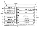
HCU54は、車間マネジメントプログラムをプロセッサ54pにより実行することで、図6に示すように複数のブロック541,542,543,544を機能的に構築する。これらのブロックは、部、デバイス、モジュール、ユニット、とも言及される。尚、これらブロック541,542,543,544のうち少なくとも一部を、一つ又は複数のIC等によりハードウェア的に構築しても勿論よい。
The HCU 54 functionally constructs a plurality of blocks 541, 542, 543, and 544 as shown in FIG. 6 by executing the inter-vehicle management program by the processor 54p. These blocks are also referred to as parts, devices, modules, units. Of course, at least a part of these blocks 541, 542, 543, and 544 may be constructed in hardware by one or a plurality of ICs.
「シーン推定部」としてのシーン推定ブロック541は、情報取得ブロック542により取得されるシーン情報に基づき、ユーザによるホスト車両2の運転シーンを推定する。このとき、シーン推定ブロック541により推定される運転シーンは、図7に示すように、シーンD0,D1,D2,D3,D4,D5,D6,D7,D8を少なくとも含んでいる。
The scene estimation block 541 as the “scene estimation unit” estimates the driving scene of the host vehicle 2 by the user based on the scene information acquired by the information acquisition block 542. At this time, the driving scene estimated by the scene estimation block 541 includes at least scenes D0, D1, D2, D3, D4, D5, D6, D7, and D8, as shown in FIG.
シーンD0とは、車間マネジメントを必要とする運転シーンである。具体的にシーンD0は、特に本実施形態では、統合制御ECUによるAEB作動前の車間マネジメント許容状態下、前方車両の後方にてホスト車両2が同一レーンにて同一方向へと走行する追従走行状態になっている状況である。ここで、シーンD0を構成する追従走行状態とは、車速が閾値V0以上且つ車間距離が閾値L0未満である状態(図10,12参照)である。こうしたシーンD0の想定に必要なシーン情報としては、車速、障害物情報としての車間距離、AEBの作動状態、クルーズ制御スイッチの操作状態(即ち、FSRAの作動状態)、及び車間マネジメントスイッチの操作状態が採用される。尚、上記の閾値V0は、ユーザによるホスト車両2の運転リスクが低下する徐行時の車速と区別するための境界値として、例えば10km/h等の値に設定される。また、上記の閾値L0は、前方車両に対するホスト車両2の運転リスクが低下する単独走行状態と区別するための境界値として、例えば100m等の値に設定される。
Scene D0 is a driving scene that requires inter-vehicle management. Specifically, in the present embodiment, the scene D0 is a follow-up traveling state in which the host vehicle 2 travels in the same direction on the same lane behind the front vehicle under the inter-vehicle management permission state before the AEB operation by the integrated control ECU. This is the situation. Here, the following traveling state constituting the scene D0 is a state where the vehicle speed is equal to or higher than the threshold value V0 and the inter-vehicle distance is less than the threshold value L0 (see FIGS. 10 and 12). The scene information necessary for the assumption of the scene D0 includes the vehicle speed, the inter-vehicle distance as obstacle information, the AEB operating state, the cruise control switch operating state (ie, the FSRA operating state), and the inter-vehicle management switch operating state. Is adopted. In addition, said threshold value V0 is set to values, such as 10 km / h, as a boundary value for distinguishing from the vehicle speed at the time of slowing at which the driving risk of the host vehicle 2 by a user falls. Moreover, said threshold value L0 is set to values, such as 100m, as a boundary value for distinguishing from the independent driving | running | working state in which the driving risk of the host vehicle 2 with respect to a preceding vehicle falls.
シーンD1とは、ホスト車両2の運転に必要な情報の錯覚が発生することで、運転リスクに対するユーザ判断又はユーザ感覚に誤りを招くおそれの想定される運転シーンである。こうしたシーンD1は、ユーザの体感速度が車速からずれ易い状況、例えば走行路が高速道路から一般道路へ切替わる状況、走行路がトンネル内となっている状況、及び走行路がサグ部となっている状況等である。こうしたシーンD1の想定に必要なシーン情報としては、例えば標識情報、交通情報、ナビゲーション情報、車速、加速度、エンジン回転数、照度、ユーザ状態、及びターンスイッチ及びライトスイッチの操作状態等のうち、一種類又は複数種類が採用される。尚、上記の高速道路とは、管轄当局により法的に規定された制限速度の最高値である法定最高速度が一般道路よりも高い走行路を、意味する。また、上記のトンネルとは、例えば山又は地下等を掘り貫いて形成された走行路を意味し、当該走行路として擬制可能なものも含む。さらにまた、上記のサグ部とは、走行路の勾配が下り方向から上り方向へ次第に変化する区間を、意味する。
Scene D1 is a driving scene in which an illusion of information necessary for driving the host vehicle 2 is generated, which may cause an error in user judgment or user feeling regarding driving risk. Such a scene D1 is a situation where the user's perceived speed is likely to deviate from the vehicle speed, for example, a situation where the travel path is switched from a highway to a general road, a situation where the travel path is in a tunnel, and a travel path is a sag section. Situation. Examples of the scene information necessary for the assumption of the scene D1 include one of sign information, traffic information, navigation information, vehicle speed, acceleration, engine speed, illuminance, user state, and operation state of the turn switch and the light switch. Types or multiple types are adopted. The expressway mentioned above means a traveling road having a legal maximum speed, which is the maximum value of the speed limit legally defined by the competent authority, higher than that of a general road. Moreover, said tunnel means the traveling path formed, for example, digging a mountain or the underground etc., and the thing which can be imitated as the said traveling path is also included. Still further, the sag portion means a section where the gradient of the travel path gradually changes from the down direction to the up direction.
シーンD2とは、ホスト車両2の運転に必要な情報の欠落が発生することで、運転リスクに対するユーザ判断に遅れを招くおそれの想定される運転シーンである。具体的にシーンD2は、ユーザに対する死角が形成されている状況、例えば走行路が上り坂の頂上部となっている状況、走行路のカーブ又は交差によりユーザの前方に構造物が存在している状況、及び走行路上の前方に駐車車両又は大型車両が存在している状況等である。シーンD2はまた、例えば雨、雪、霧、逆光、幻惑光又は夜間走行等の要因によりユーザの視程が低下している状況である。こうしたシーンD2の想定に必要なシーン情報としては、例えば標識情報、区画線情報、障害物情報、交通情報、ナビゲーション情報、車速、加速度、エンジン回転数、気象情報、計時情報、照度、外気温、舵角、並びにワイパスイッチ及びライトスイッチの操作状態等のうち、一種類又は複数種類が採用される。尚、上記の頂上部とは、走行路の勾配が上り方向から下り方向へ次第に変化する区間を意味する。
Scene D2 is a driving scene that is expected to cause a delay in user judgment regarding driving risk due to a lack of information necessary for driving the host vehicle 2. Specifically, in the scene D2, there is a structure in front of the user due to a situation where a blind spot is formed with respect to the user, for example, a situation where the traveling road is the top of an uphill, a curve or intersection of the traveling road. This is the situation and the situation where a parked vehicle or a large vehicle exists in front of the road. The scene D2 is also a situation in which the user's visibility is reduced due to factors such as rain, snow, fog, backlight, dazzling light, or night driving. As scene information necessary for the assumption of such a scene D2, for example, sign information, lane marking information, obstacle information, traffic information, navigation information, vehicle speed, acceleration, engine speed, weather information, time information, illuminance, outside temperature, Of the steering angle and the operation state of the wiper switch and the light switch, one type or a plurality of types are adopted. In addition, said top part means the area where the gradient of a traveling path changes gradually from an up direction to a down direction.
シーンD3とは、ホスト車両2の運転に必要な情報の増大が発生することで、運転リスクに対するユーザ判断に誤りを招くおそれの想定される運転シーンである。具体的にシーンD3は、例えば交差点への進入等により多方向の安全確認が必要な状況等である。こうしたシーンD3の想定に必要なシーン情報としては、例えば標識情報、交通情報及びナビゲーション情報等のうち、一種類又は複数種類が採用される。
Scene D3 is a driving scene that is assumed to cause an error in user judgment regarding driving risk due to an increase in information necessary for driving the host vehicle 2. Specifically, the scene D3 is a situation in which multi-directional safety confirmation is required, for example, by entering an intersection. As the scene information necessary for the assumption of such a scene D3, for example, one type or a plurality of types are adopted among sign information, traffic information, navigation information, and the like.
シーンD4とは、ホスト車両2の運転に必要な操作上のタスクが増大することで、運転リスクに対するユーザ判断に誤りを招くおそれの想定される運転シーンである。具体的にシーンD4は、例えば右折、左折、又は走行路の曲がり等によりホスト車両2の進行方向が変化する状況である。こうしたシーンD4の想定に必要なシーン情報としては、例えば標識情報、区画線情報、交通情報、ナビゲーション情報、ユーザ状態、車速、舵角、及びターンスイッチの操作状態等のうち、一種類又は複数種類が採用される。
Scene D4 is a driving scene that is likely to cause an error in user judgment on driving risk due to an increase in operational tasks necessary for driving the host vehicle 2. Specifically, the scene D4 is a situation in which the traveling direction of the host vehicle 2 changes due to, for example, a right turn, a left turn, or a turn of the traveling road. As scene information necessary for the assumption of such a scene D4, for example, one type or a plurality of types among sign information, lane marking information, traffic information, navigation information, user status, vehicle speed, steering angle, and turn switch operation status, etc. Is adopted.
シーンD5とは、ホスト車両2が自然作用により加速する又は減速を阻害されることで、運転リスクが上昇し易い運転シーンである。具体的にシーンD5は、例えば走行路が下り坂となること等によりホスト車両2が加速する状況である。シーンD5はまた、ホスト車両2の減速が阻害される状況、例えばアイスバーン、未舗装、雪又は雨等の要因により走行路が低μ路となっている状況である。こうしたシーンD5の想定に必要なシーン情報としては、例えば標識情報、交通情報、ナビゲーション情報、車速、加速度、エンジン回転数、気象情報、外気温、車輪回転速度、及びワイパスイッチの操作状態等のうち、一種類又は複数種類が採用される。尚、上記の低μ路とは、ホスト車両2の車輪に対して路面のすべり摩擦係数が低いことで、当該車輪のスリップ率が増大する走行路を意味する。
Scene D5 is a driving scene in which the driving risk is likely to increase due to the host vehicle 2 being accelerated or obstructed by natural action. Specifically, the scene D5 is a situation in which the host vehicle 2 accelerates due to, for example, a downhill road. The scene D5 is also a situation where deceleration of the host vehicle 2 is hindered, for example, a situation where the traveling road is a low μ road due to factors such as ice burn, unpaved, snow or rain. The scene information necessary for the assumption of the scene D5 includes, for example, sign information, traffic information, navigation information, vehicle speed, acceleration, engine speed, weather information, outside air temperature, wheel rotational speed, and wiper switch operation state. One type or a plurality of types are adopted. Note that the low μ road means a traveling road where the slip coefficient of the road surface is increased due to a low sliding friction coefficient of the road surface with respect to the wheel of the host vehicle 2.
シーンD6とは、ホスト車両2の車速が安全速度Vs以上となることで、運転リスクが上昇する運転シーンである。ここで安全速度Vsとは、運転リスク上においてホスト車両2の安全を確保するのに必要な車速であり、例えば法定最高速を含む制限速度、又は当該制限速度を走行路のすべり摩擦係数、気象情報若しくはユーザ状態を考慮して補正した速度等に、設定される。こうした安全速度Vsに基づいてシーンD6を想定するのに必要なシーン情報としては、例えば障害物情報、区画線情報、標識情報、交通情報、ナビゲーション情報、車速、エンジン回転数、気象情報、外気温、車輪回転速度、並びにペダル26,27及びワイパスイッチの操作状態等のうち、一種類又は複数種類が採用される。
Scene D6 is a driving scene in which driving risk increases when the vehicle speed of the host vehicle 2 is equal to or higher than the safe speed Vs. Here, the safe speed Vs is a vehicle speed necessary for ensuring the safety of the host vehicle 2 in terms of driving risk. For example, the speed limit including the legal maximum speed, or the speed limit is calculated based on the sliding friction coefficient of the road, weather, and the like. It is set to a speed corrected in consideration of information or a user state. Examples of scene information necessary to assume the scene D6 based on the safe speed Vs include obstacle information, lane marking information, sign information, traffic information, navigation information, vehicle speed, engine speed, weather information, and outside temperature. One type or a plurality of types are adopted among the wheel rotation speed and the operation states of the pedals 26 and 27 and the wiper switch.
シーンD7とは、ホスト車両2と前方車両との車間距離が運転リスク上の安全距離Ls以下となることで、運転リスクが上昇する運転シーンである。ここで安全距離Lsとは、運転リスク上においてホスト車両2の安全を確保するのに必要な車間距離であり、例えば車速に応じた最短制動距離、又は当該最短制動距離を走行路のすべり摩擦係数、気象情報若しくはユーザ状態を考慮して補正した距離等に、設定される。こうした安全距離Lsに基づいてシーンD7を想定するのに必要なシーン情報としては、例えば障害物情報、区画線情報、標識情報、交通情報、ナビゲーション情報、車速、エンジン回転数、気象情報、外気温、車輪回転速度、並びにペダル26,27及びワイパスイッチの操作状態等のうち、一種類又は複数種類が採用される。
Scene D7 is a driving scene in which driving risk increases when the inter-vehicle distance between the host vehicle 2 and the preceding vehicle is equal to or less than the safe distance Ls on driving risk. Here, the safety distance Ls is an inter-vehicle distance necessary for ensuring the safety of the host vehicle 2 in terms of driving risk. For example, the shortest braking distance according to the vehicle speed, or the shortest braking distance is the sliding friction coefficient of the traveling road. The distance is corrected in consideration of weather information or user status. Examples of scene information necessary to assume the scene D7 based on the safety distance Ls include obstacle information, lane marking information, sign information, traffic information, navigation information, vehicle speed, engine speed, weather information, and outside temperature. One type or a plurality of types are adopted among the wheel rotation speed and the operation states of the pedals 26 and 27 and the wiper switch.
シーンD8とは、ホスト車両2と前方車両との車間時間が運転リスク上の安全時間Ts以下となることで、運転リスクが上昇する運転シーンである。ここで安全時間Tsとは、運転リスク上においてホスト車両2の安全を確保するのに必要な車間時間であり、走行路のすべり摩擦係数、気象情報又はユーザ状態を考慮して、例えば2~3秒等の値に設定される。こうした安全時間Tsに基づいてシーンD8を想定するのに必要なシーン情報としては、例えば障害物情報、区画線情報、標識情報、交通情報、ナビゲーション情報、車速、エンジン回転数、計時情報、気象情報、外気温、車輪回転速度、並びにペダル26,27及びワイパスイッチの操作状態等のうち、一種類又は複数種類が採用される。
Scene D8 is a driving scene in which the driving risk increases when the inter-vehicle time between the host vehicle 2 and the preceding vehicle is equal to or less than the safety time Ts in terms of driving risk. Here, the safety time Ts is an inter-vehicle time necessary for ensuring the safety of the host vehicle 2 in terms of driving risk. For example, 2 to 3 in consideration of the sliding friction coefficient of the travel road, weather information, or the user condition. Set to a value such as seconds. Examples of scene information necessary to assume the scene D8 based on the safety time Ts include obstacle information, lane marking information, sign information, traffic information, navigation information, vehicle speed, engine speed, time information, and weather information. One type or a plurality of types are adopted among the outside air temperature, the wheel rotation speed, and the operation states of the pedals 26 and 27 and the wiper switch.
「シーン情報取得部」として図6に示す情報取得ブロック542は、ホスト車両2の運転シーンに関連するシーン情報として、シーン推定ブロック541による運転シーンの推定に必要な情報を取得する。このとき情報取得ブロック542は、センサ40,41の出力信号、車両制御ECU42での制御情報、並びに周辺監視ECU31及びHCU54での取得情報に基づくことで、情報取得を実現する。
An information acquisition block 542 shown in FIG. 6 as a “scene information acquisition unit” acquires information necessary for estimation of a driving scene by the scene estimation block 541 as scene information related to the driving scene of the host vehicle 2. At this time, the information acquisition block 542 realizes information acquisition based on the output signals of the sensors 40 and 41, the control information in the vehicle control ECU 42, and the acquisition information in the periphery monitoring ECU 31 and the HCU 54.
具体的に、シーンD0の想定に必要な情報取得は、周辺監視ECU31での取得情報、統合制御ECUでの制御情報、並びに車速センサ、クルーズ制御スイッチ及び車間マネジメントスイッチの出力信号に基づく。
Specifically, the information acquisition necessary for the assumption of the scene D0 is based on the acquisition information in the peripheral monitoring ECU 31, the control information in the integrated control ECU, and the output signals of the vehicle speed sensor, the cruise control switch, and the inter-vehicle management switch.
シーンD1の想定に必要な情報取得は、例えば周辺監視ECU31及びHCU54(以下、これらを総称する場合は制御要素31,54という)での取得情報、並びに電波受信機、車速センサ、加速度センサ、回転数センサ、照度センサ、ユーザ状態モニタ、ターンスイッチ及びライトスイッチの出力信号等のうち、一種類又は複数種類に基づく。シーンD2の想定に必要な情報取得は、例えば制御要素31,54での取得情報、並びに電波受信機、車速センサ、加速度センサ、回転数センサ、照度センサ、外気温センサ、舵角センサ、ワイパスイッチ及びライトスイッチの出力信号等のうち、一種類又は複数種類に基づく。シーンD3の想定に必要な情報取得は、例えば制御要素31,54での取得情報、及び電波受信機の出力信号等のうち、一種類又は複数種類に基づく。
Information acquisition necessary for the assumption of the scene D1 includes, for example, acquisition information in the peripheral monitoring ECU 31 and the HCU 54 (hereinafter, collectively referred to as control elements 31, 54), a radio wave receiver, a vehicle speed sensor, an acceleration sensor, a rotation Based on one or a plurality of types of output signals from a number sensor, illuminance sensor, user status monitor, turn switch, and light switch. Information necessary for the assumption of the scene D2 includes, for example, information acquired by the control elements 31 and 54, a radio wave receiver, a vehicle speed sensor, an acceleration sensor, a rotation speed sensor, an illuminance sensor, an outside air temperature sensor, a steering angle sensor, and a wiper switch. And based on one or more types of output signals of the light switch. Information acquisition necessary for the assumption of the scene D3 is based on one type or a plurality of types of information acquired by the control elements 31 and 54, an output signal of the radio receiver, and the like.
シーンD4の想定に必要な情報取得は、例えば制御要素31,54での取得情報、並びに電波受信機、ユーザ状態モニタ、車速センサ、舵角センサ及びターンスイッチの出力信号等のうち、一種類又は複数種類に基づく。シーンD5の想定に必要な情報取得は、例えば制御要素31,54での取得情報、並びに電波受信機、車速センサ、加速度センサ、回転数センサ、外気温センサ、車輪速センサ及びワイパスイッチの出力信号等のうち、一種類又は複数種類に基づく。
Information acquisition necessary for the assumption of the scene D4 is, for example, one of the acquisition information in the control elements 31 and 54, and the radio receiver, the user state monitor, the vehicle speed sensor, the steering angle sensor, the output signal of the turn switch, and the like. Based on multiple types. Information acquisition necessary for the assumption of the scene D5 includes, for example, acquisition information in the control elements 31 and 54, and output signals of radio wave receivers, vehicle speed sensors, acceleration sensors, rotation speed sensors, outside air temperature sensors, wheel speed sensors, and wiper switches. Etc., based on one or more types.
シーンD6の想定に必要な情報取得は、例えば制御要素31,54での取得情報、エンジン制御ECU、モータ制御ECU及びブレーキ制御ECUの制御情報、並びに電波受信機、車速センサ、回転数センサ、外気温センサ、車輪速センサ及びワイパスイッチの出力信号等のうち、一種類又は複数種類に基づく。シーンD7の想定に必要な情報取得の場合と、シーンD8の想定に必要な情報取得の場合とについては、シーンD6の想定に必要な情報取得の場合と同様である。
Information acquisition necessary for the assumption of the scene D6 includes, for example, acquisition information in the control elements 31 and 54, control information of the engine control ECU, motor control ECU, and brake control ECU, a radio wave receiver, a vehicle speed sensor, a rotation speed sensor, Based on one type or a plurality of types of output signals from the air temperature sensor, the wheel speed sensor, the wiper switch, and the like. The information acquisition necessary for the assumption of the scene D7 and the information acquisition necessary for the assumption of the scene D8 are the same as the information acquisition necessary for the assumption of the scene D6.
こうしたシーン情報の取得に加えて、「行動情報取得部」としても機能する情報取得ブロック542は、ユーザによるホスト車両2の運転行動に関連する行動情報を、センサ40,41の出力信号及び車両制御ECU42での制御情報に基づき取得する。ここで特に本実施形態では、運転行動のうちホスト車両2の安全を確保する減速行動に関連した行動情報として、ペダル26,27及びシフトレバー29の操作状態が注目される。そこで、これら行動情報の取得は、エンジン制御ECU又はモータ制御ECUでの制御情報、ブレーキ制御ECUでの制御情報、並びに車速センサ及びシフトスイッチの出力信号等のうち、一種類又は複数種類に基づくことになる。
In addition to the acquisition of such scene information, the information acquisition block 542 that also functions as the “behavior information acquisition unit” displays the behavior information related to the driving behavior of the host vehicle 2 by the user, the output signals of the sensors 40 and 41, and the vehicle control. Obtained based on control information in the ECU 42. Here, particularly in the present embodiment, attention is paid to the operation states of the pedals 26 and 27 and the shift lever 29 as the action information related to the deceleration action that ensures the safety of the host vehicle 2 among the driving actions. Therefore, the acquisition of such behavior information is based on one or more types of control information in the engine control ECU or motor control ECU, control information in the brake control ECU, and output signals from the vehicle speed sensor and the shift switch. become.
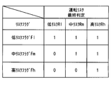
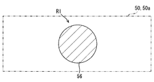
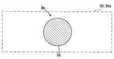
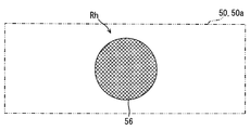
「リスク判定部」としてのリスク判定ブロック543は、シーン推定ブロック541により推定された運転シーンと、情報取得ブロック542により取得された行動情報とに基づき、運転リスクを判定する。ここで運転リスクとして本実施形態では、図8に示すように、低リスクRl、中リスクRm及び高リスクRhの三段階が採用されている。そこで、リスク判定ブロック543は、それら低リスクRl、中リスクRm及び高リスクRhの判定を下すために、複数のサブブロック545,546,547,548から構成されている。
The risk determination block 543 as the “risk determination unit” determines the driving risk based on the driving scene estimated by the scene estimation block 541 and the action information acquired by the information acquisition block 542. In this embodiment, as shown in FIG. 8, three stages of low risk Rl, medium risk Rm, and high risk Rh are employed as driving risks. Therefore, the risk determination block 543 includes a plurality of sub-blocks 545, 546, 547, and 548 in order to make a determination of the low risk Rl, the medium risk Rm, and the high risk Rh.
具体的に、図6に示す低判定サブブロック545は、シーンD1,D2,D3,D4,D5のうちいずれか一つがシーン推定ブロック541により推定された場合に、運転リスクは低リスクRlであるとの判定を下す。例えば、図8の(a)に例示するように走行路が下り坂であるシーンD5を要因C1とした運転リスクは、低リスクRlとなる。また、図8の(b)に例示するように大型車両が前方車両として存在するシーンD2を要因C1とした運転リスクも、低リスクRlとなる。
Specifically, in the low determination sub-block 545 shown in FIG. 6, when any one of the scenes D1, D2, D3, D4, and D5 is estimated by the scene estimation block 541, the driving risk is the low risk Rl. Judgment is made. For example, as illustrated in FIG. 8A, the driving risk with the factor C1 as the scene D5 in which the traveling path is a downhill is a low risk Rl. Further, as illustrated in FIG. 8B, the driving risk with the factor C1 as the scene D2 in which the large vehicle exists as the front vehicle is also a low risk Rl.
図6に示す中判定サブブロック546は、シーンD6,D7,D8のうち少なくとも一つがシーン推定ブロック541により推定された場合に、運転リスクは中リスクRmであるとの判定を下す。例えば、図8の(c)に例示するように走行路が下り坂であるシーンD5を要因C1とし、且つ車間距離が安全距離Ls以下であるシーンD7を要因C2とした運転リスクは、中リスクRmとなる。また、図8の(d)に例示するように大型車両が前方車両として存在するシーンD2を要因C1とし、且つ車間距離が安全距離Ls以下であるシーンD7を要因C2とした運転リスクも、中リスクRmとなる。
6 determines that the driving risk is the medium risk Rm when at least one of the scenes D6, D7, and D8 is estimated by the scene estimation block 541. The middle determination subblock 546 illustrated in FIG. For example, as illustrated in FIG. 8C, a driving risk with a scene D5 having a downhill traveling path as a factor C1 and a scene D7 having an inter-vehicle distance equal to or less than the safety distance Ls as a factor C2 is a medium risk. Rm. In addition, as illustrated in FIG. 8D, the driving risk with a scene D2 in which a large vehicle exists as a forward vehicle as a factor C1 and a scene D7 in which the inter-vehicle distance is equal to or less than the safety distance Ls is also a factor C2, Risk Rm.
図6に示す高判定サブブロック547は、まず、情報取得ブロック542により取得された行動情報に基づき、リスクRl,Rmに対する運転行動を推定する。さらに高判定サブブロック547は、推定された運転行動が運転リスクを低下させない場合に、運転リスクは中リスクRmよりも高い高リスクRhであるとの判定を下す。例えば、図8の(e)に例示するように、図8の(c)と同じ要因C1,C2に加えて、加速行動又は等速行動を要因C3とした運転リスクは、高リスクRhとなる。また、図8の(f)に例示するように、図8の(d)と同じ要因C1,C2に加えて、加速行動又は等速行動を要因C3とした運転リスクも、高リスクRhとなる。
The high determination sub-block 547 shown in FIG. 6 first estimates the driving behavior for the risks Rl and Rm based on the behavior information acquired by the information acquisition block 542. Further, the high determination sub-block 547 determines that the driving risk is a high risk Rh higher than the medium risk Rm when the estimated driving behavior does not reduce the driving risk. For example, as illustrated in FIG. 8E, in addition to the same factors C1 and C2 as in FIG. 8C, the driving risk with acceleration behavior or constant velocity behavior as the factor C3 is a high risk Rh. . Further, as illustrated in FIG. 8F, in addition to the same factors C1 and C2 as in FIG. 8D, the driving risk with acceleration behavior or constant velocity behavior as the factor C3 is also a high risk Rh. .
図6に示す最終判定サブブロック548は、他のサブブロック545,546,547の判定結果に基づき運転リスクの最終判定を下す。このとき、低判定サブブロック545による低リスクRlの判定は下されているが、中判定サブブロック546による中リスクRmの判定及び高判定サブブロック547による高リスクRhの判定が下されていない場合には、最終判定結果を低リスクRlに決定する。また、低判定サブブロック545による低リスクRlの判定及び中判定サブブロック546による中リスクRmの判定は下されているが、高判定サブブロック547による高リスクRhの判定が下されていない場合には、最終判定結果を中リスクRmに決定する。さらにまた、低判定サブブロック545による低リスクRlの判定及び中判定サブブロック546による中リスクRmの判定に加えて、高判定サブブロック547による高リスクRhの判定も下されている場合には、最終判定結果を高リスクRhに決定する。
The final determination sub-block 548 shown in FIG. 6 makes a final determination of the driving risk based on the determination results of the other sub-blocks 545, 546 and 547. At this time, when the low risk Rl is determined by the low determination sub-block 545, the determination of the medium risk Rm by the medium determination sub-block 546 and the determination of the high risk Rh by the high determination sub-block 547 are not performed In this case, the final determination result is determined to be low risk Rl. In addition, when the low risk Rl is determined by the low determination sub-block 545 and the medium risk Rm is determined by the medium determination sub-block 546, the high risk Rh is not determined by the high determination sub-block 547. Determines the final determination result to the medium risk Rm. Furthermore, in addition to the determination of the low risk Rl by the low determination sub-block 545 and the determination of the medium risk Rm by the medium determination sub-block 546, when the determination of the high risk Rh by the high determination sub-block 547 is also made, The final determination result is determined as high risk Rh.
「情報提示制御部」としての情報提示制御ブロック544は、リスク判定ブロック543により判定された運転リスクへの対処をユーザに促すために、情報提示系5によるアシスト情報の提示を制御する。このとき特に本実施形態では、シーン推定ブロック541により運転シーンとしてのシーンD0が推定されていることを条件として、アシスト情報の提示を制御する。即ち、シーン推定ブロック541により推定された運転シーンがホスト車両2の追従走行状態である場合に、AEBが作動する前にアシスト情報を提示する。ここで、提示するアシスト情報は、最終判定サブブロック548により最終判定された運転リスクの高低に従って、図9に示す参考情報と提案情報と要求情報とのうちから選択される。
The information presentation control block 544 as the “information presentation control unit” controls the presentation of assist information by the information presentation system 5 in order to prompt the user to deal with the driving risk determined by the risk determination block 543. At this time, particularly in the present embodiment, the presentation of the assist information is controlled on the condition that the scene D0 as the driving scene is estimated by the scene estimation block 541. That is, when the driving scene estimated by the scene estimation block 541 is the following traveling state of the host vehicle 2, assist information is presented before the AEB is activated. Here, the assist information to be presented is selected from the reference information, the proposal information, and the request information illustrated in FIG. 9 according to the level of the driving risk finally determined by the final determination sub-block 548.
具体的に、最終判定結果としての低リスクRlに対応するアシスト情報は、運転行動の決定において参考となる運転リスクをユーザに気付かせるために、情報提示制御ブロック544により選択されて情報提示系5により提示される参考情報である。参考情報の提示態様としては、表示ユニット5dによる視覚提示が図9の(a)の如く採用される。このとき特に本実施形態では、図3に例示するように、HUD50による注意画像56c及び報知画像56iの虚像表示が視覚提示として採用される。ここで、かかる例示の注意画像56cは、同心円上に表示される複数の円形画像であり、それぞれ外周輪郭線の半径の大小により運転リスクに応じた注意レベルの高低を示している。また、例示の報知画像56iは、全注意画像56cの上方に表示される楕円形画像であり、例えば図8の(b)の大型車両等といった前方障害物に対する注意レベルを注意画像56cとの位置関係により示している。
Specifically, the assist information corresponding to the low risk Rl as the final determination result is selected by the information presentation control block 544 to make the user aware of the driving risk that is a reference in determining the driving behavior, and the information presentation system 5 Reference information presented by As a presentation mode of the reference information, visual presentation by the display unit 5d is adopted as shown in FIG. At this time, particularly in the present embodiment, as illustrated in FIG. 3, a virtual image display of the caution image 56 c and the notification image 56 i by the HUD 50 is employed as visual presentation. Here, the example caution image 56c is a plurality of circular images displayed on concentric circles, and indicates the level of the caution level according to the driving risk depending on the radius of the outer peripheral contour line. Moreover, the example notification image 56i is an oval image displayed above the entire caution image 56c. For example, the caution level for a front obstacle such as a large vehicle in FIG. Shown by relationship.
最終判定結果としての中リスクRmに対応するアシスト情報は、運転リスクの上昇を抑える運転行動をユーザに提案するために、情報提示制御ブロック544により選択されて情報提示系5により提示される提案情報である。提案情報の提示態様としては、表示ユニット5dによる視覚提示と共に、音響ユニット5sによる聴覚提示が図9の(b)の如く採用される。このとき特に本実施形態では、図4に例示するように、HUD50による注意画像56c及び報知画像56iの虚像表示が視覚提示として採用される。ここで、かかる例示の報知画像56iは、前方障害物を表す楕円形画像と、提案する運転行動を示す文字画像と、図8の(c)の大型車両等といった運転リスクの要因C1を示す文字画像とである。それと共に、図4の例示では、前方障害物に対する注意レベルの上昇に従って、最大半径の外周輪郭線を有する注意画像56cが変形させられている。また、これら画像56c,56iの視覚提示に追加される聴覚提示としては、例えば間欠的な報知音波、並びに減速若しくは運転リスクへの注意を提案する報知音声等のうち、音響ユニット5sから発せられる一種類又は複数種類が採用される。
The assist information corresponding to the medium risk Rm as the final determination result is proposed information that is selected by the information presentation control block 544 and presented by the information presentation system 5 in order to propose to the user a driving action that suppresses an increase in driving risk. It is. As a presentation mode of the proposal information, auditory presentation by the acoustic unit 5s is adopted as shown in FIG. 9B together with visual presentation by the display unit 5d. At this time, in particular, in the present embodiment, as illustrated in FIG. 4, the virtual image display of the attention image 56 c and the notification image 56 i by the HUD 50 is employed as visual presentation. Here, the exemplary notification image 56i includes an ellipse image representing a front obstacle, a character image indicating a proposed driving action, and a character indicating a driving risk factor C1 such as the large vehicle in FIG. 8C. It is with an image. At the same time, in the illustration of FIG. 4, the attention image 56 c having the outer peripheral contour line with the maximum radius is deformed as the attention level with respect to the front obstacle increases. Moreover, as the auditory presentation added to the visual presentation of these images 56c and 56i, for example, one of the information generated from the acoustic unit 5s among the intermittent notification sound wave and the notification sound suggesting attention to deceleration or driving risk. Types or multiple types are adopted.
最終判定結果としての高リスクRhに対応するアシスト情報は、運転リスクを低下させる運転行動をユーザに要求するために、情報提示制御ブロック544により選択されて情報提示系5により提示される要求情報である。要求情報の提示態様としては、表示ユニット5dによる視覚提示と共に、音響ユニット5sによる聴覚提示と振動ユニット5vによる触覚提示とが図9の(c)の如く採用される。このとき特に本実施形態では、図5に例示するように、HUD50による注意画像56c及び報知画像56iの虚像表示が視覚提示として採用される。ここで、かかる例示の報知画像56iは、前方障害物を表す楕円形画像と、要求する運転行動を示す文字画像と、図8の(e)の大型車両等といった運転リスクの要因C1を示す文字画像である。それと共に、図5の例示では、前方障害物に対する注意レベルの上昇に従って、最大半径の外周輪郭線を有する注意画像56cと共に、中間半径の外周輪郭線を有する注意画像56cが変形させられている。また、これら画像56c,56iの視覚提示に追加される聴覚提示としては、例えば連続的な報知音波、並びに制動若しくはシフトダウンを要求する報知音声等のうち、音響ユニット5sから発せられる一種類又は複数種類が採用される。さらに、追加される触覚提示としては、振動ユニット5vの設置先における報知振動が採用される。
The assist information corresponding to the high risk Rh as the final determination result is request information that is selected by the information presentation control block 544 and presented by the information presentation system 5 in order to request the user to drive behavior that reduces the driving risk. is there. As the presentation form of the request information, auditory presentation by the acoustic unit 5s and tactile presentation by the vibration unit 5v are adopted as shown in FIG. 9C, along with visual presentation by the display unit 5d. At this time, particularly in the present embodiment, as illustrated in FIG. 5, the virtual image display of the caution image 56 c and the notification image 56 i by the HUD 50 is employed as visual presentation. Here, the exemplary notification image 56i includes an ellipse image representing a front obstacle, a character image indicating a requested driving action, and a character indicating a driving risk factor C1 such as the large vehicle in FIG. It is an image. At the same time, in the illustration of FIG. 5, the attention image 56c having the outer peripheral contour with the maximum radius is deformed together with the attention image 56c having the outer peripheral contour with the maximum radius in accordance with the increase in the attention level with respect to the front obstacle. As the auditory presentation added to the visual presentation of the images 56c and 56i, for example, one type or a plurality of types generated from the acoustic unit 5s among continuous notification sound waves and notification sound requesting braking or down-shifting, etc. Kind is adopted. Furthermore, as the added tactile sensation, a notification vibration at the installation destination of the vibration unit 5v is employed.
尚、参考情報、提案情報及び要求情報のいずれの視覚提示にあっても、HCU54のメモリ54mにデータとして記憶されている画像56c,56iが読出されて、HUD50により虚像表示されることになる。ここで、HCU54のメモリ54m及び他の各種ECUのメモリは、例えば半導体メモリ、磁気媒体若しくは光学媒体等といった記憶媒体を、一つ又は複数使用してそれぞれ構成される。
Note that the images 56c and 56i stored as data in the memory 54m of the HCU 54 are read out and displayed as virtual images by the HUD 50 in any visual presentation of reference information, proposal information, and request information. Here, the memory 54m of the HCU 54 and the memories of other various ECUs are respectively configured by using one or a plurality of storage media such as a semiconductor memory, a magnetic medium, or an optical medium.
以上説明したブロック541,542,543,544を構築するHCU54によると、「車間マネジメント方法」として、図10,11のリスク判定手順及び図12の提示制御手順が実現されることから、その詳細を以下に説明する。尚、リスク判定手順及び提示制御手順は、乗員センサ41としてのパワースイッチのオン操作に応じて開始され、同スイッチのオフ操作に応じて終了する。また、リスク判定手順及び提示制御手順の開始時又は終了時には、メモリ54mにおいて図13に示すように設定される低リスクフラグFl、中リスクフラグFm及び高リスクフラグFhの値を、「0」に初期化している。さらにまた、リスク判定手順及び提示制御手順中の「S」とは、各セクションあるいはステップを意味する。
According to the HCU 54 that constructs the blocks 541, 542, 543, and 544 described above, the risk determination procedure in FIGS. 10 and 11 and the presentation control procedure in FIG. 12 are realized as the “inter-vehicle management method”. This will be described below. The risk determination procedure and the presentation control procedure are started in response to an ON operation of a power switch as the occupant sensor 41 and are ended in response to an OFF operation of the switch. At the start or end of the risk determination procedure and the presentation control procedure, the values of the low risk flag Fl, the medium risk flag Fm, and the high risk flag Fh set in the memory 54m as shown in FIG. 13 are set to “0”. Initializing. Furthermore, “S” in the risk determination procedure and the presentation control procedure means each section or step.
まず、リスク判定手順について説明する。図10に示すようにリスク判定手順のS101では、シーンD0の想定に必要なシーン情報を、情報取得ブロック542により取得する。S102では、S101にて取得されたシーン情報に基づき、現在の運転シーンをシーン推定ブロック541により推定する。S103では、S102にて推定された現在の運転シーンがシーンD0であるか否かを、情報提示制御ブロック544により判定する。その結果、否定判定が下された場合には、S101へと戻る。一方、AEB作動前の車間マネジメント許容状態下にて、車速が閾値V0以上且つ車間距離が閾値L0以上となった単独走行状態の確認を意味する肯定判定が下された場合には、S104へと移行する。
First, the risk judgment procedure will be described. As shown in FIG. 10, in the risk determination procedure S <b> 101, scene information necessary for assuming the scene D <b> 0 is acquired by the information acquisition block 542. In S102, the current driving scene is estimated by the scene estimation block 541 based on the scene information acquired in S101. In S103, the information presentation control block 544 determines whether or not the current driving scene estimated in S102 is the scene D0. As a result, if a negative determination is made, the process returns to S101. On the other hand, if an affirmative determination is made, which means confirmation of a single traveling state in which the vehicle speed is equal to or greater than the threshold value V0 and the inter-vehicle distance is equal to or greater than the threshold value L0 under the inter-vehicle management allowable state before the AEB operation, the process proceeds to S104 Transition.
S104では、シーンD1,D2,D3,D4,D5の想定に必要なシーン情報を、情報取得ブロック542により取得する。S105では、S102にて取得されたシーン情報に基づき、現在の運転シーンをシーン推定ブロック541により推定する。S106では、S105にて推定された現在の運転シーンがシーンD1,D2,D3,D4,D5のうちいずれか一つであるか否かを、リスク判定ブロック543のうち低判定サブブロック545により判定する。その結果、否定判定が下された場合には、S101へと戻る。一方、運転リスクは低リスクRlであることを意味する肯定判定が下された場合には、S107へと移行する。S107では、メモリ54mにおける低リスクフラグFl(図13参照)の値を、低判定サブブロック545により「1」に設定する。
In S104, scene information necessary for assuming the scenes D1, D2, D3, D4, and D5 is acquired by the information acquisition block 542. In S105, the current driving scene is estimated by the scene estimation block 541 based on the scene information acquired in S102. In S106, the low determination sub-block 545 in the risk determination block 543 determines whether the current driving scene estimated in S105 is any one of the scenes D1, D2, D3, D4, and D5. To do. As a result, if a negative determination is made, the process returns to S101. On the other hand, if a positive determination is made that means that the driving risk is the low risk Rl, the process proceeds to S107. In S107, the value of the low risk flag Fl (see FIG. 13) in the memory 54m is set to “1” by the low determination sub-block 545.
S107により低リスクフラグFlの値を設定した後には、図11に示すようにS108へと移行する。S108では、シーンD6,D7,D8の想定に必要なシーン情報を、情報取得ブロック542により取得する。S109では、S108にて取得されたシーン情報に基づき、現在の運転シーンをシーン推定ブロック541により推定する。S110では、S108にて推定された現在の運転シーンがシーンD6,D7,D8のうち少なくとも一つであるか否かを、リスク判定ブロック543のうち中判定サブブロック546により判定する。その結果、否定判定が下された場合には、S101へと戻る。一方、運転リスクは中リスクRmであることを意味する肯定判定が下された場合には、S111へと移行する。S109では、メモリ54mにおける中リスクフラグFm(図13参照)の値を、中判定サブブロック546により「1」に設定する。
After setting the value of the low risk flag Fl in S107, the process proceeds to S108 as shown in FIG. In S108, the information acquisition block 542 acquires scene information necessary for the assumption of the scenes D6, D7, and D8. In S109, the current driving scene is estimated by the scene estimation block 541 based on the scene information acquired in S108. In S110, the middle determination sub-block 546 in the risk determination block 543 determines whether or not the current driving scene estimated in S108 is at least one of the scenes D6, D7, and D8. As a result, if a negative determination is made, the process returns to S101. On the other hand, if a positive determination is made that the driving risk is the medium risk Rm, the process proceeds to S111. In S109, the value of the medium risk flag Fm (see FIG. 13) in the memory 54m is set to “1” by the medium determination sub-block 546.
S111により中リスクフラグFmの値を設定した後には、S112へ移行する。S112では、現在の運転行動を想定するのに必要な行動情報を、情報取得ブロック542により取得する。S113では、S112にて取得された行動情報に基づく現在の運転行動を、リスク判定ブロック543のうち高判定サブブロック547により推定する。S114では、S113にて推定された運転行動が運転リスクを低下させる行動であるか否かを、高判定サブブロック547により判定する。その結果、肯定判定が下された場合には、S101へと戻る。一方、運転行動が運転リスクを低下させないことで、否定判定が下された場合には、S115へと移行する。S115では、メモリ54mにおける高リスクフラグFh(図13参照)の値を、高判定サブブロック547により「1」に設定し、S101へと戻る。
After setting the value of the medium risk flag Fm in S111, the process proceeds to S112. In S <b> 112, behavior information necessary for assuming the current driving behavior is acquired by the information acquisition block 542. In S113, the current driving behavior based on the behavior information acquired in S112 is estimated by the high determination sub-block 547 in the risk determination block 543. In S114, the high determination sub-block 547 determines whether or not the driving behavior estimated in S113 is a behavior that reduces the driving risk. As a result, when a positive determination is made, the process returns to S101. On the other hand, if the driving action does not reduce the driving risk and a negative determination is made, the process proceeds to S115. In S115, the value of the high risk flag Fh (see FIG. 13) in the memory 54m is set to “1” by the high determination sub-block 547, and the process returns to S101.
次に、提示制御手順について説明する。図12に示すように提示制御手順のS201では、シーンD0の想定に必要なシーン情報を、情報取得ブロック542により取得する。S202では、S201にて取得されたシーン情報に基づき、現在の運転シーンをシーン推定ブロック541により推定する。S203では、S202にて推定された現在の運転シーンがシーンD0であるか否かを、情報提示制御ブロック544により判定する。その結果、否定判定が下された場合には、S201へと戻る。一方、肯定判定が下された場合には、S204へと移行する。
Next, the presentation control procedure will be described. As shown in FIG. 12, in S201 of the presentation control procedure, scene information necessary for the assumption of the scene D0 is acquired by the information acquisition block 542. In S202, the current driving scene is estimated by the scene estimation block 541 based on the scene information acquired in S201. In S203, the information presentation control block 544 determines whether or not the current driving scene estimated in S202 is the scene D0. As a result, if a negative determination is made, the process returns to S201. On the other hand, if a positive determination is made, the process proceeds to S204.
S204では、メモリ54mに設定されたリスクフラグFl,Fm,Fhの値に従う現在の運転リスクを、リスク判定ブロック543のうち最終判定サブブロック548により最終判定する。具体的には、図13に示すようにリスクフラグFl,Fm,Fhの各値がそれぞれ「1」,「0」,「0」である場合には、最終判定結果を低リスクRlに決定する。また、リスクフラグFl,Fm,Fhの各値がそれぞれ「1」,「1」,「0」である場合には、最終判定結果を中リスクRmに決定する。さらにまた、リスクフラグFl,Fm,Fhの各値がそれぞれ「1」,「1」,「1」である場合には、最終判定結果を高リスクRhに決定する。
In S204, the final determination subblock 548 of the risk determination block 543 finally determines the current driving risk according to the values of the risk flags Fl, Fm, and Fh set in the memory 54m. Specifically, as shown in FIG. 13, when the values of the risk flags Fl, Fm, and Fh are “1”, “0”, and “0”, respectively, the final determination result is determined as the low risk Rl. . When the values of the risk flags Fl, Fm, and Fh are “1”, “1”, and “0”, respectively, the final determination result is determined as the medium risk Rm. Furthermore, when the values of the risk flags Fl, Fm, and Fh are “1”, “1”, and “1”, respectively, the final determination result is determined as the high risk Rh.
図11に示すように、S204にて現在の運転リスクが最終判定された後に移行するS205では、当該運転リスクへの対処をユーザに促すために、情報提示系5によるアシスト情報の提示を情報提示制御ブロック544により制御する。このとき提示させるアシスト情報については、最終判定された運転リスクの高低に従って、参考情報と提案情報と要求情報とのうちから選択する。具体的には図9に示すように、最終判定された運転リスクが低リスクRlである場合には、参考情報を視覚提示する。また、最終判定された運転リスクが中リスクRmである場合には、提案情報を視覚提示且つ聴覚提示する。さらにまた、最終判定された運転リスクが高リスクRhである場合には、提案情報を視覚提示且つ聴覚提示すると共に、同情報をさらに触覚提示する。以上により、アシスト情報としての参考情報、提案情報又は要求情報を提示した後には、S201へと戻ることになる。
As shown in FIG. 11, in S <b> 205 that moves after the current driving risk is finally determined in S <b> 204, in order to prompt the user to deal with the driving risk, presentation of assist information by the information presentation system 5 is presented as information. Control is performed by a control block 544. The assist information presented at this time is selected from the reference information, the proposal information, and the request information according to the final determined driving risk level. Specifically, as shown in FIG. 9, when the final determined driving risk is the low risk R1, the reference information is visually presented. When the final determined driving risk is the medium risk Rm, the proposal information is presented visually and auditorily. Furthermore, when the final determined driving risk is high risk Rh, the proposed information is presented visually and auditorily, and the information is further presented tactilely. As described above, after the reference information, the proposal information, or the request information as the assist information is presented, the process returns to S201.
以上より第一実施形態では、S101,S104,S108,S201が「シーン情報取得ステップ」に相当し、S102,S105,S109,S202が「シーン推定ステップ」に相当し、S112が「行動情報取得ステップ」に相当する。また、第一実施形態では、S106,S107,S110,S111,S113,S114,S115,S204が「リスク判定ステップ」に相当し、S103,S203,S205が「提示制御ステップ」に相当する。
As described above, in the first embodiment, S101, S104, S108, and S201 correspond to “scene information acquisition step”, S102, S105, S109, and S202 correspond to “scene estimation step”, and S112 corresponds to “behavior information acquisition step”. Is equivalent to. In the first embodiment, S106, S107, S110, S111, S113, S114, S115, and S204 correspond to “risk determination step”, and S103, S203, and S205 correspond to “presentation control step”.
(作用効果)
ここまで説明した第一実施形態の効果を、以下に説明する。 (Function and effect)
The effects of the first embodiment described so far will be described below.
ここまで説明した第一実施形態の効果を、以下に説明する。 (Function and effect)
The effects of the first embodiment described so far will be described below.
第一実施形態によると、推定された運転シーンが前方車両の後方でのホスト車両2の追従走行状態である場合に、運転リスクへの対処を促すアシスト情報は、当該運転リスクの高低に従い選択されて、AEBの作動前に情報提示系5により提示される。このとき運転リスクは、シーン情報に基づき推定される運転シーンと、運転行動に関連する行動情報とに基づくことで、判定される。これにより、車間状態を管理するためのアシスト情報は、運転シーン及び運転行動に応じた運転リスクの高低に従って提示されることになるので、当該運転リスクへの対処をユーザに促して安全と安心とを確保することが可能である。
According to the first embodiment, when the estimated driving scene is the following traveling state of the host vehicle 2 behind the preceding vehicle, the assist information that prompts the user to deal with the driving risk is selected according to the level of the driving risk. Thus, it is presented by the information presentation system 5 before the AEB is activated. At this time, the driving risk is determined based on the driving scene estimated based on the scene information and the action information related to the driving action. As a result, the assist information for managing the inter-vehicle condition is presented according to the level of the driving risk according to the driving scene and driving behavior. Can be secured.
また、第一実施形態によると、情報提示ユニットにより選択されて提示されるアシスト情報は、参考情報と提案情報と要求情報とのうち、運転シーンと行動情報とに基づき判定された運転リスクに対応する。故に、運転リスクとしての低リスクRlに対応する参考情報が提示されることによれば、運転行動の決定にて参考となる当該運転リスクをユーザに気付かせて、安全確保に対する感度を早期の段階から高めておくことが可能となる。また、運転リスクとして低リスクRlよりも高い中リスクRmに対応する提案情報が提示されることによれば、当該運転リスクの上昇を抑える運転行動をユーザに提案して、安全確保に向けた具体的且つ客観的指標を提供することが可能となる。さらに、運転リスクとして中リスクRmよりも高い高リスクRhに対応する要求情報が提示されることによれば、当該運転リスクを低下させる運転行動をユーザに要求して、差し迫った危険に対する安全確保を強く促すことが可能となる。
Further, according to the first embodiment, the assist information selected and presented by the information presentation unit corresponds to the driving risk determined based on the driving scene and the behavior information among the reference information, the proposal information, and the request information. To do. Therefore, when the reference information corresponding to the low risk Rl as the driving risk is presented, the user is made aware of the driving risk that is used as a reference in determining the driving behavior, and the sensitivity to ensuring safety is at an early stage. It becomes possible to raise from. In addition, when the proposed information corresponding to the medium risk Rm higher than the low risk Rl is presented as the driving risk, the driving action that suppresses the increase of the driving risk is proposed to the user, and the concrete for ensuring safety It is possible to provide objective and objective indicators. Furthermore, according to the requirement information corresponding to the high risk Rh higher than the medium risk Rm being presented as the driving risk, the user is requested to drive the action to reduce the driving risk, and the safety for the imminent danger is ensured. It is possible to strongly encourage.
さらに、第一実施形態によると、判定された運転リスクが低リスクRlである場合には、選択される参考情報の提示態様として、表示ユニット5d(HUD50)による視覚提示が採用される。これによりユーザは、視覚提示された参考情報の視覚認識に留められることで煩わしさが低減されても、運転リスクには気付いて安全確保に対する感度を高めることができる。また、判定された運転リスクが中リスクRmである場合には、選択される提案情報の提示態様として、表示ユニット5d(HUD50)による視覚提示と音響ユニット5sによる聴覚提示とが採用される。これによりユーザは、視覚提示された提案情報の視覚認識と共に聴覚提示された同情報の聴覚認識とにより、運転リスクの上昇に応じた具体的且つ客観的指標を把握して、安全確保に向けた運転行動を取ることができる。さらに、判定された運転リスクが高リスクRhである場合には、選択される提案情報の提示態様として、表示ユニット5d(HUD50)による視覚提示と音響ユニット5sによる聴覚提示と振動ユニット5vによる触覚提示とが採用される。これによりユーザは、視覚提示されて視覚認識する要求情報に対して、聴覚提示による聴覚認識と触覚提示による触覚認識とが加わることで、差し迫った危険に対する安全確保を強く意識して、運転リスクを低下させる運転行動を確実に取ることができる。
Furthermore, according to the first embodiment, when the determined driving risk is the low risk Rl, visual presentation by the display unit 5d (HUD50) is adopted as the presentation mode of the selected reference information. As a result, even if the trouble is reduced by being limited to the visual recognition of the visually presented reference information, the user can notice the driving risk and increase the sensitivity for ensuring safety. Further, when the determined driving risk is the medium risk Rm, visual presentation by the display unit 5d (HUD50) and auditory presentation by the acoustic unit 5s are adopted as presentation modes of the proposal information to be selected. As a result, the user grasps a specific and objective index corresponding to an increase in driving risk by visual recognition of the proposed information visually presented and auditory recognition of the same information presented auditorily, to ensure safety. You can take driving action. Furthermore, when the determined driving risk is a high risk Rh, the presentation mode of the proposal information to be selected includes visual presentation by the display unit 5d (HUD50), auditory presentation by the acoustic unit 5s, and tactile presentation by the vibration unit 5v. And are adopted. As a result, the user is strongly conscious of ensuring safety against imminent danger by adding auditory recognition by auditory presentation and tactile recognition by tactile presentation to the request information that is visually presented and recognized. The driving action to be reduced can be taken surely.
またさらに、第一実施形態によると、シーンD1,D2,D3,D4,D5のうちいずか一つの運転シーンが推定された場合には、運転リスクは低リスクRlであるとの判定が下される。これによれば、ホスト車両2の運転に必要な情報の錯覚、欠落又は増大が発生することになっても、参考情報の提示により、安全確保に対するユーザの感度を高めることができる。また、ホスト車両2の運転に必要な操作上のタスクが増大することになっても、参考情報の提示により、安全確保に対するユーザの感度を高めることができる。さらにまた、ホスト車両2が自然作用により加速する又は減速を阻害されることになっても、参考情報の提示により、安全確保に対するユーザの感度を高めることができる。
Furthermore, according to the first embodiment, when any one of the scenes D1, D2, D3, D4, and D5 is estimated, it is determined that the driving risk is the low risk Rl. Is done. According to this, even if an illusion, omission, or increase in information necessary for driving the host vehicle 2 occurs, the sensitivity of the user to ensuring safety can be increased by presenting the reference information. Moreover, even if the operational tasks necessary for driving the host vehicle 2 increase, the user's sensitivity to ensuring safety can be increased by presenting the reference information. Furthermore, even if the host vehicle 2 is accelerated or obstructed by a natural action, the sensitivity of the user to ensuring safety can be increased by presenting the reference information.
加えて、第一実施形態によると、シーンD6,D7,D8のうち推定されたいずれか一つの運転シーンが推定された場合には、運転リスクは中リスクRmであるとの判定が下される。これによれば、ホスト車両2の車速が運転リスク上の安全速度以上となっても、提案情報の提示によりユーザは、安全確保に向けた具体的且つ客観的指標を把握して、当該運転リスクの上昇を抑える運転行動を取ることができる。また、ホスト車両2と前方車両との車間距離が運転リスク上の安全距離以下となっても、提案情報の提示によりユーザは、安全確保に向けた具体的且つ客観的指標を把握して、当該運転リスクの上昇を抑える運転行動を取ることができる。さらにまた、ホスト車両2と前方車両との車間時間が運転リスク上の安全時間以下となっても、提案情報の提示によりユーザは、安全確保に向けた具体的且つ客観的指標を把握して、当該運転リスクの上昇を抑える運転行動を取ることができる。
In addition, according to the first embodiment, when any one of the estimated driving scenes of the scenes D6, D7, and D8 is estimated, it is determined that the driving risk is the medium risk Rm. . According to this, even if the vehicle speed of the host vehicle 2 is equal to or higher than the safe speed on the driving risk, the user grasps the specific and objective index for ensuring safety by presenting the proposal information, and the driving risk You can take driving action to suppress the rise of In addition, even if the distance between the host vehicle 2 and the preceding vehicle is equal to or less than the safety distance on the driving risk, the user can grasp a specific and objective index for ensuring safety by presenting the proposal information, and You can take driving action that suppresses the increase in driving risk. Furthermore, even if the inter-vehicle time between the host vehicle 2 and the preceding vehicle is equal to or less than the safety time on the driving risk, the user can grasp a specific and objective index for ensuring safety by presenting the proposal information, It is possible to take driving action that suppresses the increase in driving risk.
また加えて、第一実施形態によると、低リスクRl及び中リスクRmに対する運転行動として行動情報に基づき推定される行動が運転リスクを低下させない場合には、運転リスクは高リスクRhであるとの判定が下される。これによれば、差し迫った危険に対して運転行動が適切でなかったとしても、提示される要求情報に従いユーザは、安全確保に向けて運転リスクを低下させる運転行動を適切に取ることができる。
In addition, according to the first embodiment, if the behavior estimated based on the behavior information as the driving behavior for the low risk Rl and the medium risk Rm does not reduce the driving risk, the driving risk is a high risk Rh. A decision is made. According to this, even if the driving behavior is not appropriate for the imminent danger, the user can appropriately take the driving behavior that reduces the driving risk in order to ensure safety according to the presented request information.
(第二実施形態)
図14に示すように本開示の第二実施形態は、第一実施形態の変形例である。 (Second embodiment)
As shown in FIG. 14, the second embodiment of the present disclosure is a modification of the first embodiment.
図14に示すように本開示の第二実施形態は、第一実施形態の変形例である。 (Second embodiment)
As shown in FIG. 14, the second embodiment of the present disclosure is a modification of the first embodiment.
第二実施形態の表示ユニット2005dには、HCU54が設けられていない。そこで、第二実施形態では、例えば統合制御ECU等といった車両制御ECU2042を、「車間マネジメント装置」として機能させる。これにより、車両制御ECU2042のプロセッサ2042pが車間マネジメントプログラムを実行することで、複数のブロック541,542,543,544が構築されて、「車間マネジメント方法」としての各手順が第一実施形態と同様に実現される。ここで、リスクフラグFl,Fm,Fhは、例えば「車間マネジメント装置」としての車両制御ECU2042に設けられるメモリ2042m等に、設定される。また、画像56c,56iのデータは、例えば車両制御ECU2042のメモリ2042m、又はHUD50に設けられるメモリ50m等に、記憶される。尚、車両制御ECU2042及びHUD50のその他の構成については、第一実施形態と同様である。
The display unit 2005d of the second embodiment is not provided with the HCU 54. Therefore, in the second embodiment, the vehicle control ECU 2042 such as an integrated control ECU is caused to function as the “inter-vehicle management device”. Thereby, the processor 2042p of the vehicle control ECU 2042 executes the inter-vehicle management program, thereby constructing a plurality of blocks 541, 542, 543, and 544, and each procedure as the “inter-vehicle management method” is the same as in the first embodiment. To be realized. Here, the risk flags Fl, Fm, Fh are set in, for example, a memory 2042m provided in the vehicle control ECU 2042 serving as a “vehicle distance management device”. Further, the data of the images 56c and 56i are stored in, for example, the memory 2042m of the vehicle control ECU 2042 or the memory 50m provided in the HUD 50. The other configurations of the vehicle control ECU 2042 and the HUD 50 are the same as those in the first embodiment.
したがって、このような第二実施形態によっても、第一実施形態と同様の作用効果を発揮することが可能となる。
Therefore, even in the second embodiment, it is possible to exert the same effects as the first embodiment.
(第三実施形態)
図15に示すように本開示の第三実施形態は、第一実施形態の変形例である。 (Third embodiment)
As shown in FIG. 15, the third embodiment of the present disclosure is a modification of the first embodiment.
図15に示すように本開示の第三実施形態は、第一実施形態の変形例である。 (Third embodiment)
As shown in FIG. 15, the third embodiment of the present disclosure is a modification of the first embodiment.
第一実施形態では、図7に示すシーンD1,D2,D3,D4,D5のいずれか一つに運転シーンが該当する場合は低リスクフラグFlを設定し、参考情報を視覚提示する形態としている。しかし、D1,D2,D3,D4,D5の運転シーンは日常生活の中で多々発生するため、その度に低リスクフラグFlが設定され、視覚提示されると、ユーザが煩わしく感じてしまうことが懸念される。特に、ユーザが車速に配慮した運転をしているにも拘らず、参考情報が視覚提示されると、より一層煩わしく感じるおそれがある。そこで第三実施形態では、リスク判定における低リスクフラグFlの設定条件を制限することで、この課題を解消する。
In the first embodiment, when the driving scene corresponds to any one of the scenes D1, D2, D3, D4, and D5 shown in FIG. 7, the low risk flag Fl is set and the reference information is visually presented. . However, since driving scenes D1, D2, D3, D4, and D5 frequently occur in daily life, the user may feel annoying when the low risk flag Fl is set and presented visually each time. Concerned. In particular, when the reference information is presented visually even though the user is driving in consideration of the vehicle speed, there is a risk that the user may feel more troublesome. Therefore, in the third embodiment, this problem is solved by limiting the setting condition of the low risk flag Fl in risk determination.
具体的には図15に示すように、S106により運転シーンがD1,D2,D3,D4,D5のいずれか一つに該当すると判定された後に、現在の車速は所定の速度設定値未満であるか否かを判定するS3116を、設ける。S3116にて現在の車速が速度設定値未満であれば、S101へ戻る。一方、現在の車速が速度設定値以上であれば、S107へ移行して低リスクフラグFlを設定する。ここで速度閾値は、上述した安全速度Vsも低い値として設定される。例えば安全速度Vsが制限速度の60km/hである場合、速度閾値は40km/hに設定される。
Specifically, as shown in FIG. 15, after it is determined in S106 that the driving scene corresponds to any one of D1, D2, D3, D4, and D5, the current vehicle speed is less than a predetermined speed setting value. S3116 for determining whether or not is provided. If the current vehicle speed is less than the speed set value in S3116, the process returns to S101. On the other hand, if the current vehicle speed is equal to or higher than the speed set value, the process proceeds to S107 and the low risk flag Fl is set. Here, the speed threshold is set so that the above-described safe speed Vs is also low. For example, when the safe speed Vs is the limit speed of 60 km / h, the speed threshold is set to 40 km / h.
このようにすれば、日常的に多発するシーンであっても、ユーザが安全に配慮した速度で運転していれば、不必要に低リスクR1のフラグが設定されて参考情報が視覚提示される事態を抑制し得るので、ユーザの煩わしさを低減できる。そして、こうした第三実施形態では、S106,S107,S108,S109,S110,S112,S113,S114,S115,S204,S3116が「リスク判定ステップ」に相当する。
In this way, even in scenes that occur frequently on a daily basis, if the user is driving at a speed that is safe, the low-risk R1 flag is unnecessarily set and reference information is visually presented. Since the situation can be suppressed, the user's troublesomeness can be reduced. In the third embodiment, S106, S107, S108, S109, S110, S112, S113, S114, S115, S204, and S3116 correspond to the “risk determination step”.
尚、第三実施形態では、低リスクフラグFlの設定条件を制限することで、不必要な参考情報の視覚提示を抑制したが、低リスクフラグの設定ではなく、図12の提示制御にて提示の条件を設定してもよい。例えば、図12のS205において、参考情報の提示条件として、安全速度未満か否かの条件を組み込んでも、同様の効果を得ることができる。
In the third embodiment, the visual presentation of unnecessary reference information is suppressed by limiting the setting conditions of the low risk flag Fl. However, instead of setting the low risk flag, it is presented by the presentation control in FIG. These conditions may be set. For example, in S205 of FIG. 12, the same effect can be obtained even if a condition whether the speed is less than the safe speed is incorporated as the reference information presentation condition.
(他の実施形態)
以上、本開示の複数の実施形態について説明したが、本開示は、それらの実施形態に限定して解釈されるものではなく、本開示の要旨を逸脱しない範囲内において種々の実施形態及び組み合わせに適用することができる。 (Other embodiments)
Although a plurality of embodiments of the present disclosure have been described above, the present disclosure is not construed as being limited to those embodiments, and various embodiments and combinations can be made without departing from the scope of the present disclosure. Can be applied.
変形例1では、運転リスクを三段階以外の複数段階に分けて、それぞれのリスクに対応するアシスト情報を提示させてもよい。例えば、低リスクRl、中リスクRm及び高リスクRhのうち二段階のみを運転リスクとして採用することで、参考情報、提案情報及び要求情報のうち当該採用リスクに対応する二種類を提示させてもよい。
In Modification 1, the driving risk may be divided into a plurality of stages other than the three stages, and assist information corresponding to each risk may be presented. For example, by adopting only two stages of low risk Rl, medium risk Rm, and high risk Rh as driving risks, two types corresponding to the adoption risk may be presented among reference information, proposal information, and request information. Good.
変形例2では、運転リスクが低リスクRlである場合に、参考情報の視覚提示に代えて又は加えて、同情報の聴覚提示及び触覚提示のうち少なくとも一方を採用してもよい。変形例3では、運転リスクが中リスクRmである場合に、提案情報の視覚提示及び聴覚提示のうち少なくとも一方に代えて又は加えて、同情報の触覚提示を採用してもよい。変形例4では、運転リスクが高リスクRhである場合に、提案情報の視覚提示、聴覚提示及び触覚提示のうち一種類又は二種類を採用しなくてもよい。変形例5では、参考情報、提案情報及び要求情報の各提示態様を、乗員センサ41としての表示設定スイッチの操作に従って選択してもよい。
In Modification 2, when the driving risk is low risk R1, instead of or in addition to the visual presentation of the reference information, at least one of the auditory presentation and the tactile presentation of the information may be employed. In Modification 3, when the driving risk is the medium risk Rm, tactile presentation of the information may be adopted instead of or in addition to at least one of the visual presentation and the auditory presentation of the proposal information. In the modified example 4, when the driving risk is a high risk Rh, one or two of the visual presentation, the auditory presentation, and the tactile presentation of the proposal information may not be adopted. In the modification 5, each presentation mode of the reference information, the proposal information, and the request information may be selected according to the operation of the display setting switch as the occupant sensor 41.
変形例6では、HUD50による視覚提示に代えて又は加えて、MFD51及びコンビネーションメータ52のうち少なくとも一方による視覚提示を、採用してもよい。変形例7では、注意画像56c及び報知画像56iとは異なる画像により、アシスト情報を視覚提示してもよい。ここで図16A,図16B,図16Cは、右上がりハッチングで示す緑色の画像56により参考情報を視覚提示し、左上がりハッチングで示す黄色の画像56により提案情報を視覚提示し、クロスハッチングで示す赤色の画像56により要求情報を視覚提示する変形例7を、示している。
In the sixth modification, instead of or in addition to visual presentation by the HUD 50, visual presentation by at least one of the MFD 51 and the combination meter 52 may be adopted. In the modified example 7, assist information may be visually presented by an image different from the caution image 56c and the notification image 56i. Here, in FIGS. 16A, 16B, and 16C, the reference information is visually presented by a green image 56 indicated by right-upward hatching, and the proposal information is visually presented by a yellow image 56 indicated by left-upward hatching, and is shown by cross-hatching. A modified example 7 in which the request information is visually presented by a red image 56 is shown.
変形例8では、低リスクRlの判定を下すために、シーンD1,D2,D3,D4,D5のうち一部の運転シーンのみを、推定してもよい。変形例9では、低リスクRlの判定を下すために、シーンD1,D2,D3,D4,D5のうち少なくとも一つに代えて、又はそれらシーンに加えて、他の運転シーンを推定してもよい。
In Modification 8, only a part of the driving scenes of the scenes D1, D2, D3, D4, and D5 may be estimated in order to make the determination of the low risk Rl. In the modified example 9, in order to make the determination of the low risk Rl, other driving scenes may be estimated instead of or in addition to at least one of the scenes D1, D2, D3, D4, and D5. Good.
変形例10では、中リスクRmの判定を下すために、シーンD6,D7,D8のうち一部の運転シーンのみを、推定してもよい。変形例11では、中リスクRmの判定を下すために、シーンD6,D7,D8のうち少なくとも一つに代えて、又はそれらシーンに加えて、他の運転シーンを推定してもよい。変形例12では、シーンD6,D7,D8のうち少なくとも二つが推定された場合、又はシーンD6,D7,D8の全てが推定された場合に、中リスクRmの判定を下してもよい。
In Modification 10, in order to determine the medium risk Rm, only some of the driving scenes among the scenes D6, D7, and D8 may be estimated. In the modification 11, in order to determine the medium risk Rm, other driving scenes may be estimated instead of or in addition to at least one of the scenes D6, D7, and D8. In the modified example 12, when at least two of the scenes D6, D7, and D8 are estimated, or when all of the scenes D6, D7, and D8 are estimated, the medium risk Rm may be determined.
変形例13では、低リスクRl及び中リスクRmの判定を下すために推定する運転シーンを、表示設定スイッチの操作に従って選択してもよい。変形例14では、シーンD1,D2,D3,D4,D5のうち特定の運転シーンが推定されていることを必須として、推定行動が運転リスクを低下させない場合には、高リスクRhの判定を下してもよい。
In the thirteenth modification, the driving scene to be estimated for determining the low risk Rl and the medium risk Rm may be selected according to the operation of the display setting switch. In the modified example 14, it is essential that a specific driving scene is estimated among the scenes D1, D2, D3, D4, and D5. If the estimated action does not reduce the driving risk, the high risk Rh is determined. May be.
変形例15では、緊急制御条件が成立した場合に、前方障害物に対するホスト車両2の衝突被害を軽減又は回避するために、統合制御ECUを「緊急制御ユニット」として作動させて、緊急警報(FCW:Front Collision Warning)を情報提示系5に実行させてもよい。
In the modified example 15, when the emergency control condition is satisfied, the integrated control ECU is operated as an “emergency control unit” in order to reduce or avoid the collision damage of the host vehicle 2 against the obstacle ahead, and an emergency warning (FCW : Front Collision Warning) may be executed by the information presentation system 5.
ここで、FCWの緊急制御条件としては、TTCが例えば10秒以下にまで迫ること等である。そこで、統合制御ECUによりAEB及びFCWの双方を実現する場合の変形例15では、AEB及びFCWのうち少なくとも一方の作動前の車間マネジメント許容状態下にて、ホスト車両2が追従走行状態となっているシーンD0を、採用する。一方、統合制御ECUによりFCWのみを実現する場合の変形例15では、FCW作動前の車間マネジメント許容状態下にて、ホスト車両2が追従走行状態となっているシーンD0を、採用する。
Here, the emergency control condition of FCW is that TTC approaches 10 seconds or less, for example. Therefore, in the modified example 15 in which both the AEB and the FCW are realized by the integrated control ECU, the host vehicle 2 is in the following traveling state under the inter-vehicle management allowable state before the operation of at least one of the AEB and the FCW. A scene D0 is used. On the other hand, in the modified example 15 in which only the FCW is realized by the integrated control ECU, a scene D0 in which the host vehicle 2 is in the following traveling state under the inter-vehicle management allowable state before the FCW operation is employed.
変形例16では、クルーズ制御スイッチを設けずに、AEB作動前には車間マネジメントスイッチのオン操作のみにより車間マネジメント許容状態を実現してもよい。変形例17では、車間マネジメントスイッチを設けずに、AEB作動前にはクルーズ制御スイッチのオフ操作により自動で車間マネジメント許容状態を実現してもよい。変形例18では、クルーズ制御スイッチ及び車間マネジメントスイッチを設けずに、AEB作動前には自動で車間マネジメント許容状態を実現してもよい。変形例19では、追従走行状態の条件として、閾値V0以上の車速を採用しないで、閾値L0未満の車間距離のみを採用してもよい。
In Modification 16, the inter-vehicle management allowable state may be realized only by turning on the inter-vehicle management switch before the AEB operation without providing the cruise control switch. In Modification 17, the inter-vehicle management permission state may be automatically realized by turning off the cruise control switch before the AEB operation without providing the inter-vehicle management switch. In Modification 18, the inter-vehicle management allowable state may be automatically realized before the AEB operation without providing the cruise control switch and the inter-vehicle management switch. In Modification 19, only the inter-vehicle distance less than the threshold value L0 may be adopted as the condition for the follow-up running state without adopting the vehicle speed equal to or higher than the threshold value V0.
変形例20では、第二実施形態と同様にHCU54を設けない場合に、表示要素50,51,52の制御用に設けられる表示ECUと、周辺監視ECU31とのうち一種類又は複数種類を「車間マネジメント装置」として機能させてもよい。即ち、そうした一種類又は複数種類のECUが有するプロセッサによりブロック541,542,543,544を構築して、「車間マネジメント方法」としての各手順を実現してもよい。ここで図17は、第二実施形態で説明したプロセッサ2042p及びメモリ2042mを備える周辺監視ECU31により、「車間マネジメント装置」の機能を果たす場合の変形例20を、示している。
In the modified example 20, as in the second embodiment, when the HCU 54 is not provided, one type or a plurality of types of the display ECU provided for controlling the display elements 50, 51, and 52 and the surrounding monitoring ECU 31 are set as “vehicle distance”. It may function as a “management device”. That is, the blocks 541, 542, 543, and 544 may be constructed by the processors of one or more types of ECUs, and each procedure as the “vehicle distance management method” may be realized. Here, FIG. 17 shows a modified example 20 in the case where the periphery monitoring ECU 31 including the processor 2042p and the memory 2042m described in the second embodiment fulfills the function of the “vehicle distance management device”.
変形例21では、クルーズ制御スイッチがユーザによりオン操作された場合に、高速域等の特定車速域での車間距離又は車速を強制的に自動制御するアダプティブクルーズ制御(ACC)を、実現してもよい。
In the modified example 21, even when the cruise control switch is turned on by the user, the adaptive cruise control (ACC) for automatically controlling the inter-vehicle distance or the vehicle speed in a specific vehicle speed range such as a high-speed range can be realized. Good.
本開示は、実施例に準拠して記述されたが、本開示は当該実施例や構造に限定されるものではないと理解される。本開示は、様々な変形例や均等範囲内の変形をも包含する。加えて、様々な組み合わせや形態、さらには、それらに一要素のみ、それ以上、あるいはそれ以下、を含む他の組み合わせや形態をも、本開示の範疇や思想範囲に入るものである。
Although the present disclosure has been described with reference to the embodiments, it is understood that the present disclosure is not limited to the embodiments and structures. The present disclosure includes various modifications and modifications within the equivalent range. In addition, various combinations and forms, as well as other combinations and forms including only one element, more or less, are within the scope and spirit of the present disclosure.
Although the present disclosure has been described with reference to the embodiments, it is understood that the present disclosure is not limited to the embodiments and structures. The present disclosure includes various modifications and modifications within the equivalent range. In addition, various combinations and forms, as well as other combinations and forms including only one element, more or less, are within the scope and spirit of the present disclosure.
Claims (8)
- 前方障害物との衝突被害を軽減又は回避するために作動する緊急制御ユニット(42,2042)と、情報を提示する情報提示ユニット(5,5d,5s,5v,2005d)とを搭載したホスト車両(2)において、前記前方障害物のうち前方車両との車間状態を管理するための車間マネジメント装置(54,2042,31)であって、
前記車間マネジメント装置は、少なくとも一つのプロセッサ(54p,2042p)を備え、
前記少なくとも一つのプロセッサは、
ユーザによる前記ホスト車両の運転シーンに関連するシーン情報を取得するシーン情報取得部(542)と、
前記シーン情報取得部により取得された前記シーン情報に基づき、前記運転シーンを推定するシーン推定部(541)と、
前記ユーザによる前記ホスト車両の運転行動に関連する行動情報を取得する行動情報取得部(542)と、
前記シーン推定部により推定された前記運転シーンと、前記行動情報取得部により取得された前記行動情報とに基づき、前記ユーザによる前記ホスト車両の運転リスクを判定するリスク判定部(543)と、
前記運転リスクへの対処を前記ユーザに促すために、前記情報提示ユニットによるアシスト情報の提示を制御する情報提示制御部(544)と、を備え、
前記情報提示制御部は、前記シーン推定部により推定された前記運転シーンが前記前方車両の後方における前記ホスト車両の追従走行状態である場合に、前記緊急制御ユニットが作動する前に前記情報提示ユニットが提示する前記アシスト情報を、前記リスク判定部により判定された前記運転リスクの高低に従って選択する
車間マネジメント装置。 A host vehicle equipped with an emergency control unit (42, 2042) that operates to reduce or avoid collision damage with a front obstacle and an information presentation unit (5, 5d, 5s, 5v, 2005d) that presents information (2) In the inter-vehicle management device (54, 2042, 31) for managing the inter-vehicle state with the vehicle ahead of the front obstacle,
The inter-vehicle management device includes at least one processor (54p, 2042p),
The at least one processor comprises:
A scene information acquisition unit (542) for acquiring scene information related to a driving scene of the host vehicle by a user;
A scene estimation unit (541) for estimating the driving scene based on the scene information acquired by the scene information acquisition unit;
An action information acquisition unit (542) for acquiring action information related to the driving action of the host vehicle by the user;
A risk determination unit (543) for determining a driving risk of the host vehicle by the user based on the driving scene estimated by the scene estimation unit and the behavior information acquired by the behavior information acquisition unit;
An information presentation control unit (544) for controlling the presentation of assist information by the information presentation unit in order to prompt the user to deal with the driving risk,
When the driving scene estimated by the scene estimator is in the following traveling state of the host vehicle behind the front vehicle, the information presentation control unit is configured to display the information presentation unit before the emergency control unit is activated. The inter-vehicle management device that selects the assist information presented by the vehicle according to the level of the driving risk determined by the risk determination unit. - 前記運転リスクとして低リスク(Rl)に対応する前記アシスト情報は、前記運転行動の決定において参考となる前記運転リスクを前記ユーザに気付かせるための参考情報であり、
前記運転リスクとして前記低リスクよりも高い中リスク(Rm)に対応する前記アシスト情報は、前記運転リスクの上昇を抑える前記運転行動を前記ユーザに提案するための提案情報であり、
前記運転リスクとして前記中リスクよりも高い高リスク(Rh)に対応する前記アシスト情報は、前記運転リスクを低下させる前記運転行動を前記ユーザに要求するための要求情報であり、
前記情報提示制御部は、前記参考情報と前記提案情報と前記要求情報とのうち、前記リスク判定部により判定された前記運転リスクに対応する前記アシスト情報を、選択する
請求項1に記載の車間マネジメント装置。 The assist information corresponding to low risk (Rl) as the driving risk is reference information for notifying the user of the driving risk that is used as a reference in determining the driving behavior,
The assist information corresponding to the medium risk (Rm) higher than the low risk as the driving risk is proposal information for proposing the driving action for suppressing the increase of the driving risk to the user,
The assist information corresponding to a high risk (Rh) higher than the medium risk as the driving risk is request information for requesting the user to perform the driving action that reduces the driving risk,
The inter-vehicle distance according to claim 1, wherein the information presentation control unit selects the assist information corresponding to the driving risk determined by the risk determination unit among the reference information, the proposal information, and the request information. Management device. - 前記リスク判定部により判定された前記運転リスクが前記低リスクである場合に、前記情報提示制御部は、前記アシスト情報として選択した前記参考情報の前記情報提示ユニットによる提示態様として、視覚提示を採用し、
前記リスク判定部により判定された前記運転リスクが前記中リスクである場合に、前記情報提示制御部は、前記アシスト情報として選択した前記提案情報の前記情報提示ユニットによる提示態様として、視覚提示と聴覚提示とを採用し、
前記リスク判定部により判定された前記運転リスクが前記高リスクである場合に、前記情報提示制御部は、前記アシスト情報として選択した前記要求情報の前記情報提示ユニットによる提示態様として、視覚提示と聴覚提示と触覚提示とを採用する
請求項2に記載の車間マネジメント装置。 When the driving risk determined by the risk determination unit is the low risk, the information presentation control unit adopts visual presentation as a presentation mode by the information presentation unit of the reference information selected as the assist information. And
When the driving risk determined by the risk determination unit is the medium risk, the information presentation control unit is configured to provide visual presentation and auditory sense as presentation modes of the proposal information selected as the assist information by the information presentation unit. Adopting and presenting
When the driving risk determined by the risk determination unit is the high risk, the information presentation control unit provides visual presentation and auditory sense as presentation modes of the request information selected as the assist information by the information presentation unit. The inter-vehicle management device according to claim 2, wherein presentation and tactile presentation are employed. - 前記運転シーンは、
前記ホスト車両の運転に必要な情報の錯覚が発生するシーンD1と、
前記ホスト車両の運転に必要な情報の欠落が発生するシーンD2と、
前記ホスト車両の運転に必要な情報の増大が発生するシーンD3と、
前記ホスト車両の運転に必要な操作上のタスクが増大するシーンD4と、
前記ホスト車両が自然作用により加速する又は減速を阻害されるシーンD5とを、含み、
前記シーンD1,D2,D3,D4,D5のうちいずか一つの前記運転シーンが前記シーン推定部により推定された場合に、前記リスク判定部は、前記運転リスクが前記低リスクであるとの判定を下す
請求項2又は3に記載の車間マネジメント装置。 The driving scene is
A scene D1 in which an illusion of information necessary for driving the host vehicle occurs;
A scene D2 in which a lack of information necessary for driving the host vehicle occurs;
A scene D3 in which an increase in information necessary for driving the host vehicle occurs;
A scene D4 in which operational tasks necessary for driving the host vehicle increase;
A scene D5 in which the host vehicle is accelerated or obstructed by natural action, and
When any one of the driving scenes of the scenes D1, D2, D3, D4, and D5 is estimated by the scene estimation unit, the risk determination unit determines that the driving risk is the low risk. The inter-vehicle management device according to claim 2 or 3, wherein a determination is made. - 前記シーンD1,D2,D3,D4,D5のうちいずれか一つの前記運転シーンが前記シーン推定部により推定され、且つ前記ホスト車両の車速が所定値以上である場合に、前記リスク判定部は、前記運転リスクが前記低リスクであるとの判定を下す
請求項4に記載の車間マネジメント装置。 When any one of the driving scenes of the scenes D1, D2, D3, D4, and D5 is estimated by the scene estimation unit and the vehicle speed of the host vehicle is equal to or higher than a predetermined value, the risk determination unit is The inter-vehicle management apparatus according to claim 4, wherein the driving risk is determined to be the low risk. - 前記運転シーンは、
前記ホスト車両の車速が前記運転リスク上の安全速度以上となるシーンD6と、
前記ホスト車両と前記前方車両との車間距離が前記運転リスク上の安全距離以下となるシーンD7と、
前記ホスト車両と前記前方車両との車間時間が前記運転リスク上の安全時間以下となるシーンD8とを含み、
前記シーンD6,D7,D8のうち少なくとも一つの前記運転シーンが前記シーン推定部により推定された場合に、前記リスク判定部は、前記運転リスクが前記中リスクであるとの判定を下す
請求項4又は5に記載の車間マネジメント装置。 The driving scene is
A scene D6 in which the vehicle speed of the host vehicle is equal to or higher than the safe speed on the driving risk;
A scene D7 in which an inter-vehicle distance between the host vehicle and the preceding vehicle is equal to or less than a safe distance on the driving risk;
A scene D8 in which an inter-vehicle time between the host vehicle and the preceding vehicle is equal to or less than a safety time on the driving risk,
The risk determination unit determines that the driving risk is the medium risk when at least one of the driving scenes of the scenes D6, D7, and D8 is estimated by the scene estimation unit. Or the inter-vehicle management apparatus of 5. - 前記リスク判定部は、前記行動情報取得部により取得された前記行動情報に基づき、前記低リスク及び前記中リスクに対する前記ユーザの前記運転行動を推定し、推定された前記運転行動が前記運転リスクを低下させない場合に、前記運転リスクが前記高リスクであるとの判定を下す
請求項6に記載の車間マネジメント装置。 The risk determination unit estimates the driving behavior of the user for the low risk and the medium risk based on the behavior information acquired by the behavior information acquisition unit, and the estimated driving behavior determines the driving risk. The inter-vehicle management device according to claim 6, wherein when it is not reduced, it is determined that the driving risk is the high risk. - 前方障害物との衝突被害を軽減又は回避するために作動する緊急制御ユニット(42,2042)と、情報を提示する情報提示ユニット(5,5d,5s,5v,2005d)とを搭載したホスト車両(2)において、前記前方障害物のうち前方車両との車間状態を管理するための車間マネジメント方法であって、
少なくとも一つのプロセッサ(54p,2042p)により実行されるステップとして、
ユーザによる前記ホスト車両の運転シーンに関連するシーン情報を取得するシーン情報取得ステップ(S101,S104,S108,S201)と、
前記シーン情報取得ステップにより取得された前記シーン情報に基づき、前記運転シーンを推定するシーン推定ステップ(S102,S105,S109,S202)と、
前記ユーザによる前記ホスト車両の運転行動に関連する行動情報を取得する行動情報取得ステップ(S112)と、
前記シーン推定ステップにより推定された前記運転シーンと、前記行動情報取得ステップにより取得された前記行動情報とに基づき、前記ユーザによる前記ホスト車両の運転リスクを判定するリスク判定ステップ(S106,S107,S110,S111,S113,S114,S115,S204,S3116)と、
前記運転リスクへの対処を前記ユーザに促すために、前記情報提示ユニットによるアシスト情報の提示を制御し、前記シーン推定ステップにより推定された前記運転シーンが前記前方車両の後方における前記ホスト車両の追従走行状態である場合に、前記緊急制御ユニットが作動する前に前記情報提示ユニットが提示する前記アシスト情報を、前記リスク判定ステップにより判定された前記運転リスクの高低に従って選択する提示制御ステップ(S103,S203,S205)とを、含む
車間マネジメント方法。
A host vehicle equipped with an emergency control unit (42, 2042) that operates to reduce or avoid collision damage with a front obstacle and an information presentation unit (5, 5d, 5s, 5v, 2005d) that presents information (2) In the inter-vehicle management method for managing the inter-vehicle state with the vehicle ahead in the front obstacle,
As steps executed by at least one processor (54p, 2042p),
A scene information acquisition step (S101, S104, S108, S201) for acquiring scene information related to a driving scene of the host vehicle by the user;
A scene estimation step (S102, S105, S109, S202) for estimating the driving scene based on the scene information acquired by the scene information acquisition step;
An action information acquisition step (S112) for acquiring action information related to the driving action of the host vehicle by the user;
A risk determination step (S106, S107, S110) for determining the driving risk of the host vehicle by the user based on the driving scene estimated by the scene estimation step and the behavior information acquired by the behavior information acquisition step. , S111, S113, S114, S115, S204, S3116),
In order to prompt the user to deal with the driving risk, the presentation of assist information by the information presentation unit is controlled, and the driving scene estimated by the scene estimation step follows the host vehicle behind the preceding vehicle. A presentation control step for selecting the assist information presented by the information presentation unit before the emergency control unit is operated in accordance with the level of the driving risk determined in the risk determination step when the vehicle is in a running state (S103, S203, S205).
Priority Applications (1)
| Application Number | Priority Date | Filing Date | Title |
|---|---|---|---|
| US15/549,371 US10535268B2 (en) | 2015-02-09 | 2016-02-01 | Inter-vehicle management apparatus and inter-vehicle management method |
Applications Claiming Priority (2)
| Application Number | Priority Date | Filing Date | Title |
|---|---|---|---|
| JP2015-023617 | 2015-02-09 | ||
| JP2015023617A JP6372384B2 (en) | 2015-02-09 | 2015-02-09 | Vehicle-to-vehicle management device and vehicle-to-vehicle management method |
Publications (1)
| Publication Number | Publication Date |
|---|---|
| WO2016129231A1 true WO2016129231A1 (en) | 2016-08-18 |
Family
ID=56614533
Family Applications (1)
| Application Number | Title | Priority Date | Filing Date |
|---|---|---|---|
| PCT/JP2016/000481 WO2016129231A1 (en) | 2015-02-09 | 2016-02-01 | Inter-vehicle management device and inter-vehicle management method |
Country Status (3)
| Country | Link |
|---|---|
| US (1) | US10535268B2 (en) |
| JP (1) | JP6372384B2 (en) |
| WO (1) | WO2016129231A1 (en) |
Cited By (3)
| Publication number | Priority date | Publication date | Assignee | Title |
|---|---|---|---|---|
| US10377354B2 (en) | 2015-02-09 | 2019-08-13 | Denso Corporation | Vehicle speed management apparatus and vehicle speed management method |
| CN110636960A (en) * | 2017-05-19 | 2019-12-31 | 威伯科欧洲有限责任公司 | Method and control device for autonomous emergency braking of an autonomous vehicle |
| US11110921B2 (en) * | 2016-08-12 | 2021-09-07 | Bayerische Motoren Werke Aktiengesellschaft | Driver assistance system in a motor vehicle |
Families Citing this family (19)
| Publication number | Priority date | Publication date | Assignee | Title |
|---|---|---|---|---|
| JP6372384B2 (en) * | 2015-02-09 | 2018-08-15 | 株式会社デンソー | Vehicle-to-vehicle management device and vehicle-to-vehicle management method |
| DE102015106575A1 (en) * | 2015-04-29 | 2016-11-03 | Knorr-Bremse Systeme für Nutzfahrzeuge GmbH | Method and device for regulating the speed of a vehicle |
| US10131362B1 (en) * | 2015-06-23 | 2018-11-20 | United Services Automobile Association (Usaa) | Automobile detection system |
| JP6692899B2 (en) * | 2016-04-15 | 2020-05-13 | 本田技研工業株式会社 | Vehicle control system, vehicle control method, and vehicle control program |
| US10688995B2 (en) * | 2016-09-21 | 2020-06-23 | Nissan Motor Co., Ltd. | Method for controlling travel and device for controlling travel of vehicle |
| WO2019003302A1 (en) | 2017-06-27 | 2019-01-03 | 本田技研工業株式会社 | Vehicle control apparatus |
| KR102507115B1 (en) * | 2018-02-27 | 2023-03-07 | 삼성전자주식회사 | Method of motion planning for a vehicle and electronic apparatus therefor |
| US11511746B2 (en) | 2018-05-11 | 2022-11-29 | Volvo Truck Corporation | Method for establishing a path for a vehicle |
| US10723362B2 (en) * | 2018-06-05 | 2020-07-28 | Denso International America, Inc. | Driver assistance system operating based on autonomous statuses of host and local vehicles while in a multi-level autonomous environment |
| CN110843797A (en) * | 2018-07-24 | 2020-02-28 | 上海博泰悦臻网络技术服务有限公司 | Vehicle, vehicle equipment and screen display prompting method for vehicle running state |
| CN109094575A (en) * | 2018-08-09 | 2018-12-28 | 上海擎感智能科技有限公司 | Control method for vehicle, server-side and the client of intelligent scene |
| CN110858278A (en) * | 2018-08-22 | 2020-03-03 | 上海博泰悦臻网络技术服务有限公司 | Vehicle, vehicle equipment and screen display prompting method for vehicle key information |
| US10940870B1 (en) * | 2018-11-28 | 2021-03-09 | BlueOwl, LLC | Systems and methods for visualizing predicted driving risk |
| JP7095591B2 (en) * | 2018-12-28 | 2022-07-05 | トヨタ自動車株式会社 | Notification device and vehicle control device |
| JP7414838B2 (en) * | 2019-09-30 | 2024-01-16 | 本田技研工業株式会社 | saddle type vehicle |
| KR20210150922A (en) * | 2020-06-04 | 2021-12-13 | 현대모비스 주식회사 | System and method for driving controlling of vehicle |
| DE102021201512A1 (en) | 2021-02-17 | 2022-08-18 | Robert Bosch Gesellschaft mit beschränkter Haftung | Method for modeling the environment of an automated vehicle |
| CN113361086A (en) * | 2021-05-31 | 2021-09-07 | 重庆长安汽车股份有限公司 | Intelligent driving safety constraint method and system and vehicle |
| CN115311880B (en) * | 2022-08-03 | 2024-03-19 | 九识(苏州)智能科技有限公司 | Distributed visual field enhancement method for low-speed automatic driving vehicle |
Citations (5)
| Publication number | Priority date | Publication date | Assignee | Title |
|---|---|---|---|---|
| JP2004017930A (en) * | 2002-06-20 | 2004-01-22 | Nissan Motor Co Ltd | Operation auxiliary device for vehicle |
| JP2008143381A (en) * | 2006-12-11 | 2008-06-26 | Toyota Motor Corp | Vehicular warning system, and warning method of the same |
| JP2010191893A (en) * | 2009-02-20 | 2010-09-02 | Nissan Motor Co Ltd | Device and method for detecting driving failure state |
| JP2012038006A (en) * | 2010-08-05 | 2012-02-23 | Nissan Motor Co Ltd | Driving support device |
| JP2013237361A (en) * | 2012-05-15 | 2013-11-28 | Fuji Heavy Ind Ltd | Driver's avoidance behavior detection device |
Family Cites Families (14)
| Publication number | Priority date | Publication date | Assignee | Title |
|---|---|---|---|---|
| US6553130B1 (en) * | 1993-08-11 | 2003-04-22 | Jerome H. Lemelson | Motor vehicle warning and control system and method |
| DE19943611A1 (en) | 1999-09-11 | 2001-03-22 | Bosch Gmbh Robert | Distance control device |
| JP4114485B2 (en) | 2003-01-15 | 2008-07-09 | 日産自動車株式会社 | Vehicle traveling state detection device and vehicle traveling control device |
| JP2004301833A (en) | 2003-03-20 | 2004-10-28 | Nissan Motor Co Ltd | Intervehicular distance controller |
| FR2875004B1 (en) * | 2004-09-07 | 2007-02-16 | Thales Sa | RISK SIGNALING DEVICE |
| JP4735310B2 (en) * | 2005-04-15 | 2011-07-27 | 株式会社デンソー | Driving support device |
| US20080059015A1 (en) * | 2006-06-09 | 2008-03-06 | Whittaker William L | Software architecture for high-speed traversal of prescribed routes |
| JP4614005B2 (en) * | 2009-02-27 | 2011-01-19 | トヨタ自動車株式会社 | Moving locus generator |
| US8244408B2 (en) * | 2009-03-09 | 2012-08-14 | GM Global Technology Operations LLC | Method to assess risk associated with operating an autonomic vehicle control system |
| US9751534B2 (en) * | 2013-03-15 | 2017-09-05 | Honda Motor Co., Ltd. | System and method for responding to driver state |
| US20150066346A1 (en) * | 2013-08-28 | 2015-03-05 | Elwha LLC, a limited liability company of the State of Delaware | Vehicle collision management system responsive to a situation of an occupant of an approaching vehicle |
| CA2968997C (en) * | 2014-12-18 | 2023-03-07 | Innerspace Technology Inc. | Method and system for sensing interior spaces to auto-generate a navigational map |
| JP6417995B2 (en) | 2015-02-09 | 2018-11-07 | 株式会社デンソー | Vehicle speed management device and vehicle speed management method |
| JP6372384B2 (en) * | 2015-02-09 | 2018-08-15 | 株式会社デンソー | Vehicle-to-vehicle management device and vehicle-to-vehicle management method |
-
2015
- 2015-02-09 JP JP2015023617A patent/JP6372384B2/en not_active Expired - Fee Related
-
2016
- 2016-02-01 US US15/549,371 patent/US10535268B2/en active Active
- 2016-02-01 WO PCT/JP2016/000481 patent/WO2016129231A1/en active Application Filing
Patent Citations (5)
| Publication number | Priority date | Publication date | Assignee | Title |
|---|---|---|---|---|
| JP2004017930A (en) * | 2002-06-20 | 2004-01-22 | Nissan Motor Co Ltd | Operation auxiliary device for vehicle |
| JP2008143381A (en) * | 2006-12-11 | 2008-06-26 | Toyota Motor Corp | Vehicular warning system, and warning method of the same |
| JP2010191893A (en) * | 2009-02-20 | 2010-09-02 | Nissan Motor Co Ltd | Device and method for detecting driving failure state |
| JP2012038006A (en) * | 2010-08-05 | 2012-02-23 | Nissan Motor Co Ltd | Driving support device |
| JP2013237361A (en) * | 2012-05-15 | 2013-11-28 | Fuji Heavy Ind Ltd | Driver's avoidance behavior detection device |
Cited By (5)
| Publication number | Priority date | Publication date | Assignee | Title |
|---|---|---|---|---|
| US10377354B2 (en) | 2015-02-09 | 2019-08-13 | Denso Corporation | Vehicle speed management apparatus and vehicle speed management method |
| US11110921B2 (en) * | 2016-08-12 | 2021-09-07 | Bayerische Motoren Werke Aktiengesellschaft | Driver assistance system in a motor vehicle |
| CN110636960A (en) * | 2017-05-19 | 2019-12-31 | 威伯科欧洲有限责任公司 | Method and control device for autonomous emergency braking of an autonomous vehicle |
| CN110636960B (en) * | 2017-05-19 | 2022-02-11 | 威伯科欧洲有限责任公司 | Method and control device for autonomous emergency braking of an autonomous vehicle |
| US11427221B2 (en) | 2017-05-19 | 2022-08-30 | Zf Cv Systems Europe Bv | Method and control device for the autonomous emergency braking of an ego vehicle |
Also Published As
| Publication number | Publication date |
|---|---|
| JP2016145016A (en) | 2016-08-12 |
| US20180025643A1 (en) | 2018-01-25 |
| JP6372384B2 (en) | 2018-08-15 |
| US10535268B2 (en) | 2020-01-14 |
Similar Documents
| Publication | Publication Date | Title |
|---|---|---|
| JP6372384B2 (en) | Vehicle-to-vehicle management device and vehicle-to-vehicle management method | |
| JP6417995B2 (en) | Vehicle speed management device and vehicle speed management method | |
| US10387734B2 (en) | Vehicle display control device and vehicle display control method | |
| EP3500465A1 (en) | Driving cues and coaching | |
| JP6515519B2 (en) | Display control apparatus for vehicle and display control method for vehicle | |
| WO2018139139A1 (en) | Vehicle display apparatus | |
| JP2007296978A (en) | Merging drive support device | |
| JP6705335B2 (en) | Vehicle display control device and vehicle driving assist system | |
| WO2022044768A1 (en) | Vehicular display device | |
| JP2023165746A (en) | Display device for vehicle and display program for vehicle | |
| JP7409265B2 (en) | In-vehicle display device, method and program | |
| EP4095822A1 (en) | Automated traffic violation warning and prevention system for vehicles | |
| KR101929817B1 (en) | Vehicle control device mounted on vehicle and method for controlling the vehicle | |
| WO2023085064A1 (en) | Vehicle control device | |
| WO2023090166A1 (en) | Vehicle control device and vehicle control method | |
| US20230135174A1 (en) | Driving assistance device | |
| WO2023157515A1 (en) | Vehicle display control device and vehicle display control method | |
| WO2023026707A1 (en) | Vehicle control device and vehicle control method | |
| WO2022196418A1 (en) | Vehicle control device, and vehicle control method | |
| WO2023281959A1 (en) | Presentation control device, presentation control program, automatic driving control device, and automatic driving control program | |
| WO2023149115A1 (en) | Automatic driving control device and automatic driving control program | |
| JP7116670B2 (en) | TRIP CONTROL DEVICE, CONTROL METHOD AND PROGRAM | |
| JP2006277376A (en) | Traffic violation warning device and system | |
| JP2023076380A (en) | Vehicular control device and vehicular control method | |
| JP2023121723A (en) | Vehicular display control device and vehicular display control method |
Legal Events
| Date | Code | Title | Description |
|---|---|---|---|
| 121 | Ep: the epo has been informed by wipo that ep was designated in this application |
Ref document number: 16748879 Country of ref document: EP Kind code of ref document: A1 |
|
| WWE | Wipo information: entry into national phase |
Ref document number: 15549371 Country of ref document: US |
|
| NENP | Non-entry into the national phase |
Ref country code: DE |
|
| 122 | Ep: pct application non-entry in european phase |
Ref document number: 16748879 Country of ref document: EP Kind code of ref document: A1 |