WO2016129040A1 - デスケーリングシステム及びその制御装置及び制御方法 - Google Patents
デスケーリングシステム及びその制御装置及び制御方法 Download PDFInfo
- Publication number
- WO2016129040A1 WO2016129040A1 PCT/JP2015/053530 JP2015053530W WO2016129040A1 WO 2016129040 A1 WO2016129040 A1 WO 2016129040A1 JP 2015053530 W JP2015053530 W JP 2015053530W WO 2016129040 A1 WO2016129040 A1 WO 2016129040A1
- Authority
- WO
- WIPO (PCT)
- Prior art keywords
- pump
- pressure
- pipe
- common pipe
- descaling
- Prior art date
- Legal status (The legal status is an assumption and is not a legal conclusion. Google has not performed a legal analysis and makes no representation as to the accuracy of the status listed.)
- Ceased
Links
Images



Classifications
-
- B—PERFORMING OPERATIONS; TRANSPORTING
- B21—MECHANICAL METAL-WORKING WITHOUT ESSENTIALLY REMOVING MATERIAL; PUNCHING METAL
- B21B—ROLLING OF METAL
- B21B45/00—Devices for surface or other treatment of work, specially combined with or arranged in, or specially adapted for use in connection with, metal-rolling mills
- B21B45/04—Devices for surface or other treatment of work, specially combined with or arranged in, or specially adapted for use in connection with, metal-rolling mills for de-scaling, e.g. by brushing
- B21B45/08—Devices for surface or other treatment of work, specially combined with or arranged in, or specially adapted for use in connection with, metal-rolling mills for de-scaling, e.g. by brushing hydraulically
-
- B—PERFORMING OPERATIONS; TRANSPORTING
- B21—MECHANICAL METAL-WORKING WITHOUT ESSENTIALLY REMOVING MATERIAL; PUNCHING METAL
- B21B—ROLLING OF METAL
- B21B45/00—Devices for surface or other treatment of work, specially combined with or arranged in, or specially adapted for use in connection with, metal-rolling mills
- B21B45/02—Devices for surface or other treatment of work, specially combined with or arranged in, or specially adapted for use in connection with, metal-rolling mills for lubricating, cooling, or cleaning
- B21B45/0203—Cooling
- B21B45/0209—Cooling devices, e.g. using gaseous coolants
- B21B45/0215—Cooling devices, e.g. using gaseous coolants using liquid coolants, e.g. for sections, for tubes
- B21B45/0218—Cooling devices, e.g. using gaseous coolants using liquid coolants, e.g. for sections, for tubes for strips, sheets, or plates
Definitions
- Embodiments described herein relate generally to a descaling system, a control device thereof, and a control method.
- a scale that is, an oxide film is generated on the surface of the material to be rolled during rolling. If rolling is performed while the scale is attached to the surface, the surface properties of the material to be rolled cannot be kept good. For this reason, the descaling system ejects high-pressure water onto the surface of the material to be rolled to remove the scale.
- the descaling system includes, for example, a plurality of descaling headers that inject high pressure water toward the material to be rolled, a pump that supplies high pressure water to each descaling header, an electric motor that drives the pumps, and a valve.
- the valve controls the opening and closing of the branch pipe for allowing the water supplied from the pump to escape to the pit in a state where water is not injected from the descaling header.
- a plurality of pumps and motors having the same rating are arranged in parallel, and high pressure water is supplied from the plurality of pumps to each descaling header.
- the pressure at the output end of each pump is different.
- the pressure supplied depends on the number of pumps operated, and therefore water with a constant pressure cannot be supplied.
- Patent Document 1 a necessary amount of water is predicted from the position information of the material to be rolled and the injection pattern of the descaling header, and the number of operating pumps is calculated based on the predicted amount of water, and the operation of each pump is controlled. ing. From the calculation results, pumps other than the necessary number are made to wait at the next acceleration timing at the standby speed. Due to mechanical limitations, a certain time is required for the pump to change from standby operation to high-speed operation. For this reason, the high-speed operation of the pump is started before the actual injection timing by the time necessary for high-speed operation. As a result, the pump can be operated at the required number of revolutions when necessary, and the descaling system can be energy-saving.
- a check valve can be provided on the pump outlet side pipe, and the water pressure in the common pipe can be stopped by the check valve to suppress reverse rotation of the pump during standby operation. It will be in the deadline operation state. In the deadline operation, there is a risk that the temperature of the liquid in the pump will rise rapidly in a short time, and the pump casing will break and the liquid handled will be released to the atmosphere. For this reason, it is necessary to avoid the deadline operation.
- the pump will vibrate if the high pressure water from the pump is added to the common pipe to increase the pressure, or the pump is put on standby to decrease the pressure. It may happen. In this case, there is a risk that the life of equipment such as pumps and piping will be shortened.
- a descaling system including a plurality of descaling headers, a common pipe, a connection pipe, a pump, a drive device, a branch pipe, a valve, and a control device. Is done.
- the plurality of descaling headers are provided on a rolling line.
- the common pipe is connected to each of the plurality of descaling headers.
- the connection pipe is connected to the common pipe.
- the pump is connected to the connection pipe and supplies high-pressure water to each of the plurality of descaling headers via the connection pipe and the common pipe.
- the driving device controls driving of the pump.
- the branch pipe is connected to the connection pipe.
- the valve is provided in the branch pipe and controls opening and closing of the branch pipe.
- the control device includes a data collection unit, a pressure calculation unit, a pump control unit, and a protection unit.
- the data collection unit includes common pipe pressure information indicating a pressure in the common pipe, rolled material position information indicating a position of the rolled material on the rolling line, and a rolled material indicating a material of the rolled material. Material information is collected.
- the pressure calculation unit based on the common pipe pressure information, the rolled material position information, and the rolled material quality information, calculates the pressure in the common pipe that satisfies a desired scale removal performance for the rolled material. calculate.
- the pump control unit calculates an operation pattern of the pump that can maintain the calculated pressure in the common pipe, and inputs the operation pattern to the drive device.
- the protection unit calculates an operation amount of the valve based on the operation pattern, and controls opening and closing of the valve according to the operation amount.
- a descaling system a control device, and a control method thereof that can save energy while maintaining the descaling performance of the descaling system for each material and have a long life.
- Drawing 1 is a mimetic diagram showing an example of a rolling line concerning an embodiment.
- the rolling line 10 includes a heating furnace 12, a roughing mill 14, a finish rolling mill 16, a winder 18, and a descaling system 20.
- the rolling line 10 is a line that performs hot rolling.
- the heating furnace 12 heats the material to be rolled 2a (slab) manufactured in the upstream process to a temperature necessary for hot rolling. For example, the heating furnace 12 heats the material to be rolled 2a to a temperature around 1200 ° C.
- the rough rolling machine 14 forms the intermediate material 2b (coarse bar) from the material to be rolled 2a by rolling the material to be rolled 2a to a predetermined thickness and width.
- a reversible rolling mill is used as the rough rolling mill 14.
- two rough rolling mills 14 arranged in the conveying direction of the material to be rolled 2 a (intermediate material 2 b) are provided in the rolling line 10.
- the number of rough rolling mills 14 is not limited to two, but may be one or three or more.
- Finishing mill 16 forms hot-rolled steel plate 2c from intermediate material 2b by further rolling intermediate material 2b.
- the finishing mill 16 for example, a tandem rolling mill in which a plurality of finishing stands F1 to F7 are arranged in the transport direction is used. In this example, seven finishing stands F1 to F7 are provided. The number of finishing stands is not limited to seven and may be any number.
- the winder 18 winds the hot-rolled steel sheet 2c formed by the finish rolling mill 16 into a coil shape.
- the winder 18 forms a so-called rolling coil.
- the descaling system 20 includes a hydraulic scale breaker (HSB) 22, a finish scale breaker (FSB) 24, a plurality of descaling headers 26 a to 26 d, a common pipe 28, and a pressure gauge 30. And a plurality of individual pipes 32.
- HLB hydraulic scale breaker
- FSB finish scale breaker
- the HSB 22 is disposed on the exit side of the heating furnace 12. In other words, the HSB 22 is disposed between the heating furnace 12 and the first roughing mill 14.
- the HSB 22 is provided with a plurality of descaling headers 22a.
- the HSB 22 removes foreign matters such as scales adhering to the surface of the material to be rolled 2a by spraying high pressure water from each descaling header 22a toward the material to be rolled 2a.
- the scale is, for example, an oxide film.
- the FSB 24 is arranged on the entry side of the finishing mill 16. In other words, the FSB 24 is disposed between the last roughing mill 14 (in this example, the second roughing mill 14) and the finish rolling mill 16.
- the FSB 24 is provided with a plurality of descaling headers 24a. The FSB 24 ejects high-pressure water from each descaling header 24a toward the intermediate material 2b, thereby removing the scale attached to the surface of the intermediate material 2b.
- the descaling header 26 a is provided on the entry side of the first roughing mill 14.
- the descaling header 26 b is provided on the entry side of the second roughing mill 14.
- the descaling headers 26a and 26b remove the scale attached to the surface of the material to be rolled 2a by spraying high-pressure water toward the material to be rolled 2a.
- each of the rough rolling mills 14 is provided with a descaling header.
- the descaling headers 26 c and 26 d are provided between the upstream stands of the finishing mill 16.
- the descaling header 26c is provided between the first finishing stand F1 and the second finishing stand F2.
- the descaling header 26d is provided between the second finishing stand F2 and the third finishing stand F3.
- the descaling headers 26c and 26d remove the scale attached to the surface of the intermediate material 2b by injecting high-pressure water toward the intermediate material 2b.
- the descaling system 20 removes the scale of the material 2a discharged from the heating furnace 12 with the HSB 22, and before rolling the material 2a with the roughing mill 14, the scale of the material 2a to be rolled. Is removed by the descaling headers 26a and 26b, and the scale of the intermediate material 2b is removed by the descaling headers 26c and 26d during the rolling of the intermediate material 2b by the finish rolling mill 16.
- the arrangement and number of the HSB 22, the FSB 24 and the descaling headers 22a, 24a, 26a to 26d are not limited to the above, and may be arbitrary.
- the descaling system 20 is provided with a sensor (not shown) for detecting the material to be rolled 2a, for example, immediately before each descaling header 22a, 24a, 26a to 26d.
- a sensor not shown
- Each descaling header 22a, 24a, 26a to 26d injects high-pressure water according to the detection of each sensor.
- the common pipe 28 is connected to each of the descaling headers 22a, 24a, 26a to 26d.
- the common pipe 28 supplies high-pressure water to each of the descaling headers 22a, 24a, 26a to 26d.
- the pressure gauge 30 measures the pressure in the common pipe 28.
- the pressure value of the common pipe 28 is an index indicating the desired scale removal performance of the descaling system 20.
- Each of the individual pipes 32 is provided between each of the descaling headers 22a, 24a, 26a to 26d and the common pipe 28.
- Each descaling header 22a, 24a, 26a to 26d is connected to a common pipe 28 via each individual pipe 32.
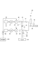
- FIG. 2 is a block diagram schematically illustrating an example of the descaling system according to the embodiment.
- the descaling system 20 includes a pump 40, an electric motor 41, a drive device 42, a connection pipe 43, a branch pipe 44, a valve 45, a pressure gauge 46, and a check valve 47. And further comprising.
- the arrow on the piping path represents the direction in which water flows.
- the pump 40 is provided between the water supply source WS and the common pipe 28.
- the pump 40 is connected to an electric motor 41.
- the electric motor 41 supplies driving force to the pump 40.
- the pump 40 is driven according to the driving force supplied from the electric motor 41, and supplies the common pipe 28 with a predetermined pressure and flow rate to the water from the water supply source WS. That is, the pump 40 supplies high-pressure water to each of the descaling headers 22a, 24a, and 26a to 26d via the common pipe 28.
- a spiral pump is used as the pump 40.
- the electric motor 41 supplies a driving force for rotating the impeller of the pump 40 to the pump 40, and drives the pump 40 by rotating the impeller.
- the supply of the driving force to the pump 40 is not limited to the electric motor 41, and other power sources such as a hydraulic actuator may be used, for example.
- the power source may be selected according to the type of pump 40.
- the power source may be incorporated in the pump 40.
- the electric motor 41 is electrically connected to the driving device 42.
- the drive device 42 controls the operation of the electric motor 41.
- the drive device 42 controls the rotation speed of the electric motor 41 by, for example, a voltage applied to the electric motor 41.
- the drive device 42 controls the drive of the pump 40.
- the driving device 42 controls the pressure of the high-pressure water supplied to each descaling header 22a, 24a, 26a to 26d.
- an inverter circuit is used for the driving device 42.
- connection pipe 43 is provided between the pump 40 and the common pipe 28.
- the connection pipe 43 is connected to each of the pump 40 and the common pipe 28.
- the connection pipe 43 sends the high-pressure water supplied from the pump 40 to the common pipe 28 and the descaling headers 22a, 24a, 26a to 26d. That is, the pump 40 supplies high-pressure water to each of the descaling headers 22a, 24a, 26a to 26d via the connection pipe 43 and the common pipe 28.
- the branch pipe 44 is connected to the connection pipe 43.
- the valve 45 is provided on the piping path of the branch pipe 44.
- the valve 45 controls the opening and closing of the branch pipe 44. Thereby, when the valve 45 is closed, the high-pressure water supplied from the pump 40 is supplied to the common pipe 28 via the connection pipe 43. On the other hand, when the valve 45 is opened, the high-pressure water supplied from the pump 40 is discharged to the outside through the branch pipe 44. For example, water supplied from the pump 40 is discharged to the pit 48 through the branch pipe 44.
- the valve 45 switches between supply of the high-pressure water to the common pipe 28 side and discharge of the high-pressure water. For example, a relief valve or a minimum flow valve is used as the valve 45.
- the pressure gauge 46 measures the pressure on the discharge side of the pump 40. In other words, the pressure gauge 46 measures the pressure in the connection pipe 43.
- the opening and closing of the valve 45 is controlled by, for example, the pressure value on the discharge side of the pump 40 measured by the pressure gauge 46. For example, when the descaling headers 22a, 24a, 26a to 26d on the rolling line are not used, the valve 45 is opened when the pressure exceeding a certain value is measured, and the high-pressure water is released to the branch pipe 44.
- the check valve 47 is provided on the pipe path of the connection pipe 43. That is, the check valve 47 is provided on the discharge side of the pump 40.
- the check valve 47 is provided, for example, at a portion between the branch pipe 44 and the common pipe 28 of the connection pipe 43.
- the check valve 47 suppresses the backflow of high pressure water.
- the check valve 47 suppresses the flow of water from the common pipe 28 side toward the pump 40.
- a plurality of pumps 40, electric motors 41, drive devices 42, connection pipes 43, branch pipes 44, valves 45, pressure gauges 46, and check valves 47 are provided in the descaling system 20.
- the pressure of the high-pressure water is controlled by driving a plurality of pumps 40.
- energy saving is achieved by controlling the operation of each pump 40 and each electric motor 41 in accordance with the required pressure.
- the number of pumps 40 and the like provided in the descaling system 20 may be arbitrarily set according to the required pressure.
- the number of pumps 40 and the like provided in the descaling system 20 may be one, for example. Energy saving may be achieved by switching between high-speed operation and standby operation of one pump 40.
- the plurality of connection pipes 43 are connected in parallel to the common pipe 28.
- the plurality of pumps 40 are connected to each of the plurality of connection pipes 43.
- the plurality of driving devices 42 control the driving of the plurality of pumps 40.
- the plurality of branch pipes 44 are connected to each of the plurality of connection pipes 43.
- the plurality of valves 45 are provided in each of the plurality of branch pipes 44 and control the opening and closing of each of the plurality of branch pipes 44.
- each of the plurality of pumps 40 for example, pumps having the same rating are used.
- each of the plurality of electric motors 41 for example, electric motors having the same rating are used. Thereby, for example, variation in pressure of water supplied from each pump 40 is suppressed.
- a plurality of pumps 40 and a plurality of electric motors 41 are connected in parallel to the common pipe 28. Thereby, compared with the case where it connects in series, the pressure of the common piping 28 becomes easy to control.
- the descaling system 20 further includes an accumulator 34.
- the accumulator 34 is provided on the pipe path of the common pipe 28.
- the accumulator 34 is provided between each descaling header 22a, 24a, 26a to 26d and each check valve 47, for example.
- the accumulator 34 suppresses the pressure pulsation of water in the common pipe 28.
- the descaling system 20 is provided with a large capacity accumulator 34. Thereby, for example, even when the supply of high-pressure water from each pump 40 is insufficient due to the injection of water from each descaling header 22a, 24a, 26a to 26d, the high-pressure water in the accumulator 34 is discharged, It can compensate for the temporary pressure drop and water drop.
- FIG. 3 is a block diagram schematically illustrating an example of the descaling system according to the embodiment.
- the descaling system 20 further includes a control device 50.
- the control device 50 includes a data collection unit 51, a pressure calculation unit 52, a pump control unit 53, and a protection unit 54.
- the data collection unit 51, the pressure calculation unit 52, the pump control unit 53, and the protection unit 54 may be provided in one device, or may be independent devices.
- the data collection unit 51 collects data from the rolling control system 60 of the rolling line 10 and stores it.
- the rolling control system 60 is, for example, a host system that controls rolling of the material 2a to be rolled by the rolling line 10.
- the data collecting unit 51 collects common pipe pressure information 61, rolled material position information 62, and rolled material information 63.
- the common pipe pressure information 61 indicates the pressure in the common pipe 28.
- the common pipe pressure information 61 is measured by the pressure gauge 30 of the common pipe 28 and input to the data collection unit 51.
- the material to be rolled position information 62 is information indicating a position on the rolling line 10 of the material to be rolled 2a.
- the material to be rolled position information 62 starts from a point extracted from the heating furnace 12, for example.
- the material to be rolled material information 63 indicates the material of the material to be rolled 2a.
- the material to be rolled material information 63 represents physical properties such as the surface and strength when each rolled material 2a becomes a final product.
- the material of the material 2a to be rolled has already been determined before the material 2a is rolled.
- the pressure calculation unit 52 Based on the collected common pipe pressure information 61, the material to be rolled position information 62, and the material to be rolled material information 63, the pressure calculation unit 52 has the common pipe 28 satisfying a desired scale removal performance for each material to be rolled 2a. Calculate the pressure.
- the material to be rolled 2 a of a different material such as iron or stainless steel is rolled.
- the material of the material 2a to be rolled is different, for example, the number of times of reverse rolling by the rough rolling mill 14 and the conveying speed at the time of rolling are different.
- the number of descaling headers 22a used in the HSB 22 and the number of descaling headers 24a used in the FSB 24 differ depending on the material to be rolled 2a. That is, the spray pattern of high-pressure water by the descaling headers 22a, 24a, 26a to 26d varies depending on the material of the material to be rolled 2a.
- the pressure calculation unit 52 specifies the injection pattern of high-pressure water by each descaling header 22a, 24a, 26a to 26d based on the material information 63 to be rolled. And the pressure calculation part 52 specifies the position of the to-be-rolled material 2a based on the to-be-rolled material position information 62, for example, and each descaling header 22a, 24a from the position of the to-be-rolled material 2a and the specified injection pattern. , 26a to 26d are predicted.
- the pressure calculation unit 52 calculates the necessary pressure in the common pipe 28 from the injection timing. Further, the pressure calculation unit 52 acquires the current pressure in the common pipe 28 based on the common pipe pressure information 61. Thereby, the pressure calculation unit 52 calculates the pressure of the common pipe 28 based on the common pipe pressure information 61, the material to be rolled position information 62, and the material to be rolled material information 63.
- the pump control unit 53 calculates an operation pattern of the pump 40 that can maintain the pressure of the common pipe 28 calculated by the pressure calculation unit 52. Then, the pump control unit 53 gives the calculated operation pattern to the drive device 42 of the descaling system 20 as an operation pattern command of the pump 40.
- the pump operation pattern is a combination of a pump 40 that requires high speed operation and a pump 40 that can be operated at a standby speed among a plurality of pumps 40.
- An operation pattern shows the timing which sets the pump 40 to high-speed operation, and the timing which sets the pump 40 to standby operation, for example.
- the pump control unit 53 calculates the operation pattern of each of the plurality of pumps 40 and inputs the calculation result to each driving device 42 corresponding to each pump 40.
- Each drive device 42 controls the operation of the electric motor 41 according to the input operation pattern.
- Each drive device 42 switches between high-speed operation and standby operation of the pump 40 according to the operation pattern, for example.
- the high-speed operation is, for example, an operation in which the electric motor 41 (pump 40) is rotated at the rotational speed of the rated operation.
- the standby operation is, for example, an operation in which the electric motor 41 is rotated at a rotation speed of about 50% when the rotation speed of the rated operation of the electric motor 41 is 100%.
- the high speed operation is, for example, an operation in which the drive amount of the pump 40 is set to the first value.
- the standby operation is an operation for setting the drive amount of the pump 40 to a second value lower than the first value, for example.
- the first value is, for example, a driving amount of 100%.
- the second value is, for example, a driving amount of 50%.
- the driving amount of the pump 40 is, for example, the rotational speed of the pump 40.
- the driving amount of the pump 40 may be determined according to the type of the pump 40.
- the pump 40 If the operation of the pump 40 is completely stopped, it takes time to return to high-speed operation, and there is a possibility that the required pressure cannot be obtained when high-pressure water is injected from the descaling header. For this reason, also in standby operation, the pump 40 and the electric motor 41 are operated at a certain rotational speed. When changing from standby operation to high-speed operation, the time to reach high-speed operation is calculated, and the operation of the motor 41 is switched earlier by the time than the timing of actual injection. Thereby, high-pressure water can be injected at a desired pressure while saving energy.
- the rotation speed of the electric motor 41 in the standby operation may be an arbitrary rotation speed at which a pressure required for jetting high-pressure water is obtained.
- the rotational speed of the electric motor 41 during standby operation may be arbitrarily set from a plurality of types, such as 85%, 70%, and 55%.
- the rotational speed of the electric motor 41 in the standby operation may be arbitrarily changed according to the required high-pressure water pressure.
- the protection unit 54 is electrically connected to the pump control unit 53 and each valve 45.
- the pump control unit 53 inputs the calculated operation pattern of each pump 54 to each driving device 42 and also inputs it to the protection unit 54.
- the protection unit 54 calculates the operation amount for the valve 45 attached between the pump 40 and the common pipe 28 from the operation pattern command. The protection unit 54 calculates the operation amount of each valve 45 from each operation pattern. The protection unit 54 inputs the calculated operation amount to each valve 45 and controls the opening and closing of each valve 45.
- the protection unit 54 closes the valve 45 corresponding to the pump 40 set to high speed operation, and opens the valve 45 corresponding to the pump 40 set to standby operation. For example, the protection unit 54 closes the valve 45 when the driving amount of the pump 40 is the first value, and opens the valve 45 when the driving amount of the pump 40 is the second value. In other words, the protection unit 54 closes the valve 45 when the driving amount of the pump 40 is the first value, and opens the valve 45 when the driving amount of the pump 40 is less than the first value. Thereby, the protection unit 54 protects the pumps 40 and the pipes around the pumps 40 (the connection pipes 43, the branch pipes 44, etc.) constituting the descaling system 20 in the control device 50.
- the protection unit 54 protects the pumps 40 and the pipes around the pumps 40 (the connection pipes 43, the branch pipes 44, etc.) constituting the descaling system 20 in the control device 50.
- the opening amount of the valve 45 may be changed according to the rotational speed of the electric motor 41.
- the opening amount of the valve 45 may be increased when the rotation speed of the electric motor 41 is relatively high, and the opening amount of the valve 45 may be decreased when the rotation speed of the electric motor 41 is relatively low.
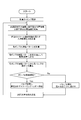
- FIG. 4 is a flowchart schematically illustrating an example of a processing flow of the control device according to the embodiment.
- FIG. 5 is a timing chart schematically showing an example of the operation pattern of each pump.
- calculation timing is a calculation interval of the control device 50.
- the operation pattern command for each pump 40 changes at every calculation interval. Basically, a certain time interval is set.
- the data collection unit 51 obtains the common pipe pressure information 61 from the pressure gauge 30 installed in the common pipe 28 and collects the material to be rolled position information 62 and the material information 63 to be rolled from the rolling control system 60. To do.
- the position of the material 2a to be rolled is known from the material information 62 to be rolled.
- the pressure calculation unit 52 determines the passage of the acceleration point of the pump 40 of the material 2a to be rolled based on the material position information 62 and controls the acceleration timing for the pump 40. That is, the pressure calculation unit 52 determines the injection timing of each descaling header 22a, 24a, 26a to 26d based on the rolled material position information 62. And the pressure calculation part 52 calculates the common piping pressure which satisfy
- the pump control unit 53 calculates an operation pattern of a plurality of pumps 40 that can maintain the pressure of the common pipe 28 calculated by the pressure calculation unit 52.
- the operation pattern is a combination of the number of pumps 40 operating in high speed operation (100% speed) and the number of pumps 40 operating in standby operation among a plurality of pumps 40. is there.
- the rotational speed of the pump 40 in the standby operation is, for example, about 50%.
- the rotation speed during standby operation can be determined by, for example, an end user.
- the pump control unit 53 realizes the operation pattern of each pump 40 by sending the calculated operation pattern to each drive device 42 as an operation command of each pump 40 and controlling acceleration / deceleration of each electric motor 41.
- the pump control unit 53 inputs the calculated operation pattern to the protection unit 54.
- the protection unit 54 calculates the operation amount of each valve 45 from the operation pattern command, and controls the opening and closing of each valve 45.
- the protection unit 54 closes the valve 45 corresponding to the pump 40 and sends the high-pressure water supplied from the pump 40 to each descaling header 22a, 24a, 26a to 26d.
- the protection unit 54 opens the valve 45 corresponding to the pump 40 and allows the high-pressure water supplied from the pump 40 to escape to the pit 48.
- the acceleration / deceleration of each pump 40 is controlled according to the operation pattern calculated by the pump control unit 53.
- the descaling system 20 controls the opening and closing of each valve 45 according to the operation pattern. Thereby, it can suppress that each pump 40 will be in a cutoff operation state. For example, it is possible to suppress a reduction in equipment life of each pump 40, each connection pipe 43, and each branch pipe 44.
- variable speed operation of all the pumps 40 among the plurality of pumps 40 has been taken as an example, but only one of the n pumps may be operated at a variable speed, Up to n-1 units may be operated at variable speed.
- a descaling system, a control device and a control method thereof that can save energy while maintaining the descaling performance of the descaling system for each material and have a long life.
- each of descaling header, common piping, connection piping, pump, driving device, branch piping, valve, control device, data collection unit, pressure calculation unit, pump control unit, protection unit, etc. included in the descaling system The specific configuration of the elements is included in the scope of the present invention as long as a person skilled in the art can appropriately perform the present invention by selecting appropriately from a known range and obtain the same effect. Moreover, what combined any two or more elements of each specific example in the technically possible range is also included in the scope of the present invention as long as the gist of the present invention is included.
Landscapes
- Engineering & Computer Science (AREA)
- Mechanical Engineering (AREA)
- Control Of Positive-Displacement Pumps (AREA)
- Cleaning By Liquid Or Steam (AREA)
- Control Of Metal Rolling (AREA)
Abstract
Description
なお、図面は模式的または概念的なものであり、各部分の厚みと幅との関係、部分間の大きさの比率などは、必ずしも現実のものと同一とは限らない。また、同じ部分を表す場合であっても、図面により互いの寸法や比率が異なって表される場合もある。
なお、本願明細書と各図において、既出の図に関して前述したものと同様の要素には同一の符号を付して詳細な説明は適宜省略する。
図1に表したように、圧延ライン10は、加熱炉12と、粗圧延機14と、仕上圧延機16と、巻取機18と、デスケーリングシステム20と、を備える。圧延ライン10は、熱間圧延を行うラインである。
図2に表したように、デスケーリングシステム20は、ポンプ40と、電動機41と、駆動装置42と、接続配管43と、分岐配管44と、バルブ45と、圧力計46と、逆止弁47と、をさらに備える。なお、図において、配管経路上の矢印は、水の流れる方向を表している。
図3に表したように、デスケーリングシステム20は、制御装置50をさらに備える。制御装置50は、データ収集部51と、圧力計算部52と、ポンプ制御部53と、保護部54と、を備える。データ収集部51、圧力計算部52、ポンプ制御部53及び保護部54の各部は、1つの装置内に設けてもよいし、それぞれを独立した装置としてもよい。
図4は、実施形態に係る制御装置の処理フローの一例を模式的に表すフローチャートである。
図5は、各ポンプの運転パターンの一例を模式的に表すタイミングチャートである。
図4に表したように、制御装置50の動作においては、まず、計算タイミングを設定する。計算タイミングとは、制御装置50の計算間隔である。各ポンプ40に対する運転パターン指令は、計算間隔毎に変化する。基本的に一定時間間隔を設定する。
また、各具体例のいずれか2つ以上の要素を技術的に可能な範囲で組み合わせたものも、本発明の要旨を包含する限り本発明の範囲に含まれる。
Claims (8)
- 圧延ラインに設けられた複数のデスケーリングヘッダと、
前記複数のデスケーリングヘッダのそれぞれに接続された共通配管と、
前記共通配管に接続された接続配管と、
前記接続配管に接続され、前記接続配管及び前記共通配管を介して前記複数のデスケーリングヘッダのそれぞれに高圧水を供給するポンプと、
前記ポンプの駆動を制御する駆動装置と、
前記接続配管に接続された分岐配管と、
前記分岐配管に設けられ、前記分岐配管の開閉を制御するバルブと、
制御装置であって、
前記共通配管内の圧力を示す共通配管圧力情報と、被圧延材の前記圧延ライン上の位置を示す被圧延材位置情報と、前記被圧延材の材質を示す被圧延材材質情報と、を収集するデータ収集部と、
前記共通配管圧力情報と前記被圧延材位置情報と前記被圧延材材質情報とを基に、前記被圧延材に対する所望のスケール除去性能を満たす前記共通配管内の前記圧力を計算する圧力計算部と、
計算した前記共通配管内の前記圧力を保てる前記ポンプの運転パターンを計算し、前記運転パターンを前記駆動装置に入力するポンプ制御部と、
前記運転パターンを基に前記バルブの操作量を計算し、前記操作量に応じて前記バルブの開閉を制御する保護部と、
を含む制御装置と、
を備えたデスケーリングシステム。 - 前記接続配管、前記ポンプ、前記駆動装置、前記分岐配管及び前記バルブのそれぞれは、複数設けられ、
前記複数の接続配管は、前記共通配管に対して並列に接続され、
前記複数のポンプは、前記複数の接続配管のそれぞれに接続され、
前記複数の駆動装置は、前記複数のポンプのそれぞれの駆動を制御し、
前記複数の分岐配管は、前記複数の接続配管のそれぞれに接続され、
前記複数のバルブは、前記複数の分岐配管のそれぞれに設けられ、前記複数の分岐配管のそれぞれの開閉を制御し、
前記ポンプ制御部は、前記複数のポンプのそれぞれに対応する複数の前記運転パターンを計算し、
前記保護部は、前記複数の運転パターンを基に前記複数のバルブのそれぞれに対応する複数の前記操作量を計算し、前記複数の操作量に応じて前記複数のバルブのそれぞれの開閉を制御する請求項1記載のデスケーリングシステム。 - 前記ポンプ制御部は、前記複数の運転パターンのそれぞれを前記複数の駆動装置のそれぞれに入力する請求項2記載のデスケーリングシステム。
- 前記運転パターンは、前記ポンプを高速運転に設定するタイミング及び前記ポンプを待機運転に設定するタイミングを示し、
前記保護部は、前記ポンプが前記高速運転に設定されている時に前記バルブを閉じ、前記ポンプが前記待機運転に設定されている時に前記バルブを開く前記操作量を計算する請求項1記載のデスケーリングシステム。 - 前記共通配管内の圧力を計測する圧力計をさらに備え、
前記データ収集部は、前記圧力計から前記共通配管圧力情報を収集する請求項1記載のデスケーリングシステム。 - 前記接続配管の前記分岐配管と前記共通配管との間の部分に設けられた逆止弁をさらに備えた請求項1記載のデスケーリングシステム。
- 圧延ラインに設けられた複数のデスケーリングヘッダと、
前記複数のデスケーリングヘッダのそれぞれに接続された共通配管と、
前記共通配管に接続された接続配管と、
前記接続配管に接続され、前記接続配管及び前記共通配管を介して前記複数のデスケーリングヘッダのそれぞれに高圧水を供給するポンプと、
前記ポンプの駆動を制御する駆動装置と、
前記接続配管に接続された分岐配管と、
前記分岐配管に設けられ、前記分岐配管の開閉を制御するバルブと、
を備えたデスケーリングシステムの制御装置において、
前記共通配管内の圧力を示す共通配管圧力情報と、被圧延材の前記圧延ライン上の位置を示す被圧延材位置情報と、前記被圧延材の材質を示す被圧延材材質情報と、を収集するデータ収集部と、
前記共通配管圧力情報と前記被圧延材位置情報と前記被圧延材材質情報とを基に、前記被圧延材に対する所望のスケール除去性能を満たす前記共通配管内の前記圧力を計算する圧力計算部と、
計算した前記共通配管内の前記圧力を保てる前記ポンプの運転パターンを計算し、前記運転パターンを前記駆動装置に入力するポンプ制御部と、
前記運転パターンを基に前記バルブの操作量を計算し、前記操作量に応じて前記バルブの開閉を制御する保護部と、
を備えたデスケーリングシステムの制御装置。 - 圧延ラインに設けられた複数のデスケーリングヘッダと、
前記複数のデスケーリングヘッダのそれぞれに接続された共通配管と、
前記共通配管に接続された接続配管と、
前記接続配管に接続され、前記接続配管及び前記共通配管を介して前記複数のデスケーリングヘッダのそれぞれに高圧水を供給するポンプと、
前記ポンプの駆動を制御する駆動装置と、
前記接続配管に接続された分岐配管と、
前記分岐配管に設けられ、前記分岐配管の開閉を制御するバルブと、
を備えたデスケーリングシステムの制御方法において、
前記共通配管内の圧力を示す共通配管圧力情報と、被圧延材の前記圧延ライン上の位置を示す被圧延材位置情報と、前記被圧延材の材質を示す被圧延材材質情報と、を収集する工程と、
前記共通配管圧力情報と前記被圧延材位置情報と前記被圧延材材質情報とを基に、前記被圧延材に対する所望のスケール除去性能を満たす前記共通配管内の前記圧力を計算する工程と、
計算した前記共通配管内の前記圧力を保てる前記ポンプの運転パターンを計算し、前記運転パターンを前記駆動装置に入力する工程と、
前記運転パターンを基に前記バルブの操作量を計算し、前記操作量に応じて前記バルブの開閉を制御する工程と、
を備えたデスケーリングシステムの制御方法。
Priority Applications (5)
| Application Number | Priority Date | Filing Date | Title |
|---|---|---|---|
| PCT/JP2015/053530 WO2016129040A1 (ja) | 2015-02-09 | 2015-02-09 | デスケーリングシステム及びその制御装置及び制御方法 |
| US15/549,574 US10695810B2 (en) | 2015-02-09 | 2015-02-09 | Descaling system, control device of the descaling system, and method for controlling the descaling system |
| JP2016574543A JP6373416B2 (ja) | 2015-02-09 | 2015-02-09 | デスケーリングシステム及びその制御装置及び制御方法 |
| CN201580075752.7A CN107249767B (zh) | 2015-02-09 | 2015-02-09 | 除锈系统及其控制装置及控制方法 |
| TW104116202A TWI615212B (zh) | 2015-02-09 | 2015-05-21 | 除銹系統及其控制裝置及控制方法 |
Applications Claiming Priority (1)
| Application Number | Priority Date | Filing Date | Title |
|---|---|---|---|
| PCT/JP2015/053530 WO2016129040A1 (ja) | 2015-02-09 | 2015-02-09 | デスケーリングシステム及びその制御装置及び制御方法 |
Publications (1)
| Publication Number | Publication Date |
|---|---|
| WO2016129040A1 true WO2016129040A1 (ja) | 2016-08-18 |
Family
ID=56615124
Family Applications (1)
| Application Number | Title | Priority Date | Filing Date |
|---|---|---|---|
| PCT/JP2015/053530 Ceased WO2016129040A1 (ja) | 2015-02-09 | 2015-02-09 | デスケーリングシステム及びその制御装置及び制御方法 |
Country Status (5)
| Country | Link |
|---|---|
| US (1) | US10695810B2 (ja) |
| JP (1) | JP6373416B2 (ja) |
| CN (1) | CN107249767B (ja) |
| TW (1) | TWI615212B (ja) |
| WO (1) | WO2016129040A1 (ja) |
Cited By (1)
| Publication number | Priority date | Publication date | Assignee | Title |
|---|---|---|---|---|
| JP2018125945A (ja) * | 2017-01-31 | 2018-08-09 | 東芝三菱電機産業システム株式会社 | 電動機可変速駆動装置用冷却システム |
Families Citing this family (5)
| Publication number | Priority date | Publication date | Assignee | Title |
|---|---|---|---|---|
| CN111083924A (zh) * | 2018-08-20 | 2020-04-28 | 东芝三菱电机产业系统株式会社 | 除锈装置用泵系统的控制装置 |
| CN111715711B (zh) * | 2020-05-06 | 2022-03-29 | 唐山钢铁集团有限责任公司 | 一种热轧板带产线高效除鳞控制方法 |
| EP4015099B1 (de) * | 2020-12-15 | 2024-10-16 | Primetals Technologies Austria GmbH | Energieeffiziente herstellung eines ferritischen warmbands in einer giess-walz-verbundanlage |
| CN113042553B (zh) * | 2021-02-25 | 2023-02-17 | 首钢京唐钢铁联合有限责任公司 | 一种热轧的精除鳞装置及热轧生产线 |
| CN115229641B (zh) * | 2022-09-22 | 2023-12-29 | 南通速维工程设备有限公司 | 一种机器人压力管道除锈控制方法及系统 |
Citations (3)
| Publication number | Priority date | Publication date | Assignee | Title |
|---|---|---|---|---|
| JPH11104729A (ja) * | 1997-10-06 | 1999-04-20 | Kawasaki Steel Corp | 熱間鋼材のデスケーリング方法および装置 |
| JPH11156426A (ja) * | 1997-11-25 | 1999-06-15 | Hitachi Ltd | デスケーリング装置及びデスケーリング方法 |
| JP2013158832A (ja) * | 2012-02-09 | 2013-08-19 | Toshiba Mitsubishi-Electric Industrial System Corp | 圧延デスケーリング装置の制御装置 |
Family Cites Families (24)
| Publication number | Priority date | Publication date | Assignee | Title |
|---|---|---|---|---|
| US3779054A (en) * | 1972-03-02 | 1973-12-18 | Wean United Inc | Coolant control for hot strip mill |
| US4132393A (en) * | 1976-06-30 | 1979-01-02 | Nippon Steel Corporation | Apparatus for cooling hot steel plate and sheet |
| JPS6020090B2 (ja) * | 1979-10-05 | 1985-05-20 | 新日本製鐵株式会社 | 板材の冷却注水装置 |
| JPS5848019B2 (ja) * | 1979-11-09 | 1983-10-26 | 石川島播磨重工業株式会社 | 鋼板の噴霧冷却方法及びその装置 |
| JPS58185306U (ja) * | 1982-05-31 | 1983-12-09 | 株式会社日立製作所 | デスケ−リングポンプの流量制御装置 |
| JPH01178305A (ja) * | 1988-01-06 | 1989-07-14 | Hitachi Ltd | ロールクーラントのスプレー制御装置 |
| US5235840A (en) * | 1991-12-23 | 1993-08-17 | Hot Rolling Consultants, Ltd. | Process to control scale growth and minimize roll wear |
| JP3307771B2 (ja) * | 1993-08-23 | 2002-07-24 | ハンス‐ユルゲン、ガイドール | 熱間圧延鋼板のデスケーリング手段 |
| US5661884A (en) * | 1996-02-20 | 1997-09-02 | Tippins Incorporated | Offset high-pressure water descaling system |
| JP2000288620A (ja) | 1999-03-31 | 2000-10-17 | Kawasaki Steel Corp | 鋼の熱間圧延におけるデスケーリングポンプの運転方法 |
| JP4062823B2 (ja) * | 1999-07-12 | 2008-03-19 | 株式会社豊田自動織機 | ウオータジェットルームにおける緯入れ水切り換え装置 |
| DE10110324A1 (de) * | 2001-03-03 | 2002-09-05 | Sms Demag Ag | Verfahren zum Entzundern von Bändern |
| JP2003101199A (ja) | 2001-09-25 | 2003-04-04 | Tokyo Kakoki Kk | 洗浄装置 |
| JP4145183B2 (ja) * | 2003-04-02 | 2008-09-03 | ナスコフィッティング株式会社 | 管継手 |
| JP4426363B2 (ja) * | 2004-04-08 | 2010-03-03 | 株式会社山武 | 送水制御装置およびその方法 |
| CN100411763C (zh) * | 2005-12-09 | 2008-08-20 | 广东韶钢松山股份有限公司 | 高压水除鳞系统 |
| JP2009030821A (ja) * | 2007-07-24 | 2009-02-12 | Yamatake Corp | 送水制御システムおよび送水制御方法 |
| AT507663B1 (de) * | 2009-04-09 | 2010-07-15 | Siemens Vai Metals Tech Gmbh | Verfahren und vorrichtung zum aufbereiten von warmwalzgut |
| CN201524703U (zh) * | 2009-05-26 | 2010-07-14 | 广州金关节能科技发展有限公司 | 多段除鳞节能控制装置 |
| CN201969738U (zh) * | 2010-11-12 | 2011-09-14 | 北京工业大学 | 一种高压水射流带钢清洗装置 |
| JP5684616B2 (ja) * | 2011-03-16 | 2015-03-18 | 東芝三菱電機産業システム株式会社 | デスケーリングシステム |
| JP5795924B2 (ja) | 2011-09-26 | 2015-10-14 | 東芝三菱電機産業システム株式会社 | 最適化装置、最適化方法、及び最適化プログラム |
| CN102755997A (zh) * | 2012-07-26 | 2012-10-31 | 宝钢不锈钢有限公司 | 热轧高压除鳞系统的安全节能控制装置及其控制方法 |
| GB2514599B (en) * | 2013-05-30 | 2015-07-08 | Siemens Vai Metals Tech Gmbh | Adjustable descaler |
-
2015
- 2015-02-09 CN CN201580075752.7A patent/CN107249767B/zh active Active
- 2015-02-09 JP JP2016574543A patent/JP6373416B2/ja active Active
- 2015-02-09 WO PCT/JP2015/053530 patent/WO2016129040A1/ja not_active Ceased
- 2015-02-09 US US15/549,574 patent/US10695810B2/en active Active
- 2015-05-21 TW TW104116202A patent/TWI615212B/zh active
Patent Citations (3)
| Publication number | Priority date | Publication date | Assignee | Title |
|---|---|---|---|---|
| JPH11104729A (ja) * | 1997-10-06 | 1999-04-20 | Kawasaki Steel Corp | 熱間鋼材のデスケーリング方法および装置 |
| JPH11156426A (ja) * | 1997-11-25 | 1999-06-15 | Hitachi Ltd | デスケーリング装置及びデスケーリング方法 |
| JP2013158832A (ja) * | 2012-02-09 | 2013-08-19 | Toshiba Mitsubishi-Electric Industrial System Corp | 圧延デスケーリング装置の制御装置 |
Cited By (1)
| Publication number | Priority date | Publication date | Assignee | Title |
|---|---|---|---|---|
| JP2018125945A (ja) * | 2017-01-31 | 2018-08-09 | 東芝三菱電機産業システム株式会社 | 電動機可変速駆動装置用冷却システム |
Also Published As
| Publication number | Publication date |
|---|---|
| TW201628730A (zh) | 2016-08-16 |
| US20180021825A1 (en) | 2018-01-25 |
| JPWO2016129040A1 (ja) | 2017-11-16 |
| TWI615212B (zh) | 2018-02-21 |
| CN107249767A (zh) | 2017-10-13 |
| JP6373416B2 (ja) | 2018-08-15 |
| US10695810B2 (en) | 2020-06-30 |
| CN107249767B (zh) | 2019-03-01 |
Similar Documents
| Publication | Publication Date | Title |
|---|---|---|
| JP6373416B2 (ja) | デスケーリングシステム及びその制御装置及び制御方法 | |
| JP5790528B2 (ja) | 圧延デスケーリング装置の制御装置 | |
| KR101424905B1 (ko) | 압연 라인에서의 물 분사 제어 장치, 물 분사 제어 방법, 물 분사 제어 프로그램 | |
| KR101331324B1 (ko) | 다중 스탠드 압연 트레인을 통과하는 압연 재료의 배출 두께 조정 방법, 개회로 제어 장치 및/또는 폐회로 제어 장치 및 압연 설비 | |
| CN102176984A (zh) | 具有转速可变的泵驱动装置的除鳞设备 | |
| JP6156493B2 (ja) | 電力管理装置 | |
| JP5684616B2 (ja) | デスケーリングシステム | |
| JP5994999B2 (ja) | 熱間圧延ラインの冷却装置の制御方法 | |
| JP2004136291A (ja) | 熱間圧延ラインにおけるストリップの温度制御装置、方法、コンピュータプログラム、及びコンピュータ読み取り可能な記憶媒体 | |
| CN103764306B (zh) | 轧制设备的节能装置 | |
| JP5768467B2 (ja) | 熱間圧延ラインにおける圧延鋼板の仕上げ出側温度制御方法 | |
| JP2012163279A (ja) | 給水流量制御装置、及びこれを用いた発電プラント | |
| WO2014050200A1 (ja) | 熱源システム制御装置 | |
| TW202030415A (zh) | 揚水泵的速度控制裝置 | |
| CN103261980B (zh) | 轧机设备能耗降低方法,控制和/或调节装置及轧机设备 | |
| CN111670537B (zh) | 用于加工工件的装置 | |
| JP4079098B2 (ja) | 熱延鋼板の製造方法及び製造装置 | |
| JP5985330B2 (ja) | 給水装置および給水装置の運転方法 | |
| JP2011056401A (ja) | 水処理設備用の制御装置 | |
| CN111083924A (zh) | 除锈装置用泵系统的控制装置 | |
| JP6819627B2 (ja) | 圧延デスケーリング装置用ポンプ制御装置 | |
| CN113165036B (zh) | 温度控制系统 | |
| CN119216389A (zh) | 一种粗轧除鳞系统的控制方法及控制系统 | |
| JPS60255213A (ja) | 金属材料の熱間加工用デスケ−リング方法 | |
| WO2019111368A1 (ja) | 評価装置 |
Legal Events
| Date | Code | Title | Description |
|---|---|---|---|
| 121 | Ep: the epo has been informed by wipo that ep was designated in this application |
Ref document number: 15881915 Country of ref document: EP Kind code of ref document: A1 |
|
| ENP | Entry into the national phase |
Ref document number: 2016574543 Country of ref document: JP Kind code of ref document: A |
|
| WWE | Wipo information: entry into national phase |
Ref document number: 15549574 Country of ref document: US |
|
| NENP | Non-entry into the national phase |
Ref country code: DE |
|
| 122 | Ep: pct application non-entry in european phase |
Ref document number: 15881915 Country of ref document: EP Kind code of ref document: A1 |