WO2016125688A1 - 内燃機関の制御装置 - Google Patents
内燃機関の制御装置 Download PDFInfo
- Publication number
- WO2016125688A1 WO2016125688A1 PCT/JP2016/052565 JP2016052565W WO2016125688A1 WO 2016125688 A1 WO2016125688 A1 WO 2016125688A1 JP 2016052565 W JP2016052565 W JP 2016052565W WO 2016125688 A1 WO2016125688 A1 WO 2016125688A1
- Authority
- WO
- WIPO (PCT)
- Prior art keywords
- voltage
- fuel injection
- internal combustion
- combustion engine
- control device
- Prior art date
- Legal status (The legal status is an assumption and is not a legal conclusion. Google has not performed a legal analysis and makes no representation as to the accuracy of the status listed.)
- Ceased
Links
Images
Classifications
-
- F—MECHANICAL ENGINEERING; LIGHTING; HEATING; WEAPONS; BLASTING
- F02—COMBUSTION ENGINES; HOT-GAS OR COMBUSTION-PRODUCT ENGINE PLANTS
- F02D—CONTROLLING COMBUSTION ENGINES
- F02D41/00—Electrical control of supply of combustible mixture or its constituents
- F02D41/20—Output circuits, e.g. for controlling currents in command coils
-
- F—MECHANICAL ENGINEERING; LIGHTING; HEATING; WEAPONS; BLASTING
- F02—COMBUSTION ENGINES; HOT-GAS OR COMBUSTION-PRODUCT ENGINE PLANTS
- F02D—CONTROLLING COMBUSTION ENGINES
- F02D41/00—Electrical control of supply of combustible mixture or its constituents
- F02D41/30—Controlling fuel injection
- F02D41/38—Controlling fuel injection of the high pressure type
- F02D41/40—Controlling fuel injection of the high pressure type with means for controlling injection timing or duration
- F02D41/402—Multiple injections
-
- F—MECHANICAL ENGINEERING; LIGHTING; HEATING; WEAPONS; BLASTING
- F02—COMBUSTION ENGINES; HOT-GAS OR COMBUSTION-PRODUCT ENGINE PLANTS
- F02D—CONTROLLING COMBUSTION ENGINES
- F02D41/00—Electrical control of supply of combustible mixture or its constituents
- F02D41/20—Output circuits, e.g. for controlling currents in command coils
- F02D2041/2003—Output circuits, e.g. for controlling currents in command coils using means for creating a boost voltage, i.e. generation or use of a voltage higher than the battery voltage, e.g. to speed up injector opening
-
- F—MECHANICAL ENGINEERING; LIGHTING; HEATING; WEAPONS; BLASTING
- F02—COMBUSTION ENGINES; HOT-GAS OR COMBUSTION-PRODUCT ENGINE PLANTS
- F02D—CONTROLLING COMBUSTION ENGINES
- F02D41/00—Electrical control of supply of combustible mixture or its constituents
- F02D41/20—Output circuits, e.g. for controlling currents in command coils
- F02D2041/202—Output circuits, e.g. for controlling currents in command coils characterised by the control of the circuit
- F02D2041/2051—Output circuits, e.g. for controlling currents in command coils characterised by the control of the circuit using voltage control
-
- F—MECHANICAL ENGINEERING; LIGHTING; HEATING; WEAPONS; BLASTING
- F02—COMBUSTION ENGINES; HOT-GAS OR COMBUSTION-PRODUCT ENGINE PLANTS
- F02D—CONTROLLING COMBUSTION ENGINES
- F02D41/00—Electrical control of supply of combustible mixture or its constituents
- F02D41/20—Output circuits, e.g. for controlling currents in command coils
- F02D2041/202—Output circuits, e.g. for controlling currents in command coils characterised by the control of the circuit
- F02D2041/2058—Output circuits, e.g. for controlling currents in command coils characterised by the control of the circuit using information of the actual current value
-
- F—MECHANICAL ENGINEERING; LIGHTING; HEATING; WEAPONS; BLASTING
- F02—COMBUSTION ENGINES; HOT-GAS OR COMBUSTION-PRODUCT ENGINE PLANTS
- F02D—CONTROLLING COMBUSTION ENGINES
- F02D2200/00—Input parameters for engine control
- F02D2200/02—Input parameters for engine control the parameters being related to the engine
- F02D2200/06—Fuel or fuel supply system parameters
- F02D2200/0602—Fuel pressure
-
- F—MECHANICAL ENGINEERING; LIGHTING; HEATING; WEAPONS; BLASTING
- F02—COMBUSTION ENGINES; HOT-GAS OR COMBUSTION-PRODUCT ENGINE PLANTS
- F02D—CONTROLLING COMBUSTION ENGINES
- F02D2200/00—Input parameters for engine control
- F02D2200/50—Input parameters for engine control said parameters being related to the vehicle or its components
-
- F—MECHANICAL ENGINEERING; LIGHTING; HEATING; WEAPONS; BLASTING
- F02—COMBUSTION ENGINES; HOT-GAS OR COMBUSTION-PRODUCT ENGINE PLANTS
- F02D—CONTROLLING COMBUSTION ENGINES
- F02D41/00—Electrical control of supply of combustible mixture or its constituents
- F02D41/24—Electrical control of supply of combustible mixture or its constituents characterised by the use of digital means
- F02D41/26—Electrical control of supply of combustible mixture or its constituents characterised by the use of digital means using computer, e.g. microprocessor
-
- F—MECHANICAL ENGINEERING; LIGHTING; HEATING; WEAPONS; BLASTING
- F02—COMBUSTION ENGINES; HOT-GAS OR COMBUSTION-PRODUCT ENGINE PLANTS
- F02M—SUPPLYING COMBUSTION ENGINES IN GENERAL WITH COMBUSTIBLE MIXTURES OR CONSTITUENTS THEREOF
- F02M69/00—Low-pressure fuel-injection apparatus ; Apparatus with both continuous and intermittent injection; Apparatus injecting different types of fuel
- F02M69/04—Injectors peculiar thereto
- F02M69/042—Positioning of injectors with respect to engine, e.g. in the air intake conduit
- F02M69/046—Positioning of injectors with respect to engine, e.g. in the air intake conduit for injecting into both the combustion chamber and the intake conduit
-
- Y—GENERAL TAGGING OF NEW TECHNOLOGICAL DEVELOPMENTS; GENERAL TAGGING OF CROSS-SECTIONAL TECHNOLOGIES SPANNING OVER SEVERAL SECTIONS OF THE IPC; TECHNICAL SUBJECTS COVERED BY FORMER USPC CROSS-REFERENCE ART COLLECTIONS [XRACs] AND DIGESTS
- Y02—TECHNOLOGIES OR APPLICATIONS FOR MITIGATION OR ADAPTATION AGAINST CLIMATE CHANGE
- Y02T—CLIMATE CHANGE MITIGATION TECHNOLOGIES RELATED TO TRANSPORTATION
- Y02T10/00—Road transport of goods or passengers
- Y02T10/10—Internal combustion engine [ICE] based vehicles
- Y02T10/40—Engine management systems
Definitions
- the present invention relates to a control device for an internal combustion engine.
- the boosting power source is generally composed of a boosting circuit including an inductive element and a switching element, and a capacitor for storing boosted power.
- the fuel injection valve When the fuel injection valve is energized from the boost power source, electric power is supplied by the discharge from the capacitor. For this reason, when a current is supplied from the boosting power source, the voltage of the capacitor drops due to discharging.
- the electric power is charged by the booster circuit and returns to the boosted predetermined voltage.
- the charge may not be in time for the second and subsequent injections.
- Patent Document 1 there is known a fuel injection device that performs the maximum number of injections that can be performed for the required number of injections even when the boosted voltage is reduced (see, for example, Patent Document 1).
- Patent Document 1 the boosted voltage obtained by boosting the battery voltage by the engine controller unit is monitored, and when the boosted voltage drops below the set normal voltage, the valve opening time Pi of the fuel injector is extended, and the fuel injector A configuration that secures a drive current necessary for the operation of is described. Thereby, a highly reliable fuel injection device is realized.
- this effect is significant in the low injection pulse range (the range where the fuel injection pulse width is small), and correction control is required to suppress variations in the injection amount due to valve opening delay.
- delaying the injection timing in order to secure the charging time of the boosted voltage makes it possible to achieve both engine output, exhaust gas purification, and fuel efficiency improvement at a high level. Even if the required injection timing is set for this purpose, fuel injection cannot be executed at a desired timing.
- An object of the present invention is to provide a control device for an internal combustion engine that can suppress the above-mentioned problem.
- the present invention provides a battery for supplying a first voltage, a booster circuit for boosting the first voltage and supplying a boosted second voltage, and the second voltage.
- a fuel injection device that is driven by and injects fuel, a switch that turns on and off the second voltage supplied from the booster circuit to the fuel injection device, and an arithmetic device that controls the switch,
- the arithmetic unit is configured to estimate the second voltage at all fuel injection timings in the one combustion cycle before the first fuel injection in one combustion cycle; and the estimated second voltage And a correction unit for correcting the fuel injection amount at each fuel injection timing.
- FIG. 6 is a chart showing a relationship among a drive current of a fuel injection valve, a boosted voltage, and a return reference time. It is a chart which shows the relationship between the reset reference time of a battery voltage and a boost voltage. 4 is a chart showing a relationship between a boost voltage estimated value and a boost voltage estimation correction amount according to an embodiment of the present invention. It is a flowchart of the fuel injection control by embodiment of this invention.
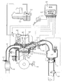
- FIG. 1 is a diagram showing a basic configuration of a system including an ECU according to an embodiment of the present invention.
- the air sucked into the internal combustion engine (101) passes through an air flow meter (AFM: Air Flow Meter) (120) and is sucked in the order of the throttle valve (119) and the collector (115). These are supplied to the combustion chamber (121) via the intake pipe (110) and the intake valve (103) provided in each cylinder.
- AFM Air Flow Meter
- the fuel is sent from the fuel tank (123) to the high-pressure fuel pump (125) provided in the internal combustion engine (101) by the low-pressure fuel pump (124), and the high-pressure fuel pump (125) is ECU (Engine Control Unit). Based on the control command value from (109), the fuel pressure is controlled to a desired pressure.
- the high pressure fuel is sent to the fuel injection valve (105: fuel injection device) via the high pressure fuel pipe (128), and the fuel injection valve (105) is a fuel injection provided in the ECU (109). Based on a command from the control device (127), fuel is injected into the combustion chamber (121).
- the internal combustion engine (101) is provided with a fuel pressure sensor (126) for measuring the pressure in the high-pressure fuel pipe (128) in order to control the high-pressure fuel pump (125), and the ECU (109) Based on this sensor value, so-called feedback control is generally performed so that the fuel pressure in the high-pressure fuel pipe (128) becomes a desired pressure. Further, the internal combustion engine (101) is provided with an ignition coil (107) and an ignition plug (106). The ECU (109) controls the energization of the ignition coil (107) at the desired timing and the ignition by the ignition plug (106). It is a mechanism for control.
- the intake air and the fuel are burned in the combustion chamber (121) by the spark emitted from the spark plug (106).
- the exhaust gas generated by the combustion is exhausted to the exhaust pipe (111) through the exhaust valve (104), and a three-way catalyst (112) for purifying the exhaust gas is disposed on the exhaust pipe (111). Is provided.
- the ECU (109) incorporates the above-described fuel injection control device (127), and a crank angle sensor (116) for measuring the crankshaft (not shown) angle of the internal combustion engine (101) detects the intake air amount ( AFM (120) to measure, oxygen sensor (113) to detect oxygen concentration in exhaust gas, accelerator position sensor (122) to detect accelerator position operated by driver, fuel pressure to detect fuel pressure A signal from the sensor (126) or the like is input.
- AFM intake air amount
- oxygen sensor 113
- accelerator position sensor (122) to detect accelerator position operated by driver
- fuel pressure to detect fuel pressure
- a signal from the sensor (126) or the like is input.
- the ECU (109) calculates the required torque of the internal combustion engine (101) from the signal of the accelerator opening sensor (122) and determines whether or not the engine is in an idle state. Further, the ECU (109) includes a rotation speed detection unit that calculates the rotation speed of the internal combustion engine (hereinafter referred to as engine rotation speed) from the signal of the crank angle sensor (116), and an internal combustion engine (108) obtained from the water temperature sensor (108). 101) and a means (determination unit) for determining whether or not the three-way catalyst (112) is in a warmed-up state based on the cooling water temperature and the elapsed time after starting the internal combustion engine.
- engine rotation speed the rotation speed of the internal combustion engine
- the ECU (109) calculates the intake air amount necessary for the internal combustion engine (101) from the above-described required torque and outputs an opening signal corresponding to the intake air amount to the throttle valve (119).
- the fuel injection control device (127) calculates a fuel amount corresponding to the intake air amount, outputs a fuel injection signal to the fuel injection valve (105), and further outputs an ignition signal to the ignition coil (107).
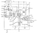
- FIG. 2 is a block diagram of the ECU (109) shown in FIG.
- the ECU (109) includes a power supply IC (203), a microcomputer (204), and a fuel injection control circuit (215).
- the power supply IC (203), the microcomputer (204), and the fuel injection control circuit (215) constitute a fuel injection control device (127).
- the fuel injection control circuit (215) is built in the ECU (109) and includes a driver IC (207), a booster circuit (211), an upper driver (212), and a lower driver (213).
- the battery voltage from the battery (201) which is a vehicle power supply is supplied to the ECU (109) and then supplied to the power supply IC (203).
- the battery voltage Vb is supplied to the driver IC (207) of the fuel injection control circuit (215), the booster circuit (211) for driving the fuel injection device, the upper driver (212), and the like.
- a voltage is supplied from the power supply IC (203) to the microcomputer (204), the driver IC (207) and the like as an arithmetic unit.
- the driver IC (207) of the fuel injection control circuit (215) includes a communication unit (209) with the microcomputer (204), a booster circuit drive unit (210), and a driver drive unit (208).
- the booster circuit driver (210) sends a switching signal to the booster circuit (211).
- the booster circuit (211) boosts the battery voltage Vb according to the switching signal, and supplies the boosted voltage Vboost to the upper driver (212).
- the voltage Vboost boosted by the booster circuit (211) is fed back to the booster circuit drive unit (210) of the driver IC (207). Accordingly, the driver IC (207) determines whether or not to send a switching signal again.
- the voltage Vboost boosted by the booster circuit (211) is fed back to the A / D converter (205) of the microcomputer (204).
- the microcomputer (204) can send a signal from the communication unit (206) to the driver IC (207) based on the A / D value.
- the microcomputer (204) receives signals from the fuel pressure sensor and temperature sensor (including the ambient temperature of the ECU (109), the substrate temperature, and the temperature of the booster circuit) in addition to the boosted voltage via the A / D converter (205). Can be input and monitored.
- the microcomputer (204) has an input / output port (202) for driving an external load and monitoring an external signal.
- the microcomputer (204) includes a ROM and a RAM (not shown), and has a function of storing set values and the like.
- the upper driver (212) of the fuel injection control circuit (215) includes a boost voltage driver (212a) for driving the coil load (214) by the boost voltage of the boost circuit (211), and a coil load by the battery voltage from the battery (201).
- the upper driver (212) supplies a current to a coil load (214) such as a fuel injection valve having an electromagnetic coil by the drive signal A and the drive signal B of the driver drive unit (208) of the driver IC (207).
- the drive signal A triggers the boost voltage driver (212a) by the boost voltage
- the drive signal B triggers the battery voltage driver (212b) by the battery voltage
- the lower driver (213) causes the current from the coil load (214) to flow to the ground potential by the drive signal C of the driver drive unit (208).
- At least one of the upper driver (212) and the lower driver (213) has a current detection unit and a terminal voltage detection unit using a shunt resistor or the like, and detects a current value flowing through the driver and the coil load (214).
- Driver drive control is performed to provide feedback. Also, it is possible to detect an overcurrent to the driver, a terminal power supply fault, and a ground fault with these functions.
- the booster circuit (211), the upper driver (212), and the lower driver (213) are provided separately from the driver IC (207), but these are provided inside the driver IC (207). Also good. That is, the driver IC (207) may be used as either a driver or a pre-driver.
- the upper driver (212) and the lower driver (213) function as switches that turn on / off the boosted voltage supplied from the booster circuit (211) to the coil load (214) of the fuel injection valve (105).
- the microcomputer (204) and the driver IC (207) function as an arithmetic device that controls the switch.
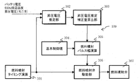
- FIG. 3 is an example of a control block diagram for correcting the fuel injection pulse width based on the estimated boosted voltage with respect to the drive control value of the fuel injection valve according to the embodiment of the present invention.
- the ECU (109) functions as blocks 301 to 306.
- Block 301 is a block for calculating the fuel injection timing.
- Block 301 sets the injection timing for each cylinder in accordance with conditions such as engine speed, engine water temperature, and injection stroke information (information indicating one of the steps of intake, compression, combustion, and exhaust of one combustion cycle). calculate.
- Block 302 is a block of the boost voltage estimation unit.
- Booster monitored by booster circuit driver (210) from fuel injection timing for each cylinder, ambient temperature of ECUE (109), substrate temperature of ECU (109), booster temperature, battery voltage, or battery voltage smoothing value
- the boost voltage is estimated from the voltage as a starting point, and the boost voltage estimate is calculated. A method for calculating the boosted voltage estimated value will be described later.
- the block 303 calculates a correction amount based on the boosted voltage estimated value so as to suppress fuel variation due to the boosted voltage drop.
- Block 304 calculates a basic control value (basic fuel injection pulse) according to conditions such as engine speed, load, and engine water temperature.
- Block 305 calculates the injection pulse width by reflecting the fuel correction amount based on the boosted voltage estimated value with respect to the basic control value.
- block 305 calculates a pulse width for injecting multiple times according to the number of multi-stage injections and the division ratio.
- Block 306 is a fuel injection valve drive unit. According to the fuel injection timing and the fuel injection pulse width, the fuel injection is executed by outputting a drive current to the fuel injection valve of the block 307.
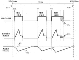
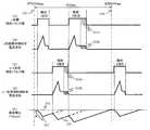
- FIG. 4 is a chart showing an example of the required operation during multistage injection.
- the chart shows the injection pulse width, the current waveform of the fuel injection valve, and the boosted voltage (Vboost) in order from the top.
- Vboost boosted voltage
- the required operation will be described by taking as an example the case of performing multistage injection three times in the same cylinder during a predetermined period (407 to 408) in one cycle (one combustion cycle).
- Vboost the boosted voltage
- the reference voltage (401) is a voltage when the booster circuit (211) is fully charged.
- the voltage drops by a predetermined amount per injection at the timing of the first injection (403), the second injection (404), and the third injection (405).
- the voltage is boosted toward the reference voltage (401). If the boosted voltage has returned to the reference voltage (401) as in the second injection (404), a stable fuel injection amount can be injected.
- a predetermined period (407 408) In the case of multiple fuel injections, the voltage drop of all boosted voltages and the boosted voltage at the time of injection before the first fuel injection valve drive (BTDC 10deg of 407 in FIG. 4) Is estimated.
- the shaded portion indicated by 406b is also extended in the current waveform of the fuel injection valve.
- the details of the method for estimating the boosted voltage will be described later, but this embodiment can satisfy the request for the desired injection timing when a short-term injection that does not meet the charge of the boosted voltage is required.
- An object is to suppress variations in fuel injection amount due to injection of boosted voltage during charging.
- the microcomputer (204) functions as a correction unit that corrects the fuel injection pulse width to be increased when the estimated boosted voltage is smaller than the reference voltage. Thereby, a decrease in the fuel injection amount can be suppressed.
- FIG. 5 is a chart showing an example different from that shown in FIG. 4 as the required operation during multi-stage injection.
- the chart is, in order from the top, (A) n cylinder injection pulse width, (B) n cylinder fuel injection current waveform, (C) n + 1 cylinder injection pulse width, (D) n + 1 cylinder fuel injection current waveform, (E) boosting It represents the voltage (Vboost).
- This figure shows the combination of different cylinders (A) and (C), and multi-stage injection of 3 times within the stroke of 180 deg crank angle during the predetermined period (505 to 506) in one cycle and once in the next stroke. Indicates the case to be performed.
- the fuel injection amount When the boosted voltage at the time of fuel injection is lower than the reference voltage (501), the fuel injection amount will decrease, so the fuel with the injection pulse width at the hatched portion indicated by the second injection 503a and the third injection 504a
- the increase correction is performed according to the boosted voltage estimated value. With the correction of the injection pulse width, the hatched portions indicated by 503b of the current waveform (D) and 504b of the current waveform (B) of the fuel injection valve are extended.
- the boosted voltage has returned to the reference voltage (501), so correction for the injection pulse width of the fourth injection is not performed.
- the calculation of the boosted voltage drop amount (507) and the drop time per one fuel injection valve will be described with reference to FIG.
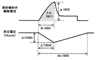
- FIG. 6 is a chart showing the relationship between the drive current of the fuel injection valve, the boosted voltage, and the return reference time.
- the charge ⁇ Q (601) consumed when one fuel injection valve is driven is represented by a substantially triangular area shown in FIG. ⁇ Q is calculated by the following equation (1) from dt (602) and ip (603).
- dt (602) is the time from when the drive current of the fuel injection valve flows until it reaches the peak current, and is equivalent to the drop time ⁇ T (604) of the boosted voltage (Vboost).
- the dt (602) is set by any two or more of the battery voltage, the battery voltage smoothed value, the ambient temperature of the ECU, the substrate temperature of the ECU, or the temperature of the booster circuit.
- the battery voltage smoothing value is obtained by suppressing the fluctuation of the battery voltage by applying a weighted average filter to the battery voltage.
- Ip (603) is the peak current of the fuel injection valve, and is preset according to the fuel pressure used. Note that ip (603) is the maximum value of the drive current supplied to the fuel injection device.
- the boost voltage drop amount ⁇ V (605) per one fuel injection valve drive can be calculated by the following formula (2).
- ⁇ V is called boost voltage drop
- ⁇ V ⁇ Q / C (2)
- ⁇ V represents the amount of decrease in the boost voltage when the fuel injection device performs one fuel injection with the booster circuit (211) fully charged.
- the electrostatic capacity: C is determined according to the capacitor used in the booster circuit (211). However, since the capacitor includes variations due to temperature, it is preferable to correct the electrostatic capacity with a temperature sensor. From the charge calculation formula, when two fuel injection valves are driven simultaneously, the consumed charge ⁇ Q (601) is doubled, and the boost voltage drop amount ⁇ V (605) is also doubled. Further, dtc (606) is a return reference time, and the current (ic) charged in the booster circuit can be calculated by the following equation (3).
- ⁇ V ic ⁇ dtc / C (4) If the charged current (ic) and the capacitance (C) are fixed values, the recovery reference time: dtc (606) also doubles when the boost voltage drop amount ⁇ V (605) doubles. .
- dtc indicates that the booster circuit (211) is completely discharged after the booster voltage starts to drop when the fuel injection device performs one fuel injection with the booster circuit (211) fully charged. Indicates the time until charging.
- the boosted voltage in the booster circuit drive unit (210) described above is A / D (analog signal to digital signal conversion) before a predetermined period (407 in FIG. 4 and 505 in FIG. 5) in this embodiment. ) And take in every cylinder.
- the monitored value of the boosted voltage is hereinafter referred to as a boosted voltage AD value.
- the boosted voltage estimated value V ⁇ is calculated by the following equation (5).
- V ⁇ (Vad + C1) - ⁇ V ⁇ N + ⁇ V ⁇ (Tsum-dt) / (dtc-dt) (5)
- Vad is an AD value of the boosted voltage at a timing corresponding to a predetermined crank angle (for example, BTDC 10 deg).
- C1 is a correction amount at the time of first descent described later.
- ⁇ V is a value calculated from the equations (1) and (2).
- dtc (606) is the above-described return reference time.
- Tsum is the boost voltage recovery time and is calculated by the following equation (6).
- T k is the timing of the kth fuel injection after storing the AD value of the boosted voltage.
- the microcomputer (204) functions as an estimation unit that estimates boosted voltages at all fuel injection timings in one combustion cycle before the first fuel injection in one combustion cycle.
- the microcomputer (204) includes the boost voltage drop amount ⁇ V, the time dt (602) until the peak current ip (603) is reached, the return reference time dtc (606), and the fuel in one combustion cycle. Based on the number of injections N, the boosted voltage at the fuel injection timing is estimated. Thereby, the boosted voltage can be estimated easily.
- the maximum value of the estimated boosted voltage V ⁇ has a reference voltage as an upper limit.
- the reference voltage in the present embodiment is a boosted voltage monitored after the initial power-on of the vehicle power supply (battery) and before fuel injection, and is stored in the microcomputer (204). That is, the reference voltage is a voltage of the booster circuit (211) measured after turning the ignition switch from OFF to before the fuel injection device injects fuel. Thereby, the accuracy of the reference voltage can be ensured.
- the calculation formula for the boosted voltage recovery time Tsum assumes a case where the maximum number of multistage injections is five, but the calculation formula (6) may be changed according to the maximum number of multistage injections.
- the return reference time dtc (606) is set to the actual value of the boost voltage return reference time.
- the boost voltage restoration reference time will be described with reference to FIG.
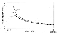
- FIG. 7 is a chart showing the relationship between the battery voltage and the return reference time of the boosted voltage.
- Reference numeral 701 denotes a case where the ECU board temperature is high, and reference numeral 702 denotes a case where the ECU board temperature is low.
- the ECU substrate temperature is used here, any one or more of the ambient temperature of the ECU and the temperature of the booster circuit may be used.
- the battery voltage is used here, it may be a battery voltage smoothed value. Thereby, the influence of the fluctuation
- the microcomputer (204) sets the return reference time dtc (606) according to the battery voltage and the temperature of the ECU (109) (the ambient temperature of the ECU, the substrate temperature of the ECU, or the temperature of the booster circuit). For example, the microcomputer (204) stores in advance a return reference time dtc (606) corresponding to the battery voltage and the temperature of the ECU (109). Thereby, the accuracy of estimating the boosted voltage is improved.
- the microcomputer (204) sets the return reference time so that the return reference time dtc (606) increases as the battery voltage decreases, and the return reference time dtc increases as the ECU temperature increases.
- the return reference time is set so that (606) becomes larger.
- the initial drop correction amount C1 is calculated by the following formula (7).
- T 0 the time from TDC to the first injection.
- the reflection of the correction amount C1 at the time of first drop to the estimated boosted voltage V ⁇ will be described.
- the boosted voltage AD value is compared with a reference voltage.
- the boost voltage AD value is close to the reference voltage (boost voltage AD value ⁇ reference voltage)
- the boost voltage AD value is higher than the reference voltage.
- Is low boosted voltage AD value ⁇ reference voltage
- the initial drop correction amount C1 obtained from the calculation formula (7) is reflected in the boosted voltage estimated value V ⁇ .
- the estimated value of the boosted voltage can be obtained by each means (each unit) described so far.
- the injection pulse width and boost voltage estimation correction calculation means (calculation unit) will be described. Note that the boost voltage estimation correction is calculated individually for all the fuel injection counts within the predetermined period at a timing before the predetermined period.
- the cylinder-specific injection pulse width is calculated by the following equation (8).
- the boost voltage estimation correction is a correction amount that distributes the boost voltage estimation correction amount (for the maximum number of injections of multistage injection) within one stroke (180 deg) based on the information of the injection cylinder (injection timing of each cylinder) and the number of injections. It becomes. Since the amount of decrease in the fuel injection amount increases as the amount of decrease in the boost voltage due to injection of the boost voltage during charging increases, the fuel injection amount is set to be suppressed. A specific setting example is shown in FIG.
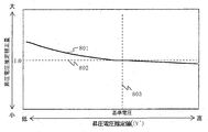
- FIG. 8 is a chart showing the relationship between the boosted voltage estimated value and the boosted voltage estimated correction amount according to the embodiment of the present invention.
- a solid line 801 represents a boost voltage estimation correction amount. The lower the boost voltage, the larger the correction amount and the longer the fuel injection pulse width.
- the correction amount is set to reduce the fuel injection pulse width by reducing the correction amount.
- the microcomputer (204) functions as a correction unit that corrects the fuel injection pulse width to be smaller when the boosted voltage is larger than the reference voltage. Thereby, it can suppress that fuel injection quantity increases.
- the dotted line 802 indicates that when the boosted voltage is charged near the reference voltage (803), the boosted voltage estimation correction amount is invalid and the injection pulse width is not extended or reduced.
- the injection pulse width is corrected by multiplying the boosted voltage estimation correction, and therefore becomes substantially invalid at 1.0.
- the microcomputer (204) functions as a correction unit that corrects the fuel injection amount at each fuel injection timing in accordance with the estimated boosted voltage.
- the microcomputer (204) estimates boosted voltages at all fuel injection timings in one combustion cycle for all cylinders before the first fuel injection in one combustion cycle of a certain cylinder. Thereby, the boost voltage can be estimated in consideration of not only multi-stage injection of one cylinder but also multi-stage injection of other cylinders.
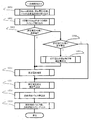
- FIG. 9 is a flowchart of fuel injection control according to the embodiment of the present invention.
- the microcomputer (204) performs an operation by interruption every predetermined crank angle (for example, BTDC 10 deg) according to this flow.
- step S901 the microcomputer (204) takes in the input parameters such as the above-described reference voltage, boost voltage AD value, ECU substrate temperature, ECU ambient temperature, boost circuit temperature, battery voltage, and battery voltage annealing value.
- step S902 the microcomputer (204) takes in the injection timings for all the fuel injection times in one stroke (180 deg).
- step S903 the microcomputer (204) determines whether or not it is necessary to calculate a correction amount at the first drop of the boost voltage.
- the microcomputer (204) determines whether or not the boosted voltage AD value is equal to the reference voltage. For example, when the difference between the boost voltage AD value and the reference voltage is equal to or smaller than a predetermined threshold, the microcomputer (204) determines that the boost voltage AD value is equal to the reference voltage.
- step S906 If the condition of boosted voltage AD value ⁇ reference voltage is satisfied, the microcomputer (204) proceeds to step S906. When the condition in step S903 is not satisfied, the microcomputer (204) proceeds to step S904. When the condition of boosted voltage AD value ⁇ reference voltage is satisfied (S904; YES), the microcomputer (204) calculates the correction amount C1 at the first drop of the boosted voltage value in step S905. On the other hand, when the condition of step S904 is not satisfied (boosted voltage AD value> reference voltage), the microcomputer (204) proceeds to step S907.
- step S906 the microcomputer (204) calculates the boosted voltage estimated value V ⁇ from the boosted voltage AD value, the injection timing, and the initial drop correction amount C1.
- the return reference of the boosted voltage is determined by any two or more of the ECU substrate temperature, the ECU ambient temperature, the booster circuit temperature, the battery voltage, or the battery voltage smoothed value.
- Time dtc (606) is set.
- step S907 the microcomputer (204) calculates a boost voltage estimation correction amount as shown in FIG. 8 from the boost voltage estimated value V ⁇ or the boost voltage AD value.
- the boosted voltage estimated value V ⁇ has the reference voltage as the upper limit value, if the condition of step S904 is not satisfied (boosted voltage AD value> reference voltage) and the process proceeds to step S907, the ECU (109)
- the boosted voltage estimation correction amount is calculated by replacing the horizontal axis of 8 with the boosted voltage AD value from the boosted voltage estimated value.
- step S908 the microcomputer (204) calculates the fuel injection pulse width by reflecting the boost voltage estimation correction amount in the basic control value.
- step S909 the calculated fuel injection pulse width and fuel injection timing are set in the injection driver, and the injection driver outputs a drive current to control the fuel injection valve.
- the boosted voltage is injected during charging without shifting the required injection timing. It is possible to suppress variations in the fuel injection amount due to the operation.
- the present invention is not limited to the above-described embodiment, and includes various modifications.
- the above-described embodiment has been described in detail for easy understanding of the present invention, and is not necessarily limited to one having all the configurations described.
- a part of the configuration of an embodiment can be replaced with the configuration of another embodiment, and the configuration of another embodiment can be added to the configuration of an embodiment.
- the microcomputer (204) is based on the amount of power supplied to the booster circuit (211), the amount of power consumed when the fuel injection device performs one fuel injection, and the number of fuel injections in one combustion cycle.
- the boosted voltage at the fuel injection timing may be estimated.
- the boosted voltage can be estimated from the electric energy.
- the microcomputer (204) also determines the boosted voltage at a predetermined timing before the first fuel injection in one combustion cycle, the rate of change of the boosted voltage when the fuel injector is injected once, and the fuel injector
- the boosted voltage at the fuel injection timing may be estimated based on the rate of change of the boosted voltage when the booster circuit (211) is charged after one fuel injection and the number of times of fuel injection during one combustion cycle. .
- the boost voltage can be estimated from the rate of change (slope) of the boost voltage.
- each of the above-described configurations, functions, processing units, processing means, and the like may be realized by hardware by designing a part or all of them with, for example, an integrated circuit.
- Each of the above-described configurations, functions, and the like may be realized by software by interpreting and executing a program that realizes each function by the processor.
- Information such as programs, tables, and files for realizing each function can be stored in a recording device such as a memory, a hard disk, or an SSD (Solid State Drive), or a recording medium such as an IC card, an SD card, or a DVD.
Landscapes
- Engineering & Computer Science (AREA)
- Chemical & Material Sciences (AREA)
- Combustion & Propulsion (AREA)
- Mechanical Engineering (AREA)
- General Engineering & Computer Science (AREA)
- Electrical Control Of Air Or Fuel Supplied To Internal-Combustion Engine (AREA)
- Fuel-Injection Apparatus (AREA)
- Combined Controls Of Internal Combustion Engines (AREA)
Abstract
Description
dt(602)は燃料噴射弁の駆動電流が流れてからピーク電流に到達するまでの時間であり、昇圧電圧(Vboost)の降下時間ΔT(604)と等価である。dt(602)は、バッテリ電圧、またはバッテリ電圧なまし値、またはECUの周辺温度、またはECUの基板温度、または昇圧回路の温度、のいずれか2つ以上によって設定しておく。ここで、バッテリ電圧なまし値とは、バッテリ電圧に対して加重平均フィルタを掛けることにより、バッテリ電圧の変動を抑えたものとする。
ΔV=ΔQ/C (2)
ここで、ΔVは、昇圧回路(211)が完全に充電された状態で燃料噴射装置が1回燃料噴射したときの昇圧電圧の降下量を示す。
電荷算出式より、上式(3)を下式(4)に変換できる。
チャージされる電流(ic)と、静電容量(C)を仮に固定値とした場合、昇圧電圧降下量ΔV(605)が2倍になると、復帰基準時間:dtc(606)も2倍となる。
ここで、Vadは所定のクランク角(例えば、BTDC10deg)に対応するタイミングにおける昇圧電圧のAD値である。C1は、後述する初回降下時補正量である。ΔVは式(1)及び(2)から算出される値である。dtc(606)は、前述した復帰基準時間である。Tsumは、昇圧電圧復帰時間であり、下式(6)により算出する。
ここで、Tkは、昇圧電圧のAD値を記憶した後のk回目の燃料噴射のタイミングである。
ここで、T0は、TDCから初回噴射までの時間である。
昇圧電圧推定補正は、1行程(180deg)内の昇圧電圧推定補正量(多段噴射の最大噴射回数分)を噴射気筒(各気筒の噴射タイミング)と噴射回数の情報をもとに分配した補正量となる。昇圧電圧がチャージ中に噴射することによる昇圧電圧の降下量が大きくなるのに伴い、燃料噴射量の低下量も大きくなることから、燃料噴射量の低下を抑えるように設定する。具体的な設定例を図8に示す。
106…燃料噴射弁
109…ECU(エンジンコントロールユニット)
201…バッテリ
207…燃料噴射制御回路
211…昇圧回路
212a…昇圧電圧ドライバ
212b…バッテリ電圧ドライバ
214…コイル負荷
Claims (12)
- バッテリから供給される第1の電圧を昇圧し、昇圧された第2の電圧を燃料噴射装置へ供給する昇圧回路と、
前記昇圧回路から前記燃料噴射装置に供給される前記第2の電圧をオン/オフするスイッチと、
前記スイッチを制御する演算装置と、を備え、
前記演算装置は、
1燃焼サイクル中の最初の燃料噴射の前に、前記1燃焼サイクル中のすべての燃料噴射タイミングにおける前記第2の電圧を推定する推定部と、
推定された前記第2の電圧に応じてそれぞれの燃料噴射タイミングにおける燃料噴射量を補正する補正部と、
を備えることを特徴とする内燃機関の制御装置。 - 請求項1に記載の内燃機関の制御装置であって、
前記推定部は、
ある気筒の1燃焼サイクル中の最初の燃料噴射の前に、すべての気筒について前記1燃焼サイクル中のすべての燃料噴射タイミングにおける前記第2の電圧を推定する
ことを特徴とする内燃機関の制御装置。 - 請求項1に記載の内燃機関の制御装置であって、
前記推定部は、
昇圧回路に供給される電力量と、前記燃料噴射装置が1回燃料噴射したときに消費される電力量と、前記1燃焼サイクル中の燃料噴射回数とに基づいて、燃料噴射タイミングにおける前記第2の電圧を推定する
ことを特徴とする内燃機関の制御装置。 - 請求項1に記載の内燃機関の制御装置であって、
前記推定部は、
前記1燃焼サイクル中の最初の燃料噴射の前の所定のタイミングにおける前記第2の電圧と、前記燃料噴射装置が1回燃料噴射したときの前記第2の電圧の変化率と、前記燃料噴射装置が1回燃料噴射した後、前記昇圧回路が充電されるときの前記第2の電圧の変化率と、前記1燃焼サイクル中の燃料噴射回数とに基づいて、燃料噴射タイミングにおける前記第2の電圧を推定する
ことを特徴とする内燃機関の制御装置。 - 請求項1に記載の内燃機関の制御装置であって、
前記推定部は、
前記昇圧回路が完全に充電された状態で前記燃料噴射装置が1回燃料噴射したときの前記第2の電圧の降下量を示す昇圧電圧降下量と、前記燃料噴射装置に駆動電流が供給されてから駆動電流の最大値であるピーク電流に達するまでの時間と、前記昇圧回路が完全に充電された状態で前記燃料噴射装置が1回燃料噴射したときに前記第2の電圧が降下を開始してから前記昇圧回路が完全に充電されるまでの時間を示す復帰基準時間と、前記1燃焼サイクル中の燃料噴射回数とに基づいて、燃料噴射タイミングにおける前記第2の電圧を推定する
ことを特徴とする内燃機関の制御装置。 - 請求項1に記載の内燃機関の制御装置であって、
前記推定部は、
前記第1の電圧及び前記制御装置の温度に応じた前記復帰基準時間を設定する
ことを特徴とする内燃機関の制御装置。 - 請求項6に記載の内燃機関の制御装置であって、
前記制御装置の温度は、
前記制御装置の基板温度又は前記昇圧回路の温度である
ことを特徴とする内燃機関の制御装置。 - 請求項6に記載の内燃機関の制御装置であって、
前記推定部は、
前記第1の電圧のなまし値に応じて、前記復帰基準時間を設定する
ことを特徴とする内燃機関の制御装置。 - 請求項6に記載の内燃機関の制御装置であって、
前記推定部は、
前記第1の電圧が小さくなるにつれて、前記復帰基準時間が大きくなるように前記復帰基準時間を設定し、かつ、
前記制御装置の温度が大きくなるにつれて、前記復帰基準時間が大きくなるように前記復帰基準時間を設定する
ことを特徴とする内燃機関の制御装置。 - 請求項1に記載の内燃機関の制御装置であって、
前記補正部は、
推定された前記第2の電圧が、前記昇圧回路が完全に充電されたときの電圧を示す基準電圧より小さい場合、燃料噴射パルス幅を大きくするように補正する
ことを特徴とする内燃機関の制御装置。 - 請求項10に記載の内燃機関の制御装置であって、
前記基準電圧は、
イグニッションスイッチをオフからオンにした後、燃料噴射装置が燃料噴射する前に測定された前記昇圧回路の電圧である
ことを特徴とする内燃機関の制御装置。 - 請求項1に記載の内燃機関の制御装置であって、
前記補正部は、
前記第2の電圧が、前記昇圧回路が完全に充電されたときの電圧を示す基準電圧より大きい場合、燃料噴射パルス幅を小さくするように補正する
ことを特徴とする内燃機関の制御装置。
Priority Applications (3)
| Application Number | Priority Date | Filing Date | Title |
|---|---|---|---|
| US15/547,973 US10450995B2 (en) | 2015-02-05 | 2016-01-29 | Control device for internal combustion engine |
| CN201680004285.3A CN107110048B (zh) | 2015-02-05 | 2016-01-29 | 内燃机的控制装置 |
| JP2016573320A JP6393346B2 (ja) | 2015-02-05 | 2016-01-29 | 内燃機関の制御装置 |
Applications Claiming Priority (2)
| Application Number | Priority Date | Filing Date | Title |
|---|---|---|---|
| JP2015020821 | 2015-02-05 | ||
| JP2015-020821 | 2015-02-05 |
Publications (1)
| Publication Number | Publication Date |
|---|---|
| WO2016125688A1 true WO2016125688A1 (ja) | 2016-08-11 |
Family
ID=56564035
Family Applications (1)
| Application Number | Title | Priority Date | Filing Date |
|---|---|---|---|
| PCT/JP2016/052565 Ceased WO2016125688A1 (ja) | 2015-02-05 | 2016-01-29 | 内燃機関の制御装置 |
Country Status (4)
| Country | Link |
|---|---|
| US (1) | US10450995B2 (ja) |
| JP (1) | JP6393346B2 (ja) |
| CN (1) | CN107110048B (ja) |
| WO (1) | WO2016125688A1 (ja) |
Cited By (5)
| Publication number | Priority date | Publication date | Assignee | Title |
|---|---|---|---|---|
| WO2019122593A1 (fr) * | 2017-12-21 | 2019-06-27 | Continental Automotive France | Procédé de régulation de la tension de sortie d'un convertisseur de tension continu-continu d'un calculateur de contrôle d'un moteur de véhicule automobile |
| US20210404403A1 (en) * | 2020-06-29 | 2021-12-30 | Denso Corporation | Injection control device |
| JP2024022187A (ja) * | 2022-08-05 | 2024-02-16 | 株式会社デンソー | 噴射制御装置 |
| JP7630576B1 (ja) | 2023-09-11 | 2025-02-17 | 本田技研工業株式会社 | 噴射制御装置 |
| US20250146451A1 (en) * | 2022-02-07 | 2025-05-08 | Hitachi Astemo, Ltd. | Electronic control device and method for controlling electronic control device |
Families Citing this family (7)
| Publication number | Priority date | Publication date | Assignee | Title |
|---|---|---|---|---|
| JP6372426B2 (ja) * | 2015-06-12 | 2018-08-15 | 株式会社デンソー | 噴射弁駆動装置 |
| JP6972844B2 (ja) * | 2017-09-27 | 2021-11-24 | 株式会社デンソー | インジェクタ駆動装置 |
| US10443533B2 (en) * | 2017-10-23 | 2019-10-15 | GM Global Technology Operations LLC | Mild hybrid powertrain with simplified fuel injector boost |
| JP7006204B2 (ja) * | 2017-12-05 | 2022-01-24 | 株式会社デンソー | 噴射制御装置 |
| JP7172753B2 (ja) * | 2019-03-07 | 2022-11-16 | 株式会社デンソー | 噴射制御装置 |
| TWI704378B (zh) * | 2019-11-21 | 2020-09-11 | 宏碁股份有限公司 | 頭戴式顯示裝置 |
| DE102022211461A1 (de) * | 2022-10-28 | 2024-05-08 | Robert Bosch Gesellschaft mit beschränkter Haftung | Verfahren zur Prädiktion einer Ausgangsspannung an einem Gleichspannungswandler, Kraftstoffeinspritzsystem, Recheneinheit und Computerprogramm |
Citations (3)
| Publication number | Priority date | Publication date | Assignee | Title |
|---|---|---|---|---|
| JPH09317540A (ja) * | 1996-05-23 | 1997-12-09 | Toyota Motor Corp | 内燃機関の燃料噴射制御装置 |
| JP2000054932A (ja) * | 1998-07-28 | 2000-02-22 | Robert Bosch Gmbh | 少なくとも1つの磁石弁の制御方法及び装置 |
| JP2014202147A (ja) * | 2013-04-05 | 2014-10-27 | 本田技研工業株式会社 | 電磁弁駆動装置 |
Family Cites Families (13)
| Publication number | Priority date | Publication date | Assignee | Title |
|---|---|---|---|---|
| US3549132A (en) * | 1967-10-09 | 1970-12-22 | Elmer A Haase | Combustion engine fuel control |
| DE19723932C1 (de) * | 1997-06-06 | 1998-12-24 | Siemens Ag | Verfahren zum Ansteuern wenigstens eines kapazitiven Stellgliedes |
| JP2001317394A (ja) * | 2000-04-28 | 2001-11-16 | Mitsubishi Electric Corp | 筒内噴射エンジンの燃料噴射制御装置 |
| JP4474423B2 (ja) * | 2007-01-12 | 2010-06-02 | 日立オートモティブシステムズ株式会社 | 内燃機関制御装置 |
| JP4776651B2 (ja) * | 2008-03-28 | 2011-09-21 | 日立オートモティブシステムズ株式会社 | 内燃機関制御装置 |
| JP5198496B2 (ja) * | 2010-03-09 | 2013-05-15 | 日立オートモティブシステムズ株式会社 | 内燃機関のエンジンコントロールユニット |
| JP5260597B2 (ja) * | 2010-05-27 | 2013-08-14 | 日立オートモティブシステムズ株式会社 | 内燃機関の燃料噴射装置及び制御方法 |
| CN202250430U (zh) * | 2011-08-31 | 2012-05-30 | 日立汽车部件(苏州)有限公司 | 电磁负载控制装置 |
| JP5838074B2 (ja) * | 2011-11-08 | 2015-12-24 | 日立オートモティブシステムズ株式会社 | 内燃機関の燃料噴射制御装置 |
| CN104093959A (zh) * | 2012-02-01 | 2014-10-08 | 丰田自动车株式会社 | 内燃机的控制装置 |
| JP5462387B1 (ja) * | 2013-04-18 | 2014-04-02 | 三菱電機株式会社 | 車載エンジン制御装置及びその制御方法 |
| JP5619253B1 (ja) * | 2013-10-15 | 2014-11-05 | 三菱電機株式会社 | 誘導性負荷の給電制御装置 |
| JP6181865B2 (ja) * | 2014-05-13 | 2017-08-16 | 日立オートモティブシステムズ株式会社 | 電子制御装置 |
-
2016
- 2016-01-29 WO PCT/JP2016/052565 patent/WO2016125688A1/ja not_active Ceased
- 2016-01-29 JP JP2016573320A patent/JP6393346B2/ja not_active Expired - Fee Related
- 2016-01-29 US US15/547,973 patent/US10450995B2/en active Active
- 2016-01-29 CN CN201680004285.3A patent/CN107110048B/zh not_active Expired - Fee Related
Patent Citations (3)
| Publication number | Priority date | Publication date | Assignee | Title |
|---|---|---|---|---|
| JPH09317540A (ja) * | 1996-05-23 | 1997-12-09 | Toyota Motor Corp | 内燃機関の燃料噴射制御装置 |
| JP2000054932A (ja) * | 1998-07-28 | 2000-02-22 | Robert Bosch Gmbh | 少なくとも1つの磁石弁の制御方法及び装置 |
| JP2014202147A (ja) * | 2013-04-05 | 2014-10-27 | 本田技研工業株式会社 | 電磁弁駆動装置 |
Cited By (11)
| Publication number | Priority date | Publication date | Assignee | Title |
|---|---|---|---|---|
| WO2019122593A1 (fr) * | 2017-12-21 | 2019-06-27 | Continental Automotive France | Procédé de régulation de la tension de sortie d'un convertisseur de tension continu-continu d'un calculateur de contrôle d'un moteur de véhicule automobile |
| FR3075882A1 (fr) * | 2017-12-21 | 2019-06-28 | Continental Automotive France | Procede de regulation de la tension de sortie d'un convertisseur de tension continu-continu d'un calculateur de controle d'un moteur de vehicule automobile |
| US11408364B2 (en) | 2017-12-21 | 2022-08-09 | Continental Automotive France | Method for regulating the output voltage of a DC/DC voltage converter of a control computer of a motor vehicle engine |
| US20210404403A1 (en) * | 2020-06-29 | 2021-12-30 | Denso Corporation | Injection control device |
| US11525418B2 (en) * | 2020-06-29 | 2022-12-13 | Denso Corporation | Injection control device |
| US20250146451A1 (en) * | 2022-02-07 | 2025-05-08 | Hitachi Astemo, Ltd. | Electronic control device and method for controlling electronic control device |
| US12429009B2 (en) * | 2022-02-07 | 2025-09-30 | Hitachi Astemo, Ltd. | Electronic control device and method for controlling electronic control device |
| JP2024022187A (ja) * | 2022-08-05 | 2024-02-16 | 株式会社デンソー | 噴射制御装置 |
| JP7779214B2 (ja) | 2022-08-05 | 2025-12-03 | 株式会社デンソー | 噴射制御装置 |
| JP7630576B1 (ja) | 2023-09-11 | 2025-02-17 | 本田技研工業株式会社 | 噴射制御装置 |
| JP2025040164A (ja) * | 2023-09-11 | 2025-03-24 | 本田技研工業株式会社 | 噴射制御装置 |
Also Published As
| Publication number | Publication date |
|---|---|
| CN107110048B (zh) | 2020-10-27 |
| JPWO2016125688A1 (ja) | 2017-10-19 |
| US10450995B2 (en) | 2019-10-22 |
| JP6393346B2 (ja) | 2018-09-19 |
| CN107110048A (zh) | 2017-08-29 |
| US20180023503A1 (en) | 2018-01-25 |
Similar Documents
| Publication | Publication Date | Title |
|---|---|---|
| JP6393346B2 (ja) | 内燃機関の制御装置 | |
| JP6314733B2 (ja) | 内燃機関の燃料噴射制御装置 | |
| US9835105B2 (en) | Fuel injection control device for internal combustion engine | |
| JP6477321B2 (ja) | 内燃機関の燃料噴射制御装置 | |
| JP6114697B2 (ja) | 内燃機関を制御する方法 | |
| JP2010255444A (ja) | 内燃機関の燃料噴射制御装置及び方法 | |
| JP6121552B2 (ja) | 内燃機関の燃料噴射制御装置 | |
| CN102192030A (zh) | 内燃机的燃料喷射装置以及燃料喷射控制方法 | |
| JP6508228B2 (ja) | 内燃機関の燃料噴射制御装置 | |
| US11060474B2 (en) | Fuel injection control device | |
| CN101617113A (zh) | 用于调节内燃机喷射器的喷射量的方法 | |
| JP2016153615A (ja) | 燃料噴射弁駆動装置 | |
| JP7006155B2 (ja) | 燃料噴射制御装置 | |
| JP6493334B2 (ja) | 内燃機関の燃料噴射制御装置 | |
| JP6431826B2 (ja) | 内燃機関の燃料噴射制御装置 | |
| JP2013137028A (ja) | 内燃機関の燃料噴射制御装置及び方法 | |
| JP7035466B2 (ja) | 燃料噴射制御装置 | |
| JP5633479B2 (ja) | 内燃機関の制御装置 | |
| JP2019027299A (ja) | 燃料噴射制御装置 | |
| JP2020041504A (ja) | 内燃機関の制御装置 | |
| JP2017133438A (ja) | 内燃機関の燃料噴射制御装置及び燃料噴射システム | |
| CN102177331A (zh) | 用于控制燃料喷射器的方法和控制装置 | |
| JP2007187106A (ja) | 内燃機関の点火制御装置 | |
| JP2011099334A (ja) | 内燃機関の燃焼制御装置 | |
| WO2018096940A1 (ja) | 燃料噴射制御装置 |
Legal Events
| Date | Code | Title | Description |
|---|---|---|---|
| 121 | Ep: the epo has been informed by wipo that ep was designated in this application |
Ref document number: 16746519 Country of ref document: EP Kind code of ref document: A1 |
|
| ENP | Entry into the national phase |
Ref document number: 2016573320 Country of ref document: JP Kind code of ref document: A |
|
| WWE | Wipo information: entry into national phase |
Ref document number: 15547973 Country of ref document: US |
|
| NENP | Non-entry into the national phase |
Ref country code: DE |
|
| 122 | Ep: pct application non-entry in european phase |
Ref document number: 16746519 Country of ref document: EP Kind code of ref document: A1 |